WO2023276181A1 - 電力変換装置 - Google Patents
電力変換装置 Download PDFInfo
- Publication number
- WO2023276181A1 WO2023276181A1 PCT/JP2021/041409 JP2021041409W WO2023276181A1 WO 2023276181 A1 WO2023276181 A1 WO 2023276181A1 JP 2021041409 W JP2021041409 W JP 2021041409W WO 2023276181 A1 WO2023276181 A1 WO 2023276181A1
- Authority
- WO
- WIPO (PCT)
- Prior art keywords
- axis
- magnetic flux
- gain
- value
- power converter
- Prior art date
- Legal status (The legal status is an assumption and is not a legal conclusion. Google has not performed a legal analysis and makes no representation as to the accuracy of the status listed.)
- Ceased
Links
Images





Classifications
-
- H—ELECTRICITY
- H02—GENERATION; CONVERSION OR DISTRIBUTION OF ELECTRIC POWER
- H02P—CONTROL OR REGULATION OF ELECTRIC MOTORS, ELECTRIC GENERATORS OR DYNAMO-ELECTRIC CONVERTERS; CONTROLLING TRANSFORMERS, REACTORS OR CHOKE COILS
- H02P21/00—Arrangements or methods for the control of electric machines by vector control, e.g. by control of field orientation
- H02P21/24—Vector control not involving the use of rotor position or rotor speed sensors
- H02P21/26—Rotor flux based control
-
- H—ELECTRICITY
- H02—GENERATION; CONVERSION OR DISTRIBUTION OF ELECTRIC POWER
- H02P—CONTROL OR REGULATION OF ELECTRIC MOTORS, ELECTRIC GENERATORS OR DYNAMO-ELECTRIC CONVERTERS; CONTROLLING TRANSFORMERS, REACTORS OR CHOKE COILS
- H02P21/00—Arrangements or methods for the control of electric machines by vector control, e.g. by control of field orientation
- H02P21/0003—Control strategies in general, e.g. linear type, e.g. P, PI, PID, using robust control
- H02P21/0014—Control strategies in general, e.g. linear type, e.g. P, PI, PID, using robust control using neural networks
-
- H—ELECTRICITY
- H02—GENERATION; CONVERSION OR DISTRIBUTION OF ELECTRIC POWER
- H02P—CONTROL OR REGULATION OF ELECTRIC MOTORS, ELECTRIC GENERATORS OR DYNAMO-ELECTRIC CONVERTERS; CONTROLLING TRANSFORMERS, REACTORS OR CHOKE COILS
- H02P21/00—Arrangements or methods for the control of electric machines by vector control, e.g. by control of field orientation
- H02P21/05—Arrangements or methods for the control of electric machines by vector control, e.g. by control of field orientation specially adapted for damping motor oscillations, e.g. for reducing hunting
-
- H—ELECTRICITY
- H02—GENERATION; CONVERSION OR DISTRIBUTION OF ELECTRIC POWER
- H02P—CONTROL OR REGULATION OF ELECTRIC MOTORS, ELECTRIC GENERATORS OR DYNAMO-ELECTRIC CONVERTERS; CONTROLLING TRANSFORMERS, REACTORS OR CHOKE COILS
- H02P21/00—Arrangements or methods for the control of electric machines by vector control, e.g. by control of field orientation
- H02P21/14—Estimation or adaptation of machine parameters, e.g. flux, current or voltage
- H02P21/141—Flux estimation
-
- H—ELECTRICITY
- H02—GENERATION; CONVERSION OR DISTRIBUTION OF ELECTRIC POWER
- H02P—CONTROL OR REGULATION OF ELECTRIC MOTORS, ELECTRIC GENERATORS OR DYNAMO-ELECTRIC CONVERTERS; CONTROLLING TRANSFORMERS, REACTORS OR CHOKE COILS
- H02P21/00—Arrangements or methods for the control of electric machines by vector control, e.g. by control of field orientation
- H02P21/14—Estimation or adaptation of machine parameters, e.g. flux, current or voltage
- H02P21/18—Estimation of position or speed
-
- H—ELECTRICITY
- H02—GENERATION; CONVERSION OR DISTRIBUTION OF ELECTRIC POWER
- H02P—CONTROL OR REGULATION OF ELECTRIC MOTORS, ELECTRIC GENERATORS OR DYNAMO-ELECTRIC CONVERTERS; CONTROLLING TRANSFORMERS, REACTORS OR CHOKE COILS
- H02P21/00—Arrangements or methods for the control of electric machines by vector control, e.g. by control of field orientation
- H02P21/22—Current control, e.g. using a current control loop
Definitions
- the present invention relates to a power converter.
- Japanese Patent Application Laid-Open No. 2002-200002 describes a control technique that generates command values for the induced voltages on the d-axis and the q-axis and makes the current a sine wave.
- Patent Document 1 it is necessary to store the induced voltage data of the magnet motor in the memory of the controller. Further, in Patent Document 1, the technique is to convert the current caused by the induced voltage containing the 5th and 7th order components of the fundamental frequency of the magnet motor into a sinusoidal wave. Odd-numbered components (11th, 13th, 17th, 19th, 23rd, 25th, .
- An object of the present invention is to provide a power converter that converts the current of a magnet motor into a sine wave without having induced voltage data.
- a power converter that outputs to the magnet motor a signal that varies the output frequency, the output voltage, and the output current of the magnet motor; Having a control unit that controls the power converter, The control unit calculating the gain of the q-axis magnetic flux component that changes according to the phase of the magnet motor; The power converter calculates a command value of the d-axis induced voltage based on a set value of the induced voltage coefficient, an estimated frequency value or frequency command value, and the gain of the q-axis magnetic flux component.
- the current of the magnet motor can be made into a sine wave without having induced voltage data.
- FIG. 2 is a system configuration diagram such as a power conversion device according to the first embodiment;
- FIG. 4 is a configuration diagram of a magnetic flux gain calculation unit according to the first embodiment;
- FIG. 4 is a configuration diagram of a vector control calculation unit according to the first embodiment;
- FIG. 4 is a diagram showing control characteristics 1;
- FIG. FIG. 4 is a diagram showing control characteristics 2;
- FIG. 4 is a diagram showing control characteristics 3;
- FIG. FIG. 2 is a configuration diagram for confirming the manifestation of the present invention;
- FIG. 10 is a system configuration diagram such as a power conversion device according to a second embodiment;
- FIG. 10 is a system configuration diagram such as a power conversion device in Embodiment 3;
- FIG. 10 is a system configuration diagram of a power conversion device, etc., according to a fourth embodiment;
- FIG. 1 shows a system configuration diagram having a power conversion device and a magnet motor in Example 1.
- the magnet motor 1 outputs a motor torque that combines a torque component due to the magnetic flux of the permanent magnet and a torque component due to the inductance of the armature winding.
- the power converter 2 includes semiconductor elements as switching elements.
- the power converter 2 inputs three-phase AC voltage command values v u * , v v * , v w * , and generates a voltage proportional to the three-phase AC voltage command values v u * , v v * , v w * . print the value.
- the magnet motor 1 is driven, and the output voltage value, output frequency value and output current value of the magnet motor 1 are variably controlled.
- An IGBT Insulated Gate Bipolar Transistor
- the DC power supply 3 supplies DC voltage and DC current to the power converter 2 .
- a current detector 4 outputs i uc , i vc , and i WC which are detected values of the three-phase alternating currents i u , iv , and i w of the magnet motor 1 .
- the current detector 4 is provided inside the power converter, but it may be provided outside the power converter.
- the control unit includes a coordinate conversion unit 5, a speed control calculation unit 6, a magnetic flux gain calculation unit 7, a vector control calculation unit 8, a phase error estimation calculation unit 9, a frequency and phase estimation calculation unit 10, and a coordinate conversion unit, which will be described below. 11.
- the controller controls the output of the power converter 2 so that the output voltage value, the output frequency value, and the output current of the magnet motor 1 are variably controlled.
- the control unit is composed of a semiconductor integrated circuit (arithmetic control means) such as a microcomputer (microcomputer) or DSP (Digital Signal Processor).
- a semiconductor integrated circuit such as a microcomputer (microcomputer) or DSP (Digital Signal Processor).
- One or all of the control units can be configured by hardware such as ASIC (Application Specific Integrated Circuit) or FPGA (Field Programmable Gate Array).
- a CPU (Central Processing Unit) of the control unit reads out a program held in a recording device such as a memory, and executes processing of each unit such as the coordinate conversion unit 5 described above.
- the coordinate transformation unit 5 converts the d-axis and q - axis current detection values i dc , i Print qc .
- a speed control calculator 6 calculates a torque command value ⁇ * based on the frequency command value ⁇ r * and the frequency estimate value ⁇ dc , and divides it by the torque coefficient to output a q -axis current command value iq * . .
- the magnetic flux gain calculator 7 outputs the gains G d (q dc ) and G q (q dc ) of the d-axis and q-axis magnetic flux components that change according to the phase based on the phase estimation value ⁇ dc .
- the vector control calculation unit 8 calculates d-axis and q-axis current command values i d * , i q * , current detection values i dc , i qc , frequency estimation value ⁇ dc , electric circuit parameters of the magnet motor 1, d-axis and q-axis Output voltage command values v dc ** and v qc ** calculated based on the gains G d (q dc ) and G q (q dc ) of the q-axis magnetic flux components.
- the phase error estimation calculation unit 9 calculates the voltage command values v dc ** and v qc ** of the d-axis and q-axis of the control axis, the frequency estimation value ⁇ dc , the current detection values i dc and i qc and the electric current of the magnet motor 1 .
- an estimated value ⁇ c of the phase error ⁇ that is the difference between the phase estimated value ⁇ dc that is the phase of the control and the phase ⁇ d of the magnet of the magnet motor 1 is output.
- a frequency and phase estimation calculator 10 outputs a frequency estimate ⁇ dc and a phase estimate ⁇ dc based on the phase error estimate ⁇ c .
- the coordinate transformation unit 11 converts the d-axis and q-axis voltage command values v dc ** and v qc ** and the phase estimation value ⁇ dc into three-phase AC voltage command values v u * , v v * and v w *. to output
- the speed control calculation unit 6 calculates the torque command ⁇ * and the q-axis current command value i q * according to (Equation 1) by proportional control and integral control so that the frequency estimated value ⁇ dc follows the frequency command value ⁇ r * . Calculate.
- K sp proportional gain of speed control
- K si integral gain of speed control
- P m pole logarithm
- K e induced voltage coefficient
- L d d-axis inductance
- L q q-axis inductance
- * Setting value
- s is Laplacian operator
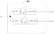
- FIG. 2 shows a block of the magnetic flux gain calculator 7. As shown in FIG.
- the magnetic flux gain calculator 7 is composed of a q-axis magnetic flux gain calculator 71 and a d-axis magnetic flux gain calculator 72 .
- a q-axis magnetic flux gain calculator 71 calculates a sine function of the phase estimated value according to (Equation 2) using the phase estimated value ⁇ dc and outputs a q-axis magnetic flux gain G q ( ⁇ dc ).
- the d-axis magnetic flux gain calculator 72 uses the phase estimated value ⁇ dc to calculate the sine function of the phase estimated value according to (Equation 3) and outputs the d-axis magnetic flux gain G q ( ⁇ dc ).
- N is the order and is a natural number.
- a block of the vector control calculation unit 8 is shown in FIG. First, the d-axis voltage command value of the vector control calculation unit 8 will be described.
- the induced voltage coefficient K e * 81 of the permanent magnet motor 1 and the q-axis magnetic flux gain G q ( ⁇ dc ) are input to the multiplier 82 .
- the output of the multiplication section 82 is input to the multiplication section 83 together with the frequency estimation value ⁇ dc , and its output becomes the command value e dc * of the d-axis induced voltage shown in (Equation 4).
- the frequency estimated value ⁇ dc is used as the input of the multiplier 83, but instead of the frequency estimated value ⁇ dc , the frequency command value ⁇ r * is used as the input of the multiplier 83 and multiplied by the output of the multiplier 82.
- the induced voltage coefficient K e * 81 is a constant value and is not induced voltage data that changes according to the rotational position. Further, the calculation unit 84 calculates the set value R * of the winding resistance, which is the electric circuit parameter of the permanent magnet motor 1, the set value Lq* of the inductance of the q -axis, the current command value id * of the d -axis, the current of the q-axis . Using the command value i q * and the estimated frequency value ⁇ dc , the d-axis voltage command value v dc0 * is calculated according to (Equation 5).
- the output v dc0 * of the calculation unit 84 is input to the addition unit 85 together with the d-axis induced voltage command value e dc * , and the output of the addition unit 85 is the d-axis voltage command value reference value v dc * .
- T acr Response time constant of current control
- the induced voltage coefficient K e * 81 of the permanent magnet motor 1 and the d-axis magnetic flux gain G d ( ⁇ dc ) are input to the multiplier 87 .
- the output of the multiplier 87 is input to the multiplier 88 together with the frequency estimate ⁇ dc .
- the output of the multiplication unit 88 is the q-axis induced voltage command value e qc * shown in (Equation 7).
- the frequency estimated value ⁇ dc is used as the input of the multiplier 88, but instead of the frequency estimated value ⁇ dc , the frequency command value ⁇ r * is used as the input of the multiplier 88 and multiplied by the output of the multiplier 87.
- the calculation unit 86 calculates the set value R * of the winding resistance, which is the electric circuit parameter of the permanent magnet motor 1, the set value Ld * of the d -axis inductance, the d -axis current command value id * , the q-axis current Using the command value i q * and the estimated frequency value ⁇ dc , the q-axis voltage command value v qc0 * is calculated according to (Equation 8).
- the output v qc0 * of the calculator 86 is input to the adder 89 together with the q-axis induced voltage command value e qc * .
- the output of the adder 89 is the reference value v qc * of the q-axis voltage command value shown in (Equation 9).
- K pd d-axis current control proportional gain
- K id d-axis current control integral gain
- K pq q-axis current control proportional gain
- K iq q-axis current control integral gain
- the phase error estimation calculation unit 9 calculates the d-axis and q -axis voltage command values vdc **, vqc** , current detection values idc , iqc , and electric circuit parameters (R * , Lq * ), and the estimated value ⁇ c of the phase error is calculated according to the extended induced voltage formula (Equation 12) based on the estimated frequency ⁇ dc .
- the frequency and phase estimation calculator 10 will be described. P (proportional) + I (integral) control calculation so that the estimated value ⁇ c of the phase error follows the command value ⁇ c * , the frequency estimated value ⁇ dc according to (Equation 13), and the I control calculation according to (Equation 14) A phase estimate ⁇ dc is calculated respectively.
- Kp pll proportional gain of PLL control
- Ki pll integral gain of PLL control
- the upper part shows the command values e dc * and e qc * for the d-axis and q-axis induced voltages
- the middle part shows the u-phase rectangular wave induced voltage e u and the u-phase induced voltage equivalent e u *
- the u -phase alternating current iu is not a sinusoidal current, but a distorted current in which the fifth and seventh harmonics are superimposed.
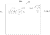
- the constant "1" is set in the setting section 72a9.
- the upper part shows the command values e dc * and e qc * for the d-axis and q-axis induced voltages
- the middle part shows the u-phase square-wave induced voltage e u and the u-phase induced voltage corresponding to the command value e u *
- the lower part shows the u-phase AC current i u .
- G q ( ⁇ dc ) is the block in FIG. 5
- G d ( ⁇ dc ) is the block in FIG.
- the d-axis and q-axis induced voltage command values e dc * and e qc * include harmonic components up to the 24th order, and the induced voltage command value e u * is different from the sine wave containing harmonics. It can be seen that the u-phase AC current i u is a sinusoidal current. It can be seen that the effect of the present invention is clear. In the case of FIG. 4, the d-axis induced voltage command value e dc * is zero, but the d-axis induced voltage command value e dc * is not zero as in FIG. One of the characteristics is that it has a shape that includes (sawtooth wave).
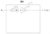
- N 1 in (Formula 2).
- This signal becomes G q ( ⁇ dc ).
- the constant "1" is set in the setting section 72b3.
- the upper part shows the command values e dc * and e qc * for the d-axis and q-axis induced voltages
- the middle part shows the u-phase rectangular wave induced voltage e u and the u-phase induced voltage command value e u *
- the lower part shows the u-phase AC current i u .
- G q ( ⁇ dc ) is calculated by the block shown in FIG. 8
- G d ( ⁇ dc ) is calculated by the block shown in FIG.
- the d-axis and q-axis induced voltage command values e dc * and e qc * contain sixth-order harmonic components, and the induced voltage command value equivalent e u * has a waveform that differs from a sine wave.
- u -phase alternating current iu is slightly distorted compared to the sine wave, but it is clear that the effect of the present invention is clear.
- the current of the magnet motor can be made into a sine wave by using a general-purpose controller or the like without having induced voltage data.
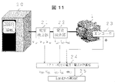
- a voltage detector 21 and a current detector 22 are attached to a power conversion device 20 that drives the magnet motor 1 , and an encoder 23 is attached to the shaft of the magnet motor 1 .
- the vector voltage/current component calculation unit 24 stores three-phase AC voltage detection values (v uc , v vc , v wc ) and three-phase AC current detection values (i uc , i vc , i wc ) and the detected position value ⁇ , which is the output of the encoder, are input, and the vector voltage components v dcc , v qcc , the vector current components i dcc , i qcc , and the detected value ⁇ rc obtained by differentiating the position ⁇ are calculated. do.
- the waveform observation unit 25 calculates the induced voltages e dc ⁇ and e qc ⁇ on the d-axis and q-axis using (Equation 16).
- FIG. 12 is a system configuration diagram having a power conversion device and a magnet motor according to the second embodiment.
- the dq-axis voltage command value of the rotating seat coordinate is corrected, but this embodiment corrects the UVW voltage command value of the fixed coordinate.
- FIG. 3 shows a configuration in which the induced voltage coefficient K e * 81, the multiplier 82, the multiplier 83, the adder 85, the multiplier 87, the multiplier 88, and the adder 89 are removed from the vector control calculator 8 in FIG. 12 vector control calculation units 8 are formed.
- Reference numeral 12 denotes a coordinate conversion unit for converting from rotating coordinates to fixed coordinates
- 13 denotes an addition unit.
- the coordinate conversion unit 12 converts the q-axis magnetic flux gain G q ( ⁇ dc ) and the d-axis magnetic flux gain G d ( ⁇ dc ) to the d-axis and q-axis
- the induced voltage command values e dc * and e qc * are calculated.
- the coordinate transformation unit 12 calculates command values e u * , e v * , e prints w * .
- the d-axis and q-axis induced voltage command values e dc * and e qc * are converted into 3-phase induced voltage command values e u * , ev * and e w * , and the three-phase induced voltage Correct the voltage command value.
- a sinusoidal current can be realized as in the first embodiment.
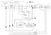
- FIG. 13 is a system configuration diagram having a power converter and a magnet motor according to the third embodiment.
- Magnet motor 1 power converter 2, DC power supply 3, current detector 4, coordinate conversion unit 5, speed control calculation unit 6, magnetic flux gain calculation unit 7, vector control calculation unit 8, phase error estimation calculation unit 9 in FIG. , the frequency and phase estimation calculation unit 10, and the coordinate transformation unit 11 are the same as in FIG. 14 is an IOT (Internet of Things) controller capable of executing machine learning.
- IOT Internet of Things
- parameters such as the drive mode (rectangular wave drive or sine wave drive) and the order N of (Formula 2) or (Formula 3) are set in the controller (control unit such as a microcomputer) of the power converter. Configuration.
- the control unit of the third embodiment sets the gain of the magnetic flux component on the q-axis to 0 and the gain of the magnetic flux component on the d-axis to 1 when receiving a sinusoidal drive instruction.
- the control unit When receiving a rectangular wave drive instruction, the control unit calculates and obtains the gain of the q-axis magnetic flux component as a sine function of the phase estimation value based on (Equation 2). Further, the control unit calculates the gain of the d-axis magnetic flux component as a sine function of the phase estimation value based on (Equation 3), and subtracts 1 from the calculation result.
- the control unit feeds back the voltage command values v dc ** , v qc ** , the current detection values i dc , i qc , and the phase error estimated value ⁇ c to the higher-level IOT controller 14 .
- the IOT controller 14 analyzes signals such as the voltage command values v dc ** and v qc ** , the current detection values i dc and i qc , and the phase error estimated value ⁇ c by machine learning, and based on the machine learning, the control unit resets the drive mode and the order N in the controller of the power converter 2 .
- a sinusoidal current can be realized as in the first embodiment.
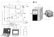
- FIG. 14 is a system configuration diagram having a power conversion device and a magnet motor according to the fourth embodiment. This embodiment is an application of this embodiment to a magnet motor drive system.
- the magnet motor 1, which is a component of FIG. 1, is driven by a power conversion device 20.
- the power conversion device 20 includes the coordinate conversion unit 5, the speed control calculation unit 6, the magnetic flux gain calculation unit 7, the vector control calculation unit 8, the phase error estimation calculation unit 9, the frequency and phase estimation calculation unit 10, and the coordinate conversion unit 10 shown in FIG.
- the unit 11 is implemented as software 20a.
- the power converter 20 has the power converter 2, the DC power supply 3, and the current detector 4 of FIG. 1 implemented as hardware.
- the "drive mode" 26 for setting the rectangular wave drive or the sine wave drive of the software 20a (Equation 2) and ( The "order N” 27 of equation 3) can be set and changed.
- the current of the magnet motor which is a square-wave induced voltage
- driving mode and “N” may be set on a field bus such as a programmable logic controller, a local area network connected to a computer, or an IOT controller.
- the calculation results of the magnetic flux gain calculation units 71a2, 71a4, 71a6 and 71a8 in FIG. 5 and the calculation units 72a2, 72a4, 72a6 and 72a8 in FIG. 6 are constants.
- the first to fourth embodiments have been applied to position sensorless control, but may be applied to vector control in which an encoder is attached to the shaft of the magnet motor 1.
- the voltage correction values ⁇ v dc and ⁇ v qc are created from the current command values i d * and i q * and the current detection values i dc and i qc , and the voltage correction values and the vector
- the calculation shown in (Equation 11) for adding the voltage reference value for control was performed.
- the vector control calculation shown in (Equation 18) may be performed.
- K pd1 dc-axis current control proportional gain
- K id1 dc -axis current control integral gain
- K pq1 q c -axis current control proportional gain
- K iq1 q c - axis current control integral Gain
- T d d-axis electrical time constant (L d /R)
- T q q-axis electrical time constant (L q /R)
- the voltage correction value ⁇ v d_p * of the d-axis proportional calculation component and the voltage of the d-axis integral calculation component used for vector control calculation The correction value ⁇ v d_i * , the voltage correction value ⁇ v q_p * of the q-axis proportional calculation component, and the voltage correction value ⁇ v q_i * of the q-axis integral calculation component are created by (Equation 19). Then, the vector control calculation shown in (Equation 20) using the frequency estimated value ⁇ dc and the electric circuit parameters of the magnet motor 1 may be performed.
- K pd2 d-axis current control proportional gain
- K id2 d-axis current control integral gain
- K pq2 q-axis current control proportional gain
- K iq2 q-axis current control integral gain
- the switching elements constituting the power converter 2 may be Si (silicon) semiconductor elements, SiC (silicon carbide), GaN (gallium nitride), or the like. It may be a wide bandgap semiconductor device.
- SYMBOLS 1 Magnet motor, 2... Power converter, 3... DC power supply, 4... Current detector, 5... Coordinate conversion part, 6... Speed control calculation part, 7... Magnetic flux gain calculation part, 8... Vector control calculation part, 9 ... phase error estimation calculation unit 10 ... frequency and phase estimation calculation unit 11 ... coordinate conversion unit 12 ... coordinate conversion unit 13 ... addition unit 14 ... IOT controller 20 ... power conversion device 20a ... power conversion device 20b...Digital operator of the power conversion device 21...Voltage detector 22...Current detector 23...Encoder 24...Vector current component calculation unit 25...Each part current waveform observation unit 26...Control Mode, 27... N (order), 28... Personal computer, 29... Tablet, 30... Smart phone, id * ...
Landscapes
- Engineering & Computer Science (AREA)
- Power Engineering (AREA)
- Artificial Intelligence (AREA)
- Evolutionary Computation (AREA)
- Control Of Ac Motors In General (AREA)
- Control Of Motors That Do Not Use Commutators (AREA)
Abstract
Description
前記電力変換器を制御する制御部を有し、
前記制御部は、
前記磁石モータの位相に応じて変化するq軸の磁束成分のゲインを演算し、
誘起電圧係数の設定値と、周波数推定値あるいは周波数指令値と、q軸の前記磁束成分のゲインとに基づいて、d軸の誘起電圧の指令値を演算する電力変換装置である。
座標変換部5は、3相の交流電流iu、iv、iwの検出値iuc、ivc、iwcと位相推定値θdcからd軸およびq軸の電流検出値idc、iqcを出力する。

Ksp:速度制御の比例ゲイン、Ksi:速度制御の積分ゲイン、Pm:極対数、
Ke:誘起電圧係数、Ld:d軸インダクタンス、Lq:q軸インダクタンス、
*:設定値、sはラプラス演算子
図2は、磁束ゲイン演算部7のブロックを示す。磁束ゲイン演算部7は、q軸の磁束ゲイン演算部71とd軸の磁束ゲイン演算部72より構成される。


Kpd:d軸の電流制御の比例ゲイン、Kid:d軸の電流制御の積分ゲイン
Kpq:q軸の電流制御の比例ゲイン、Kiq:q軸の電流制御の積分ゲイン


位相誤差の推定値Δθcを指令値Δθc *に追従するようP(比例)+I(積分)制御演算により、(数式13)に従い周波数推定値ωdcを、I制御演算により(数式14)に従い位相推定値θdcをそれぞれ演算する。

Kppll:PLL制御の比例ゲイン、Kipll:PLL制御の積分ゲイン

図4は、d軸およびq軸の磁束ゲインを、それぞれGq(θdc)=0、Gd(θdc)=1とした場合の制御特性1を示す。誘起電圧が矩形波である磁石モータ1を駆動したシミュレーション結果である。

各部波形の観測部25では、(数式16)を用いてd軸およびq軸の誘起電圧edc ^、eqc ^を計算する。

実施例1は、回転座座標のd-q軸の電圧指令値を修正したが、本実施例は固定座標のU-V―Wの電圧指令値を修正する実施例である。
本実施例は、磁石モータ駆動システムに本実施例を適用したものである。


Kpd1:dc軸の電流制御の比例ゲイン、Kid1:dc軸の電流制御の積分ゲイン、Kpq1:qc軸の電流制御の比例ゲイン、Kiq1:qc軸の電流制御の積分ゲイン、Td:d軸の電気時定数(Ld/R)、Tq:q軸の電気時定数(Lq/R)

Kpd2:d軸の電流制御の比例ゲイン、Kid2:d軸の電流制御の積分ゲイン、Kpq2:q軸の電流制御の比例ゲイン、Kiq2:q軸の電流制御の積分ゲイン


Claims (10)
- 磁石モータの出力周波数と出力電圧と出力電流を可変にする信号を前記磁石モータに出力する電力変換器と、
前記電力変換器を制御する制御部を有し、
前記制御部は、
前記磁石モータの位相に応じて変化するq軸の磁束成分のゲインを演算し、
誘起電圧係数の設定値と、周波数推定値あるいは周波数指令値と、q軸の前記磁束成分のゲインとに基づいて、d軸の誘起電圧の指令値を演算する電力変換装置。 - 請求項1に記載の電力変換装置において、
前記制御部は、
前記磁石モータの位相に応じて変化するd軸の磁束成分のゲインを演算し、
誘起電圧係数の設定値と、周波数推定値あるいは周波数指令値と、d軸の前記磁束成分のゲインとに基づいて、q軸の誘起電圧の指令値を演算する電力変換装置。 - 請求項1に記載の電力変換装置において、
前記制御部は、
d軸の前記誘起電圧の指令値と、位相推定値とに基づいて、3相の誘起電圧の指令値を演算する電力変換装置。 - 請求項2に記載の電力変換装置において、
前記制御部は、
d軸の前記誘起電圧の指令値と、q軸の前記誘起電圧の指令値と、位相推定値とに基づいて、3相の誘起電圧の指令値を演算する電力変換装置。 - 請求項1に記載の電力変換装置において、
前記制御部は、
q軸の前記磁束成分のゲインは、位相推定値の正弦関数として演算する電力変換装置。 - 請求項2に記載の電力変換装置において、
前記制御部は、
d軸の前記磁束成分のゲインは、位相推定値の正弦関数として演算し、その演算結果を1から減算する電力変換装置。 - 請求項2に記載の電力変換装置において、
前記制御部は、
前記磁石モータの駆動を正弦波駆動とするか、矩形波駆動とするかの指示を受け、
正弦波駆動の指示を受けた場合には、
q軸の前記磁束成分のゲインを0とし、d軸の前記磁束成分のゲインを1とし、
矩形波駆動の指示を受けた場合には、
q軸の前記磁束成分のゲインは位相推定値の正弦関数として演算して求め、d軸の前記磁束成分のゲインは、位相推定値の正弦関数として演算して、その演算結果を1から減算して求める電力変換装置。 - 請求項2に記載の電力変換装置において、
前記制御部は、
前記磁石モータが矩形波駆動である選択の指示を受けた場合には、
位相推定値の正弦関数における次数Nの選択の指示を受けて、
前記次数Nに基づいて、q軸の前記磁束成分のゲインおよびd軸の前記磁束成分のゲインを演算する電力変換装置。 - 請求項2に記載の電力変換装置において、
前記制御部は、
電圧指令値および電流検出値と、位相誤差の推定値や推定周波数を、上位装置に解析のためにフィードバックし、
q軸の前記磁束成分のゲインもしくはd軸の前記磁束成分のゲインを演算するのに必要な位相推定値の正弦関数における次数Nを、前記上位装置からの解析に基づいて自動設定する電力変換装置。 - 請求項1に記載の電力変換装置において、
前記制御部は、
q軸の前記磁束成分のゲインもしくはd軸の前記磁束成分のゲインを演算するのに必要な位相推定値の正弦関数における次数N、または前記磁石モータの駆動を正弦波駆動とするか、矩形波駆動とするかを、デジタル・オペレータやパーソナル・コンピュータあるいはタブレット、スマートフォン機器から設定・変更できる電力変換装置。
Priority Applications (3)
| Application Number | Priority Date | Filing Date | Title |
|---|---|---|---|
| EP21948484.7A EP4366152A4 (en) | 2021-06-29 | 2021-11-10 | POWER CONVERTER |
| US18/273,844 US12334847B2 (en) | 2021-06-29 | 2021-11-10 | Power converter apparatus |
| CN202180090523.8A CN116746049A (zh) | 2021-06-29 | 2021-11-10 | 电力转换装置 |
Applications Claiming Priority (2)
| Application Number | Priority Date | Filing Date | Title |
|---|---|---|---|
| JP2021-107665 | 2021-06-29 | ||
| JP2021107665A JP2023005629A (ja) | 2021-06-29 | 2021-06-29 | 電力変換装置 |
Publications (1)
| Publication Number | Publication Date |
|---|---|
| WO2023276181A1 true WO2023276181A1 (ja) | 2023-01-05 |
Family
ID=84691096
Family Applications (1)
| Application Number | Title | Priority Date | Filing Date |
|---|---|---|---|
| PCT/JP2021/041409 Ceased WO2023276181A1 (ja) | 2021-06-29 | 2021-11-10 | 電力変換装置 |
Country Status (5)
| Country | Link |
|---|---|
| US (1) | US12334847B2 (ja) |
| EP (1) | EP4366152A4 (ja) |
| JP (1) | JP2023005629A (ja) |
| CN (1) | CN116746049A (ja) |
| WO (1) | WO2023276181A1 (ja) |
Cited By (2)
| Publication number | Priority date | Publication date | Assignee | Title |
|---|---|---|---|---|
| WO2024224659A1 (ja) * | 2023-04-26 | 2024-10-31 | 株式会社日立産機システム | 電力変換装置 |
| TWI916716B (zh) | 2023-04-26 | 2026-03-01 | 日商日立產機系統股份有限公司 | 電力轉換裝置 |
Citations (5)
| Publication number | Priority date | Publication date | Assignee | Title |
|---|---|---|---|---|
| JP2003199390A (ja) | 2001-12-28 | 2003-07-11 | Toshiba Corp | ベクトル制御インバータ装置 |
| JP2009017676A (ja) * | 2007-07-04 | 2009-01-22 | Aisin Seiki Co Ltd | 同期モータの制御装置及び制御方法 |
| JP2014166082A (ja) * | 2013-02-27 | 2014-09-08 | Hitachi Appliances Inc | モータ制御装置、およびそれを用いた空気調和機 |
| JP2016201911A (ja) * | 2015-04-10 | 2016-12-01 | 株式会社ミツバ | モータ駆動装置及びモータ駆動装置の制御方法 |
| JP2020005404A (ja) * | 2018-06-28 | 2020-01-09 | 株式会社日立産機システム | 電力変換装置 |
Family Cites Families (7)
| Publication number | Priority date | Publication date | Assignee | Title |
|---|---|---|---|---|
| JP5259241B2 (ja) * | 2008-04-23 | 2013-08-07 | 株式会社東芝 | モータ制御装置,モータ駆動システム,洗濯機,空調機,永久磁石モータの着磁量変更方法 |
| JP5417195B2 (ja) * | 2010-01-19 | 2014-02-12 | 国産電機株式会社 | 永久磁石モータのトルクリプル抑制制御装置、電動パワーステアリングシステム |
| US9525376B2 (en) * | 2014-05-13 | 2016-12-20 | Gbox, Llc | Wound field synchronous machine with resonant field exciter |
| CN107431452B (zh) | 2015-04-10 | 2020-03-31 | 株式会社美姿把 | 电动机驱动装置以及电动机驱动装置的控制方法 |
| JP6457472B2 (ja) * | 2016-12-14 | 2019-01-23 | ファナック株式会社 | 制御システム及び機械学習装置 |
| JP7489899B2 (ja) * | 2019-10-18 | 2024-05-24 | 株式会社安川電機 | 事象推定システム及び事象推定方法 |
| JP7095760B1 (ja) * | 2021-01-14 | 2022-07-05 | 株式会社安川電機 | 制御装置、磁束推定装置及び磁束推定方法 |
-
2021
- 2021-06-29 JP JP2021107665A patent/JP2023005629A/ja active Pending
- 2021-11-10 CN CN202180090523.8A patent/CN116746049A/zh active Pending
- 2021-11-10 EP EP21948484.7A patent/EP4366152A4/en not_active Withdrawn
- 2021-11-10 WO PCT/JP2021/041409 patent/WO2023276181A1/ja not_active Ceased
- 2021-11-10 US US18/273,844 patent/US12334847B2/en active Active
Patent Citations (5)
| Publication number | Priority date | Publication date | Assignee | Title |
|---|---|---|---|---|
| JP2003199390A (ja) | 2001-12-28 | 2003-07-11 | Toshiba Corp | ベクトル制御インバータ装置 |
| JP2009017676A (ja) * | 2007-07-04 | 2009-01-22 | Aisin Seiki Co Ltd | 同期モータの制御装置及び制御方法 |
| JP2014166082A (ja) * | 2013-02-27 | 2014-09-08 | Hitachi Appliances Inc | モータ制御装置、およびそれを用いた空気調和機 |
| JP2016201911A (ja) * | 2015-04-10 | 2016-12-01 | 株式会社ミツバ | モータ駆動装置及びモータ駆動装置の制御方法 |
| JP2020005404A (ja) * | 2018-06-28 | 2020-01-09 | 株式会社日立産機システム | 電力変換装置 |
Non-Patent Citations (1)
| Title |
|---|
| See also references of EP4366152A4 |
Cited By (2)
| Publication number | Priority date | Publication date | Assignee | Title |
|---|---|---|---|---|
| WO2024224659A1 (ja) * | 2023-04-26 | 2024-10-31 | 株式会社日立産機システム | 電力変換装置 |
| TWI916716B (zh) | 2023-04-26 | 2026-03-01 | 日商日立產機系統股份有限公司 | 電力轉換裝置 |
Also Published As
| Publication number | Publication date |
|---|---|
| US20240079982A1 (en) | 2024-03-07 |
| CN116746049A (zh) | 2023-09-12 |
| EP4366152A1 (en) | 2024-05-08 |
| US12334847B2 (en) | 2025-06-17 |
| EP4366152A4 (en) | 2025-04-16 |
| JP2023005629A (ja) | 2023-01-18 |
Similar Documents
| Publication | Publication Date | Title |
|---|---|---|
| CN104335476B (zh) | 电动机的控制装置以及电动机的控制方法 | |
| JP6367332B2 (ja) | インバータ制御装置及びモータ駆動システム | |
| CN101647186B (zh) | 电力变换装置 | |
| CN109874396B (zh) | 逆变器控制装置以及电动机驱动系统 | |
| JP4988329B2 (ja) | 永久磁石モータのビートレス制御装置 | |
| JP6617500B2 (ja) | 電動パワーステアリング制御方法、電動パワーステアリング制御装置、電動パワーステアリング装置および車両 | |
| US11424707B2 (en) | Power conversion apparatus | |
| JP6374037B2 (ja) | モータ制御装置 | |
| US20040183496A1 (en) | Motor control apparatus and motor control method | |
| KR101485989B1 (ko) | 모터 제어 장치 | |
| JP6473992B2 (ja) | モータ制御装置及び発電機制御装置 | |
| CN116830450A (zh) | 电力转换装置 | |
| CN106257822A (zh) | 马达控制装置、磁通指令生成装置和磁通指令生成方法 | |
| JP2023005629A (ja) | 電力変換装置 | |
| JP6593685B2 (ja) | モータ制御装置及び発電機制御装置 | |
| JP6848680B2 (ja) | 同期電動機の制御装置 | |
| KR20180020268A (ko) | 전동기 구동 장치, 방법 및 전동기 | |
| JP7251424B2 (ja) | インバータ装置及びインバータ装置の制御方法 | |
| JP2013188074A (ja) | 誘導モータの制御装置および制御方法 | |
| JP4479371B2 (ja) | 回転位置角推定方法及び回転位置角推定装置並びにインバータ制御方法及びインバータ制御装置 | |
| JP5456873B1 (ja) | 同期機制御装置 | |
| JP7413926B2 (ja) | 制御装置及び電力変換装置 | |
| EP4686078A1 (en) | Motor control device | |
| CN120642203A (zh) | 电力转换装置 | |
| CN118451648A (zh) | 功率转换装置 |
Legal Events
| Date | Code | Title | Description |
|---|---|---|---|
| 121 | Ep: the epo has been informed by wipo that ep was designated in this application |
Ref document number: 21948484 Country of ref document: EP Kind code of ref document: A1 |
|
| WWE | Wipo information: entry into national phase |
Ref document number: 202180090523.8 Country of ref document: CN |
|
| WWE | Wipo information: entry into national phase |
Ref document number: 18273844 Country of ref document: US |
|
| WWE | Wipo information: entry into national phase |
Ref document number: 2021948484 Country of ref document: EP |
|
| NENP | Non-entry into the national phase |
Ref country code: DE |
|
| ENP | Entry into the national phase |
Ref document number: 2021948484 Country of ref document: EP Effective date: 20240129 |
|
| WWG | Wipo information: grant in national office |
Ref document number: 18273844 Country of ref document: US |
|
| WWW | Wipo information: withdrawn in national office |
Ref document number: 2021948484 Country of ref document: EP |