WO2023276285A1 - 侵入検出システム - Google Patents
侵入検出システム Download PDFInfo
- Publication number
- WO2023276285A1 WO2023276285A1 PCT/JP2022/009855 JP2022009855W WO2023276285A1 WO 2023276285 A1 WO2023276285 A1 WO 2023276285A1 JP 2022009855 W JP2022009855 W JP 2022009855W WO 2023276285 A1 WO2023276285 A1 WO 2023276285A1
- Authority
- WO
- WIPO (PCT)
- Prior art keywords
- work machine
- point cloud
- data
- machine
- work
- Prior art date
- Legal status (The legal status is an assumption and is not a legal conclusion. Google has not performed a legal analysis and makes no representation as to the accuracy of the status listed.)
- Ceased
Links
Images


Classifications
-
- E—FIXED CONSTRUCTIONS
- E02—HYDRAULIC ENGINEERING; FOUNDATIONS; SOIL SHIFTING
- E02F—DREDGING; SOIL-SHIFTING
- E02F9/00—Component parts of dredgers or soil-shifting machines, not restricted to one of the kinds covered by groups E02F3/00 - E02F7/00
- E02F9/26—Indicating devices
- E02F9/261—Surveying the work-site to be treated
-
- G—PHYSICS
- G08—SIGNALLING
- G08B—SIGNALLING SYSTEMS, e.g. PERSONAL CALLING SYSTEMS; ORDER TELEGRAPHS; ALARM SYSTEMS
- G08B13/00—Burglar, theft or intruder alarms
- G08B13/18—Actuation by interference with heat, light, or radiation of shorter wavelength; Actuation by intruding sources of heat, light, or radiation of shorter wavelength
- G08B13/189—Actuation by interference with heat, light, or radiation of shorter wavelength; Actuation by intruding sources of heat, light, or radiation of shorter wavelength using passive radiation detection systems
- G08B13/194—Actuation by interference with heat, light, or radiation of shorter wavelength; Actuation by intruding sources of heat, light, or radiation of shorter wavelength using passive radiation detection systems using image scanning and comparing systems
- G08B13/196—Actuation by interference with heat, light, or radiation of shorter wavelength; Actuation by intruding sources of heat, light, or radiation of shorter wavelength using passive radiation detection systems using image scanning and comparing systems using television cameras
- G08B13/19634—Electrical details of the system, e.g. component blocks for carrying out specific functions
-
- G—PHYSICS
- G01—MEASURING; TESTING
- G01C—MEASURING DISTANCES, LEVELS OR BEARINGS; SURVEYING; NAVIGATION; GYROSCOPIC INSTRUMENTS; PHOTOGRAMMETRY OR VIDEOGRAMMETRY
- G01C15/00—Surveying instruments or accessories not provided for in groups G01C1/00 - G01C13/00
- G01C15/002—Active optical surveying means
-
- G—PHYSICS
- G06—COMPUTING OR CALCULATING; COUNTING
- G06T—IMAGE DATA PROCESSING OR GENERATION, IN GENERAL
- G06T7/00—Image analysis
-
- G—PHYSICS
- G06—COMPUTING OR CALCULATING; COUNTING
- G06T—IMAGE DATA PROCESSING OR GENERATION, IN GENERAL
- G06T7/00—Image analysis
- G06T7/70—Determining position or orientation of objects or cameras
-
- G—PHYSICS
- G08—SIGNALLING
- G08B—SIGNALLING SYSTEMS, e.g. PERSONAL CALLING SYSTEMS; ORDER TELEGRAPHS; ALARM SYSTEMS
- G08B13/00—Burglar, theft or intruder alarms
- G08B13/18—Actuation by interference with heat, light, or radiation of shorter wavelength; Actuation by intruding sources of heat, light, or radiation of shorter wavelength
- G08B13/189—Actuation by interference with heat, light, or radiation of shorter wavelength; Actuation by intruding sources of heat, light, or radiation of shorter wavelength using passive radiation detection systems
- G08B13/194—Actuation by interference with heat, light, or radiation of shorter wavelength; Actuation by intruding sources of heat, light, or radiation of shorter wavelength using passive radiation detection systems using image scanning and comparing systems
- G08B13/196—Actuation by interference with heat, light, or radiation of shorter wavelength; Actuation by intruding sources of heat, light, or radiation of shorter wavelength using passive radiation detection systems using image scanning and comparing systems using television cameras
- G08B13/19678—User interface
- G08B13/19682—Graphic User Interface [GUI] presenting system data to the user, e.g. information on a screen helping a user interacting with an alarm system
-
- E—FIXED CONSTRUCTIONS
- E02—HYDRAULIC ENGINEERING; FOUNDATIONS; SOIL SHIFTING
- E02F—DREDGING; SOIL-SHIFTING
- E02F3/00—Dredgers; Soil-shifting machines
- E02F3/04—Dredgers; Soil-shifting machines mechanically-driven
- E02F3/28—Dredgers; Soil-shifting machines mechanically-driven with digging tools mounted on a dipper- or bucket-arm, i.e. there is either one arm or a pair of arms, e.g. dippers, buckets
- E02F3/36—Component parts
- E02F3/42—Drives for dippers, buckets, dipper-arms or bucket-arms
- E02F3/43—Control of dipper or bucket position; Control of sequence of drive operations
- E02F3/435—Control of dipper or bucket position; Control of sequence of drive operations for dipper-arms, backhoes or the like
Definitions
- the present invention relates to an intrusion detection system that detects when an object has entered a work area.
- Patent Document 1 discloses an interference prevention device that sets first to sixth areas around a working machine and determines the presence or absence of a person in each of the first to sixth areas.
- the presence or absence of a person is determined based on information from an object sensor provided in a working machine.
- the work machine that is working in the work area and the intrusion into the work area are detected from outside the work area.
- a working machine that is working in the work area may be mistakenly detected as an object that has entered the work area.
- An object of the present invention is to provide an intrusion detection system that can accurately detect that an object other than a working machine that is working in the work area has entered the work area.
- the intrusion detection system includes a machine position acquisition unit that acquires a position in a predetermined coordinate system of a work machine that is working inside a work area, and a position inside and outside the work area from a reference point provided outside the work area.
- a point cloud data acquisition unit that acquires point cloud data indicating the distance to an object that is positioned on the object; a position calculation unit that calculates the position of each point of the point cloud data in the coordinate system; a specifying unit for specifying a portion corresponding to the working machine from the point cloud data as specifying data based on the position and the position of each point of the point cloud data; a detection unit that detects that another object different from the working machine has entered the work area based on the remaining point cloud data other than the data.
- FIG. 1 is a side view of a working machine according to each embodiment of the present invention.
- FIG. 2 is a diagram showing how the work machine according to each embodiment of the present invention is working in the work area.
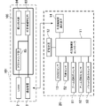
- FIG. 3 is a block diagram of an intrusion detection system and working machine according to the first embodiment of the present invention.
- FIG. 4 is a diagram showing an example of point cloud data acquired by LiDAR.
- FIG. 5 is a diagram showing an example of the three-dimensional shape data of the work machine calculated by the three-dimensional shape data calculator.
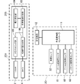
- FIG. 6 is a block diagram of an intrusion detection system and working machine according to a second embodiment of the present invention.
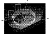
- FIG. 7 is a diagram showing an example of cluster point clouds positioned inside and outside the work area.
- FIG. 8 is a block diagram of an intrusion detection system and working machine according to a third embodiment of the present invention.
- FIG. 1 is a side view of work machine 20.
- the work machine 20 is a machine that performs work with an attachment 30, such as a hydraulic excavator.
- the working machine 20 has a machine main body 24 having a lower travel body 21 and an upper revolving body 22 , an attachment 30 and a cylinder 40 .
- the lower traveling body 21 is a part that allows the working machine 20 to travel, and includes, for example, crawlers.
- the upper revolving body 22 is rotatably attached to the upper part of the lower traveling body 21 via a revolving device 25 .
- a cab (driver's cab) 23 is provided in the front portion of the upper revolving body 22 .
- the attachment 30 is attached to the upper revolving body 22 so as to be vertically rotatable.
- the attachment 30 has a boom 31 , an arm 32 and a bucket 33 .
- the boom 31 is attached to the upper revolving body 22 so as to be vertically rotatable (up and down).
- the arm 32 is attached to the boom 31 so as to be vertically rotatable.
- the bucket 33 is attached to the arm 32 so as to be rotatable in the front-rear direction.
- the bucket 33 is a part for excavating, leveling, and scooping earth and sand (transported material).
- the material to be transported held by the bucket 33 is not limited to earth and sand, and may be stones or waste (industrial waste, etc.).
- the cylinder 40 can hydraulically rotate the attachment 30 .
- the cylinder 40 is a hydraulic telescopic cylinder.
- the cylinder 40 includes a boom cylinder 41 , an arm cylinder 42 and a bucket cylinder 43 .
- the boom cylinder 41 rotates the boom 31 with respect to the upper swing body 22 .
- a base end portion of the boom cylinder 41 is rotatably attached to the upper swing body 22 .
- a tip portion of the boom cylinder 41 is rotatably attached to the boom 31 .
- the arm cylinder 42 rotates the arm 32 with respect to the boom 31 .
- a base end of the arm cylinder 42 is rotatably attached to the boom 31 .
- a tip portion of the arm cylinder 42 is rotatably attached to the arm 32 .
- the bucket cylinder 43 rotates the bucket 33 with respect to the arm 32 .
- a base end of the bucket cylinder 43 is rotatably attached to the arm 32 .
- a tip portion of the bucket cylinder 43 is rotatably attached to a link member 34 rotatably attached to the bucket 33 .
- the working machine 20 also has an angle sensor 52 and an inclination sensor 60 .
- the angle sensor 52 detects the turning angle of the upper turning body 22 with respect to the lower traveling body 21 .
- the angle sensor 52 is, for example, an encoder, resolver, or gyro sensor.
- the turning angle of the upper turning body 22 when the front of the upper turning body 22 coincides with the front of the lower traveling body 21 is 0°.
- the tilt angle sensor 60 detects the orientation of the attachment 30 .
- the tilt angle sensor 60 includes a boom tilt angle sensor 61 , an arm tilt angle sensor 62 and a bucket tilt angle sensor 63 .
- a boom tilt angle sensor 61 is attached to the boom 31 and detects the attitude of the boom 31 .
- the boom tilt angle sensor 61 is a sensor that acquires the tilt angle of the boom 31 with respect to the horizontal line, and is, for example, a tilt (acceleration) sensor.
- the boom tilt angle sensor 61 may be a rotation angle sensor that detects the rotation angle of the boom foot pin (boom base end) or a stroke sensor that detects the stroke amount of the boom cylinder 41 .
- the arm tilt angle sensor 62 is attached to the arm 32 and detects the posture of the arm 32 .
- the arm tilt angle sensor 62 is a sensor that acquires the tilt angle of the arm 32 with respect to the horizontal line, and is, for example, a tilt (acceleration) sensor.
- the arm tilt angle sensor 62 may be a rotation angle sensor that detects the rotation angle of the arm connecting pin (arm proximal end) or a stroke sensor that detects the stroke amount of the arm cylinder 42 .
- the bucket tilt angle sensor 63 is attached to the link member 34 and detects the attitude of the bucket 33 .
- the bucket tilt angle sensor 63 is a sensor that acquires the tilt angle of the bucket 33 with respect to the horizontal line, and is, for example, a tilt (acceleration) sensor.
- the bucket tilt angle sensor 63 may be a rotation angle sensor that detects the rotation angle of the bucket connecting pin (bucket proximal end) or a stroke sensor that detects the stroke amount of the bucket cylinder 43 .
- FIG. 2 is a diagram showing the work machine 20 during work within the work area.
- work machine 20 performs work within work area 70 .
- the intrusion detection system 1 detects from outside the work area 70 that an object other than the working machine 20 that is working in the work area 70 has entered the work area 70 . In this case, it is necessary to distinguish between the work machine 20 that is working in the work area 70 and an object other than the work machine 20 that has entered the work area 70 .
- FIG. 3 is a block diagram of intrusion detection system 1 and work machine 20. As shown in FIG. As shown in FIG. 3 , the work machine 20 has a work machine controller 11 , a storage device 12 , a GNSS sensor 13 , and a work machine communication device 14 .
- Information regarding the turning angle (orientation) of the upper rotating body 22 with respect to the lower traveling body 21 detected by the angle sensor 52 is input to the work machine controller 11 . Further, information regarding the posture of the boom 31 detected by the boom tilt angle sensor 61 is input to the work implement controller 11 . In addition, information regarding the posture of the arm 32 detected by the arm tilt angle sensor 62 is input to the work machine controller 11 . Further, information regarding the posture of the bucket 33 detected by the bucket tilt angle sensor 63 is input to the work implement controller 11 .
- the storage device 12 stores information about the dimensions of the working machine 20 (the dimensions of the attachment 30) and the shape of the working machine 20 (the shape of the attachment 30).
- a GNSS (Global Navigation Satellite System) sensor (machine position acquisition unit) 13 acquires the position of the work machine 20 that is working within the work area.
- the GNSS sensor 13 is a positioning sensor and acquires the position (position information) of the work machine 20 in the global coordinate system (predetermined coordinate system).
- a positioning sensor such as a GPS sensor or a distance measuring sensor such as a total station may be used instead of the GNSS sensor 13 .
- the work machine side communication device 14 can communicate with the communication device 3 of the intrusion detection system 1, which will be described later.
- the intrusion detection system 1 has a LiDAR 2, a communication device 3, and a controller 5.
- the LiDAR (Light Detection and Ranging or Laser Imaging Detection and Ranging) (point cloud data acquisition unit) 2 is provided outside the work area 70 .
- the LiDAR 2 acquires point cloud data indicating the distance from the position (predetermined reference point) where the LiDAR 2 is attached to objects located inside and outside the work area 70 .
- FIG. 4 shows an example of point cloud data acquired by LiDAR2.
- the work area 70 is inside the cylinder illustrated in the middle of the figure.
- the communication device 3 can communicate with the work machine side communication device 14 of the work machine 20 .
- the communication device 3 receives information about the position of the work machine 20 acquired by the GNSS sensor 13 from the work machine 20 .
- Communication device 3 also receives information about the dimensions of work machine 20 (the dimensions of attachment 30 ) and the shape of work machine 20 (the shape of attachment 30 ) stored in storage device 12 from work machine 20 .
- the communication device 3 also detects the attitude of the work machine 20 (the attitude of the upper revolving body 22) detected by the angle sensor 52 and the tilt angle sensor 60 (the boom tilt angle sensor 61, the arm tilt angle sensor 62, and the bucket tilt angle sensor 63). , the attitude of the attachment 30 ) from the work machine 20 .
- the controller 5 has a coordinate transformation unit 81, a 3D model generation unit 82, a work machine identification unit 83, and an intrusion detection unit 84.
- a coordinate conversion unit (position calculation unit) 81 calculates the position of each point in the point cloud data acquired by the LiDAR 2 . Specifically, the coordinate conversion unit 81 converts the point cloud data in the global coordinate system using the position (coordinates) of the global coordinate system to which the LiDAR 2 is attached and the distance from the LiDAR 2 to each point of the point cloud data. The position (three-dimensional coordinates) of each point of is calculated.
- the 3D model generation unit (three-dimensional shape data calculation unit) 82 calculates the three-dimensional shape data of the work machine 20 based on the information on the dimensions, shape and orientation of the work machine 20 received by the communication device 3 .
- FIG. 5 shows an example of the three-dimensional shape data 75 of the work machine 20 calculated by the 3D model generator 82.
- the 3D model generation unit 82 may calculate the three-dimensional shape data of the work machine 20 using at least one of the information on the dimensions, shape, and orientation of the work machine 20, or may use all of them to calculate the three-dimensional shape data of the work machine 20. Three-dimensional shape data of the machine 20 may be calculated.
- the work machine identification unit (identification unit) 83 identifies the work machine from the point cloud data based on the position of the work machine 20 and the position of each point of the point cloud data in the global coordinate system. 20 is identified as specific data.
- the work machine identification unit (superimposition unit) 83 superimposes the three-dimensional shape data calculated by the 3D model generation unit 82 on the point cloud data at the position of the work machine 20 .
- the three-dimensional shape data 75 shown in FIG. 5 is superimposed on the point cloud data in the area surrounded by the dotted line 71.
- the work machine identifying unit 83 identifies a portion of the point cloud data where the three-dimensional shape data 75 overlaps as specific data. This makes it possible to know which part of the point cloud data corresponds to the working machine 20 .
- the intrusion detection unit (detection unit) 84 detects other points different from the work machine 20 in the work area based on the remaining point cloud data other than the specific data among the point cloud data acquired by the LiDAR 2.
- object intrusion Of the point cloud data, the portion corresponding to the work machine 20 working in the work area 70 is specified as the specific data, so the point cloud data other than the specified data intruding into the work area 70 is used as the work data. It is of an object other than the work machine 20 that is working within the area 70 . As a result, it is possible to accurately detect that an object other than the work machine 20 that is working in the work area 70 has entered the work area 70 .
- the part corresponding to the work machine 20 working in the work area 70 is specified as the specific data from the point cloud data. Intrusion of an object into the work area 70 is detected based on the point cloud data other than the specific data. Of the point cloud data, the portion corresponding to the work machine 20 working in the work area 70 is specified as the specific data, so the point cloud data other than the specified data intruding into the work area 70 is used as the work data. It is of an object other than the work machine 20 that is working within the area 70 . As a result, it is possible to accurately detect that an object other than the work machine 20 that is working in the work area 70 has entered the work area 70 .
- the mechanical position acquisition unit is a positioning sensor such as the GNSS sensor 13 or a ranging sensor.
- the position of the work machine 20 that is working within the work area 70 can be accurately obtained. Therefore, it is possible to accurately identify the specific data from the point cloud data.
- the portion where the three-dimensional shape data 75 of the work machine 20 overlap is specified as specific data.
- the specific data can be accurately specified.
- the 3D model generation unit 82 calculates the three-dimensional shape data 75 of the work machine 20, and the work machine identification unit 83 superimposes the calculated three-dimensional shape data 75 on the point cloud data. You specified specific data.
- the point cloud data acquired by the LiDAR 2 is clustered into cluster point clouds, and the cluster point cloud that matches the position of the work machine 20 is identified as specific data. Note that clustering is a type of unsupervised learning in machine learning, and is a method of grouping data based on similarity between data.
- FIG. 6 is a block diagram of intrusion detection system 101 and work machine 20 .
- the controller 105 of the intrusion detection system 101 has a clustering section 85 , a working machine identification section 83 and an intrusion detection section 84 .
- a clustering unit (clustering unit) 85 clusters the point cloud data acquired by the LiDAR 2 into a cluster point cloud.
- An example of a cluster point cloud 76 located inside and outside the work area 70 is shown in FIG.
- a clustering unit (position calculation unit) 85 uses the position (coordinates) of the global coordinate system to which the LiDAR 2 is attached and the distance from the LiDAR 2 to the cluster point cloud 76 to calculate the position of the cluster point cloud 76 in the global coordinate system. Calculate
- the work machine identification unit 83 identifies, as specific data, a cluster point group that matches the position of the work machine 20 acquired by the GNSS sensor 13 .
- the intrusion detection unit 84 detects that an object has entered the work area 70 based on the point cloud data other than the specific data.
- a cluster point group that matches the position of the work machine 20 is specified as specific data.
- the point cloud data By clustering the point cloud data into a cluster point cloud, it is possible to easily identify the specific data. Moreover, since it is not necessary to calculate the three-dimensional shape data 75 of the work machine 20, it is less susceptible to noise. Further, even for work machines 20 having different dimensions, the specific data can be preferably specified by clustering the point cloud data.
- the specific data is specified using the information about the position of the working machine 20 acquired by the GNSS sensor 13 .
- the position of the work machine 20 is acquired using the camera 4 (see FIG. 2).
- FIG. 8 is a block diagram of intrusion detection system 201 and work machine 20 .
- the intrusion detection system 201 has a LiDAR 2 , a camera 4 and a controller 205 .
- the controller 205 has a clustering section 85 , a machine position calculation section 86 , a working machine identification section 83 and an intrusion detection section 84 .
- the camera 4 and the machine position calculator 86 constitute a machine position acquirer.
- the upper revolving body 22 of the work machine 20 is provided with a mark 90 that enables (acquires) the position of the work machine 20 from outside the work machine 20 .
- the mark 90 is an AR marker.
- An AR marker is a sign on which identification information for designating an image to be superimposed and displayed on the physical space in AR (Augmented Reality) and its position is described.
- the mark 90 may be capable of acquiring information such as dimensions of the work machine 20 from the outside of the work machine 20 in addition to information on the position of the work machine 20 .
- the camera (imaging unit) 4 is provided outside the work area 70 .
- the camera 4 images the mark 90 provided on the upper swing body 22 .
- the machine position calculator (machine position calculator) 86 calculates the position of the work machine 20 based on the mark 90 captured by the camera 4 .
- the machine position calculator 86 calculates the position of the mark 90 in the global coordinate system using the position (coordinates) of the global coordinate system to which the camera 4 is attached and the distance from the camera 4 to the mark 90 .
- the marker position in the coordinate system with the camera 4 as the origin can be estimated.
- intrusion detection system 201 outside work machine 20
- work machine 20 there is no need for communication between intrusion detection system 201 (outside work machine 20 ) and work machine 20 . Therefore, the position of work machine 20 can be obtained even if work machine 20 is not equipped with a communication device.
- the clustering unit 85 clusters the point cloud data acquired by the LiDAR 2 into a cluster point cloud.
- the work machine identifying unit 83 identifies cluster points that match the position of the work machine 20 as specific data.
- the intrusion detection unit 84 detects that an object has entered the work area 70 based on the point cloud data other than the specific data. Others are the same as those of the second embodiment, so description thereof will be omitted.
- the position of the work machine 20 is calculated based on the mark 90 captured by the camera 4 . At this time, there is no need to communicate between the outside of work machine 20 and work machine 20 . Therefore, the position of work machine 20 can be obtained even if work machine 20 is not equipped with a communication device.
- the point cloud data acquisition unit exemplified by LiDAR2 is not limited to one provided outside the work area 70.
- the LiDAR 2 When the LiDAR 2 is mounted on a drone (not shown) and the drone is positioned above the work machine 20 , the LiDAR 2 may be inside the work area 70 or outside the work area 70 .
- the intrusion detection system includes a machine position acquisition unit that acquires the position of a work machine that is working inside a work area in a predetermined coordinate system, and a distance from a predetermined reference point to an object that is located inside or outside the work area.
- a point cloud data acquisition unit that acquires point cloud data indicating the point cloud data;
- a position calculation unit that calculates the position of each point of the point cloud data in the coordinate system; and the position of the work machine and the point cloud in the coordinate system.
- a specifying unit that specifies a portion corresponding to the working machine from the point cloud data as specified data based on the position of each point of the data; and remaining points of the point cloud data other than the specified data.
- a detection unit that detects that an object different from the work machine has entered the work area based on the group data.
- the mechanical position acquisition unit may be a positioning sensor or a ranging sensor.
- the work machine is provided with a mark for acquiring the position of the work machine from outside the work machine
- the machine position acquisition unit includes an imaging unit that captures an image of the mark;
- a machine position calculation unit that calculates the position of the work machine in the coordinate system based on the mark captured by the imaging unit.
- a three-dimensional shape data calculation unit for calculating three-dimensional shape data of the work machine based on at least one of dimensions, shape and attitude of the work machine; and a superimposing unit that superimposes the three-dimensional shape data on the point cloud data, wherein the identifying unit identifies a portion of the point cloud data where the three-dimensional shape data overlaps as the specific data. It may be something to do.
- the above configuration may further include a clustering unit for clustering the point cloud data into cluster point groups, the position calculation unit calculating positions of the cluster point groups in the coordinate system, and the specifying unit configured to perform the work machine may be specified as the specific data.
- the part corresponding to the working machine working in the work area is specified as the specific data from the point cloud data. Then, based on the point cloud data other than the specific data, it is detected that an object has entered the work area.
- the part corresponding to the working machine working in the work area is specified as specific data, so the point cloud data other than the specific data that has entered the work area is not within the work area. It is of an object other than the work machine in operation. As a result, it is possible to accurately detect that an object other than the working machine that is working in the work area has entered the work area.
Landscapes
- Engineering & Computer Science (AREA)
- Physics & Mathematics (AREA)
- General Physics & Mathematics (AREA)
- Human Computer Interaction (AREA)
- Computer Vision & Pattern Recognition (AREA)
- Theoretical Computer Science (AREA)
- Mining & Mineral Resources (AREA)
- Remote Sensing (AREA)
- Radar, Positioning & Navigation (AREA)
- Civil Engineering (AREA)
- General Engineering & Computer Science (AREA)
- Structural Engineering (AREA)
- Optical Radar Systems And Details Thereof (AREA)
- Component Parts Of Construction Machinery (AREA)
- Operation Control Of Excavators (AREA)
- Measurement Of Optical Distance (AREA)
- Image Analysis (AREA)
Abstract
Description
(作業機械の構成)
本発明の第1実施形態による侵入検出システムは、作業エリア内で作業中の作業機械以外の物体が作業エリア内に侵入したのを検出するものである。図1は、作業機械20の側面図である。図1に示すように、作業機械20は、アタッチメント30で作業を行う機械であり、例えば油圧ショベルである。作業機械20は、下部走行体21と上部旋回体22とを備えた機械本体24と、アタッチメント30と、シリンダ40と、を有している。
図3は、侵入検出システム1および作業機械20のブロック図である。図3に示すように、作業機械20は、作業機側コントローラ11と、記憶装置12と、GNSSセンサ13と、作業機械側通信装置14と、を有している。
次に、第2実施形態の侵入検出システム101について、図面を参照しつつ説明する。なお、第1実施形態と共通する構成およびそれにより奏される効果については説明を省略し、主に、第1実施形態と異なる点について説明する。なお、第1実施形態と同じ部材については、第1実施形態と同じ符号を付している。
図6は、侵入検出システム101および作業機械20のブロック図である。図6に示すように、侵入検出システム101のコントローラ105は、クラスタリング部85と、作業機械特定部83と、侵入検出部84と、を有している。
次に、第3実施形態の侵入検出システム201について、図面を参照しつつ説明する。なお、第2実施形態と共通する構成およびそれにより奏される効果については説明を省略し、主に、第2実施形態と異なる点について説明する。なお、第2実施形態と同じ部材については、第2実施形態と同じ符号を付している。
図8は、侵入検出システム201および作業機械20のブロック図である。図8に示すように、侵入検出システム201は、LiDAR2と、カメラ4と、コントローラ205と、を有している。コントローラ205は、クラスタリング部85と、機械位置算出部86と、作業機械特定部83と、侵入検出部84と、を有している。カメラ4と機械位置算出部86とは、機械位置取得部を構成している。
Claims (5)
- 作業エリアの内側で作業中の作業機械の所定の座標系における位置を取得する機械位置取得部と、
所定の基準点から前記作業エリアの内外に位置する物体までの距離を示す点群データを取得する点群データ取得部と、
前記点群データの各点の前記座標系における位置を算出する位置算出部と、
前記座標系における、前記作業機械の前記位置と前記点群データの各点の前記位置とに基づいて、前記点群データの中から前記作業機械に対応する部分を特定データとして特定する特定部と、
前記点群データのうち前記特定データ以外の残りの点群データに基づいて、前記作業エリア内に前記作業機械とは異なる他の物体が侵入したことを検出する検出部と、
を備える、侵入検出システム。 - 請求項1に記載の侵入検出システムであって、
前記機械位置取得部は、測位センサまたは測距センサである、侵入検出システム。 - 請求項1に記載の侵入検出システムであって、
前記作業機械には、前記作業機械の位置を前記作業機械の外部から取得するための目印が設けられており、
前記機械位置取得部は、
前記目印を撮像する撮像部と、
前記撮像部が撮像した前記目印に基づいて、前記座標系における前記作業機械の位置を算出する機械位置算出部と、
を有する、侵入検出システム。 - 請求項1又は2に記載の侵入検出システムであって、
前記作業機械の寸法、形状および姿勢のうちの少なくとも一つに基づいて、前記作業機械の三次元形状データを算出する三次元形状データ算出部と、
前記作業機械の位置に対応して、前記三次元形状データを前記点群データに重畳させる重畳部と、
を更に備え、
前記特定部は、前記点群データのうち前記三次元形状データが重なる部分を、前記特定データとして特定する、侵入検出システム。 - 請求項1乃至3のいずれか1項に記載の侵入検出システムであって、
前記点群データをクラスタ点群にクラスタリングするクラスタリング部を更に備え、
前記位置算出部は、前記座標系における前記クラスタ点群の位置を算出し、
前記特定部は、前記作業機械の位置に一致する前記クラスタ点群を、前記特定データとして特定する、侵入検出システム。
Priority Applications (3)
| Application Number | Priority Date | Filing Date | Title |
|---|---|---|---|
| EP22832450.5A EP4350082B1 (en) | 2021-06-29 | 2022-03-08 | Intrusion detection system |
| CN202280043983.XA CN117545897A (zh) | 2021-06-29 | 2022-03-08 | 进入检测系统 |
| US18/570,459 US12597327B2 (en) | 2021-06-29 | 2022-03-08 | Intrusion detection system |
Applications Claiming Priority (2)
| Application Number | Priority Date | Filing Date | Title |
|---|---|---|---|
| JP2021107592A JP7707690B2 (ja) | 2021-06-29 | 2021-06-29 | 侵入検出システム |
| JP2021-107592 | 2021-06-29 |
Publications (1)
| Publication Number | Publication Date |
|---|---|
| WO2023276285A1 true WO2023276285A1 (ja) | 2023-01-05 |
Family
ID=84692248
Family Applications (1)
| Application Number | Title | Priority Date | Filing Date |
|---|---|---|---|
| PCT/JP2022/009855 Ceased WO2023276285A1 (ja) | 2021-06-29 | 2022-03-08 | 侵入検出システム |
Country Status (5)
| Country | Link |
|---|---|
| US (1) | US12597327B2 (ja) |
| EP (1) | EP4350082B1 (ja) |
| JP (1) | JP7707690B2 (ja) |
| CN (1) | CN117545897A (ja) |
| WO (1) | WO2023276285A1 (ja) |
Families Citing this family (1)
| Publication number | Priority date | Publication date | Assignee | Title |
|---|---|---|---|---|
| JP7707690B2 (ja) * | 2021-06-29 | 2025-07-15 | コベルコ建機株式会社 | 侵入検出システム |
Citations (6)
| Publication number | Priority date | Publication date | Assignee | Title |
|---|---|---|---|---|
| JP2020051156A (ja) * | 2018-09-27 | 2020-04-02 | 日立建機株式会社 | 作業機械 |
| JP2020111970A (ja) | 2019-01-11 | 2020-07-27 | コベルコ建機株式会社 | 干渉防止装置 |
| JP2020131365A (ja) * | 2019-02-20 | 2020-08-31 | コベルコ建機株式会社 | 作業機械用表示システム |
| JP2020194243A (ja) * | 2019-05-24 | 2020-12-03 | コニカミノルタ株式会社 | 作業分析システム、作業分析装置、および作業分析プログラム |
| JP2020193563A (ja) * | 2017-02-22 | 2020-12-03 | 住友建機株式会社 | ショベル |
| JP2021060784A (ja) * | 2019-10-07 | 2021-04-15 | 日本電気通信システム株式会社 | 物体検知装置、システム、方法、及びプログラム |
Family Cites Families (17)
| Publication number | Priority date | Publication date | Assignee | Title |
|---|---|---|---|---|
| US8527155B2 (en) * | 2008-06-27 | 2013-09-03 | Caterpillar Inc. | Worksite avoidance system |
| JP6767241B2 (ja) * | 2016-03-30 | 2020-10-14 | 株式会社小松製作所 | 端末装置、制御装置、データ統合装置、作業車両、撮像システム、および撮像方法 |
| CN111902585A (zh) * | 2018-03-27 | 2020-11-06 | 住友重机械工业株式会社 | 挖土机 |
| CN108921925B (zh) * | 2018-06-27 | 2022-12-09 | 广州视源电子科技股份有限公司 | 基于激光雷达和视觉融合的语义点云生成方法和装置 |
| JP7122980B2 (ja) * | 2019-01-23 | 2022-08-22 | 株式会社小松製作所 | 作業機械のシステム及び方法 |
| KR102911293B1 (ko) * | 2019-03-30 | 2026-01-09 | 스미토모 겐키 가부시키가이샤 | 쇼벨 및 시공시스템 |
| JP7215568B2 (ja) * | 2019-04-03 | 2023-01-31 | 日本電気株式会社 | 表面異常検知装置、及びシステム |
| PE20220478A1 (es) * | 2019-08-30 | 2022-04-01 | Esco Group Llc | Herramienta de corte, sistema y metodos de monitoreo para equipo de trabajo en tierra y operaciones |
| WO2021105204A1 (en) | 2019-11-27 | 2021-06-03 | Novatron Oy | Method for determining situational awareness in worksite |
| KR102170748B1 (ko) * | 2020-01-07 | 2020-10-27 | (주)영신디엔씨 | IoT 기반 스마트 건설을 위한 3차원 공간정보 현장 관리 플랫폼 시스템 |
| WO2021168708A1 (zh) * | 2020-02-26 | 2021-09-02 | 深圳市大疆创新科技有限公司 | 用于可移动平台的控制方法、可移动平台、设备和存储介质 |
| CN111445524B (zh) * | 2020-03-31 | 2021-04-27 | 清华大学 | 基于场景理解的施工现场工人不安全行为识别方法 |
| CN111709988B (zh) * | 2020-04-28 | 2024-01-23 | 上海高仙自动化科技发展有限公司 | 一种物体的特征信息的确定方法、装置、电子设备及存储介质 |
| WO2022009602A1 (ja) * | 2020-07-08 | 2022-01-13 | ソニーグループ株式会社 | 情報処理装置、情報処理方法、及びプログラム |
| CN111881899B (zh) * | 2020-09-28 | 2021-04-30 | 上海擎朗智能科技有限公司 | 机器人的定位部署方法、装置、设备及存储介质 |
| CN112965494B (zh) * | 2021-02-09 | 2024-06-14 | 武汉理工大学 | 固定区域纯电动自动驾驶专用车控制系统及方法 |
| JP7707690B2 (ja) * | 2021-06-29 | 2025-07-15 | コベルコ建機株式会社 | 侵入検出システム |
-
2021
- 2021-06-29 JP JP2021107592A patent/JP7707690B2/ja active Active
-
2022
- 2022-03-08 WO PCT/JP2022/009855 patent/WO2023276285A1/ja not_active Ceased
- 2022-03-08 CN CN202280043983.XA patent/CN117545897A/zh active Pending
- 2022-03-08 EP EP22832450.5A patent/EP4350082B1/en active Active
- 2022-03-08 US US18/570,459 patent/US12597327B2/en active Active
Patent Citations (6)
| Publication number | Priority date | Publication date | Assignee | Title |
|---|---|---|---|---|
| JP2020193563A (ja) * | 2017-02-22 | 2020-12-03 | 住友建機株式会社 | ショベル |
| JP2020051156A (ja) * | 2018-09-27 | 2020-04-02 | 日立建機株式会社 | 作業機械 |
| JP2020111970A (ja) | 2019-01-11 | 2020-07-27 | コベルコ建機株式会社 | 干渉防止装置 |
| JP2020131365A (ja) * | 2019-02-20 | 2020-08-31 | コベルコ建機株式会社 | 作業機械用表示システム |
| JP2020194243A (ja) * | 2019-05-24 | 2020-12-03 | コニカミノルタ株式会社 | 作業分析システム、作業分析装置、および作業分析プログラム |
| JP2021060784A (ja) * | 2019-10-07 | 2021-04-15 | 日本電気通信システム株式会社 | 物体検知装置、システム、方法、及びプログラム |
Non-Patent Citations (1)
| Title |
|---|
| See also references of EP4350082A4 |
Also Published As
| Publication number | Publication date |
|---|---|
| JP7707690B2 (ja) | 2025-07-15 |
| CN117545897A (zh) | 2024-02-09 |
| JP2023005582A (ja) | 2023-01-18 |
| US20240290184A1 (en) | 2024-08-29 |
| EP4350082B1 (en) | 2025-10-29 |
| EP4350082A1 (en) | 2024-04-10 |
| US12597327B2 (en) | 2026-04-07 |
| EP4350082A4 (en) | 2024-11-13 |
Similar Documents
| Publication | Publication Date | Title |
|---|---|---|
| JP6987186B2 (ja) | 表示システム、建設機械、及び表示方法 | |
| JP6867132B2 (ja) | 作業機械の検出処理装置及び作業機械の検出処理方法 | |
| JP4671317B2 (ja) | 地形形状計測装置およびガイダンス装置 | |
| JP2016008484A (ja) | 建設機械 | |
| WO2021019948A1 (ja) | 建設機械の位置特定システム | |
| JP7023813B2 (ja) | 作業機械 | |
| JP7835324B2 (ja) | 作業機械 | |
| KR20220139031A (ko) | 건설기계의 제어 시스템 및 작업 가이드 라인 제공 방법 | |
| WO2019225133A1 (ja) | 油圧ショベル、およびシステム | |
| JP6887229B2 (ja) | 施工管理システム | |
| EP4394137A1 (en) | Display device for work machine and work machine | |
| JP7707690B2 (ja) | 侵入検出システム | |
| US12348851B2 (en) | Display control device and display method | |
| JP2023090535A (ja) | ショベル向け周囲監視システム | |
| US20230267895A1 (en) | Display control device and display control method | |
| JP2023141847A (ja) | 死角検出システム | |
| KR102011386B1 (ko) | 굴삭기 작업반경 표시 방법 | |
| JP7301937B2 (ja) | ショベル及びショベル用地形検知システム | |
| JP2021156000A (ja) | 作業機械 | |
| JP6987808B2 (ja) | ショベル | |
| WO2025052911A1 (ja) | 作業システム | |
| JP2023006464A (ja) | 情報処理装置、情報処理装置の制御プログラム | |
| KR20210075487A (ko) | 중장비용 영상 생성 장치 |
Legal Events
| Date | Code | Title | Description |
|---|---|---|---|
| 121 | Ep: the epo has been informed by wipo that ep was designated in this application |
Ref document number: 22832450 Country of ref document: EP Kind code of ref document: A1 |
|
| WWE | Wipo information: entry into national phase |
Ref document number: 2022832450 Country of ref document: EP |
|
| WWE | Wipo information: entry into national phase |
Ref document number: 18570459 Country of ref document: US |
|
| WWE | Wipo information: entry into national phase |
Ref document number: 202280043983.X Country of ref document: CN |
|
| ENP | Entry into the national phase |
Ref document number: 2022832450 Country of ref document: EP Effective date: 20231212 |
|
| NENP | Non-entry into the national phase |
Ref country code: DE |
|
| WWG | Wipo information: grant in national office |
Ref document number: 2022832450 Country of ref document: EP |
|
| WWG | Wipo information: grant in national office |
Ref document number: 18570459 Country of ref document: US |