WO2023276392A1 - 作業機の監視システム - Google Patents
作業機の監視システム Download PDFInfo
- Publication number
- WO2023276392A1 WO2023276392A1 PCT/JP2022/016411 JP2022016411W WO2023276392A1 WO 2023276392 A1 WO2023276392 A1 WO 2023276392A1 JP 2022016411 W JP2022016411 W JP 2022016411W WO 2023276392 A1 WO2023276392 A1 WO 2023276392A1
- Authority
- WO
- WIPO (PCT)
- Prior art keywords
- monitoring
- signal
- prime mover
- work machine
- operated
- Prior art date
- Legal status (The legal status is an assumption and is not a legal conclusion. Google has not performed a legal analysis and makes no representation as to the accuracy of the status listed.)
- Ceased
Links
Images






Classifications
-
- A—HUMAN NECESSITIES
- A01—AGRICULTURE; FORESTRY; ANIMAL HUSBANDRY; HUNTING; TRAPPING; FISHING
- A01B—SOIL WORKING IN AGRICULTURE OR FORESTRY; PARTS, DETAILS, OR ACCESSORIES OF AGRICULTURAL MACHINES OR IMPLEMENTS, IN GENERAL
- A01B69/00—Steering of agricultural machines or implements; Guiding agricultural machines or implements on a desired track
- A01B69/003—Steering or guiding of machines or implements pushed or pulled by or mounted on agricultural vehicles such as tractors, e.g. by lateral shifting of the towing connection
- A01B69/004—Steering or guiding of machines or implements pushed or pulled by or mounted on agricultural vehicles such as tractors, e.g. by lateral shifting of the towing connection automatic
-
- A—HUMAN NECESSITIES
- A01—AGRICULTURE; FORESTRY; ANIMAL HUSBANDRY; HUNTING; TRAPPING; FISHING
- A01B—SOIL WORKING IN AGRICULTURE OR FORESTRY; PARTS, DETAILS, OR ACCESSORIES OF AGRICULTURAL MACHINES OR IMPLEMENTS, IN GENERAL
- A01B76/00—Parts, details or accessories of agricultural machines or implements, not provided for in groups A01B51/00 - A01B75/00
-
- E—FIXED CONSTRUCTIONS
- E02—HYDRAULIC ENGINEERING; FOUNDATIONS; SOIL SHIFTING
- E02F—DREDGING; SOIL-SHIFTING
- E02F9/00—Component parts of dredgers or soil-shifting machines, not restricted to one of the kinds covered by groups E02F3/00 - E02F7/00
- E02F9/20—Drives; Control devices
- E02F9/2025—Particular purposes of control systems not otherwise provided for
- E02F9/2054—Fleet management
-
- E—FIXED CONSTRUCTIONS
- E02—HYDRAULIC ENGINEERING; FOUNDATIONS; SOIL SHIFTING
- E02F—DREDGING; SOIL-SHIFTING
- E02F9/00—Component parts of dredgers or soil-shifting machines, not restricted to one of the kinds covered by groups E02F3/00 - E02F7/00
- E02F9/24—Safety devices, e.g. for preventing overload
-
- E—FIXED CONSTRUCTIONS
- E02—HYDRAULIC ENGINEERING; FOUNDATIONS; SOIL SHIFTING
- E02F—DREDGING; SOIL-SHIFTING
- E02F9/00—Component parts of dredgers or soil-shifting machines, not restricted to one of the kinds covered by groups E02F3/00 - E02F7/00
- E02F9/26—Indicating devices
- E02F9/267—Diagnosing or detecting failure of vehicles
- E02F9/268—Diagnosing or detecting failure of vehicles with failure correction follow-up actions
-
- H—ELECTRICITY
- H04—ELECTRIC COMMUNICATION TECHNIQUE
- H04Q—SELECTING
- H04Q9/00—Arrangements in telecontrol or telemetry systems for selectively calling a substation from a main station, in which substation desired apparatus is selected for applying a control signal thereto or for obtaining measured values therefrom
-
- G—PHYSICS
- G08—SIGNALLING
- G08B—SIGNALLING SYSTEMS, e.g. PERSONAL CALLING SYSTEMS; ORDER TELEGRAPHS; ALARM SYSTEMS
- G08B13/00—Burglar, theft or intruder alarms
- G08B13/02—Mechanical actuation
- G08B13/14—Mechanical actuation by lifting or attempted removal of hand-portable articles
-
- G—PHYSICS
- G08—SIGNALLING
- G08B—SIGNALLING SYSTEMS, e.g. PERSONAL CALLING SYSTEMS; ORDER TELEGRAPHS; ALARM SYSTEMS
- G08B21/00—Alarms responsive to a single specified undesired or abnormal condition and not otherwise provided for
- G08B21/02—Alarms for ensuring the safety of persons
- G08B21/0202—Child monitoring systems using a transmitter-receiver system carried by the parent and the child
- G08B21/0261—System arrangements wherein the object is to detect trespassing over a fixed physical boundary, e.g. the end of a garden
Definitions
- the present invention relates to a monitoring system for work machines including, for example, agricultural machines and construction machines.
- the monitoring system of Patent Document 1 is known as a system for monitoring working machines such as agricultural machines.
- the monitoring system of Patent Literature 1 includes a first communication device and a second communication device.
- the first communication device is provided in the work machine and is capable of outputting a beacon.
- the second communication device is installed in a storage place or the like for the work machine, and is capable of receiving beacons from the first communication device.
- the second communication device has a monitoring unit that outputs an alarm to the outside when the beacon becomes unreceivable from the state of receiving the beacon.
- Patent No. 6401002 (Claim 5 etc.)
- an alarm is sent to the outside when, for example, the work machine moves from the storage location during monitoring and the monitoring unit becomes unable to receive beacons. This can be expected to prevent the work machine from being stolen.
- the working machine is intentionally moved from the storage location without starting the prime mover, not by theft.
- a warning may be sent even if the work machine has not been stolen, and it is likely that the work machine has been erroneously determined to have been stolen. Therefore, there is a high possibility that the user will be confused with the occurrence of theft, and if the user becomes accustomed to the warning, there is a high possibility that the actual theft will be overlooked and security will be lowered.
- a work machine monitoring system includes a monitoring device that monitors whether or not a work machine is in an area when a first signal is received, and cancels the monitoring when a second signal is received.
- a communication device for transmitting at least the first signal and the second signal to the monitoring device; and a first instruction member for, when operated, instructing the communication device to transmit the first signal; a second instruction member for instructing the communication device to transmit the second signal by being operated when the monitoring device is monitoring the working machine.
- the work machine further includes a prime mover, and the communication device outputs the first signal when the prime mover is stopped and the first pointing member is operated.
- the work machine further includes a prime mover and a prime mover operating member for starting or stopping the prime mover. Outputs the first signal when operated.
- the work machine further includes a work device driven by the prime mover, and a work device operating member that operates the work device while the prime mover is driving. When operated, it serves as the second instruction member to instruct the communication device to transmit the second signal.
- the work machine further comprises a work device driven by the prime mover, a work device operation member for operating the work device while the prime mover is driving, and a work device operation member configured to prevent the work device from being operated by the operation of the work device operation member. and a lock operation member to be operated, wherein the lock operation member serves as the second instruction member to instruct the communication device to transmit the second signal when operated while the motor is stopped.
- the work machine further includes a traveling device driven by the prime mover, and a speed change operation member for shifting the speed of the travel device. 2. instructing the communication device to transmit the second signal;
- the work machine further includes a work device and a PTO operation member that changes power to a PTO shaft that transmits power to the work device, and the PTO operation member is operated while the prime mover is stopped. as the second indicating member, instructing the communication device to transmit the second signal.
- monitoring of the working machine can be arbitrarily started and/or canceled on the working machine side.
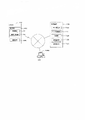
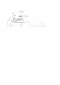
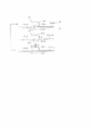
- FIG. 3 is a functional block diagram of an electronic device included in the working machine;
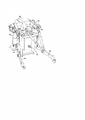
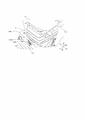
- FIG. 2 is a perspective view of a lifting device included in the working machine;
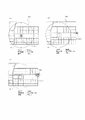
- FIG. 2 is a plan view showing the driver's seat of the vehicle body of the working machine and the area around the driver's seat;
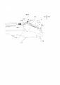
- Fig. 3 is a side view showing an armrest and an operation member in the driver's seat of the vehicle body provided in the working machine;
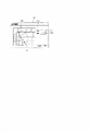
- FIG. 4 is a diagram showing an example of a setting screen displayed on the display of the computer;
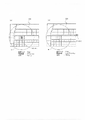
- FIG. It is a figure which shows an example of the area information set by the area setting part of a monitoring apparatus.
- FIG. 2 is a diagram showing an example of an area set corresponding to a work machine and a state where work machines are positioned inside and outside the area. It is a figure which shows a mode that a working machine is mounted in the track
- 4 is a flowchart showing the flow of monitoring start, monitoring cancellation, and notification by monitoring of the work machine 101 by the work machine monitoring system.
- 10 is a flowchart showing the flow of monitoring start, monitoring cancellation, and notification by monitoring of the work machine 101 by the work machine monitoring system in another different form.
- FIG. 2 is a diagram showing an example of an area set corresponding to a work machine and a state where work machines are positioned inside and outside the area.
- FIG. 11 is a perspective view showing a lower portion of a driver's seat and a hydraulic lock lever of the vehicle body provided in the working machine of the second embodiment;
- FIG. 11 is a side view showing an armrest and a shift lever in the driver's seat of the vehicle body provided in the working machine of the third embodiment; It is a figure which shows the operation
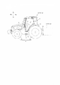
- FIG. 10 is a diagram showing the relationship between area setting and deletion; 1 is an overall view of a working machine; FIG.
- FIG. 1 shows a work machine monitoring system.
- the monitoring system has a monitoring device 100 .
- the monitoring device 100 is a device that monitors the working machine 101 .
- the working machine 101 includes an agricultural machine 101a such as a tractor, a combine, a rice transplanter, and an implement 101b connectable to the agricultural machine 101a (see FIG. 16).
- the monitoring device 100 is a stationary computer such as a server, a mobile computer such as a smart phone, a tablet, or a notebook computer. In this embodiment, the monitoring device 100 is assumed to be a server.
- the work machine 101 may be a construction machine or the like instead of the agricultural machine 101a.
- FIG. 16 is a side view showing a tractor, which is one of the agricultural machines 101a, and an implement 101b that can be attached to the tractor.
- the front side of the driver sitting in the driver's seat 10 of the tractor is defined as the front side
- the rear side of the driver is defined as the rear side
- the left side of the driver is defined as the left side
- the right side of the driver is defined as the right side.
- the horizontal direction which is the direction perpendicular to the front-rear direction of the tractor, will be described as the width direction of the vehicle body.
- the tractor includes a vehicle body 3, a prime mover 4, and a transmission 5.
- the vehicle body 3 has a traveling device 7 and can travel.
- the traveling device 7 is a device having front wheels 7F and rear wheels 7R.
- the front wheels 7F may be of a tire type or a crawler type.
- the rear wheel 7R may be of a tire type or a crawler type.
- the prime mover 4 is a diesel engine, an electric motor, or the like, and is configured by a diesel engine in this embodiment.
- the transmission device 5 can switch the driving force of the traveling device 7 by changing speed, and can switch the traveling device 7 between forward and reverse.
- a driver's seat 10 is provided at the rear portion of the vehicle body 3 .
- a steering wheel 11 is provided in front of the driver's seat 10 .
- a connecting portion configured by a three-point link mechanism or the like is provided.
- the connecting portion is an elevating device 8 that allows the working device (implement) 101b to be detachable and allows the working device (implement) 101b to travel. By connecting the implement 101 b to the lifting device 8 , the implement 101 b can be pulled by the vehicle body 3 .
- the connecting portion may be a traction device that does not move the implement 101b up and down.
- the implement 101b includes a cultivator for tilling, a ridge-raising device for cultivating, a planting device for planting crops, a fertilizer-spraying device for spraying fertilizer, an agricultural chemical-spraying device for spraying agricultural chemicals, a harvesting device for harvesting, and pasture grass.
- a harvesting device for harvesting grass a spreading device for spreading pasture grass, a grass collecting device for collecting pasture grass, and a forming device for forming pasture grass, and the like.
- the transmission 5 includes a main shaft (propulsion shaft) 5a, a main transmission portion 5b, an auxiliary transmission portion 5c, a shuttle portion 5d, a PTO power transmission portion 5e, a front transmission portion 5f, It has
- the propelling shaft 5a is rotatably supported by a housing case (mission case) of the transmission 5, and power from the crankshaft of the prime mover 4 is transmitted to the propelling shaft 5a.
- the main transmission portion 5b has a plurality of gears and a shifter for changing the connection of the gears.
- the main transmission portion 5b changes the rotation input from the propulsion shaft 5a and outputs it (changes speed) by appropriately changing the connection (engagement) of a plurality of gears with a shifter.
- the sub-transmission portion 5c like the main transmission portion 5b, has a plurality of gears and a shifter that changes the connection of the gears.
- the sub-transmission portion 5c appropriately changes the connection (engagement) of a plurality of gears with a shifter, thereby changing and outputting (shifting) the rotation input from the main transmission portion 5b.
- the shuttle portion 5 d has a shuttle shaft 12 and a forward/reverse switching portion 13 . Power output from the auxiliary transmission portion 5c is transmitted to the shuttle shaft 12 via gears or the like.
- the forward/reverse switching unit 13 is composed of, for example, a hydraulic clutch or the like, and switches the rotation direction of the shuttle shaft 12, that is, the forward/reverse of the tractor, by turning on/off the hydraulic clutch.
- the shuttle shaft 12 is connected to the rear wheel differential device 20R.
- the rear wheel differential device 20R rotatably supports a rear axle 21R to which the rear wheels 7R are attached.
- the PTO power transmission section 5e has a PTO propulsion shaft 14 and a PTO clutch 15.
- the PTO propulsion shaft 14 is rotatably supported and can transmit power from the propulsion shaft 5a.
- the PTO propulsion shaft 14 is connected to the PTO shaft 16 via a gear or the like.
- the PTO clutch 15 is composed of, for example, a hydraulic clutch or the like, and the power of the propelling shaft 5a is transmitted to the PTO propelling shaft 14 or not transmitted to the PTO propelling shaft 14 by turning on or off the hydraulic clutch. state.
- the front transmission portion 5f has a first clutch 17 and a second clutch 18.
- the first clutch 17 and the second clutch 18 are capable of transmitting power from the propulsion shaft 5a, for example, the power of the shuttle 12 is transmitted via gears and transmission shafts. Power from the first clutch 17 and the second clutch 18 can be transmitted to the front axle 21 ⁇ /b>F via the front transmission shaft 22 .
- the front transmission shaft 22 is connected to a front wheel differential device 20F, and the front wheel differential device 20F rotatably supports a front axle 21F to which the front wheels 7F are attached.
- the first clutch 17 and the second clutch 18 are composed of hydraulic clutches or the like.
- An oil passage is connected to the first clutch 17, and the oil passage is connected to a first operating valve 25 to which hydraulic oil discharged from a hydraulic pump is supplied.
- the first clutch 17 switches between a connected state and a disconnected state depending on the degree of opening of the first operating valve 25 .
- An oil passage is connected to the second clutch 18 , and the oil passage is connected to a second operating valve 26 .
- the second clutch 18 switches between a connected state and a disconnected state depending on the degree of opening of the second operating valve 26 .
- the first operating valve 25 and the second operating valve 26 are, for example, two-position switching valves with electromagnetic valves, and are switched between a connected state and a disconnected state by energizing or demagnetizing the solenoids of the electromagnetic valves.
- the power of the shuttle shaft 12 is transmitted to the front wheels 7F through the second clutch 18.
- the front wheels 7F and the rear wheels 7R are four-wheel drive (4WD) driven by power, and the rotational speeds of the front wheels 7F and the rear wheels 7R are substantially the same (4WD constant speed state).
- the first clutch 17 is in the engaged state and the second clutch 18 is in the disengaged state
- four-wheel drive is performed and the rotation speed of the front wheels 7F becomes faster than the rotation speed of the rear wheels 7R (4WD acceleration state).
- the first clutch 17 and the second clutch 18 are disengaged, the power of the shuttle shaft 12 is not transmitted to the front wheels 7F, so that the rear wheels 7R are driven by the power, resulting in two-wheel drive (2WD).
- the lifting device 8 has a lift arm 8a, a lower link 8b, a top link 8c, a lift rod 8d and a lift cylinder 8e.
- a front end portion of the lift arm 8a is supported by a rear upper portion of a case (transmission case) that houses the transmission 5 so as to be capable of swinging upward or downward.
- the lift arm 8a swings (moves up and down) by driving the lift cylinder 8e.
- the lift cylinder 8e is composed of a hydraulic cylinder.
- the lift cylinder 8e is connected via a control valve 34 to a hydraulic pump.
- the lift cylinder 8e is switched between a connected state and a disconnected state depending on the degree of opening of the control valve 34. As shown in FIG.
- the control valve 34 is, for example, a two-position switching valve with an electromagnetic valve, and is switched between a connected state and a disconnected state by energizing or demagnetizing the solenoid of the electromagnetic valve.
- the hydraulic pump drives (extends and contracts) the lift cylinder 8e, and when it is in the disconnected state, the driving of the lift cylinder 8e is restricted (locked).
- a front end portion of the lower link 8b is supported by a lower rear portion of the transmission 5 so as to be able to swing upward or downward.
- a front end portion of the top link 8c is supported by the rear portion of the transmission 5 above the lower link 8b so as to be able to swing upward or downward.
- the lift rod 8d connects the lift arm 8a and the lower link 8b.
- the implement 101b is connected to the rear portion of the lower link 8b and the rear portion of the top link 8c.
- the implement 101b swings (moves up and down) upward or downward with the front portion of the lower link 8b as a fulcrum.
- the vertical movement of the implement 101b is also locked.
- the tractor is equipped with a positioning device 40A.
- the positioning device 40A can detect its own position (positioning information including latitude and longitude) by satellite positioning systems (positioning satellites) such as D-GPS, GPS, GLONASS, Hokuto, Galileo, and Michibiki. That is, the positioning device 40A receives satellite signals (position of the positioning satellite, transmission time, correction information, etc.) transmitted from the positioning satellite, and detects the position (for example, latitude and longitude) based on the satellite signal.
- the positioning device 40A has a receiving device 41 and an inertial measurement unit (IMU: Inertial Measurement Unit) 42 .
- IMU Inertial Measurement Unit
- the receiving device 41 is a device that has an antenna or the like and receives satellite signals transmitted from a positioning satellite, and is attached to the vehicle body 3 separately from the inertial measurement device 42 .
- the receiving device 41 is attached to the cabin 9 provided in the vehicle body 3 . Note that the mounting location of the receiving device 41 is not limited to the embodiment.
- the inertial measurement device 42 has an acceleration sensor that detects acceleration, a gyro sensor that detects angular velocity, and the like.
- the inertial measurement device 42 is provided on the vehicle body 3 , for example, below the driver's seat 10 , and can detect the roll angle, pitch angle, yaw angle, and the like of the vehicle body 3 .
- the tractor is equipped with a communication device 45A.
- the communication device 45A is connected to the positioning device 40A, the control device 60, operation members (levers, switches, dials, etc.), and sensors via an in-vehicle communication network N1, and receives electrical signals. ing.
- the communication device 45A can communicate with an external network (outside) different from the in-vehicle communication network N1.
- the communication device 45A is, for example, a communication standard IEEE802.11 series Wi-Fi (Wireless Fidelity, registered trademark), BLE (Bluetooth (registered trademark) Low Energy), LPWA (Low Power, Wide Area), LPWAN ( Wireless communication can be performed by Low-Power Wide-Area Network, etc.
- the communication device 45A can perform wireless communication using, for example, a mobile phone communication network or a data communication network.
- the communication device 45A transmits the vehicle body position (the position of the tractor) detected by the positioning device 40A to the monitoring device 100 . Further, communication device 45A transmits to monitoring device 100 a first signal for monitoring whether work implement 101 is in the area and a second signal for canceling the monitoring.
- the tractor is equipped with a control device 60.
- the control device 60 includes an arithmetic unit (CPU, etc.), a storage unit (memory), etc., and executes predetermined control based on a program stored in the storage unit. More specifically, the control device 60 detects operation signals when operation members (levers, switches, dials, etc.) installed around the driver's seat 10 are operated, and various sensors mounted on the vehicle body 3. It controls the tractor's running system and work system based on signals and the like.
- the control device 60 causes the vehicle body 3 to move forward by switching the forward/reverse switching unit 13 to forward movement. Further, when the shuttle lever 43a is operated to move backward, the control device 60 causes the vehicle body 3 to move backward by switching the forward/reverse switching unit 13 to reverse.
- the control device 60 When the ignition switch 43b (motor operation member) is turned ON, the control device 60 performs predetermined processing to start the motor 4, and when the ignition switch 43b is turned OFF, the driving of the motor 4 is stopped.
- the control device 60 switches the position of the PTO clutch 15 to any of the neutral position, the ON position, and the OFF position, thereby driving the PTO shaft 16. turn on and off.
- the control device 60 changes the rotation speed of the PTO shaft 16 (referred to as the PTO rotation speed) by switching the PTO shift gear built in the transmission 5.
- the control device 60 When the shift changeover switch 43e is switched to the automatic shift, the control device 60 automatically switches either the main transmission section 5b or the sub-transmission section 5c according to the state of the tractor, and changes the shift stage (shift level) of the transmission 5. ) is automatically changed to a predetermined shift stage (shift level).
- the shift switch 43e When the shift switch 43e is switched to manual shifting, the control device 60 automatically switches between the main transmission section 5b and the sub-transmission section 5c according to the shift stage (shift level) set by the shift lever 43f. , changes the gear stage of the transmission 5 .
- the control device 60 changes the speed (velocity) of the vehicle body 3 by changing the number of rotations of the motor 4 (referred to as the number of rotations of the motor) according to the amount of operation of the accelerator lever 43g. do.
- the control device 60 controls the control valve 34 when the hydraulic lever 43h (second indicating member, working device operating member) is operated in the direction of raising (upward side) while the prime mover 4 is being driven. 8e is extended to raise the rear end of the lift arm 8a (the end on the implement 101b side).
- the control device 60 controls the control valve 34 to contract the lift cylinder 8e and move the rear end of the lift arm 8a. (the end on the implement 101b side) is lowered.
- the hydraulic lever 43h is provided with a position sensor 43h4 for detecting the rotational position, so that the operation of the hydraulic lever 43h can be detected.
- the control device 60 disconnects the lift cylinder 8e by the control valve 34, locks the drive of the lift cylinder 8e, and locks the elevation of the implement 101b.
- the control device 60 connects the lift cylinder 8e with the control valve 34 to allow the implement 101b to move up and down.
- the control device 60 transmits the first signal when the ignition switch 43b is being operated to be OFF (while the engine 4 is being stopped) and the monitoring start switch 43j (first instruction member) is operated. It controls the communication device 45A. Further, the control device 60 controls the communication device 45A to transmit the second signal when the position sensor 43h4 detects the operation of the hydraulic lever 43h while the prime mover 4 is stopped.
- an armrest 50 is provided on the right side of the driver's seat 10 in plan view.
- the armrest 50 is arranged with its longitudinal direction facing the front-rear direction and its short side facing the width direction of the vehicle body.
- a side console 51 is provided on the right side of the armrest 50 in the width direction of the vehicle body.
- the side console 51 has a front end positioned forward of the driver's seat 10 and a rear end positioned rearward of the driver's seat 10 .
- a front console 52 is provided in front of the driver's seat 10 in plan view. The rear end of the front console 52 is located forward of the driver's seat 10 .
- the operation members described above are provided near the driver's seat 10 such as an armrest 50, a side console 51, and a front console 52 so as to be operable by the driver. The arrangement of main operation members will be described below.
- a front portion 50a is provided on the front side of the armrest 50 in the longitudinal direction.
- the front portion 50a is arranged in front of the backrest portion 10a of the driver's seat 10 in the longitudinal direction and overlaps the seat portion 10b.
- a rotary dial type accelerator lever 43g is provided at the forefront of the front portion 50a.
- a shift lever 43f is provided behind the accelerator lever 43g in the front portion 50a.
- the shift lever 43 f is a swing operation type lever that has a grip portion and a swing shaft and protrudes upward from the armrest 50 .
- a hydraulic lever 43h is provided behind the shift lever 43f in the front portion 50a.
- the hydraulic lever 43h has a rotating body 43h1, a knob portion 43h2, and a lock portion 43h3.
- the rotating body 43h1 protrudes upward in an arcuate shape from the upper surface of the armrest 50 in a side view.
- the knob portion 43h2 protrudes from the upper surface of the rotating body 43h1.
- the rotating body 43h1 is attached to the armrest 50 so as to be rotatable around a sideways (horizontal) support shaft.
- a position sensor 43h4 is provided inside the armrest 50 to detect the rotation of the rotating body 43h1.
- the rotating body 43h1 rotates around the spindle.
- the lift cylinder 8e of the lifting device 8 is shortened and the implement 101b is lowered.
- the lift cylinder 8e of the lifting device 8 is extended to lift the implement 101b.
- the lock portion 43h3 is arranged on the vehicle body inner side (driver's seat 10 side) of the knob portion 43h2, and can swing forward, backward, or upward with respect to the shaft portion.
- the lock portion 43h3 is positioned forward or rearward with respect to the shaft portion, the position of the knob portion 43h2 is fixed, and the movement operation of the knob portion 43h2 is blocked.
- FIG. 5 shows a state in which the lock portion 43h3 is positioned forward (tilted forward) with respect to the shaft portion.
- the phantom line (chain line) in FIG. 5 when the lock portion 43h3 is directed upward (upright) with respect to the shaft portion, the position of the knob portion 43h2 is unlocked, and the knob portion A move operation of 43h2 is allowed.
- the rotating body 43h1 rotates due to the moving operation of the knob 43h2 while the motor 4 is stopped, the rotation is detected by the position sensor 43h4, and a signal is sent to the in-vehicle communication network N1. .
- the control device 60 receives the signal and recognizes that the hydraulic lever 43h has been operated.
- a central portion 51a is provided at substantially the central portion of the side console 51 in the longitudinal direction.
- the central portion 51 a is located on the rear side of the front portion 50 a of the armrest 50 .
- a PTO switch 43c is provided in the central portion 51a.
- the PTO switch 43c can be switched between three positions, a neutral position, an ON position, and an OFF position. By operating the PTO switch 43c to the neutral position, the ON position and the OFF position, the position of the PTO clutch 15 is switched to the neutral position, the ON position and the OFF position, respectively.
- a column cover 52a is provided at the substantially central portion of the front console 52 in the width direction of the vehicle body.
- the steering wheel 11 is supported on the upper part of the column cover 52a and provided to face the front of the driver's seat 10.
- An ignition switch 43b and a monitoring start switch 43j are provided on the rear side of the front console 52 and on the right and left sides of the column cover 52a, respectively.
- the ignition switch 43b is a push button that is operated by pressing. When the ignition switch 43b is turned on while the motor 4 is stopped, the motor 4 is started. When the ignition switch 43b is turned off while the prime mover 4 is being driven, the prime mover 4 is stopped. A signal indicating that the ignition switch 43b is turned OFF is sent to the in-vehicle communication network N1. Upon receiving the signal, the control device 60 recognizes that the ignition switch 43b is being pushed to the OFF position.
- the monitoring start switch 43j is a push button operated by pressing. A signal indicating that the monitoring start switch 43j has been pressed is sent to the in-vehicle communication network N1. The control device 60 receives the signal and recognizes that the monitoring start switch 43j has been pressed.
- a hydraulic lock lever 43i is provided below the steering wheel 11 and in front of the seat portion 10b of the driver's seat 10. As shown in FIG.
- the hydraulic lock lever 43i is a swing operation type lever that has a grip portion and a swing shaft and protrudes forward from the seat portion 10b.
- the monitoring device (server) 100 includes an area setting section 110A and an area storage device 111 .
- the area setting unit 110A is configured by an electrical/electronic circuit provided in the monitoring device 100, a program stored in the monitoring device 100, and the like.
- the area storage device 111 is composed of a non-volatile memory or the like.
- Area setting unit 110A sets area 150 of work machine 101 .
- a stationary computer 105 different from the monitoring device 100 is connected to the monitoring device 100, and when a predetermined operation is performed on the stationary computer 105, a screen shown in FIG.
- the setting screen M1 is displayed on the display unit 105A such as a monitor of the stationary computer 105.
- the computer 105 is installed, but may be a portable computer such as a smart phone, tablet, or laptop.
- the setting screen M1 includes a work machine input portion 121 for inputting the work machine 101, a map display portion 122 for displaying a map, a pointer 123 for selecting an arbitrary point on the map, and a distance input portion 124 for inputting a distance. contains.
- Work machine input unit 121 can input identification information for identifying work machine 101 .
- identification information various information such as the serial number, name, model number, type, and manufacturing number of work machine 101 can be input.
- the map display portion 122 is a portion that displays a map including roads, farm roads, working places such as agricultural fields, buildings, and the like. It is displayed on the map display section 122 .
- the map may be, for example, a map obtained from a map providing company that provides map data, or may be a map created by a stationary computer 105 or the like, but is not limited thereto.
- the area 150 can be set for the work machine 101 by inputting the work machine identification information, the center O1 and the distance L1 on the setting screen M1.
- the pointer 123 selects the center of the area 150, but the pointer 123 may be configured to select a plurality of positions (points) on the map.
- area setting section 110A sets an area surrounded by a plurality of positions (points) as area 150 .
- the area information set by the area setting unit 110A (working machine identification information, information indicating the area 150) is stored in the area storage device 111.
- the monitoring device 100 includes a notification unit 112A.
- 112 A of notification parts are comprised by the program etc. which were stored in the electrical/electronic circuit provided in the monitoring apparatus 100, and the work assistance apparatus 100.
- FIG. Notification unit 112A notifies work machine 101 based on whether or not work machine 101 is located within area 150 defined for work machine 101 . Assume that an area 150 is set for the tractor T as shown in FIG. 8(a). In this area 150, the center O1 and the distance L1 are set so that the garage G is located in the center.
- the notification unit 112A determines whether the vehicle body position is within the area 150 or not.
- the notification unit 112A when the work implement 101 is being monitored, the notification unit 112A does not notify when the vehicle body position is within the area 150 (for example, the position of the garage G).
- the tractor T when the work implement 101 is being monitored, for example, the tractor T may be moved out of the garage G and the position of the tractor T may deviate from the area 150 .
- the notification unit 112A determines that the vehicle body position is outside the area 150, and notifies the installed computer 105 or the like that "the tractor T is out of the area 150." In other words, the notification unit 112A monitors the work machine 101 by notifying the installation type computer 105 or the like of whether the work machine 101 is in the area 150 defined for the work machine 101. there is If work machine 101 is out of area 150 for a long period of time, it can be determined that work machine 101 may have been stolen. can be prevented.
- the tractor T (working machine 101) is driven to move from the garage G and mounted on the vehicle-mounted platform 102a of the stopped vehicle-mountable truck 102. .
- the motor 4 of the working machine 101 is stopped and the truck 102 moves toward the destination.
- the truck 102 deviates from the area 150 to the outside, the work implement 101 is positioned outside the area 150 together with the truck 102 .
- the above notification will be executed even if work machine 101 is not stolen. In this way, even when working machine 101 is intentionally positioned outside area 150 instead of being stolen, it is likely to be erroneously determined to be theft. Therefore, there is a high possibility that the user will be confused with the occurrence of theft, and if the user becomes accustomed to the above notification, there is a high possibility that the actual theft will be overlooked and security will be lowered.
- the monitoring device 100 includes a monitoring starting unit 112B and a monitoring canceling unit 112C (see FIG. 1).
- the monitoring flag is switched ON and OFF by the monitoring start unit 112B and the monitoring cancellation unit 112C.
- the monitoring flag is ON, whether or not work implement 101 is within area 150 is monitored, and when the monitor flag is OFF, whether or not work implement 101 is within area 150 is not monitored. That is, when the monitoring flag is changed from OFF to ON, monitoring of the work implement 101 is started. On the other hand, when the monitoring flag is changed from ON to OFF, the monitoring of work implement 101 is cancelled.
- the monitoring start unit 112B and the monitoring cancellation unit 112C are composed of electrical and electronic circuits provided in the monitoring device 100, programs stored in the work support device 100, and the like.
- the monitoring start unit 112B turns on the monitoring flag when the first signal transmitted from the communication device 45A is received while the monitoring flag is in the OFF state.
- the monitoring canceling unit 112C turns off the monitoring flag when the second signal transmitted from the communication device 45A is received while the monitoring flag is in the ON state.
- the monitoring flag is turned ON, and monitoring is started so that notification by the notification unit 112A is permitted.
- the monitoring flag is turned OFF, and monitoring is canceled so that notification by the notification unit 112A is restricted.
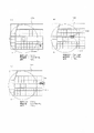
- FIG. 10A is a flowchart showing the flow of monitoring start, monitoring cancellation, and notification by monitoring of the work machine 101 , and also shows the operation flow of the work machine 101 and the monitoring device 100 .
- area 150 is set in advance for work machine 101 by area setting unit 110A.
- the area 150 includes the garage G of the working machine 101 at its center. It is also assumed that the monitor flag is in the OFF state.
- the working machine 101 that has finished working in a field outside the area 150 moves by itself to the garage G inside the area 150 (S1).
- the driver presses the ignition switch 43b to OFF while sitting on the driver's seat 10 .
- the driver presses the monitoring start switch 43j while pressing the ignition switch 43b.
- the driver leaves the driver's seat 10 and stores the working machine 101 in the garage G (S2).
- the first signal is transmitted from the communication device 45A to the monitoring device 100 and received by the monitoring device 100 (S3).
- the monitoring start unit 112B determines whether or not the monitoring flag is in the OFF state and the first signal has been received.
- the monitoring start unit 112B turns the monitoring flag from OFF to ON, and monitoring is started so that the notification by the notification unit 112A is permitted (S5) (see FIG. 8A). It should be noted that, if the determination in S4 is "No", the monitoring flag is kept OFF and the notification by the notification unit 112A is restricted.
- the vehicle body position detected by the positioning device 40A is transmitted from the communication device 45A to the monitoring device 100 and received by the monitoring device 100 (S6).
- the notification unit 112A determines whether the received vehicle body position is outside the area 150 or not. If the vehicle body position is outside the area 150, the determination is "Yes” (S7) (see FIG. 8(b)).
- the notification unit 112A notifies the stationary computer 105 that "the tractor T is out of the area 150" (S8). As shown in FIG. 8(a), when the vehicle is normally stored in the garage G, the determination in S7 is "No" and the above notification is not made.
- the driver of the work machine 101 mounted on the vehicle-mounted stand 102a while seated on the driver's seat 10, pushes the ignition switch 43b to OFF to stop the prime mover 4, and rotates the rotating body 43h1 of the hydraulic lever 43h. do. Then, the driver leaves the working machine 101 on the truck 102 and leaves the driver's seat 10 (S13).
- the second signal is transmitted from the communication device 45A to the monitoring device 100 and received by the monitoring device 100 (S14).
- the monitoring canceling unit 112C determines whether or not the monitoring flag is ON and the second signal is received. At this time, the monitoring flag is ON and the second signal has been received, so the determination is "Yes" (S15).
- the monitoring cancellation unit 112C turns the monitoring flag from ON to OFF, and cancels the monitoring so that the notification by the notification unit 112A is restricted (S16).
- the truck 102 loaded with the working machine 101 moves from inside the area 150 to outside.
- the monitoring of the work machine 101 has been canceled by the above S16, and the notification from the notification unit 112A is not executed. It should be noted that if the determination in S15 is "No", the monitoring flag is kept ON and the notification by the notification unit 112A is permitted.
- the second signal is transmitted from the communication device 45A to the monitoring device 100 when the monitoring flag is ON and the operation of the hydraulic lever 43h is detected while the prime mover 4 is stopped. .
- the monitoring flag of the monitoring device 100 is turned off, and the monitoring of the working machine 101 is canceled.
- the second embodiment differs from the first embodiment only in that the operating member used for transmitting the second signal is the hydraulic lock lever 43i (second pointing member, lock operating member). Differences of the second embodiment from the first embodiment will be described below.
- the seat portion 10b of the driver's seat 10 is supported from below by a support portion 10b1.
- the support portion 10b1 is configured such that the front-rear position of the seat portion 10b, the tilt position of the backrest portion 10a, and the like can be adjusted by a lever.
- a case 53 a is interposed between the lower end of the support portion 10 b 1 and the floor 53 .
- the case 53a is a substantially rectangular parallelepiped housing, and defines a front surface 53a1 facing the tip side of the seat portion 10b.
- the front surface 53 a 1 stands substantially perpendicular to the floor 53 .
- a hydraulic lock lever 43i is provided at substantially the center of the front surface 53a1 in the width direction of the vehicle body. The hydraulic lock lever 43i is located below the steering wheel 11 and in front of the seat portion 10b of the driver's seat 10. As shown in FIG.
- the hydraulic lock lever 43i has a swing shaft 43i1 and a grip portion 43i2.
- the swing shaft 43i1 protrudes forward from the front surface 53a1 of the case 53a.
- the grip portion 43i2 protrudes upward from the front end of the swing shaft 43i1.
- the rear portion of the swing shaft 43i1 is attached so as to be swingable around a vertically oriented (vertical) support shaft arranged inside the case 53a. That is, the hydraulic lock lever 43i is a swing operation type lever that protrudes forward from the seat portion 10b, and is swingable in the width direction of the vehicle body.
- a position sensor 43i3 for detecting the swing of the swing shaft 43i1 is provided inside the case 53a.
- the rocking shaft 43i1 rocks around the support shaft.
- the grip portion 43i2 is moved to the right, the drive of the lift cylinder 8e is locked, and the vertical movement of the implement 101b is also locked. That is, the hydraulic lock lever 43i is turned ON.
- the grip portion 43i2 is moved leftward, the drive of the lift cylinder 8e is permitted, and the implement 101b is also permitted to move up and down. That is, the hydraulic lock lever 43i is turned off.
- the driver grasps the grip portion 43i2 and moves it to the right or left, so that the swing of the swing shaft 43i1 is detected by the position sensor 43i3. , and a signal is sent out to the in-vehicle communication network N1.
- the control device 60 receives the signal and recognizes that the hydraulic lock lever 43i has been operated.
- the control device 60 of the second embodiment controls the communication device 45A to transmit the second signal when the position sensor 43i3 detects the operation of the hydraulic lock lever 43i while the prime mover 4 is stopped.
- the second signal is transmitted from the communication device 45A to the monitoring device 100 when the monitoring flag is ON and the operation of the hydraulic lock lever 43i is detected while the prime mover 4 is stopped. be.
- the monitoring flag of the monitoring device 100 is turned off, and the monitoring of the working machine 101 is canceled.
- the third embodiment differs from the first and second embodiments only in that the operating member used for transmitting the second signal is a shift lever 43f (second indicating member, shift operating member). The differences of the third embodiment from the first and second embodiments will be described below.
- the shift lever 43f has a swing shaft 43f1 and a grip portion 43f2.
- the swing shaft 43f1 protrudes upward from the upper surface of the armrest 50 in a side view.
- the grip portion 43f2 is provided at the upper end of the swing shaft 43f1.
- the swing shaft 43f1 is attached so as to be swingable around a sideways (horizontal) support shaft arranged inside the armrest 50 .
- a position sensor 43f3 for detecting the swing of the swing shaft 43f1 is provided inside the armrest 50.
- the driver who is seated in the driver's seat 10, grips the grip portion 43f2 and moves it forward or backward, whereby the rocking motion of the rocking shaft 43f1 is detected by the position sensor 43f3. Then, the signal is sent out to the in-vehicle communication network N1.
- the control device 60 receives the signal and recognizes that the shift lever 43f has been operated.
- the control device 60 of the third embodiment controls the communication device 45A to transmit the second signal when the position sensor 43f3 detects the operation of the shift lever 43f while the prime mover 4 is stopped.
- the second signal is transmitted from the communication device 45A to the monitoring device 100 when the monitoring flag is ON and the operation of the shift lever 43f is detected while the prime mover 4 is stopped. .
- the monitoring flag of the monitoring device 100 is turned off, and the monitoring of the working machine 101 is canceled.
- the fourth embodiment differs from the first, second, and third embodiments only in that the operating member used for transmitting the second signal is the PTO switch 43c (second pointing member, PTO operating member). Differences of the fourth embodiment from the first, second, and third embodiments will be described below.
- the PTO switch 43c provided in the central portion 51a of the side console 51 has a rotating portion 43c1 and a supporting portion 43c2.
- the PTO switch 43c is a switch that can be pushed and rotated.
- the rotating portion 43c1 has a circular shape in plan view, and is rotatably supported by the supporting portion 43c2.
- the support portion 43c2 protrudes from the inside of the side console 51 to the outside, and one end of the support portion 43c2 is connected to the rotating portion 43c1 outside.
- the PTO switch 43c When the rotating part 43c1 is in the upper position away from the upper surface of the side console 51, the PTO switch 43c is in the neutral position. Accordingly, the PTO clutch 15 is brought into the neutral state. When the rotating portion 43c1 is pushed in from the neutral position and reaches the lower position close to the upper surface of the side console 51, the PTO switch 43c is turned off. Accordingly, the PTO clutch 15 is switched to the OFF state. When the rotating part 43c1 is rotated from the OFF position to a predetermined position, the PTO switch 43c is turned to the ON position. Accordingly, the PTO clutch 15 is switched to the ON state. When the rotating part 43c1 is released from the ON position, the rotating part 43c1 automatically returns to the upper position via the lower position. That is, the PTO switch 43c is a momentary switch that automatically returns from the OFF position to the neutral position.
- the support part 43c2 is displaced integrally with the rotating part 43c1 between the upper position and the lower position.
- a position sensor 43c3 for detecting displacement of the support portion 43c2 is provided inside the side console 51.
- the position sensor 43c3 detects the displacement of the supporting portion 43c2 by holding and pushing the rotating portion 43c1. A signal is sent towards N1.
- the control device 60 receives the signal and recognizes that the PTO switch 43c has been operated.
- the control device 60 of the fourth embodiment controls the communication device 45A to transmit the second signal when the position sensor 43c3 detects the operation of the PTO switch 43c while the prime mover 4 is stopped.
- ⁇ Modification 1 Transmission operation of the first signal>
- the first signal in each of the above-described embodiments is transmitted when the monitoring flag is OFF, the ignition switch 43b is being turned OFF (during operation to stop the prime mover 4), and the monitoring start switch 43j is operated. It was like Alternatively, for example, the monitoring flag is OFF, the engine 4 is stopped (the engine 4 is stopped after the ignition switch 43b has been turned off), and the monitoring start switch 43j (second 1 pointing member) is operated, the control device 60 may control the communication device 45A to transmit the first signal.
- the second signal in each of the above embodiments is that the monitoring flag is ON and the motor 4 is stopped, the hydraulic lever 43h (first embodiment), the hydraulic lock lever 43i (second embodiment), the shift lever 43f ( (third embodiment) or when the PTO switch 43c (fourth embodiment) is operated.
- the control device 60 may control the communication device 45A to transmit the second signal.
- a plurality of corresponding position sensors are provided in order to detect the operation of each operating member.
- a monitoring system for work machine 101 includes monitoring device 100 that monitors whether work machine 101 is in area 150 when a first signal is received, and cancels the monitoring when a second signal is received.
- Work machine 101 includes at least a communication device 45A that transmits a first signal and a second signal to monitoring device 100, and a first instruction member that instructs communication device 45A to transmit the first signal when operated. and a second instruction member that is operated when the monitoring device 100 is monitoring the working machine 101 to instruct the communication device 45A to transmit the second signal.
- the first and second signals are transmitted from work machine 101 by operating the first and second pointing members provided in work machine 101 . Therefore, the monitoring of the work machine 101 can be arbitrarily started and/or canceled on the work machine 101 side. For example, even if work machine 101 is intentionally positioned outside area 150 instead of being stolen, since monitoring can be canceled in advance, erroneous determination of theft can be suppressed. Moreover, even after the monitoring is canceled, the monitoring can be started as necessary.
- the working machine 101 further includes a prime mover 4 .
- the communication device 45A outputs the first signal when the prime mover 4 is stopped and the monitoring start switch 43j (first indicating member) is operated. According to this, it is possible to appropriately and easily start monitoring the working machine 101 in preparation for storage or the like when the demand for monitoring is large.
- the work machine 101 further includes a motor 4 and an ignition switch 43b (motor operating member) for starting or stopping the motor 4 .
- the communication device 45A outputs the first signal when the monitoring start switch 43j is operated while the ignition switch 43b is being operated to stop. According to this, it is possible to appropriately and easily start monitoring the working machine 101 in preparation for storage or the like when the demand for monitoring is large.
- the work machine 101 further includes an implement 101b that is driven by the prime mover 4, and a hydraulic lever 43h (work implement operation member) that operates the implement 101b while the prime mover 4 is driving.
- the hydraulic lever 43h serves as a second instruction member and instructs the communication device 45A to transmit a second signal. According to this, it is possible to utilize working device operation members that are generally provided in agricultural machinery, etc., and there is no need to newly install an operation member exclusively for transmitting the second signal, and it is possible to operate the transmission of the second signal while sitting in the driver's seat. becomes. Therefore, the monitoring of the working machine 101 can be appropriately and easily released.
- the work machine 101 further includes an implement 101b driven by the prime mover 4, a hydraulic lever 43h that operates the implement 101b while the prime mover 4 is driving, and the implement 101b that is operated by operating the hydraulic lever 43h. and a hydraulic lock lever 43i (lock operation member).
- the hydraulic lock lever 43i serves as a second instruction member and instructs the communication device 45A to transmit a second signal when operated while the prime mover 4 is stopped. According to this, it is possible to utilize a lock operation member that is generally provided in agricultural machinery, etc., and there is no need to install a new operation member exclusively for transmitting the second signal, and it is possible to operate the transmission of the second signal while sitting in the driver's seat. Become. Therefore, the monitoring of the working machine 101 can be appropriately and easily released.
- the lock operation member is often installed at a location independent from the installation locations of other operation members (for example, the lower part of the seat portion 10b, etc.). Therefore, the user can easily specify the operation location, and can reliably perform the operation of transmitting the second signal.
- the work machine 101 further includes a travel device 7 driven by the prime mover 4 and a shift lever 43f (shift operation member) for shifting the travel device 7.
- shift lever 43f shift operation member
- a gear shift operation member generally provided in agricultural machinery and the like, eliminate the need to install a new operation member exclusively for transmitting the second signal, and operate the transmission of the second signal while seated in the driver's seat. Become. Therefore, the monitoring of the working machine 101 can be appropriately and easily released.
- the work machine 101 further includes an implement 101b and a PTO switch 43c (PTO operation member) that changes power to the PTO shaft 16 that transmits power to the implement 101b.
- the PTO switch 43c serves as a second instruction member and instructs the communication device 45A to transmit a second signal when operated while the motor 4 is stopped. According to this, it is possible to utilize the PTO operation member that is generally provided in agricultural machinery and the like, eliminate the need to install a new operation member exclusively for transmitting the second signal, and operate the second signal transmission while sitting in the driver's seat. Become. Therefore, the monitoring of the working machine 101 can be appropriately and easily released.
- the second signal is transmitted from the working machine 101 to the monitoring device 100, and when the monitoring device 100 receives the second signal, monitoring is canceled ( (No notification is made even if the working machine 101 leaves the area 150), but instead of this, when the monitoring device 100 receives the second signal, the setting of the area 150 is canceled, that is, the area 150 is deleted. may be performed. In other words, canceling the monitoring includes not giving notification even if the work implement 101 leaves the area 150 under the conditions where the area 150 is set, or deleting the setting of the area 150 itself.
- the area 150 is deleted as the monitoring of the working machine 101 is cancelled.
- the monitoring device 100 instead of switching the monitoring flag ON/OFF, the area 150 is set and deleted by the area setting section 110A in response to the first signal and the second signal. Different from the embodiment.
- FIG. 10B is a flowchart showing the flow of monitoring start, monitoring cancellation, and notification by monitoring of the work machine 101 by a work machine monitoring system different from that of FIG. 10A.
- FIG. 15 is a diagram showing the relationship between setting and deletion of the area 150. As shown in FIG. In FIG. 10B, the same steps as those shown in FIG. 10A are denoted by the same reference numerals, and description thereof is omitted. It is also assumed that the area 150 is not set at the start.
- the area setting unit 110A determines whether the area 150 is not set and the first signal is received. In S18 corresponding to S5 (see FIG. 10A), if the determination in S17 is "Yes", the area setting unit 110A sets the area 150, and the monitoring of the working machine 101 is started. That is, notification by the notification unit 112A is permitted. It should be noted that if the determination in S17 is "No", the area 150 remains unset, and the monitoring of the work implement 101 is not started.
- the notification unit 112A When the area 150 is set by the area setting unit 110A, as shown in FIG. 15(a), when the tractor T is located within the area 150, the notification unit 112A does not notify. As shown in FIG. 15(b), when the tractor T moves out of the area 150, a notification is made by the notification unit 112A.
- the area setting unit 110A determines whether the area 150 is set and the second signal is received. In S20 corresponding to S16 (see FIG. 10A), if the determination in S19 is "Yes", the area setting unit 110A deletes the area 150 and the monitoring of the working machine 101 is cancelled. That is, notification by the notification unit 112A is restricted. It should be noted that if the determination in S19 is "No", the area 150 remains set and the monitoring of the working machine 101 is not canceled.
- the area 150 can be set again from the setting screen M1 of the computer 105 by remotely moving from the work machine 101. Alternatively, the area 150 may be set again by transmitting the first signal from the work implement 101 side.
Landscapes
- Engineering & Computer Science (AREA)
- Life Sciences & Earth Sciences (AREA)
- General Engineering & Computer Science (AREA)
- Civil Engineering (AREA)
- Structural Engineering (AREA)
- Mining & Mineral Resources (AREA)
- Mechanical Engineering (AREA)
- Soil Sciences (AREA)
- Environmental Sciences (AREA)
- Computer Networks & Wireless Communication (AREA)
- Alarm Systems (AREA)
- Selective Calling Equipment (AREA)
- Lifting Devices For Agricultural Implements (AREA)
- Guiding Agricultural Machines (AREA)
Abstract
作業機101の監視システムは、第1信号を受信した場合に作業機101がエリア内にいるか否かを監視し、第2信号を受信した場合に監視を解除する監視装置100を備える。作業機101は、少なくとも、第1信号及び第2信号を、監視装置100に送信する通信装置45Aと、操作されることで第1信号を送信するよう通信装置45Aに指示する第1指示部材と、監視装置100が作業機101を監視している場合に操作されることで、第2信号を送信するよう通信装置45Aに指示する第2指示部材と、を備えている。
Description
本発明は、例えば、農業機械、建設機械等を含む作業機の監視システムに関する。
従来、農業機械等の作業機を監視するためのシステムとして、特許文献1の監視システムが知られている。特許文献1の監視システムは、第1通信装置と、第2通信装置と、を備えている。第1通信装置は、作業機に設けられるものであり、ビーコンを出力可能となっている。第2通信装置は、作業機の保管場所等に設置されるものであり、第1通信装置からのビーコンを受信可能となっている。第2通信装置は、ビーコンを受信している状態から受信できなくなった場合に、外部に警報を出力する監視部を有している。
特許文献1のシステムでは、監視中において、例えば、作業機が保管場所から移動して、監視部がビーコン受信できなくなったことを受け、外部に警報が送信される。これにより、作業機の盗難防止が期待できる。しかしながら、盗難ではなく意図的に、原動機を始動させずに作業機を保管場所から移動させる場合もある。この場合、作業機が監視されていると、盗難されてない場合であっても警告が送信されることがあり、誤って盗難と判断され易い。従って、盗難発生と混同させてしまう可能性が高く、また、ユーザが警告に慣れてしまうと、実際の盗難を看過する恐れがあり、セキュリティが低下する可能性も高い。
そこで、本発明は上記問題点に鑑み、作業機の監視を、作業機側にて任意に開始、及び/又は、解除することができる作業機の監視システムを提供することを目的とする。
この技術的課題を解決するための本発明の技術的手段は、以下に示す点を特徴とする。作業機の監視システムは、第1信号を受信した場合に作業機がエリア内にいるか否かを監視し、第2信号を受信した場合に前記監視を解除する監視装置を備え、前記作業機は、少なくとも、前記第1信号及び前記第2信号を、前記監視装置に送信する通信装置と、操作されることで、前記第1信号を送信するよう前記通信装置に指示する第1指示部材と、前記監視装置が前記作業機を監視している場合に、操作されることで、前記第2信号を送信するよう前記通信装置に指示する第2指示部材と、を備えている。
前記作業機は、更に、原動機を備え、前記通信装置は、前記原動機が停止中で且つ、前記第1指示部材が操作された場合に前記第1信号を出力する。
前記作業機は、更に、原動機と、前記原動機の始動又は停止の操作を行う原動機操作部材と、を備え、前記通信装置は、前記原動機操作部材による停止の操作中に、前記第1指示部材が操作された場合に前記第1信号を出力する。
前記作業機は、更に、前記原動機により駆動する作業装置と、前記原動機が駆動中に前記作業装置を操作する作業装置操作部材と、を備え、前記作業装置操作部材は、前記原動機が停止中に操作した場合は、前記第2指示部材として、前記第2信号を送信するよう前記通信装置に指示する。
前記作業機は、更に、前記原動機により駆動する作業装置と、前記原動機が駆動中に前記作業装置を操作する作業装置操作部材と、前記作業装置操作部材の操作によって前記作業装置が作動しないように操作するロック操作部材と、を備え、前記ロック操作部材は、前記原動機が停止中に操作した場合は、前記第2指示部材として、前記第2信号を送信するよう前記通信装置に指示する。
前記作業機は、更に、前記原動機により駆動する走行装置と、前記走行装置の変速を行う変速操作部材と、を備え、前記変速操作部材は、前記原動機が停止中に操作した場合は、前記第2指示部材として、前記第2信号を送信するよう前記通信装置に指示する。
前記作業機は、更に、作業装置と、前記作業装置に動力を伝達するPTO軸への動力を変更するPTO操作部材と、を備え、前記PTO操作部材は、前記原動機が停止中に操作した場合は、前記第2指示部材として、前記第2信号を送信するよう前記通信装置に指示する。
本発明によれば、作業機の監視を、作業機側にて任意に開始、及び/又は、解除することができる。
以下、本発明の実施の形態を図面に基づいて説明する。
[第1実施形態]
図1は、作業機の監視システムを示している。監視システムは、監視装置100を備えている。監視装置100は、作業機101の監視を行う装置である。作業機101は、トラクタ、コンバイン、田植機等の農業機械101aと、農業機械101aに連結可能なインプルメント101bと、を含んでいる(図16参照)。監視装置100は、サーバ等の設置型のコンピュータ、スマートフォン、タブレット、ノートパソコン等の携帯型のコンピュータ等である。この実施形態では、監視装置100は、サーバであるとして説明を進める。なお、当該作業機101は、農業機械101aに代えて、建設機械等であってもよい。
図1は、作業機の監視システムを示している。監視システムは、監視装置100を備えている。監視装置100は、作業機101の監視を行う装置である。作業機101は、トラクタ、コンバイン、田植機等の農業機械101aと、農業機械101aに連結可能なインプルメント101bと、を含んでいる(図16参照)。監視装置100は、サーバ等の設置型のコンピュータ、スマートフォン、タブレット、ノートパソコン等の携帯型のコンピュータ等である。この実施形態では、監視装置100は、サーバであるとして説明を進める。なお、当該作業機101は、農業機械101aに代えて、建設機械等であってもよい。
<作業機>
図16は、農業機械101aの1つであるトラクタと、トラクタに装着可能なインプルメント101bとを示す側面図である。以下、トラクタの運転席10に着座した運転者の前側を前方、運転者の後側を後方、運転者の左側を左方、運転者の右側を右方として説明する。また、トラクタの前後方向に直交する方向である水平方向を車体幅方向として説明する。
図16は、農業機械101aの1つであるトラクタと、トラクタに装着可能なインプルメント101bとを示す側面図である。以下、トラクタの運転席10に着座した運転者の前側を前方、運転者の後側を後方、運転者の左側を左方、運転者の右側を右方として説明する。また、トラクタの前後方向に直交する方向である水平方向を車体幅方向として説明する。
図16に示すように、トラクタは、車体3と、原動機4と、変速装置5とを備えている。車体3は、走行装置7を有していて走行可能である。走行装置7は、前輪7F及び後輪7Rを有する装置である。前輪7Fは、タイヤ型であってもクローラ型であってもよい。また、後輪7Rも、タイヤ型であってもクローラ型であってもよい。原動機4は、ディーゼルエンジン、電動モータ等であって、この実施形態ではディーゼルエンジンで構成されている。変速装置5は、変速によって走行装置7の推進力を切換可能であると共に、走行装置7の前進、後進の切換が可能である。車体3の後部には、運転席10が設けられている。運転席10の前方には、ステアリングホイール11が設けられている。
また、車体3の後部には、3点リンク機構等で構成された連結部が設けられている。連結部は、作業装置(インプルメント)101bを着脱可能且つ、作業装置(インプルメント)101bを走行可能とする昇降装置8である。インプルメント101bを昇降装置8に連結することによって、車体3によってインプルメント101bを牽引することができる。なお、連結部は、インプルメント101bを昇降しない牽引装置であってもよい。インプルメント101bは、耕転する耕転装置、畝立を行う畝立装置、作物を植え付ける植付装置、肥料を散布する肥料散布装置、農薬を散布する農薬散布装置、収穫を行う収穫装置、牧草等の刈取を行う刈取装置、牧草等の拡散を行う拡散装置、牧草等の集草を行う集草装置、牧草等の成形を行う成形装置等である。
図2に示すように、変速装置5は、主軸(推進軸)5aと、主変速部5bと、副変速部5cと、シャトル部5dと、PTO動力伝達部5eと、前変速部5fと、を備えている。推進軸5aは、変速装置5のハウジングケース(ミッションケース)に回転自在に支持され、当該推進軸5aには、原動機4のクランク軸からの動力が伝達される。主変速部5bは、複数のギア及び当該ギアの接続を変更するシフタを有している。主変速部5bは、複数のギアの接続(噛合)をシフタで適宜変更することによって、推進軸5aから入力された回転を変更して出力する(変速する)。
副変速部5cは、主変速部5bと同様に、複数のギア及び当該ギアの接続を変更するシフタを有している。副変速部5cは、複数のギアの接続(噛合)をシフタで適宜変更することによって、主変速部5bから入力された回転を変更して出力する(変速する)。シャトル部5dは、シャトル軸12と、前後進切換部13とを有している。シャトル軸12には、副変速部5cから出力された動力がギア等を介して伝達される。前後進切換部13は、例えば、油圧クラッチ等で構成され、油圧クラッチの入切によってシャトル軸12の回転方向、即ち、トラクタの前進及び後進を切り換える。シャトル軸12は、後輪デフ装置20Rに接続されている。後輪デフ装置20Rは、後輪7Rが取り付けられた後車軸21Rを回転自在に支持している。
PTO動力伝達部5eは、PTO推進軸14と、PTOクラッチ15とを有している。PTO推進軸14は、回転自在に支持され、推進軸5aからの動力が伝達可能である。PTO推進軸14は、ギア等を介してPTO軸16に接続されている。PTOクラッチ15は、例えば、油圧クラッチ等で構成され、油圧クラッチの入切によって、推進軸5aの動力をPTO推進軸14に伝達する状態と、推進軸5aの動力をPTO推進軸14に伝達しない状態とに切り換わる。
前変速部5fは、第1クラッチ17と、第2クラッチ18とを有している。第1クラッチ17及び第2クラッチ18は、推進軸5aからの動力が伝達可能であって、例えば、シャトル12の動力が、ギア及び伝動軸を介して伝達される。第1クラッチ17及び第2クラッチ18からの動力は、前伝動軸22を介して前車軸21Fに伝達可能である。具体的には、前伝動軸22は、前輪デフ装置20Fに接続され、前輪デフ装置20Fは、前輪7Fが取り付けられた前車軸21Fを回転自在に支持している。
第1クラッチ17及び第2クラッチ18は、油圧クラッチ等で構成されている。第1クラッチ17には油路が接続され、当該油路には油圧ポンプから吐出した作動油が供給される第1作動弁25に接続されている。第1クラッチ17は、第1作動弁25の開度によって接続状態と切断状態とに切り換わる。第2クラッチ18には油路が接続され、当該油路には第2作動弁26に接続されている。第2クラッチ18は、第2作動弁26の開度によって接続状態と切断状態とに切り換わる。第1作動弁25及び第2作動弁26は、例えば、電磁弁付き二位置切換弁であって、電磁弁のソレノイドを励磁又は消磁することにより、接続状態又は切断状態に切り換わる。
第1クラッチ17が切断状態で且つ第2クラッチ18が接続状態である場合、第2クラッチ18を通じてシャトル軸12の動力が前輪7Fに伝達される。これにより、前輪7F及び後輪7Rが動力によって駆動する四輪駆動(4WD)で且つ前輪7Fと後輪7Rとの回転速度が略同じとなる(4WD等速状態)。一方、第1クラッチ17が接続状態で且つ第2クラッチ18が切断状態である場合、四輪駆動になり且つ前輪7Fの回転速度が後輪7Rの回転速度に比べて速くなる(4WD増速状態)。また、第1クラッチ17及び第2クラッチ18が切断状態である場合、シャトル軸12の動力が前輪7Fに伝達されないため、後輪7Rが動力によって駆動する二輪駆動(2WD)となる。
図2及び図3に示すように、昇降装置8は、リフトアーム8a、ロアリンク8b、トップリンク8c、リフトロッド8d、リフトシリンダ8eを有している。リフトアーム8aの前端部は、変速装置5を収容するケース(ミッションケース)の後上部に上方又は下方に揺動可能に支持されている。リフトアーム8aは、リフトシリンダ8eの駆動によって揺動(昇降)する。リフトシリンダ8eは、油圧シリンダから構成されている。リフトシリンダ8eは、制御弁34を介して油圧ポンプと接続されている。リフトシリンダ8eは、制御弁34の開度によって接続状態と切断状態とに切り換わる。制御弁34は、例えば、電磁弁付き二位置切換弁であって、電磁弁のソレノイドを励磁又は消磁することにより、接続状態又は切断状態に切り換わる。制御弁34にて接続状態とされたとき、油圧ポンプによりリフトシリンダ8eが駆動(伸縮)し、切断状態とされたとき、リフトシリンダ8eの駆動が規制(ロック)される。
ロアリンク8bの前端部は、変速装置5の後下部に上方又は下方に揺動可能に支持されている。トップリンク8cの前端部は、ロアリンク8bよりも上方において、変速装置5の後部に上方又は下方に揺動可能に支持されている。リフトロッド8dは、リフトアーム8aとロアリンク8bとを連結している。ロアリンク8bの後部及びトップリンク8cの後部には、インプルメント101bが連結される。リフトシリンダ8eが駆動(伸縮)すると、リフトアーム8aが昇降するとともに、リフトロッド8dを介してリフトアーム8aと連結されたロアリンク8bが昇降する。これにより、インプルメント101bがロアリンク8bの前部を支点として、上方又は下方に揺動(昇降)する。リフトシリンダ8eの駆動が規制されると、インプルメント101bの昇降もロックされる。
図2に示すように、トラクタは、測位装置40Aを備えている。測位装置40Aは、D-GPS、GPS、GLONASS、北斗、ガリレオ、みちびき等の衛星測位システム(測位衛星)により、自己の位置(緯度、経度を含む測位情報)を検出可能である。即ち、測位装置40Aは、測位衛星から送信された衛星信号(測位衛星の位置、送信時刻、補正情報等)を受信し、衛星信号に基づいて位置(例えば、緯度、経度)を検出する。測位装置40Aは、受信装置41と、慣性計測装置(IMU : Inertial Measurement Unit)42とを有している。受信装置41は、アンテナ等を有していて測位衛星から送信された衛星信号を受信する装置であり、慣性計測装置42とは別に車体3に取付けられている。この実施形態では、受信装置41は、車体3に設けられたキャビン9に取付けられている。なお、受信装置41の取付箇所は、実施形態に限定されない。
慣性計測装置42は、加速度を検出する加速度センサ、角速度を検出するジャイロセンサ等を有している。慣性計測装置42は、車体3、例えば、運転席10の下方に設けられ、慣性計測装置42によって、車体3のロール角、ピッチ角、ヨー角等を検出することができる。
図2に示すように、トラクタは、通信装置45Aを備えている。通信装置45Aは、測位装置40A、制御装置60、操作部材(レバー、スイッチ、ダイヤル等)、及び、センサ類と、車載用通信ネットワークN1を介して接続され、電気信号が入力されるようになっている。通信装置45Aは、車載用通信ネットワークN1とは異なる外部ネットワーク(外部)との通信が可能である。通信装置45Aは、例えば、通信規格であるIEEE802.11シリーズのWi-Fi(Wireless Fidelity、登録商標)、BLE(Bluetooth(登録商標) Low Energy)、LPWA(Lo w Power, Wide Area)、LPWAN(Low-Power Wide-Area Network)等により無線通信を行うことができる。また、通信装置45Aは、例えば、携帯電話通信網又はデータ通信網などにより無線通信を行うことができる。通信装置45Aは、測位装置40Aが検出した車体位置(トラクタの位置)を、監視装置100に送信する。また、通信装置45Aは、作業機101がエリア内にいるか否かを監視するための第1信号と、その監視を解除するための第2信号とを、監視装置100に送信する。
図2に示すように、トラクタは、制御装置60を備えている。制御装置60は、演算部(CPU等)や記憶部(メモリ)等を備えており、記憶部に記憶されたプログラムに基づいて所定の制御を実行する。より具体的には、制御装置60は、運転席10の周囲に設置された操作部材(レバー、スイッチ、ダイヤル等)を操作したときの操作信号や、車体3に搭載された様々なセンサの検出信号等に基づいてトラクタの走行系や作業系の制御を行う。
制御装置60は、車体3の前進又は後進を切り換えるシャトルレバー43aが前進に操作された場合、前後進切換部13を前進に切り換えることで、車体3を前進させる。また、制御装置60は、シャトルレバー43aが後進に操作された場合、前後進切換部13を後進に切り換えることで、車体3を後進させる。
制御装置60は、イグニッションスイッチ43b(原動機操作部材)がONに操作された場合、所定の処理を経て原動機4の始動を行い、イグニッションスイッチ43bがOFFに操作された場合、原動機4の駆動を停止させる。
制御装置60は、原動機4の駆動中に、PTOスイッチ43cが操作された場合、PTOクラッチ15の位置を、ニュートラル位置、ON位置、OFF位置の何れかに切り換えることで、PTO軸16の駆動を入切する。制御装置60は、PTO変速レバー43dが操作された場合、変速装置5に内蔵されたPTO変速ギアを切り換えることでPTO軸16の回転数(PTO回転数という)を変更する。
制御装置60は、変速切換スイッチ43eを自動変速に切り換えた場合、トラクタの状態に応じて主変速部5b及び副変速部5cのいずれかを自動的に切り換え、変速装置5の変速段(変速レベル)を予め定められた変速段(変速レベル)に自動的に変更する。制御装置60は、変速切換スイッチ43eを手動変速に切り換えた場合、変速レバー43fで設定された変速段(変速レベル)に応じて主変速部5b及び副変速部5cのいずれかを自動的に切り換え、変速装置5の変速段を変更する。
制御装置60は、アクセルレバー43gが操作された場合、当該アクセルレバー43gの操作量に応じて原動機4の回転数(原動機回転数という)を変更することで、車体3の車速(速度)を変更する。
制御装置60は、原動機4の駆動中に、油圧レバー43h(第2指示部材、作業装置操作部材)が上昇させる方向(上昇側)に操作された場合、制御弁34を制御することでリフトシリンダ8eを伸長させ、リフトアーム8aの後端部(インプルメント101b側の端部)を上昇させる。制御装置60は、原動機4の駆動中に、油圧レバー43hが下降させる方向(下降側)に操作された場合、制御弁34を制御することでリフトシリンダ8eを収縮させ、リフトアーム8aの後端部(インプルメント101b側の端部)を下降させる。なお、油圧レバー43hには、回動位置を検出する位置センサ43h4が設けられており、油圧レバー43hの操作が検出可能となっている。
制御装置60は、油圧ロックレバー43iがONに操作された場合、制御弁34にてリフトシリンダ8eを切断状態とし、リフトシリンダ8eの駆動をロックして、インプルメント101bの昇降もロックする。なお、制御装置60は、油圧ロックレバー43iがOFFに操作された場合、制御弁34にてリフトシリンダ8eを接続状態とし、上述したインプルメント101bの昇降を許容する。
制御装置60は、上記イグニッションスイッチ43bがOFFに操作中(原動機4の停止操作中)で、且つ、監視開始スイッチ43j(第1指示部材)が操作された場合に、上記第1信号を送信するよう通信装置45Aを制御する。また、制御装置60は、原動機4が停止中に、位置センサ43h4により油圧レバー43hの操作が検出された場合に、上記第2信号を送信するよう通信装置45Aを制御する。
図4に示すように、平面視にて運転席10の右方には、アームレスト50が設けられている。アームレスト50は、長手方向が前後方向を向き、短手方向が車体幅方向を向いて配置されている。アームレスト50の車体幅方向における右方には、サイドコンソール51が設けられている。サイドコンソール51は、その前端部が運転席10よりも前方に位置し、後端部は運転席10よりも後方に位置している。平面視にて運転席10の前方には、フロントコンソール52が設けられている。フロントコンソール52は、その後端部が運転席10よりも前方に位置している。上述した操作部材は、運転者により操作可能なように、アームレスト50、サイドコンソール51、フロントコンソール52等の運転席10近傍に設けられている。以下、主要な操作部材の配置について、説明する。
図4及び図5に示すように、アームレスト50の長手方向前側に、前方部分50aが設けられている。前方部分50aは、前後方向において、運転席10の背もたれ部10aの前方に配置され、座部10bとオーバーラップしている。前方部分50aの最前部には、回転ダイヤル式のアクセルレバー43gが、設けられている。前方部分50aにおけるアクセルレバー43gの後側には、変速レバー43fが設けられている。変速レバー43fは、把持部及び揺動軸を有し、アームレスト50の上側に突出する揺動操作型のレバーである。前方部分50aにおける変速レバー43fの後側には、油圧レバー43hが設けられている。
油圧レバー43hは、回転体43h1と、摘み部43h2と、ロック部43h3とを有している。回転体43h1は、アームレスト50の上面から側面視にて上向きに凸の円弧状に突出している。摘み部43h2は、回転体43h1の上面から突出している。回転体43h1は、アームレスト50の内部に配置された横向き(水平方向)の支軸回りに回動可能に取り付けられている。アームレスト50の内部においては、回転体43h1の回動を検出する位置センサ43h4が設けられている。
摘み部43h2を摘んで前方又は後方に移動させることにより、回転体43h1が支軸回りに回動する。摘み部43h2を前方に移動させると、昇降装置8のリフトシリンダ8eが短縮してインプルメント101bが下降する。摘み部43h2を後方に移動させると、昇降装置8のリフトシリンダ8eが伸長してインプルメント101bが上昇する。
ロック部43h3は、摘み部43h2の車体内方側(運転席10側)に配置されており、軸部に対して前方、後方又は上方に揺動可能である。ロック部43h3が軸部に対して前方又は後方に位置した姿勢にあるとき、摘み部43h2の位置が固定され、摘み部43h2の移動操作が阻止される。図5では、ロック部43h3が軸部に対して前方に位置した(前方に倒れた)姿勢にある状態を示している。図5に仮想線(二点鎖線)で示すように、ロック部43h3を軸部に対して上方に向けた(直立させた)姿勢とすると、摘み部43h2の位置の固定が解除され、摘み部43h2の移動操作が許容される。
また、原動機4が停止中に、摘み部43h2の移動操作により回転体43h1が回動した場合に、回動が位置センサ43h4により検出されて、車載用通信ネットワークN1に向けて信号が送出される。制御装置60は、当該信号を受けて油圧レバー43hが操作されたと認識する。
図4に示すように、サイドコンソール51の長手方向略中央部に、中央部分51aが設けられている。中央部分51aは、アームレスト50の前方部分50aよりも後側に位置している。中央部分51aには、PTOスイッチ43cが設けられている。PTOスイッチ43cは、ニュートラル位置と、ON位置と、OFF位置との3つのポジションに切換可能である。PTOスイッチ43cを、ニュートラル位置、ON位置、及び、OFF位置に操作することにより、PTOクラッチ15の位置が、ニュートラル位置、ON位置、及び、OFF位置に、それぞれ切り換わる。
フロントコンソール52の車体幅方向略中央部に、コラムカバー52aが設けられている。ステアリングホイール11は、コラムカバー52aの上部にて支持されて、運転席10の前方に対向するよう設けられている。フロントコンソール52の後側であって、コラムカバー52aの右側及び左側には、イグニッションスイッチ43b及び監視開始スイッチ43jが、それぞれ設けられている。
イグニッションスイッチ43bは、押圧により操作を行うプッシュボタンである。原動機4が停止している状態において、イグニッションスイッチ43bをONに押圧操作することにより、原動機4が始動する。原動機4が駆動している状態において、イグニッションスイッチ43bをOFFに押圧操作することにより、原動機4が停止する。イグニッションスイッチ43bがOFFに押圧操作されていることを示す信号は、車載用通信ネットワークN1に向けて、それぞれ送出される。制御装置60は、当該信号を受けてイグニッションスイッチ43bがOFFに押圧操作中であると認識する。
監視開始スイッチ43jは、押圧により操作を行うプッシュボタンである。監視開始スイッチ43jが押圧操作されたことを示す信号は、車載用通信ネットワークN1に向けて、それぞれ送出される。制御装置60は、当該信号を受けて監視開始スイッチ43jが押圧操作されたと認識する。
ステアリングホイール11の下部であって、運転席10の座部10bにおける前方には、油圧ロックレバー43iが設けられている。油圧ロックレバー43iは、把持部及び揺動軸を有し、座部10bの前側に突出する揺動操作型のレバーである。
<監視装置>
図1に示すように、監視装置(サーバ)100は、エリア設定部110Aと、エリア記憶装置111と、を備えている。エリア設定部110Aは、監視装置100に設けられた電気電子回路、監視装置100に格納されたプログラム等で構成されている。エリア記憶装置111は、不揮発性のメモリ等で構成されている。エリア設定部110Aは、作業機101のエリア150を設定する。具体的には、図1に示すように、監視装置100とは異なる設置型のコンピュータ105が、監視装置100に接続され、設置型のコンピュータ105において所定の操作が行われると、図6に示すように、設置型のコンピュータ105のモニタ等の表示部105Aに、設定画面M1を表示する。なお、この実施形態では、コンピュータ105は設置型であるが、スマートフォン、タブレット、ノートパソコン等の携帯型のコンピュータ等であってもよい。
図1に示すように、監視装置(サーバ)100は、エリア設定部110Aと、エリア記憶装置111と、を備えている。エリア設定部110Aは、監視装置100に設けられた電気電子回路、監視装置100に格納されたプログラム等で構成されている。エリア記憶装置111は、不揮発性のメモリ等で構成されている。エリア設定部110Aは、作業機101のエリア150を設定する。具体的には、図1に示すように、監視装置100とは異なる設置型のコンピュータ105が、監視装置100に接続され、設置型のコンピュータ105において所定の操作が行われると、図6に示すように、設置型のコンピュータ105のモニタ等の表示部105Aに、設定画面M1を表示する。なお、この実施形態では、コンピュータ105は設置型であるが、スマートフォン、タブレット、ノートパソコン等の携帯型のコンピュータ等であってもよい。
設定画面M1は、作業機101を入力する作業機入力部121と、地図を表示する地図表示部122と、地図の任意の点を選択するポインタ123と、距離を入力する距離入力部124とを含んでいる。作業機入力部121は、作業機101を識別する識別情報を入力することができる。識別情報は、作業機101のシリアル番号、名称、型番、型式、製造番号などの様々な情報を入力することができる。地図表示部122は、道路、農道、圃場等の作業場、建物などを含む地図を表示する部分である。地図表示部122に表示する。地図は、例えば、地図のデータを提供する地図提供会社から取得した地図であってもよいし、設置型のコンピュータ105等によって作成した地図であってもよいし限定されない。
設定画面M1において、作業機識別情報、中心O1及び距離L1を入力することで、作業機101に対しエリア150を設定することができる。なお、上述した実施形態では、ポインタ123によって、エリア150の中心を選択していたが、ポインタ123によって地図上の複数の位置(点)を選択できるようにしてもよい。この場合、エリア設定部110Aは、複数の位置(点)によって囲まれるエリアをエリア150に設定する。
図7に示すように、エリア設定部110Aによって、設定したエリア情報(作業機識別情報、エリア150を示す情報)は、エリア記憶装置111に記憶される。なお、図7に示したエリア情報は一例であり、限定されない。
監視装置100は、通知部112Aを備えている。通知部112Aは、監視装置100に設けられた電気電子回路、作業支援装置100に格納されたプログラム等で構成されている。通知部112Aは、作業機101に対して定められたエリア150内に、当該作業機101が位置するか否かに基づいて、作業機101の通知を行う。図8(a)に示すように、トラクタTに対してエリア150が設定されているものとする。このエリア150は、車庫Gが中心に位置するよう、中心O1及び距離L1が設定されたものである。通信装置45Aにより送信された車体位置(トラクタTの位置)を、監視装置100が受信すると、通知部112Aは、車体位置がエリア150内であるか否かを判断する。
図8(a)に示すように、作業機101の監視中である場合において、通知部112Aは、車体位置がエリア150内(例えば、車庫Gの位置)である場合、通知を行わない。一方、図8(b)に示すように、作業機101の監視中である場合において、例えば、トラクタTを車庫Gから移動させ、トラクタTの位置がエリア150外へ逸脱する場合がある。この場合、通知部112Aは、車体位置がエリア150外であるとして、設置型のコンピュータ105などに、「トラクタTがエリア150から出ている」旨を通知する。つまり、通知部112Aは、作業機101が当該作業機101に対応して定められたエリア150にいるか否かを、設置型のコンピュータ105などに通知することで、作業機101の監視を行っている。なお、作業機101が長期間にわたってエリア150外である場合は、作業機101が盗難された可能性があると判断することができ、作業機101の監視を行うことで作業機101の盗難を防止できる。
<監視の開始及び監視の解除>
さて、上述の作業機101においては、盗難ではなく意図的に、作業機101をエリア150外へ位置させる場合もある。例えば、エリア150が、作業機101の車庫Gを包含するよう設定されている場合において、停止状態の作業機101が、車庫Gから遠く離間した場所であって、エリア150外の場所へ運搬される場面が存在する。具体的には、作業機101を貸与する場面や、作業機101をディーラへの持ち込む場面等が挙げられる。
さて、上述の作業機101においては、盗難ではなく意図的に、作業機101をエリア150外へ位置させる場合もある。例えば、エリア150が、作業機101の車庫Gを包含するよう設定されている場合において、停止状態の作業機101が、車庫Gから遠く離間した場所であって、エリア150外の場所へ運搬される場面が存在する。具体的には、作業機101を貸与する場面や、作業機101をディーラへの持ち込む場面等が挙げられる。
この場合、図9に示すように、例えば、エリア150内において、トラクタT(作業機101)を駆動して車庫Gから移動させて、停車中の車載可能なトラック102の車載台102aに搭載する。その後、作業機101の原動機4を停止させて、トラック102が目的地に向けて移動する。トラック102が、エリア150内から外に逸脱すると、トラック102と一体的に作業機101もエリア150外に位置することになる。ここにおいて、作業機101が監視されていると、盗難されてない場合であっても、上述の通知が実行されることになる。このように、盗難ではなく意図的に、作業機101をエリア150外へ位置させたときにも、誤って盗難と判断され易い。従って、盗難発生と混同させてしまう可能性が高く、また、ユーザが上述の通知に慣れてしまうと、実際の盗難を看過する恐れがあり、セキュリティが低下する可能性も高い。
以上のことから、作業機101の監視を、作業機101側にて任意に開始、及び、解除できると好適である。このため、本実施形態においては、作業機101の通信装置45Aより、第1信号及び第2信号が、監視装置100に送信されるようになっている。監視装置100は、監視開始部112B、及び、監視解除部112Cを備えている(図1参照)。監視開始部112B及び監視解除部112Cにより、監視フラグがON及びOFFにそれぞれ切り替わるようになっている。監視フラグがONである場合に、作業機101がエリア150内にいるか否かが監視され、監視フラグがOFFである場合には、作業機101がエリア150内にいるか否かが監視されない。即ち、監視フラグがOFFからONに変更されると、作業機101の監視が開始される。一方、監視フラグがONからOFFに変更されると、作業機101の監視が解除される。
監視開始部112B、及び、監視解除部112Cは、監視装置100に設けられた電気電子回路、作業支援装置100に格納されたプログラム等で構成されている。監視開始部112Bは、監視フラグがOFFの状態にあるとき、通信装置45Aから送信された上記第1信号を受信した場合に、監視フラグをONとする。監視解除部112Cは、監視フラグがONの状態にあるとき、通信装置45Aから送信された上記第2信号を受信した場合に、監視フラグをOFFとする。このように、第1信号を受信した場合に、監視フラグがONとなって、通知部112Aによる通知が許容されるよう監視が開始される。一方、第2信号を受信した場合に、監視フラグがOFFとなって、通知部112Aによる通知が規制されるよう監視が解除される。
<実際の作動>
図10Aは、作業機101の監視開始、監視解除、及び、監視による通知の流れを示すフローチャートであり、作業機101及び監視装置100の作動フローを示すものでもある。エリア設定部110Aによって、作業機101に対しエリア150が予め設定されているものとする。図8と同様、このエリア150内に、作業機101の車庫Gが中心にて包含されるものとする。また、監視フラグがOFFの状態にあるものとする。
図10Aは、作業機101の監視開始、監視解除、及び、監視による通知の流れを示すフローチャートであり、作業機101及び監視装置100の作動フローを示すものでもある。エリア設定部110Aによって、作業機101に対しエリア150が予め設定されているものとする。図8と同様、このエリア150内に、作業機101の車庫Gが中心にて包含されるものとする。また、監視フラグがOFFの状態にあるものとする。
図11(a)に示すように、上記エリア150外の圃場等にて作業を終えた作業機101は、自走により上記エリア150内の車庫Gへ移動する(S1)。車庫Gにおいて、運転者は、運転席10に着座した状態で、イグニッションスイッチ43bをOFFに押圧操作する。運転者は、イグニッションスイッチ43bの押圧操作中に監視開始スイッチ43jを押圧操作する。運転者は、運転席10より離席して作業機101を車庫Gにて保管する(S2)。この操作により、上記第1信号が、通信装置45Aから監視装置100へ送信されて、監視装置100にて受信される(S3)。監視開始部112Bは、監視フラグがOFF状態であって、第1信号が受信されたか否かを判定する。現時点では、監視フラグがOFFであり、且つ、第1信号が受信されたので「Yes」と判定される(S4)。監視開始部112Bは、監視フラグをOFFからONとし、通知部112Aによる通知が許容されるよう監視が開始される(S5)(図8(a)参照)。なお、上記S4にて「No」と判定された場合、監視フラグがOFFのまま維持されて、通知部112Aによる通知が規制される。
測位装置40Aが検出した車体位置が、通信装置45Aから監視装置100へ送信されて、監視装置100にて受信される(S6)。通知部112Aは、受信した車体位置がエリア150外であるか否かを判定する。車体位置がエリア150外である場合「Yes」と判定される(S7)(図8(b)参照)。通知部112Aは、設置型のコンピュータ105に「トラクタTがエリア150から出ている」旨を通知する(S8)。なお、図8(a)に示すように、車庫Gでの通常の保管がなされている場合には、上記S7にて「No」と判定されて、上記通知はなされない。
ここにおいて、図11(b)に示すように、作業機101をエリア150外へ運搬する事情が生じた場合、作業機101は、自走により車庫Gからエリア150内に停車中のトラック102に移動し、作業機101を、トラック102の車載台102aに搭載する(S9)(図9参照)。上記S6及びS7と同様に、車体位置の送信(S10)、車体位置がエリア150外か否かの判定(S11)が実行される。この場合、作業機101及びトラック102は、エリア150内に位置しているため、上記S11にて「No」と判定されて、上記通知はなされない。なお、トラック102への搭載時に、例えば、作業機101がエリア外へ逸脱する場合、上記S11にて「Yes」と判定されて、上記通知がなされる(S12)。
車載台102aに搭載した作業機101の運転者は、運転席10に着座した状態で、イグニッションスイッチ43bをOFFに押圧操作し原動機4を停止させて、油圧レバー43hの回転体43h1を回動操作する。そして、運転者は作業機101をトラック102に残し、運転席10より離席する(S13)。この操作により、上記第2信号が、通信装置45Aから監視装置100へ送信されて、監視装置100にて受信される(S14)。監視解除部112Cは、監視フラグがON状態であって、第2信号が受信されたか否かを判定する。現時点では、監視フラグがONであり、且つ、第2信号が受信されたので「Yes」と判定される(S15)。監視解除部112Cは、監視フラグをONからOFFとし、通知部112Aによる通知が規制されるよう監視が解除される(S16)。
図11(c)に示すように、作業機101を搭載したトラック102は、エリア150内から外へ移動する。このとき、上記S16により作業機101の監視が解除されており、通知部112Aからの通知は実行されない。なお、上記S15にて「No」と判定された場合、監視フラグがONのまま維持されて、通知部112Aによる通知が許容されることになる。
[第2実施形態]
上記第1実施形態においては、監視フラグがONであって、原動機4が停止中に油圧レバー43hの操作が検出された場合に、通信装置45Aから上記第2信号が監視装置100へ送信される。これにより、監視装置100にて監視フラグがOFFとされて、作業機101の監視が解除されるようになっていた。第2実施形態は、第2信号の送信に際し利用される操作部材が油圧ロックレバー43i(第2指示部材、ロック操作部材)である点のみ、第1実施形態と異なる。以下、第2実施形態の第1実施形態と異なる点について説明する。
上記第1実施形態においては、監視フラグがONであって、原動機4が停止中に油圧レバー43hの操作が検出された場合に、通信装置45Aから上記第2信号が監視装置100へ送信される。これにより、監視装置100にて監視フラグがOFFとされて、作業機101の監視が解除されるようになっていた。第2実施形態は、第2信号の送信に際し利用される操作部材が油圧ロックレバー43i(第2指示部材、ロック操作部材)である点のみ、第1実施形態と異なる。以下、第2実施形態の第1実施形態と異なる点について説明する。
図12に示すように、運転席10の座部10bは、支持部10b1にて下方から支持されている。支持部10b1は、座部10bの前後位置、背もたれ部10aのチルト位置等が、レバーにより調整可能に構成されている。支持部10b1の下端と、フロア53との間には、ケース53aが介装されている。ケース53aは略直方体状の筐体であり、座部10bの先端側を向く前面53a1が規定されている。前面53a1は、フロア53に対して略垂直に立設している。前面53a1の車体幅方向における略中央部に、油圧ロックレバー43iが設けられている。油圧ロックレバー43iは、ステアリングホイール11の下部であって、運転席10の座部10bにおける前方に位置する。
油圧ロックレバー43iは、揺動軸43i1と、把持部43i2とを有している。揺動軸43i1は、ケース53aの前面53a1から前方に突出している。把持部43i2は、揺動軸43i1の前端から上方に向けて突出している。揺動軸43i1の後方は、ケース53aの内部に配置された縦向き(鉛直方向)の支軸回りに揺動可能に取り付けられている。すなわち、油圧ロックレバー43iは、座部10bの前側に突出する揺動操作型のレバーであり、車体幅方向に揺動可能となっている。ケース53aの内部においては、第1実施形態の位置センサ43h4に代えて、揺動軸43i1の揺動を検出する位置センサ43i3が設けられている。
把持部43i2を把持して右方又は左方に移動させることにより、揺動軸43i1が支軸回りに揺動する。把持部43i2を右方に移動させると、リフトシリンダ8eの駆動をロックして、インプルメント101bの昇降もロックする。すなわち、油圧ロックレバー43iがONとなる。把持部43i2を左方に移動させると、リフトシリンダ8eの駆動を許容して、インプルメント101bの昇降も許容する。すなわち、油圧ロックレバー43iがOFFとなる。
また、原動機4が停止中に、運転者が運転席10に着座した状態で、把持部43i2を把持して右方又は左方に移動させることにより、揺動軸43i1の揺動が位置センサ43i3により検出されて、車載用通信ネットワークN1に向けて信号が送出される。制御装置60は、当該信号を受けて油圧ロックレバー43iが操作されたと認識する。
第2実施形態の制御装置60は、原動機4が停止中に、位置センサ43i3により油圧ロックレバー43iの操作が検出された場合に、上記第2信号を送信するよう通信装置45Aを制御する。
[第3実施形態]
上記第2実施形態においては、監視フラグがONであって、原動機4が停止中に油圧ロックレバー43iの操作が検出された場合に、通信装置45Aから上記第2信号が監視装置100へ送信される。これにより、監視装置100にて監視フラグがOFFとされて、作業機101の監視が解除されるようになっていた。第3実施形態は、第2信号の送信に際し利用される操作部材が変速レバー43f(第2指示部材、変速操作部材)である点のみ、第1,第2実施形態と異なる。以下、第3実施形態の第1,第2実施形態と異なる点について説明する。
上記第2実施形態においては、監視フラグがONであって、原動機4が停止中に油圧ロックレバー43iの操作が検出された場合に、通信装置45Aから上記第2信号が監視装置100へ送信される。これにより、監視装置100にて監視フラグがOFFとされて、作業機101の監視が解除されるようになっていた。第3実施形態は、第2信号の送信に際し利用される操作部材が変速レバー43f(第2指示部材、変速操作部材)である点のみ、第1,第2実施形態と異なる。以下、第3実施形態の第1,第2実施形態と異なる点について説明する。
図5に対応する図13に示すように、変速レバー43fは、揺動軸43f1と、把持部43f2とを有している。揺動軸43f1は、アームレスト50の上面から側面視にて上向きに突出している。把持部43f2は、揺動軸43f1の上端に設けられている。揺動軸43f1は、アームレスト50の内部に配置された横向き(水平方向)の支軸回りに揺動可能に取り付けられている。アームレスト50の内部においては、第1,第2実施形態の位置センサ43h4,43i3に代えて、揺動軸43f1の揺動を検出する位置センサ43f3が設けられている。
把持部43f2を把持して前方又は後方に移動させることにより、揺動軸43f1が支軸回りに揺動する。手動変速に切り換えられている状態において、把持部43f2を前方又は後方に移動させると、揺動位置に応じた変速段となるよう変速装置5の変速段が切り換わる。
また、原動機4が停止中に、運転者が運転席10に着座した状態で、把持部43f2を把持して前方又は後方に移動させることにより、揺動軸43f1の揺動が位置センサ43f3により検出されて、車載用通信ネットワークN1に向けて信号が送出される。制御装置60は、当該信号を受けて変速レバー43fが操作されたと認識する。
第3実施形態の制御装置60は、原動機4が停止中に、位置センサ43f3により変速レバー43fの操作が検出された場合に、上記第2信号を送信するよう通信装置45Aを制御する。
[第4実施形態]
上記第3実施形態においては、監視フラグがONであって、原動機4が停止中に変速レバー43fの操作が検出された場合に、通信装置45Aから上記第2信号が監視装置100へ送信される。これにより、監視装置100にて監視フラグがOFFとされて、作業機101の監視が解除されるようになっていた。第4実施形態は、第2信号の送信に際し利用される操作部材がPTOスイッチ43c(第2指示部材、PTO操作部材)である点のみ、第1,第2,第3実施形態と異なる。以下、第4実施形態の、第1,第2,第3実施形態と異なる点について説明する。
上記第3実施形態においては、監視フラグがONであって、原動機4が停止中に変速レバー43fの操作が検出された場合に、通信装置45Aから上記第2信号が監視装置100へ送信される。これにより、監視装置100にて監視フラグがOFFとされて、作業機101の監視が解除されるようになっていた。第4実施形態は、第2信号の送信に際し利用される操作部材がPTOスイッチ43c(第2指示部材、PTO操作部材)である点のみ、第1,第2,第3実施形態と異なる。以下、第4実施形態の、第1,第2,第3実施形態と異なる点について説明する。
図14に示すように、サイドコンソール51の中央部分51aに設けられたPTOスイッチ43cは、回転部43c1と、支持部43c2とを有している。PTOスイッチ43cは、押し込みと回転とを行うことが可能なスイッチである。回転部43c1は、平面視で円形状であって、支持部43c2によって回転自在に支持されている。支持部43c2は、サイドコンソール51の内部から外部へ突出しており、外部にて支持部43c2の一端部が回転部43c1に接続されている。
回転部43c1が、サイドコンソール51の上面から離間した上部位置にある場合、PTOスイッチ43cは、ニュートラル位置の状態となる。これに応じて、PTOクラッチ15がニュートラル状態となる。ニュートラル位置から回転部43c1を押し込んで、回転部43c1が、サイドコンソール51の上面に近接した下部位置に到達すると、PTOスイッチ43cは、OFF位置の状態となる。これに応じて、PTOクラッチ15がOFF状態に切り換わる。OFF位置から回転部43c1を回転させて、予め定められた所定位置にすると、PTOスイッチ43cは、ON位置の状態となる。これに応じて、PTOクラッチ15がON状態に切り換わる。ON位置から回転部43c1を放すと、当該回転部43c1は自動的に下部位置を経由して上部位置に戻る。即ち、PTOスイッチ43cは、OFF位置から自動的にニュートラル位置に戻るモーメンタリスイッチである。
支持部43c2は、回転部43c1と一体的に上部位置から下部位置の間を変位する。サイドコンソール51の内部においては、第1,第2,第3実施形態の位置センサ43h4,43i3,43f3に代えて、支持部43c2の変位を検出する位置センサ43c3が設けられている。
また、原動機4が停止中に、運転者が運転席10に着座した状態で、回転部43c1を把持して押し込むことにより、支持部43c2の変位が位置センサ43c3により検出されて、車載用通信ネットワークN1に向けて信号が送出される。制御装置60は、当該信号を受けてPTOスイッチ43cが操作されたと認識する。
第4実施形態の制御装置60は、原動機4が停止中に、位置センサ43c3によりPTOスイッチ43cの操作が検出された場合に、上記第2信号を送信するよう通信装置45Aを制御する。
<変形例1:第1信号の送信操作>
上記各実施形態における第1信号は、監視フラグがOFFであって、イグニッションスイッチ43bがOFFに操作中(原動機4の停止操作中)で且つ、監視開始スイッチ43jが操作された場合に、送信されるようになっていた。これに代えて、例えば、監視フラグがOFFであって、原動機4が停止中(イグニッションスイッチ43bのOFF操作が完了した後に、原動機4が停止している状態)で且つ、監視開始スイッチ43j(第1指示部材)が操作された場合に、制御装置60が、第1信号を送信するよう通信装置45Aを制御してもよい。
上記各実施形態における第1信号は、監視フラグがOFFであって、イグニッションスイッチ43bがOFFに操作中(原動機4の停止操作中)で且つ、監視開始スイッチ43jが操作された場合に、送信されるようになっていた。これに代えて、例えば、監視フラグがOFFであって、原動機4が停止中(イグニッションスイッチ43bのOFF操作が完了した後に、原動機4が停止している状態)で且つ、監視開始スイッチ43j(第1指示部材)が操作された場合に、制御装置60が、第1信号を送信するよう通信装置45Aを制御してもよい。
<変形例2:第2信号の送信操作>
上記各実施形態における第2信号は、監視フラグがONであって、原動機4が停止中に、油圧レバー43h(第1実施形態)、油圧ロックレバー43i(第2実施形態)、変速レバー43f(第3実施形態)、又は、PTOスイッチ43c(第4実施形態)が操作された場合に、送信されるようになっていた。これに代えて、例えば、監視フラグがONであって、原動機4が停止中に、油圧レバー43h、油圧ロックレバー43i、変速レバー43f、及び、PTOスイッチ43cのうちから選択される1つ、又は、2つ以上の操作部材が操作された場合に、制御装置60が、第2信号を送信するよう通信装置45Aを制御してもよい。この場合、各操作部材の操作を検出するために、対応する位置センサは複数個数設けられる。
上記各実施形態における第2信号は、監視フラグがONであって、原動機4が停止中に、油圧レバー43h(第1実施形態)、油圧ロックレバー43i(第2実施形態)、変速レバー43f(第3実施形態)、又は、PTOスイッチ43c(第4実施形態)が操作された場合に、送信されるようになっていた。これに代えて、例えば、監視フラグがONであって、原動機4が停止中に、油圧レバー43h、油圧ロックレバー43i、変速レバー43f、及び、PTOスイッチ43cのうちから選択される1つ、又は、2つ以上の操作部材が操作された場合に、制御装置60が、第2信号を送信するよう通信装置45Aを制御してもよい。この場合、各操作部材の操作を検出するために、対応する位置センサは複数個数設けられる。
<まとめ>
作業機101の監視システムは、第1信号を受信した場合に作業機101がエリア150内にいるか否かを監視し、第2信号を受信した場合に監視を解除する監視装置100を備える。作業機101は、少なくとも、第1信号及び第2信号を、監視装置100に送信する通信装置45Aと、操作されることで第1信号を送信するよう通信装置45Aに指示する第1指示部材と、監視装置100が作業機101を監視している場合に操作されることで、第2信号を送信するよう通信装置45Aに指示する第2指示部材と、を備えている。これによれば、作業機101が備える第1,第2指示部材の操作により、第1,第2信号が作業機101より送信される。このため、作業機101の監視を、作業機101側にて任意に開始、及び/又は、解除することができる。例えば、盗難ではなく意図的に、作業機101をエリア150外へ位置させる場合であっても、予め監視を解除することができるため、誤って盗難と判断されることが抑制できる。また、監視の解除後であっても、必要に応じて監視を開始できる。
作業機101の監視システムは、第1信号を受信した場合に作業機101がエリア150内にいるか否かを監視し、第2信号を受信した場合に監視を解除する監視装置100を備える。作業機101は、少なくとも、第1信号及び第2信号を、監視装置100に送信する通信装置45Aと、操作されることで第1信号を送信するよう通信装置45Aに指示する第1指示部材と、監視装置100が作業機101を監視している場合に操作されることで、第2信号を送信するよう通信装置45Aに指示する第2指示部材と、を備えている。これによれば、作業機101が備える第1,第2指示部材の操作により、第1,第2信号が作業機101より送信される。このため、作業機101の監視を、作業機101側にて任意に開始、及び/又は、解除することができる。例えば、盗難ではなく意図的に、作業機101をエリア150外へ位置させる場合であっても、予め監視を解除することができるため、誤って盗難と判断されることが抑制できる。また、監視の解除後であっても、必要に応じて監視を開始できる。
作業機101は、更に、原動機4を備える。通信装置45Aは、原動機4が停止中で且つ、監視開始スイッチ43j(第1指示部材)が操作された場合に第1信号を出力する。これによれば、監視の要求が大きい保管時等に備え、作業機101の監視を適切且つ容易に開始できる。
作業機101は、更に、原動機4と、原動機4の始動又は停止の操作を行うイグニッションスイッチ43b(原動機操作部材)と、を備える。通信装置45Aは、イグニッションスイッチ43bによる停止の操作中に、監視開始スイッチ43jが操作された場合に第1信号を出力する。これによれば、監視の要求が大きい保管時等に備え、作業機101の監視を適切且つ容易に開始できる。また、第1信号を送信するには、原動機操作部材の停止操作中という限られたタイミングにて、第1指示部材の操作が必要となる。このため、第1信号の誤送信を抑制できる。
作業機101は、更に、原動機4により駆動するインプルメント101bと、原動機4が駆動中にインプルメント101bを操作する油圧レバー43h(作業装置操作部材)と、を備える。油圧レバー43hは、原動機4が停止中に操作した場合は、第2指示部材として、第2信号を送信するよう通信装置45Aに指示する。これによれば、農業機械等が一般に備える作業装置操作部材を活用でき、第2信号の送信専用に操作部材を新設する必要なく、また、運転席に着座したまま第2信号送信の操作が可能となる。このため、作業機101の監視を適切且つ容易に解除できる。
作業機101は、更に、原動機4により駆動するインプルメント101bと、原動機4が駆動中にインプルメント101bを操作する油圧レバー43hと、油圧レバー43hの操作によってインプルメント101bが作動しないように操作する油圧ロックレバー43i(ロック操作部材)と、を備える。油圧ロックレバー43iは、原動機4が停止中に操作した場合は、第2指示部材として、第2信号を送信するよう通信装置45Aに指示する。これによれば、農業機械等が一般に備えるロック操作部材を活用でき、第2信号の送信専用に操作部材を新設する必要なく、また、運転席に着座したまま第2信号送信の操作が可能となる。このため、作業機101の監視を適切且つ容易に解除できる。特に、ロック操作部材は、安全確保のために、他の操作部材の設置場所から独立した場所(例えば、座部10bの下部等)に設置される場合が多い。従って、ユーザにより操作場所を特定し易く、確実な第2信号送信の操作が可能となる。
作業機101は、更に、原動機4により駆動する走行装置7と、走行装置7の変速を行う変速レバー43f(変速操作部材)と、を備える。変速レバー43fは、原動機4が停止中に操作した場合は、第2指示部材として、第2信号を送信するよう通信装置45Aに指示する。これによれば、農業機械等が一般に備える変速操作部材を活用でき、第2信号の送信専用に操作部材を新設する必要なく、また、運転席に着座したまま第2信号送信の操作が可能となる。このため、作業機101の監視を適切且つ容易に解除できる。
作業機101は、更に、インプルメント101bと、インプルメント101bに動力を伝達するPTO軸16への動力を変更するPTOスイッチ43c(PTO操作部材)と、を備える。PTOスイッチ43cは、原動機4が停止中に操作した場合は、第2指示部材として、第2信号を送信するよう通信装置45Aに指示する。これによれば、農業機械等が一般に備えるPTO操作部材を活用でき、第2信号の送信専用に操作部材を新設する必要なく、また、運転席に着座したまま第2信号送信の操作が可能となる。このため、作業機101の監視を適切且つ容易に解除できる。
上述した各実施形態では、第2指示部材が操作された場合に、作業機101から監視装置100へ第2信号を送信し、監視装置100が第2信号を受信したときに、監視の解除(エリア150から作業機101が出ても通知しない)を行っていたが、これに代えて、監視装置100が第2信号を受信した場合に、エリア150の設定の解除、即ち、エリア150の削除を行ってもよい。つまり、監視の解除とは、エリア150が設定されている状況下において、作業機101がエリア150から出たとしても通知を行わないこと、又は、エリア150の設定自体を削除することを含む。
以下、作業機101の監視の解除として、エリア150の削除を実行する場合について、上記各実施形態と異なる点のみ説明する。この場合、監視装置100では、監視フラグをON/OFF切換えするのに代えて、第1信号及び第2信号を受けてエリア設定部110Aにより、エリア150が設定及び削除される点において、上記各実施形態と異なる。
図10Bは、図10Aとは異なる作業機の監視システムによる作業機101の監視開始、監視解除、及び、監視による通知の流れを示すフローチャートである。図15は、エリア150の設定と削除との関係を示す図である。図10Bにおいては、図10Aにて示したステップと同じものについては、同じ符号を付すことにより説明を省略する。また、開始時には、エリア150が設定されていないものとする。
上記S4(図10A参照)に対応するS17では、エリア設定部110Aは、エリア150が設定されておらず、且つ、第1信号が受信されたか否かを判定する。上記S5(図10A参照)に対応するS18では、上記S17にて「Yes」と判定されると、エリア設定部110Aがエリア150を設定し、作業機101の監視が開始される。即ち、通知部112Aによる通知が許容される。なお、上記S17にて「No」と判定された場合、エリア150が設定されないまま維持されて、作業機101の監視は開始されない。
エリア設定部110Aによりエリア150が設定されると、図15(a)に示すように、トラクタTがエリア150内に位置する場合には、通知部112Aによる通知がなされない。図15(b)に示すように、トラクタTがエリア150内から外に移動した場合には、通知部112Aによる通知がなされる。
上記S15(図10A参照)に対応するS19では、エリア設定部110Aは、エリア150が設定されており、且つ、第2信号が受信されたか否かを判定する。上記S16(図10A参照)に対応するS20では、上記S19にて「Yes」と判定されると、エリア設定部110Aがエリア150を削除し、作業機101の監視が解除される。即ち、通知部112Aによる通知が規制される。なお、上記S19にて「No」と判定された場合、エリア150が設定されたまま維持されて、作業機101の監視は解除されない。
エリア設定部110Aによりエリア150が削除されると、図15(c)に示すように、例えば、トラクタTがトラック102に搭載されて、元々設定されていたエリア150に相当する領域内から外に移動する場合であっても、エリア150そのものが存在しないため、通知部112Aによる通知がなされない。
以上のように監視装置100が第2信号を受信したときに、エリア150の削除を行った場合は、作業機101から遠隔して、コンピュータ105の設定画面M1から、再びエリア150を設定してもよいし、作業機101側から第1信号を送信することで、再びエリア150を設定してもよい。
今回開示された実施の形態はすべての点で例示であって制限的なものではないと考えられるべきである。本発明の範囲は上記した説明ではなくて特許請求の範囲によって示され、特許請求の範囲と均等の意味及び範囲内でのすべての変更が含まれることが意図される。
4 :原動機
7 :走行装置
16 :PTO軸
43b :イグニッションスイッチ
43c :PTOスイッチ
43f :変速レバー
43h :油圧レバー
43i :油圧ロックレバー
43j :監視開始スイッチ
40 :測位装置
45A :通信装置
60 :制御装置
100 :監視装置
101 :作業機
101a :農業機械
101b :インプルメント
110A :エリア設定部
112A :通知部
112B :監視開始部
112C :監視解除部
150 :エリア
G :車庫
N1 :車両用通信ネットワーク
T :トラクタ
7 :走行装置
16 :PTO軸
43b :イグニッションスイッチ
43c :PTOスイッチ
43f :変速レバー
43h :油圧レバー
43i :油圧ロックレバー
43j :監視開始スイッチ
40 :測位装置
45A :通信装置
60 :制御装置
100 :監視装置
101 :作業機
101a :農業機械
101b :インプルメント
110A :エリア設定部
112A :通知部
112B :監視開始部
112C :監視解除部
150 :エリア
G :車庫
N1 :車両用通信ネットワーク
T :トラクタ
Claims (7)
- 第1信号を受信した場合に作業機がエリア内にいるか否かを監視し、第2信号を受信した場合に前記監視を解除する監視装置を備え、
前記作業機は、少なくとも、
前記第1信号及び前記第2信号を、前記監視装置に送信する通信装置と、
操作されることで、前記第1信号を送信するよう前記通信装置に指示する第1指示部材と、
前記監視装置が前記作業機を監視している場合に、操作されることで、前記第2信号を送信するよう前記通信装置に指示する第2指示部材と、
を備えている作業機の監視システム。 - 前記作業機は、更に、
原動機を備え、
前記通信装置は、前記原動機が停止中で且つ、前記第1指示部材が操作された場合に前記第1信号を出力する請求項1に記載の作業機の監視システム。 - 前記作業機は、更に、
原動機と、
前記原動機の始動又は停止の操作を行う原動機操作部材と、
を備え、
前記通信装置は、前記原動機操作部材による停止の操作中に、前記第1指示部材が操作された場合に前記第1信号を出力する請求項1に記載の作業機の監視システム。 - 前記作業機は、更に、
前記原動機により駆動する作業装置と、
前記原動機が駆動中に前記作業装置を操作する作業装置操作部材と、
を備え、
前記作業装置操作部材は、前記原動機が停止中に操作した場合は、前記第2指示部材として、前記第2信号を送信するよう前記通信装置に指示する請求項2又は3に記載の作業機の監視システム。 - 前記作業機は、更に、
前記原動機により駆動する作業装置と、
前記原動機が駆動中に前記作業装置を操作する作業装置操作部材と、
前記作業装置操作部材の操作によって前記作業装置が作動しないように操作するロック操作部材と、
を備え、
前記ロック操作部材は、前記原動機が停止中に操作した場合は、前記第2指示部材として、前記第2信号を送信するよう前記通信装置に指示する請求項2又は3に記載の作業機の監視システム。 - 前記作業機は、更に、
前記原動機により駆動する走行装置と、
前記走行装置の変速を行う変速操作部材と、
を備え、
前記変速操作部材は、前記原動機が停止中に操作した場合は、前記第2指示部材として、前記第2信号を送信するよう前記通信装置に指示する請求項2又は3に記載の作業機の監視システム。 - 前記作業機は、更に、
作業装置と、
前記作業装置に動力を伝達するPTO軸への動力を変更するPTO操作部材と、
を備え、
前記PTO操作部材は、前記原動機が停止中に操作した場合は、前記第2指示部材として、前記第2信号を送信するよう前記通信装置に指示する請求項2又は3に記載の作業機の監視システム。
Priority Applications (2)
| Application Number | Priority Date | Filing Date | Title |
|---|---|---|---|
| EP22832553.6A EP4366324A4 (en) | 2021-06-29 | 2022-03-31 | MONITORING SYSTEM FOR A WORKING MACHINE |
| US18/543,809 US20240114817A1 (en) | 2021-06-29 | 2023-12-18 | Work machine monitoring system |
Applications Claiming Priority (2)
| Application Number | Priority Date | Filing Date | Title |
|---|---|---|---|
| JP2021-108008 | 2021-06-29 | ||
| JP2021108008A JP7591470B2 (ja) | 2021-06-29 | 2021-06-29 | 作業機の監視システム |
Related Child Applications (1)
| Application Number | Title | Priority Date | Filing Date |
|---|---|---|---|
| US18/543,809 Continuation US20240114817A1 (en) | 2021-06-29 | 2023-12-18 | Work machine monitoring system |
Publications (1)
| Publication Number | Publication Date |
|---|---|
| WO2023276392A1 true WO2023276392A1 (ja) | 2023-01-05 |
Family
ID=84692671
Family Applications (1)
| Application Number | Title | Priority Date | Filing Date |
|---|---|---|---|
| PCT/JP2022/016411 Ceased WO2023276392A1 (ja) | 2021-06-29 | 2022-03-31 | 作業機の監視システム |
Country Status (4)
| Country | Link |
|---|---|
| US (1) | US20240114817A1 (ja) |
| EP (1) | EP4366324A4 (ja) |
| JP (1) | JP7591470B2 (ja) |
| WO (1) | WO2023276392A1 (ja) |
Families Citing this family (1)
| Publication number | Priority date | Publication date | Assignee | Title |
|---|---|---|---|---|
| JP7387213B1 (ja) | 2023-05-16 | 2023-11-28 | 株式会社徳島機械センター | エンジンキーの抜き忘れ防止装置および抜き忘れ防止システム |
Citations (4)
| Publication number | Priority date | Publication date | Assignee | Title |
|---|---|---|---|---|
| JP2009251971A (ja) * | 2008-04-07 | 2009-10-29 | Mitsubishi Heavy Ind Ltd | 車両監視システム |
| JP2012066648A (ja) * | 2010-09-22 | 2012-04-05 | Toyota Motor Corp | 車両用盗難監視装置、盗難車両監視システム |
| WO2016039489A1 (ja) * | 2015-10-30 | 2016-03-17 | 株式会社小松製作所 | 鉱山の管理システム及び鉱山の管理方法 |
| JP6401002B2 (ja) | 2014-09-30 | 2018-10-03 | 株式会社クボタ | 作業機の監視システム |
Family Cites Families (4)
| Publication number | Priority date | Publication date | Assignee | Title |
|---|---|---|---|---|
| EP0989525A3 (en) * | 1998-08-31 | 2001-09-19 | Kabushiki Kaisha Kobe Seiko Sho | Management system for construction machines |
| US7002465B2 (en) * | 2001-04-25 | 2006-02-21 | Hitachi Construction Machinery | Security system of construction machine |
| JP2013043606A (ja) * | 2011-08-26 | 2013-03-04 | Tadano Ltd | 作業用車両の盗難防止装置 |
| JP6973890B2 (ja) * | 2018-04-10 | 2021-12-01 | 株式会社クボタ | 作業機の監視システム |
-
2021
- 2021-06-29 JP JP2021108008A patent/JP7591470B2/ja active Active
-
2022
- 2022-03-31 WO PCT/JP2022/016411 patent/WO2023276392A1/ja not_active Ceased
- 2022-03-31 EP EP22832553.6A patent/EP4366324A4/en active Pending
-
2023
- 2023-12-18 US US18/543,809 patent/US20240114817A1/en active Pending
Patent Citations (4)
| Publication number | Priority date | Publication date | Assignee | Title |
|---|---|---|---|---|
| JP2009251971A (ja) * | 2008-04-07 | 2009-10-29 | Mitsubishi Heavy Ind Ltd | 車両監視システム |
| JP2012066648A (ja) * | 2010-09-22 | 2012-04-05 | Toyota Motor Corp | 車両用盗難監視装置、盗難車両監視システム |
| JP6401002B2 (ja) | 2014-09-30 | 2018-10-03 | 株式会社クボタ | 作業機の監視システム |
| WO2016039489A1 (ja) * | 2015-10-30 | 2016-03-17 | 株式会社小松製作所 | 鉱山の管理システム及び鉱山の管理方法 |
Non-Patent Citations (1)
| Title |
|---|
| See also references of EP4366324A4 |
Also Published As
| Publication number | Publication date |
|---|---|
| EP4366324A1 (en) | 2024-05-08 |
| JP2023005818A (ja) | 2023-01-18 |
| JP7591470B2 (ja) | 2024-11-28 |
| US20240114817A1 (en) | 2024-04-11 |
| EP4366324A4 (en) | 2025-06-25 |
Similar Documents
| Publication | Publication Date | Title |
|---|---|---|
| US11399454B2 (en) | Working vehicle | |
| CN111448120B (zh) | 作业车辆 | |
| EP4201170A1 (en) | Work machine | |
| CN112367829B (zh) | 作业车辆 | |
| KR20210030255A (ko) | 작업 차량 | |
| EP3851592B1 (en) | Communication system for working machine | |
| JP2025061461A (ja) | トラクタ | |
| JP6766240B1 (ja) | 作業車両 | |
| JP2020104617A (ja) | 作業車両の制御装置、作業車両、及び作業車両の制御方法 | |
| CN112312760B (zh) | 作业车辆 | |
| JP7102333B2 (ja) | 作業車両の制御装置及び制御装置を備えた作業車両 | |
| JP2021007334A (ja) | 作業車両及び作業車両の支援システム | |
| JP2024050614A (ja) | 作業車両 | |
| US20240114817A1 (en) | Work machine monitoring system | |
| JP7301738B2 (ja) | 作業支援装置 | |
| US20210200528A1 (en) | Working machine and program update system for working machine | |
| JP7275072B2 (ja) | 作業車両及び作業車両の支援システム | |
| CN112384433B (zh) | 作业车辆 | |
| JP2019041593A (ja) | 作業機の自動走行システム | |
| JP6879183B2 (ja) | 農作業情報管理システム | |
| JP7301739B2 (ja) | 作業支援システム | |
| JP7309602B2 (ja) | 作業支援システム | |
| JP2020000020A (ja) | 作業車両 | |
| JP7206183B2 (ja) | 作業機 | |
| JP6833941B1 (ja) | 作業車両 |
Legal Events
| Date | Code | Title | Description |
|---|---|---|---|
| 121 | Ep: the epo has been informed by wipo that ep was designated in this application |
Ref document number: 22832553 Country of ref document: EP Kind code of ref document: A1 |
|
| WWE | Wipo information: entry into national phase |
Ref document number: 2022832553 Country of ref document: EP |
|
| NENP | Non-entry into the national phase |
Ref country code: DE |
|
| ENP | Entry into the national phase |
Ref document number: 2022832553 Country of ref document: EP Effective date: 20240129 |