WO2023276735A1 - 気流制御システム、及び、気流制御方法 - Google Patents
気流制御システム、及び、気流制御方法 Download PDFInfo
- Publication number
- WO2023276735A1 WO2023276735A1 PCT/JP2022/024390 JP2022024390W WO2023276735A1 WO 2023276735 A1 WO2023276735 A1 WO 2023276735A1 JP 2022024390 W JP2022024390 W JP 2022024390W WO 2023276735 A1 WO2023276735 A1 WO 2023276735A1
- Authority
- WO
- WIPO (PCT)
- Prior art keywords
- airflow
- person
- generation device
- control system
- unit
- Prior art date
- Legal status (The legal status is an assumption and is not a legal conclusion. Google has not performed a legal analysis and makes no representation as to the accuracy of the status listed.)
- Ceased
Links
Images



Classifications
-
- F—MECHANICAL ENGINEERING; LIGHTING; HEATING; WEAPONS; BLASTING
- F24—HEATING; RANGES; VENTILATING
- F24F—AIR-CONDITIONING; AIR-HUMIDIFICATION; VENTILATION; USE OF AIR CURRENTS FOR SCREENING
- F24F11/00—Control or safety arrangements
- F24F11/62—Control or safety arrangements characterised by the type of control or by internal processing, e.g. using fuzzy logic, adaptive control or estimation of values
- F24F11/63—Electronic processing
-
- F—MECHANICAL ENGINEERING; LIGHTING; HEATING; WEAPONS; BLASTING
- F24—HEATING; RANGES; VENTILATING
- F24F—AIR-CONDITIONING; AIR-HUMIDIFICATION; VENTILATION; USE OF AIR CURRENTS FOR SCREENING
- F24F11/00—Control or safety arrangements
- F24F11/70—Control systems characterised by their outputs; Constructional details thereof
- F24F11/72—Control systems characterised by their outputs; Constructional details thereof for controlling the supply of treated air, e.g. its pressure
-
- F—MECHANICAL ENGINEERING; LIGHTING; HEATING; WEAPONS; BLASTING
- F24—HEATING; RANGES; VENTILATING
- F24F—AIR-CONDITIONING; AIR-HUMIDIFICATION; VENTILATION; USE OF AIR CURRENTS FOR SCREENING
- F24F11/00—Control or safety arrangements
- F24F11/70—Control systems characterised by their outputs; Constructional details thereof
- F24F11/72—Control systems characterised by their outputs; Constructional details thereof for controlling the supply of treated air, e.g. its pressure
- F24F11/74—Control systems characterised by their outputs; Constructional details thereof for controlling the supply of treated air, e.g. its pressure for controlling air flow rate or air velocity
-
- F—MECHANICAL ENGINEERING; LIGHTING; HEATING; WEAPONS; BLASTING
- F24—HEATING; RANGES; VENTILATING
- F24F—AIR-CONDITIONING; AIR-HUMIDIFICATION; VENTILATION; USE OF AIR CURRENTS FOR SCREENING
- F24F11/00—Control or safety arrangements
- F24F11/70—Control systems characterised by their outputs; Constructional details thereof
- F24F11/72—Control systems characterised by their outputs; Constructional details thereof for controlling the supply of treated air, e.g. its pressure
- F24F11/74—Control systems characterised by their outputs; Constructional details thereof for controlling the supply of treated air, e.g. its pressure for controlling air flow rate or air velocity
- F24F11/77—Control systems characterised by their outputs; Constructional details thereof for controlling the supply of treated air, e.g. its pressure for controlling air flow rate or air velocity by controlling the speed of ventilators
-
- F—MECHANICAL ENGINEERING; LIGHTING; HEATING; WEAPONS; BLASTING
- F24—HEATING; RANGES; VENTILATING
- F24F—AIR-CONDITIONING; AIR-HUMIDIFICATION; VENTILATION; USE OF AIR CURRENTS FOR SCREENING
- F24F11/00—Control or safety arrangements
- F24F11/70—Control systems characterised by their outputs; Constructional details thereof
- F24F11/72—Control systems characterised by their outputs; Constructional details thereof for controlling the supply of treated air, e.g. its pressure
- F24F11/79—Control systems characterised by their outputs; Constructional details thereof for controlling the supply of treated air, e.g. its pressure for controlling the direction of the supplied air
-
- G—PHYSICS
- G06—COMPUTING OR CALCULATING; COUNTING
- G06V—IMAGE OR VIDEO RECOGNITION OR UNDERSTANDING
- G06V40/00—Recognition of biometric, human-related or animal-related patterns in image or video data
- G06V40/20—Movements or behaviour, e.g. gesture recognition
- G06V40/23—Recognition of whole body movements, e.g. for sport training
- G06V40/25—Recognition of walking or running movements, e.g. gait recognition
-
- F—MECHANICAL ENGINEERING; LIGHTING; HEATING; WEAPONS; BLASTING
- F24—HEATING; RANGES; VENTILATING
- F24F—AIR-CONDITIONING; AIR-HUMIDIFICATION; VENTILATION; USE OF AIR CURRENTS FOR SCREENING
- F24F11/00—Control or safety arrangements
- F24F11/62—Control or safety arrangements characterised by the type of control or by internal processing, e.g. using fuzzy logic, adaptive control or estimation of values
- F24F11/63—Electronic processing
- F24F11/64—Electronic processing using pre-stored data
-
- F—MECHANICAL ENGINEERING; LIGHTING; HEATING; WEAPONS; BLASTING
- F24—HEATING; RANGES; VENTILATING
- F24F—AIR-CONDITIONING; AIR-HUMIDIFICATION; VENTILATION; USE OF AIR CURRENTS FOR SCREENING
- F24F2120/00—Control inputs relating to users or occupants
- F24F2120/10—Occupancy
-
- F—MECHANICAL ENGINEERING; LIGHTING; HEATING; WEAPONS; BLASTING
- F24—HEATING; RANGES; VENTILATING
- F24F—AIR-CONDITIONING; AIR-HUMIDIFICATION; VENTILATION; USE OF AIR CURRENTS FOR SCREENING
- F24F2120/00—Control inputs relating to users or occupants
- F24F2120/10—Occupancy
- F24F2120/12—Position of occupants
-
- F—MECHANICAL ENGINEERING; LIGHTING; HEATING; WEAPONS; BLASTING
- F24—HEATING; RANGES; VENTILATING
- F24F—AIR-CONDITIONING; AIR-HUMIDIFICATION; VENTILATION; USE OF AIR CURRENTS FOR SCREENING
- F24F2120/00—Control inputs relating to users or occupants
- F24F2120/10—Occupancy
- F24F2120/14—Activity of occupants
Definitions
- the present invention relates to an airflow control system and an airflow control method.
- Patent Literature 1 discloses an air conditioner control device that provides an air-conditioned environment in consideration of human gestures.
- the present invention provides an airflow control system and an airflow control method capable of maintaining the airflow formed in the indoor space.
- An airflow control system includes an acquisition unit that acquires image data of an indoor space in which an airflow is formed by an airflow generation device and in which a person is located; an identifying unit that identifies skeletal coordinates of a person; an estimating unit that estimates the movement of the person based on the identified time-series data of the skeletal coordinates; and a control unit for controlling the airflow generating device to be suppressed.
- An airflow control method includes an acquisition step of acquiring image data of an indoor space in which an airflow is formed by an airflow generation device and in which a person is located; an identifying step of identifying skeletal coordinates of a person; an estimating step of estimating the movement of the person based on the identified time-series data of the skeletal coordinates; and a control step of controlling the airflow generating device to be inhibited.
- a program according to one aspect of the present invention is a program for causing a computer to execute the airflow control method.
- the airflow control system and airflow control method of the present invention can maintain the airflow formed in the indoor space.
- FIG. 1 is a block diagram showing the functional configuration of the airflow control system according to the embodiment.
- FIG. 2 is a diagram showing a schematic configuration of an airflow generation device included in the airflow control system according to the embodiment.
- FIG. 3 is a flowchart of operation example 1 of the airflow control system according to the embodiment.
- FIG. 4 is a diagram conceptually showing identification of a two-dimensional human skeleton model.
- FIG. 5 is a diagram conceptually showing skeletal coordinate estimation.
- FIG. 6 is a diagram schematically showing turbulence of airflow in an indoor space.
- FIG. 7 is a diagram schematically showing the indoor space after airflow turbulence is suppressed.
- FIG. 8 is an external view of an airflow generation device according to a modification.
- FIG. 9 is a diagram showing the internal structure of an airflow generation device according to a modification.
- FIG. 10 is a flowchart of Operation Example 2 of the airflow control system according to the embodiment.
- each figure is a schematic diagram and is not necessarily strictly illustrated. Moreover, in each figure, the same code
- FIG. 1 is a block diagram showing the functional configuration of the airflow control system according to the embodiment.
- FIG. 2 is a diagram showing a schematic configuration of an airflow generation device included in the airflow control system according to the embodiment. 2 is a diagram of the indoor space 50 viewed from above.
- the airflow control system 10 is a system that acquires image data of the indoor space 50 output by the camera 20 and controls the airflow in the indoor space 50 (schematically illustrated by arrows in FIG. 2) based on the acquired image data.
- the indoor space 50 is, for example, an office space, but may be a space in a commercial facility or an indoor space in other facilities such as a space in a house.
- the airflow control system 10 includes a camera 20, a control device 30, and an airflow generation device 40. As shown in FIG.
- the camera 20 is installed, for example, on the ceiling or wall of the indoor space 50, and captures an image (moving image composed of a plurality of images) including a person located in the indoor space 50 as a subject.
- the camera 20 also transmits image data of the captured image to the control device 30 .
- the camera 20 may be a camera using a CMOS (Complementary Metal Oxide Semiconductor) image sensor, or may be a camera using a CCD (Charge Coupled Device) image sensor.
- CMOS Complementary Metal Oxide Semiconductor
- CCD Charge Coupled Device
- the camera 20 may be a camera using an image sensor capable of detecting infrared rays (infrared light). That is, camera 20 may be an infrared camera. Thereby, the camera 20 can capture an image (infrared image) even when the indoor space 50 is dark.
- the airflow control system 10 may include two or more cameras 20 .
- the estimating unit 36 can generate a three-dimensional skeletal model of the entire human body by estimating the skeletal coordinates from each of the two images captured by the two cameras 20 and synthesizing them.
- the control device 30 receives image data from the camera 20 and controls the airflow generation device 40 based on the received image data.
- the control device 30 is, for example, a local controller (i.e. edge computer) installed in the same facility where the indoor space 50 is provided, but a server device (i.e. cloud computer) installed outside the facility. There may be.
- the control device 30 includes a communication section 31 , an information processing section 32 and a storage section 33 .
- the communication unit 31 is a communication module (communication circuit) for the control device 30 to communicate with the camera 20 and the airflow generation device 40.
- the communication unit 31 for example, receives image data from the camera 20 and transmits control signals to the airflow generation device 40 .
- the communication performed by the communication unit 31 may be wireless communication or wired communication.
- the communication standard used for communication is also not particularly limited.
- the information processing section 32 acquires the image data of the image received by the communication section 31, and performs information processing for controlling the airflow generation device 40 based on the acquired image data.
- the information processing section 32 is specifically realized by a processor or a microcomputer.
- the information processing section 32 includes an acquisition section 34 , an identification section 35 , an estimation section 36 and a control section 37 .
- the functions of the acquisition unit 34, the identification unit 35, the estimation unit 36, and the control unit 37 are realized by the processor or microcomputer constituting the information processing unit 32 executing the computer program stored in the storage unit 33. . Details of the functions of the acquisition unit 34, the identification unit 35, the estimation unit 36, and the control unit 37 will be described later.
- the storage unit 33 is a storage device that stores image data received by the communication unit 31, computer programs executed by the information processing unit 32, and the like.
- the storage unit 33 also stores a machine learning model, an estimation model, and the like, which will be described later.
- the storage unit 33 is implemented by a semiconductor memory, HDD (Hard Disk Drive), or the like.
- the airflow generation device 40 is installed in the indoor space 50 and forms an airflow in the indoor space 50 .
- the airflow generation device 40 includes a blower fan 41 and a louver 42 .
- the blower fan 41 generates airflow in the indoor space 50 by rotating.
- the airflow generation device 40 may include a plurality of blower fans 41 .
- the amount of air blown by the blower fan 41 (that is, the strength of the airflow) is changed based on the control signal transmitted from the control device 30 .
- the louver 42 is a structure for changing the direction of airflow.
- the louver 42 is, in other words, a guide structure that guides airflow.
- the louver 42 is, for example, a wing-shaped structure whose attitude (wing angle) is changed based on a control signal transmitted by the control device 30 .
- the airflow generation device 40 is, for example, a dedicated device for the airflow control system 10, a ventilation device or an air conditioner installed in the indoor space 50 in advance may be used as the airflow generation device 40.
- FIG. 3 is a flow chart of Operation Example 1 of the airflow control system 10 .
- the control unit 37 of the control device 30 controls the airflow generation device 40 to form a predetermined airflow (indicated by arrows in FIG. 2) in the indoor space 50 (S11).
- the airflow generation device 40 is controlled by transmitting a control signal from the communication unit 31 to the airflow generation device 40 .
- a predetermined airflow is realized by controlling the blower fan 41 and the louver 42 .
- What kind of predetermined airflow is to be formed in the indoor space 50 is determined in advance by simulation or the like. Note that this simulation is performed assuming that there is no person in the indoor space 50, and a predetermined airflow is maintained when there is no disturbance in the indoor space 50 (there is no person).
- the communication unit 31 of the control device 30 receives the image data of the image of the indoor space 50 from the camera 20 (S12).
- the information processing section 32 stores the received image data in the storage section 33 (S13).
- FIG. 4 is a diagram conceptually showing identification of a two-dimensional human skeleton model.
- the two-dimensional skeleton model is a model in which the joint positions (spheres) of a person appearing in an image are connected by links (lines).
- Existing posture and skeleton identification algorithms are used to identify the two-dimensional skeleton model.
- the identifying unit 35 identifies skeleton coordinates (three-dimensional coordinate data of each joint) from the identified two-dimensional skeleton model (S16).
- the identifying unit 35 identifies skeletal coordinates using, for example, a machine learning model.
- FIG. 5 is a diagram conceptually showing skeletal coordinate estimation.
- This machine learning model is a learning model constructed in advance by machine learning using a two-dimensional skeletal model in which the skeletal coordinates of each joint are known as learning data and skeletal coordinates as teacher data.
- Such a machine learning model can take a two-dimensional skeleton model as an input and output its skeleton coordinates (in other words, a three-dimensional skeleton model).
- the specifying unit 35 can specify the time-series data of the skeleton coordinates by specifying the skeleton coordinates for each of a plurality of images (frames) forming the moving image.
- the estimation unit 36 estimates the movement of the person in the image from the specified time-series data of the skeletal coordinates (S17).
- the estimation unit 36 detects the walking motion of the person based on the estimation result (S18).
- a walking motion is an example of a specific motion. For example, if the storage unit 33 stores a discriminative model that has learned the motions of the joints when a walking motion is performed, the estimating unit 36 inputs the time-series data of the skeletal coordinates to the discriminative model to determine the walking motion. Motion can be detected.
- the estimating unit 36 estimates the walking direction of the person from the time-series data of the skeletal coordinates. In addition to the direction of walking, the estimating unit 36 may also estimate the walking speed, the amount of shaking of the upper body during walking, and the like.
- the estimation unit 36 estimates airflow turbulence caused by the estimated human movement (S19).
- the predetermined airflow formed in the indoor space 50 is based on the premise that there are no people in the indoor space 50, and the movement of a person positioned in the indoor space 50 becomes a disturbance.
- FIG. 6 is a diagram schematically showing turbulence of airflow in the indoor space 50. As shown in FIG.
- the estimation unit 36 estimates the turbulence of the airflow caused by the walking motion (S19).
- the estimation unit 36 estimates airflow turbulence using a predetermined estimation model capable of estimating airflow turbulence caused by, for example, the relationship between the direction of airflow and the direction of walking of a person.
- the predetermined estimation model is stored in advance in the storage unit 33, for example.
- the walking speed the amount of shaking of the upper body during walking, and the like may be further used. It is estimated that the turbulence of the airflow increases as the walking speed increases, and increases as the amount of shaking of the upper body during walking increases.
- FIG. 7 is a diagram schematically showing the indoor space 50 after airflow turbulence is suppressed.
- the control unit 37 controls, for example, the amount of air blown by the blower fan 41 and the posture of the louver 42, thereby suppressing the estimated turbulence of the airflow and maintaining a predetermined airflow (an airflow close to the predetermined airflow).
- the airflow generation device 40 is operated as follows.
- the controller 37 may control the blowing balance of the plurality of blower fans 41 so as to suppress the estimated turbulence of the airflow.
- the plurality of blower fans 41 includes an auxiliary blower fan 41 for suppressing turbulence of the airflow, which is normally stopped. An airflow (correction airflow) may be generated to suppress the turbulence of the airflow.
- the control unit 37 may more simply increase the amount of air blown by the blower fan 41 to suppress the turbulence of the airflow when the walking motion is detected.
- the airflow control system 10 can suppress turbulence of the airflow in the indoor space 50 and continuously form an airflow close to a predetermined airflow in the indoor space 50 . Therefore, the airflow control system 10 can suppress accumulation of dust or droplets in the indoor space 50 .
- FIG. 8 is an external view of an airflow generation device according to a modification.
- FIG. 9 is a diagram showing the internal structure of an airflow generation device according to a modification.
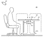
- the airflow generation device 60 is a desk-shaped device installed in an indoor space 70 such as a conference room.
- the airflow generation device 60 includes a suction fan 61 , a louver 62 and a body portion 63 .
- the airflow control system 10 (control device 30) may control such an airflow generation device 60.
- the suction fan 61 is accommodated in the body portion 63 and rotates to generate an airflow (airflow from above to below) that draws the air above the body portion 63 into the body portion 63 . That is, the suction fan 61 sucks the air in the indoor space 70 . As a result, the airflow generation device 60 can suppress the scattering (soaring) of droplets that occur in the indoor space 70 such as a conference room.
- the airflow generation device 60 may include a plurality of suction fans 61 . The amount of suction by the suction fan 61 (that is, the strength of the airflow) is changed based on the control signal transmitted from the control device 30 .
- the louver 62 is a structure for changing the direction of airflow, and is arranged above the suction fan 61 inside the main body 63, for example.
- the louver 62 is, in other words, a guide structure that guides the airflow.
- the louver 62 is, for example, a wing-like structure whose attitude (wing angle) is changed based on a control signal transmitted by the control device 30 .
- the main body 63 is a structure that accommodates the suction fan 61 and the louver 62 and is also used as a desk by people who use the conference room.
- a suction port 63a for sucking air into the body portion 63 by a suction fan 61 is provided on the upper surface of the body portion 63. Further, below the body portion 63 (at the feet of a person), air is sucked from the suction port 63a.
- An exhaust port 63b is provided for exhausting the exhausted air.
- the exhaust port 63b may be connected to a duct leading to the outside of the indoor space 70 . That is, exhaust may be performed to the outside of the indoor space 70 .
- Such an airflow generation device 60 can form an airflow that circulates the air in the indoor space 70 by sucking in the air on the desk and discharging it from the feet (indicated by arrows in FIG. 9).
- FIG. 10 is a flow chart of Operation Example 2 of the airflow control system 10 .
- the control unit 37 of the control device 30 controls the airflow generation device 60 to form a predetermined airflow (indicated by arrows in FIG. 9) in the indoor space 70 (S21).
- the communication unit 31 of the control device 30 receives the image data of the image of the indoor space 70 from the camera 20 (S22).
- the information processing section 32 stores the received image data in the storage section 33 (S23).
- the acquisition unit 34 acquires the image data received by the communication unit 31 and stored in the storage unit 33 (S24), and the specifying unit 35 determines the image that appears in the image based on the acquired image data.
- a two-dimensional human skeleton model is specified (S25).
- the identifying unit 35 identifies skeleton coordinates (three-dimensional coordinate data of each joint) from the identified two-dimensional skeleton model (S26).
- the specifying unit 35 can specify the time-series data of the skeleton coordinates by specifying the skeleton coordinates for each of a plurality of images (frames) forming the moving image.
- the operations of steps S21 to S26 described above are the same as steps S11 to S16 of the first operation example.
- the estimating unit 36 estimates the movement of the person in the image from the specified time-series data of the skeletal coordinates (S27), and based on the estimation result, the person's droplet discharge action (sneezing, coughing, etc.). is detected (S28).
- the operation of ejecting droplets is an example of the specific operation. For example, if the storage unit 33 stores a discriminative model that has learned joint movements when a droplet discharge operation is performed, the estimating unit 36 inputs the time-series data of the skeleton coordinates to the discriminative model. , the ejection action of droplets can be detected.
- the estimation unit 36 estimates the turbulence of the airflow caused by the ejection operation of the droplets (S29).
- the estimation unit 36 estimates airflow turbulence using a predetermined estimation model capable of estimating what kind of airflow turbulence will occur in a predetermined airflow due to, for example, the operation of ejecting droplets.
- the predetermined estimation model is stored in advance in the storage unit 33, for example.
- control unit 37 controls the airflow generation device 60 so that the estimated turbulence of the airflow is suppressed (S30).
- Control of the airflow generation device 60 is performed by transmitting a control signal from the communication unit 31 to the airflow generation device 60 .
- the control unit 37 controls, for example, the suction amount of the suction fan 61 and the attitude of the louver 62, thereby suppressing the estimated turbulence of the airflow and maintaining a predetermined airflow (an airflow close to the predetermined airflow).
- the airflow generation device 60 is operated as follows.
- the control unit 37 may control the suction balance of the plurality of suction fans 61 so as to suppress the estimated turbulence of the airflow.
- the plurality of suction fans 61 includes an auxiliary suction fan 61 for suppressing turbulence of the airflow, which is normally stopped. An airflow (correction airflow) may be generated to suppress the turbulence of the airflow.
- the control unit 37 may more simply increase the amount of air blown (intake amount) of the suction fan 61 to suppress the turbulence of the airflow when the ejection operation of droplets is detected.
- the airflow control system 10 can suppress turbulence in the airflow in the indoor space 70 and continuously form an airflow close to a predetermined airflow in the indoor space 70 . Therefore, the airflow control system 10 can suppress the scattering of droplets in the indoor space 70 by maintaining the suction of air by the airflow generation device 60 .
- a walking motion and a droplet discharging motion are exemplified as specific motions, but the specific motion is not limited to such motions.
- the specific motion may be, for example, a motion of a person fanning himself or another person with a fan.
- the airflow control system 10 may detect a plurality of types of specific actions.
- the airflow control system 10 including the airflow generation device 40 controls the airflow generation device 40 so as to suppress turbulence of the airflow when any of a walking motion, a droplet discharging motion, and a fanning motion is detected. may be controlled.
- the airflow control system 10 includes an acquisition unit 34 that acquires image data of the indoor space 50 (or the indoor space 70) in which an airflow is formed by the airflow generation device 40 and in which a person is located; An identifying unit 35 for identifying the skeletal coordinates of a person based on the image data obtained, an estimating unit 36 for estimating the movement of the person based on the time-series data of the identified skeletal coordinates, and the estimated movement of the person and a control unit 37 that controls the airflow generation device 40 (or the airflow generation device 60) so as to suppress the turbulence of the generated airflow.
- Such an airflow control system 10 can suppress airflow turbulence in the indoor space 50 .
- the airflow control system 10 can maintain the airflow formed in the indoor space.
- the estimating unit 36 detects a specific action of a person by estimating the movement of the person, and the control unit 37 suppresses airflow turbulence caused by the specific action when the specific action is detected.
- the airflow generation device 40 is controlled as follows.
- Such an airflow control system 10 can suppress airflow turbulence caused by specific actions.
- the specific motion is a walking motion.
- Such an airflow control system 10 can suppress airflow turbulence caused by walking.
- the specific action is the ejection action of droplets.
- Such an airflow control system 10 can suppress turbulence in the airflow caused by the operation of ejecting droplets.
- the acquisition unit 34 acquires image data of an image captured by an infrared camera.
- Such an airflow control system 10 can identify the skeletal coordinates of a person even when the indoor space 50 is dark, based on the image data of the image captured by the infrared camera.
- the airflow control method executed by a computer such as the airflow control system 10 includes an acquisition step of acquiring image data of the indoor space 50 in which an airflow is formed by the airflow generation device 40 and in which a person is located; Based on the image data, an identifying step of identifying skeletal coordinates of a person, an estimating step of estimating the motion of the human based on the time-series data of the identified skeletal coordinates, and an airflow generated by the estimated motion of the human. and a control step of controlling the airflow generation device 40 so that the turbulence is suppressed.
- Such an airflow control method can suppress turbulence in the airflow in the indoor space 50 .
- the airflow control method can maintain the airflow formed in the indoor space.
- the airflow control system is implemented by a plurality of devices, but may be implemented as a single device.
- the airflow control system may be implemented as a single device that corresponds to the controller.
- each component included in the airflow control system may be distributed among the plurality of devices in any way.
- processing executed by a specific processing unit may be executed by another processing unit.
- order of multiple processes may be changed, and multiple processes may be executed in parallel.
- each component may be realized by executing a software program suitable for each component.
- Each component may be realized by reading and executing a software program recorded in a recording medium such as a hard disk or a semiconductor memory by a program execution unit such as a CPU or processor.
- each component may be realized by hardware.
- each component may be a circuit (or integrated circuit). These circuits may form one circuit as a whole, or may be separate circuits. These circuits may be general-purpose circuits or dedicated circuits.
- general or specific aspects of the present invention may be implemented in a system, apparatus, method, integrated circuit, computer program, or recording medium such as a computer-readable CD-ROM.
- any combination of systems, devices, methods, integrated circuits, computer programs and recording media may be implemented.
- the present invention may be realized as a program for causing a computer to execute the airflow control method of the above embodiment, or as a computer-readable non-temporary recording medium storing such a program. may be implemented.
Landscapes
- Engineering & Computer Science (AREA)
- Chemical & Material Sciences (AREA)
- General Engineering & Computer Science (AREA)
- Mechanical Engineering (AREA)
- Combustion & Propulsion (AREA)
- Physics & Mathematics (AREA)
- Fluid Mechanics (AREA)
- Signal Processing (AREA)
- Social Psychology (AREA)
- Multimedia (AREA)
- Theoretical Computer Science (AREA)
- General Physics & Mathematics (AREA)
- Human Computer Interaction (AREA)
- Health & Medical Sciences (AREA)
- Psychiatry (AREA)
- General Health & Medical Sciences (AREA)
- Computer Vision & Pattern Recognition (AREA)
- Fuzzy Systems (AREA)
- Mathematical Physics (AREA)
- Air Conditioning Control Device (AREA)
Abstract
Description
[構成]
まず、実施の形態に係る気流制御システムの構成について説明する。図1は、実施の形態に係る気流制御システムの機能構成を示すブロック図である。図2は、実施の形態に係る気流制御システムが備える気流生成装置の概略構成を示す図である。なお、図2は、室内空間50を上方から見た図である。
次に、気流制御システム10の動作例1について説明する。図3は、気流制御システム10の動作例1のフローチャートである。
次に、変形例に係る気流生成装置の構成と、このような気流生成装置を備える気流制御システムの動作例2について説明する。図8は、変形例に係る気流生成装置の外観図である。図9は、変形例に係る気流生成装置の内部構造を示す図である。
以下、このような気流生成装置60を備える気流制御システム10の動作について説明する。図10は、気流制御システム10の動作例2のフローチャートである。
上記実施の形態では、特定動作として、歩行動作及び飛沫の排出動作が例示されたが、特定動作は、このような動作に限定されない。特定動作は、例えば、人が自身または他の人を団扇であおぐ動作などであってもよい。
以上説明したように、気流制御システム10は、気流生成装置40によって気流が形成され、かつ、人が位置する室内空間50(または室内空間70)の画像データを取得する取得部34と、取得された画像データに基づいて、人の骨格座標を特定する特定部35と、特定された骨格座標の時系列データに基づいて、人の動きを推定する推定部36と、推定された人の動きによって生じる気流の乱れが抑制されるように気流生成装置40(または気流生成装置60)を制御する制御部37とを備える。
以上、実施の形態に係る気流制御システム、及び、気流制御方法について説明したが、本発明は、上記実施の形態に限定されるものではない。
20 カメラ
30 制御装置
31 通信部
32 情報処理部
33 記憶部
34 取得部
35 特定部
36 推定部
37 制御部
40、60 気流生成装置
41、61 送風ファン
42、62 ルーバ
50、70 室内空間
63 本体部
63a 吸込口
63b 排気口
Claims (7)
- 気流生成装置によって気流が形成され、かつ、人が位置する室内空間の画像データを取得する取得部と、
取得された前記画像データに基づいて、前記人の骨格座標を特定する特定部と、
特定された前記骨格座標の時系列データに基づいて、前記人の動きを推定する推定部と、
推定された前記人の動きによって生じる前記気流の乱れが抑制されるように前記気流生成装置を制御する制御部とを備える
気流制御システム。 - 前記推定部は、前記人の動きを推定することにより、前記人の特定動作を検出し、
前記制御部は、前記特定動作が検出されたときに、前記特定動作によって生じる前記気流の乱れが抑制されるように前記気流生成装置を制御する
請求項1に記載の気流制御システム。 - 前記特定動作は、歩行動作である
請求項2に記載の気流制御システム。 - 前記特定動作は、飛沫の排出動作である
請求項2に記載の気流制御システム。 - 前記取得部は、赤外カメラによって撮影された画像の前記画像データを取得する
請求項1~4のいずれか1項に記載の気流制御システム。 - 気流生成装置によって気流が形成され、かつ、人が位置する室内空間の画像データを取得する取得ステップと、
取得された前記画像データに基づいて、前記人の骨格座標を特定する特定ステップと、
特定された前記骨格座標の時系列データに基づいて、前記人の動きを推定する推定ステップと、
推定された前記人の動きによって生じる前記気流の乱れが抑制されるように前記気流生成装置を制御する制御ステップとを備える
気流制御方法。 - 請求項6に記載の気流制御方法をコンピュータに実行させるためのプログラム。
Priority Applications (4)
| Application Number | Priority Date | Filing Date | Title |
|---|---|---|---|
| CN202280043913.4A CN117581066A (zh) | 2021-06-30 | 2022-06-17 | 气流控制系统和气流控制方法 |
| US18/573,468 US20240295338A1 (en) | 2021-06-30 | 2022-06-17 | Airflow control system and airflow control method |
| JP2023531804A JP7627882B2 (ja) | 2021-06-30 | 2022-06-17 | 気流制御システム、及び、気流制御方法 |
| EP22832885.2A EP4365501A4 (en) | 2021-06-30 | 2022-06-17 | AIRFLOW CONTROL SYSTEM AND AIRFLOW CONTROL METHOD |
Applications Claiming Priority (2)
| Application Number | Priority Date | Filing Date | Title |
|---|---|---|---|
| JP2021-108428 | 2021-06-30 | ||
| JP2021108428 | 2021-06-30 |
Publications (1)
| Publication Number | Publication Date |
|---|---|
| WO2023276735A1 true WO2023276735A1 (ja) | 2023-01-05 |
Family
ID=84692370
Family Applications (1)
| Application Number | Title | Priority Date | Filing Date |
|---|---|---|---|
| PCT/JP2022/024390 Ceased WO2023276735A1 (ja) | 2021-06-30 | 2022-06-17 | 気流制御システム、及び、気流制御方法 |
Country Status (5)
| Country | Link |
|---|---|
| US (1) | US20240295338A1 (ja) |
| EP (1) | EP4365501A4 (ja) |
| JP (1) | JP7627882B2 (ja) |
| CN (1) | CN117581066A (ja) |
| WO (1) | WO2023276735A1 (ja) |
Families Citing this family (3)
| Publication number | Priority date | Publication date | Assignee | Title |
|---|---|---|---|---|
| GB2641818A (en) * | 2024-06-14 | 2025-12-17 | Dyson Technology Ltd | Control of an airflow appliance |
| GB2641817A (en) * | 2024-06-14 | 2025-12-17 | Dyson Technology Ltd | Control of an airflow appliance |
| GB2641819A (en) * | 2024-06-14 | 2025-12-17 | Dyson Technology Ltd | Control of an airflow appliance |
Citations (9)
| Publication number | Priority date | Publication date | Assignee | Title |
|---|---|---|---|---|
| JPH06101880A (ja) * | 1992-09-18 | 1994-04-12 | Nippon Steel Corp | クリーンルームの空気調和装置 |
| JP2007205601A (ja) * | 2006-01-31 | 2007-08-16 | Nachi Fujikoshi Corp | ロボット及び気流調整システム |
| WO2010016177A1 (ja) * | 2008-08-07 | 2010-02-11 | パナソニック株式会社 | 集塵装置 |
| JP2010117048A (ja) * | 2008-11-11 | 2010-05-27 | Takasago Thermal Eng Co Ltd | 感染防止クリーンブース装置 |
| US20160307032A1 (en) * | 2015-04-14 | 2016-10-20 | Microsoft Technology Licensing, Llc | Two-dimensional infrared depth sensing |
| JP2017219247A (ja) | 2016-06-07 | 2017-12-14 | 三菱電機株式会社 | 空調機制御装置 |
| WO2019239812A1 (ja) * | 2018-06-14 | 2019-12-19 | パナソニックIpマネジメント株式会社 | 情報処理方法、情報処理プログラム及び情報処理システム |
| WO2020044826A1 (ja) * | 2018-08-30 | 2020-03-05 | パナソニックIpマネジメント株式会社 | 飛沫到達範囲制御システム及び飛沫到達範囲制御方法 |
| WO2021039642A1 (ja) * | 2019-08-30 | 2021-03-04 | 国立大学法人大阪大学 | 3次元再構成装置、方法及びプログラム |
Family Cites Families (16)
| Publication number | Priority date | Publication date | Assignee | Title |
|---|---|---|---|---|
| JP4311212B2 (ja) * | 2004-01-26 | 2009-08-12 | ダイキン工業株式会社 | 天井埋込型空気調和装置及びその制御方法 |
| EP2087293A4 (en) * | 2006-11-28 | 2011-04-06 | Lg Electronics Inc | AIR CONDITIONING AND METHOD FOR CONTROLLING AN AIRFLOW THEREWITH |
| JP6505514B2 (ja) * | 2015-06-10 | 2019-04-24 | パナソニック株式会社 | 空気調和機、センサシステムおよびその温冷感推定方法 |
| WO2018029805A1 (ja) | 2016-08-10 | 2018-02-15 | 三菱電機株式会社 | 空気調和機の室内機 |
| JP7109162B2 (ja) | 2017-06-14 | 2022-07-29 | 三菱電機株式会社 | 空気調和機 |
| US11512866B2 (en) * | 2017-06-15 | 2022-11-29 | Mitsubishi Electric Corporation | Indoor unit for air-conditioning apparatus |
| JP7117837B2 (ja) | 2017-09-29 | 2022-08-15 | 株式会社日立ハイテク | 局所クリーン基板搬送装置 |
| CN108592186A (zh) * | 2018-04-12 | 2018-09-28 | 中国建筑股份有限公司 | 大空间的微环境品质控制系统 |
| JP2019220145A (ja) | 2018-06-13 | 2019-12-26 | パナソニック インテレクチュアル プロパティ コーポレーション オブ アメリカPanasonic Intellectual Property Corporation of America | 操作端末、音声入力方法、及びプログラム |
| US12117197B2 (en) | 2018-09-03 | 2024-10-15 | Daikin Industries, Ltd. | Ventilation control apparatus and ventilation system |
| JP7091983B2 (ja) | 2018-10-01 | 2022-06-28 | トヨタ自動車株式会社 | 機器制御装置 |
| WO2020121370A1 (ja) | 2018-12-10 | 2020-06-18 | 三菱電機株式会社 | 空調機、制御装置、空調システム、空調制御方法及びプログラム |
| EP3693198B1 (en) * | 2019-02-07 | 2021-05-19 | Ningbo Geely Automobile Research & Development Co. Ltd. | An air vent device for a ventilation system of a vehicle |
| US20200273200A1 (en) * | 2019-02-25 | 2020-08-27 | Microsoft Technology Licensing, Llc | Camera localization based on skeletal tracking |
| JP7312078B2 (ja) | 2019-10-07 | 2023-07-20 | 株式会社東海理化電機製作所 | 画像処理装置、およびコンピュータプログラム |
| CN111953907B (zh) | 2020-08-28 | 2021-11-23 | 维沃移动通信有限公司 | 构图方法、装置 |
-
2022
- 2022-06-17 US US18/573,468 patent/US20240295338A1/en active Pending
- 2022-06-17 JP JP2023531804A patent/JP7627882B2/ja active Active
- 2022-06-17 WO PCT/JP2022/024390 patent/WO2023276735A1/ja not_active Ceased
- 2022-06-17 EP EP22832885.2A patent/EP4365501A4/en active Pending
- 2022-06-17 CN CN202280043913.4A patent/CN117581066A/zh active Pending
Patent Citations (9)
| Publication number | Priority date | Publication date | Assignee | Title |
|---|---|---|---|---|
| JPH06101880A (ja) * | 1992-09-18 | 1994-04-12 | Nippon Steel Corp | クリーンルームの空気調和装置 |
| JP2007205601A (ja) * | 2006-01-31 | 2007-08-16 | Nachi Fujikoshi Corp | ロボット及び気流調整システム |
| WO2010016177A1 (ja) * | 2008-08-07 | 2010-02-11 | パナソニック株式会社 | 集塵装置 |
| JP2010117048A (ja) * | 2008-11-11 | 2010-05-27 | Takasago Thermal Eng Co Ltd | 感染防止クリーンブース装置 |
| US20160307032A1 (en) * | 2015-04-14 | 2016-10-20 | Microsoft Technology Licensing, Llc | Two-dimensional infrared depth sensing |
| JP2017219247A (ja) | 2016-06-07 | 2017-12-14 | 三菱電機株式会社 | 空調機制御装置 |
| WO2019239812A1 (ja) * | 2018-06-14 | 2019-12-19 | パナソニックIpマネジメント株式会社 | 情報処理方法、情報処理プログラム及び情報処理システム |
| WO2020044826A1 (ja) * | 2018-08-30 | 2020-03-05 | パナソニックIpマネジメント株式会社 | 飛沫到達範囲制御システム及び飛沫到達範囲制御方法 |
| WO2021039642A1 (ja) * | 2019-08-30 | 2021-03-04 | 国立大学法人大阪大学 | 3次元再構成装置、方法及びプログラム |
Non-Patent Citations (1)
| Title |
|---|
| See also references of EP4365501A4 |
Also Published As
| Publication number | Publication date |
|---|---|
| JP7627882B2 (ja) | 2025-02-07 |
| CN117581066A (zh) | 2024-02-20 |
| EP4365501A4 (en) | 2024-10-23 |
| JPWO2023276735A1 (ja) | 2023-01-05 |
| EP4365501A1 (en) | 2024-05-08 |
| US20240295338A1 (en) | 2024-09-05 |
Similar Documents
| Publication | Publication Date | Title |
|---|---|---|
| JP7627882B2 (ja) | 気流制御システム、及び、気流制御方法 | |
| US11846950B2 (en) | Mobile robot and control method thereof | |
| CN111263921B (zh) | 碰撞检测系统和计算机实现方法 | |
| CN107251096B (zh) | 图像捕获装置和方法 | |
| JP5876142B2 (ja) | 存在センサ | |
| KR102021834B1 (ko) | 이동 로봇 시스템 및 그 제어방법 | |
| EP3349087B1 (en) | Moving robot | |
| JP2021003181A (ja) | 咳検出装置、咳検出方法及びプログラム | |
| CN102734193B (zh) | 风扇控制系统、方法及具有该系统的风扇 | |
| US20190184569A1 (en) | Robot based on artificial intelligence, and control method thereof | |
| JP2023509291A (ja) | ジョイント赤外および可視光視覚慣性オブジェクト追跡 | |
| CN114783047B (zh) | 基于边缘计算的室内吸烟检测方法和装置 | |
| US10207409B2 (en) | Image processing method, image processing device, and robot system | |
| TWI428508B (zh) | 風扇控制系統、方法及具有該系統的風扇 | |
| Coaguila et al. | Selecting Vantage Points for an Autonomous Quadcopter Videographer. | |
| CN109812934B (zh) | 送风系统、送风方法及计算机可读存储介质 | |
| JP7702676B2 (ja) | エアシャワー用気流制御システム、及び、エアシャワー用気流制御方法 | |
| WO2016093241A1 (ja) | 位置方位検出装置及び位置方位検出プログラム | |
| CN112901542A (zh) | 风扇控制方法、风扇及存储介质 | |
| JP2021188822A (ja) | 空気調和システム、無人飛行体および空調機器 | |
| US20240364844A1 (en) | Space coupling system and space coupling method | |
| JP7043706B2 (ja) | 制御装置、撮像システム、制御方法、及びプログラム | |
| JP7565483B2 (ja) | 在不在判定装置、換気システム、全館空調システム、監視システム | |
| WO2023148800A1 (ja) | 制御装置、制御システム、制御方法及びプログラム | |
| JP4618470B2 (ja) | 画像処理装置及び方法並びにロボット装置及びその制御方法 |
Legal Events
| Date | Code | Title | Description |
|---|---|---|---|
| 121 | Ep: the epo has been informed by wipo that ep was designated in this application |
Ref document number: 22832885 Country of ref document: EP Kind code of ref document: A1 |
|
| WWE | Wipo information: entry into national phase |
Ref document number: 2023531804 Country of ref document: JP |
|
| WWE | Wipo information: entry into national phase |
Ref document number: 202280043913.4 Country of ref document: CN |
|
| WWE | Wipo information: entry into national phase |
Ref document number: 2022832885 Country of ref document: EP |
|
| NENP | Non-entry into the national phase |
Ref country code: DE |
|
| ENP | Entry into the national phase |
Ref document number: 2022832885 Country of ref document: EP Effective date: 20240130 |