WO2023279862A1 - 图像处理方法、装置和电子设备 - Google Patents
图像处理方法、装置和电子设备 Download PDFInfo
- Publication number
- WO2023279862A1 WO2023279862A1 PCT/CN2022/093914 CN2022093914W WO2023279862A1 WO 2023279862 A1 WO2023279862 A1 WO 2023279862A1 CN 2022093914 W CN2022093914 W CN 2022093914W WO 2023279862 A1 WO2023279862 A1 WO 2023279862A1
- Authority
- WO
- WIPO (PCT)
- Prior art keywords
- image
- field
- view
- images
- frame
- Prior art date
- Legal status (The legal status is an assumption and is not a legal conclusion. Google has not performed a legal analysis and makes no representation as to the accuracy of the status listed.)
- Ceased
Links
Images




Classifications
-
- G—PHYSICS
- G06—COMPUTING OR CALCULATING; COUNTING
- G06T—IMAGE DATA PROCESSING OR GENERATION, IN GENERAL
- G06T5/00—Image enhancement or restoration
- G06T5/50—Image enhancement or restoration using two or more images, e.g. averaging or subtraction
-
- G—PHYSICS
- G06—COMPUTING OR CALCULATING; COUNTING
- G06N—COMPUTING ARRANGEMENTS BASED ON SPECIFIC COMPUTATIONAL MODELS
- G06N3/00—Computing arrangements based on biological models
- G06N3/02—Neural networks
- G06N3/08—Learning methods
-
- G—PHYSICS
- G06—COMPUTING OR CALCULATING; COUNTING
- G06T—IMAGE DATA PROCESSING OR GENERATION, IN GENERAL
- G06T3/00—Geometric image transformations in the plane of the image
- G06T3/40—Scaling of whole images or parts thereof, e.g. expanding or contracting
- G06T3/4015—Image demosaicing, e.g. colour filter arrays [CFA] or Bayer patterns
-
- G—PHYSICS
- G06—COMPUTING OR CALCULATING; COUNTING
- G06T—IMAGE DATA PROCESSING OR GENERATION, IN GENERAL
- G06T3/00—Geometric image transformations in the plane of the image
- G06T3/40—Scaling of whole images or parts thereof, e.g. expanding or contracting
- G06T3/4046—Scaling of whole images or parts thereof, e.g. expanding or contracting using neural networks
-
- G—PHYSICS
- G06—COMPUTING OR CALCULATING; COUNTING
- G06T—IMAGE DATA PROCESSING OR GENERATION, IN GENERAL
- G06T5/00—Image enhancement or restoration
- G06T5/60—Image enhancement or restoration using machine learning, e.g. neural networks
-
- G—PHYSICS
- G06—COMPUTING OR CALCULATING; COUNTING
- G06T—IMAGE DATA PROCESSING OR GENERATION, IN GENERAL
- G06T5/00—Image enhancement or restoration
- G06T5/70—Denoising; Smoothing
-
- G—PHYSICS
- G06—COMPUTING OR CALCULATING; COUNTING
- G06T—IMAGE DATA PROCESSING OR GENERATION, IN GENERAL
- G06T5/00—Image enhancement or restoration
- G06T5/90—Dynamic range modification of images or parts thereof
-
- G—PHYSICS
- G06—COMPUTING OR CALCULATING; COUNTING
- G06T—IMAGE DATA PROCESSING OR GENERATION, IN GENERAL
- G06T7/00—Image analysis
- G06T7/30—Determination of transform parameters for the alignment of images, i.e. image registration
-
- G—PHYSICS
- G06—COMPUTING OR CALCULATING; COUNTING
- G06V—IMAGE OR VIDEO RECOGNITION OR UNDERSTANDING
- G06V10/00—Arrangements for image or video recognition or understanding
- G06V10/40—Extraction of image or video features
- G06V10/56—Extraction of image or video features relating to colour
-
- G—PHYSICS
- G06—COMPUTING OR CALCULATING; COUNTING
- G06V—IMAGE OR VIDEO RECOGNITION OR UNDERSTANDING
- G06V10/00—Arrangements for image or video recognition or understanding
- G06V10/40—Extraction of image or video features
- G06V10/60—Extraction of image or video features relating to illumination properties, e.g. using a reflectance or lighting model
-
- H—ELECTRICITY
- H04—ELECTRIC COMMUNICATION TECHNIQUE
- H04N—PICTORIAL COMMUNICATION, e.g. TELEVISION
- H04N23/00—Cameras or camera modules comprising electronic image sensors; Control thereof
- H04N23/45—Cameras or camera modules comprising electronic image sensors; Control thereof for generating image signals from two or more image sensors being of different type or operating in different modes, e.g. with a CMOS sensor for moving images in combination with a charge-coupled device [CCD] for still images
-
- H—ELECTRICITY
- H04—ELECTRIC COMMUNICATION TECHNIQUE
- H04N—PICTORIAL COMMUNICATION, e.g. TELEVISION
- H04N9/00—Details of colour television systems
- H04N9/64—Circuits for processing colour signals
- H04N9/73—Colour balance circuits, e.g. white balance circuits or colour temperature control
-
- G—PHYSICS
- G06—COMPUTING OR CALCULATING; COUNTING
- G06T—IMAGE DATA PROCESSING OR GENERATION, IN GENERAL
- G06T2207/00—Indexing scheme for image analysis or image enhancement
- G06T2207/10—Image acquisition modality
- G06T2207/10016—Video; Image sequence
-
- G—PHYSICS
- G06—COMPUTING OR CALCULATING; COUNTING
- G06T—IMAGE DATA PROCESSING OR GENERATION, IN GENERAL
- G06T2207/00—Indexing scheme for image analysis or image enhancement
- G06T2207/10—Image acquisition modality
- G06T2207/10024—Color image
-
- G—PHYSICS
- G06—COMPUTING OR CALCULATING; COUNTING
- G06T—IMAGE DATA PROCESSING OR GENERATION, IN GENERAL
- G06T2207/00—Indexing scheme for image analysis or image enhancement
- G06T2207/10—Image acquisition modality
- G06T2207/10141—Special mode during image acquisition
- G06T2207/10144—Varying exposure
-
- G—PHYSICS
- G06—COMPUTING OR CALCULATING; COUNTING
- G06T—IMAGE DATA PROCESSING OR GENERATION, IN GENERAL
- G06T2207/00—Indexing scheme for image analysis or image enhancement
- G06T2207/20—Special algorithmic details
- G06T2207/20081—Training; Learning
-
- G—PHYSICS
- G06—COMPUTING OR CALCULATING; COUNTING
- G06T—IMAGE DATA PROCESSING OR GENERATION, IN GENERAL
- G06T2207/00—Indexing scheme for image analysis or image enhancement
- G06T2207/20—Special algorithmic details
- G06T2207/20084—Artificial neural networks [ANN]
-
- G—PHYSICS
- G06—COMPUTING OR CALCULATING; COUNTING
- G06T—IMAGE DATA PROCESSING OR GENERATION, IN GENERAL
- G06T2207/00—Indexing scheme for image analysis or image enhancement
- G06T2207/20—Special algorithmic details
- G06T2207/20212—Image combination
- G06T2207/20221—Image fusion; Image merging
Definitions
- the present application relates to the field of image processing, in particular to an image processing method, device and electronic equipment.
- the mobile phone is configured with two cameras, one is a main camera, and the other is a wide-angle camera or a telephoto camera.
- the field of view of the wide-angle camera is larger than that of the main camera, which is suitable for close-up shooting
- the field of view of the telephoto camera is smaller than that of the main camera, which is suitable for long-range shooting.
- the fused image will have poor stereoscopic effect and poor quality because the field of view angles of the two cameras do not match. poor.
- the two images obtained by a mobile phone using such a dual camera there are parts where the field of view overlaps, and there are also parts where the field of view does not overlap. If the two images are directly fused, then the part of the final captured image where the field of view angles overlap has high definition, and the part that does not overlap has low definition, so that the captured image will have inconsistencies in the definition of the central part and surrounding parts.
- the problem is that there will be a fusion boundary on the image, which will affect the imaging effect.
- the application provides an image processing method, device and electronic equipment, by adding a reference coordinate layer to one of the two images with different viewing angles, and then inputting it into the deep learning network model for processing to obtain the corresponding image to improve shooting image quality.
- an image processing method comprising:
- the multiple frames of original images are images taken for the same scene to be shot.
- the multiple frames of original images include: a first field of view image and a second field of view image, and the field of view corresponding to the first field of view image
- the field angle is different from the field angle corresponding to the second field of view image;
- a reference coordinate layer is added to the second field of view image, and the reference coordinate layer is used to reflect the field angle corresponding to the second field of view image and the first
- the mapping relationship between the viewing angles corresponding to the viewing angle images; according to the first viewing angle image, the second viewing angle image and the reference coordinate layer, the layer set is obtained; the deep learning network model is used to process the layer set,
- a first enhanced image is obtained; the first enhanced image is located in RGB color space; and a second enhanced image is obtained according to the first enhanced image.
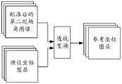
- the embodiment of the present application provides an image processing method, by obtaining the first field of view image and the second field of view image corresponding to different field of view, and adding a reference coordinate layer to the second field of view image to form a map
- the layer set and then use the deep learning network model to process the layer set to obtain the first enhanced image, and then obtain the second enhanced image according to the first enhanced image.
- the reference coordinate layer reflects the mapping relationship between the field angle corresponding to the second field of view image and the field angle corresponding to the first field of view image, thus, by adding a reference coordinate layer, different viewing angles can be added.
- the mapping relationship information between field angles enables subsequent adjustments to be made according to the mapping relationship between different field angles, so that more details can be preserved, and the fusion is more natural, thereby achieving the purpose of improving image quality.
- the deep learning network model can perform multiple processes on the layer set at the same time, such as noise reduction, demosaicing, color fusion and field of view fusion, etc., avoiding the accumulation of errors caused by serial processing, thus, also The sharpness of the image can be improved.
- the method before adding a reference coordinate layer to the second FOV image, the method further includes: performing the first FOV image and/or the second FOV image A first process is performed, and the first process includes: registration.
- the accuracy in subsequent image processing can be improved.
- the first field of view image includes one or more of the following: multiple frames of the first image, multiple frames of the second image, and at least one frame of the third image; wherein, the multiple frames
- the first image includes at least one frame of long-exposure image and at least one frame of short-exposure image
- the second image is a Bayer pattern image with normal exposure
- the third image is a grayscale image.
- the first image is a Bayer format image or a grayscale image.
- the second field-of-view image is a Bayer pattern image or a grayscale image.
- registering the second field of view images includes: taking the first frame of the second image as a reference frame , to perform registration on the second field of view image.
- the method further includes: according to the second image in the first frame and the registered second FOV image, The preset coordinate layer performs perspective transformation to obtain a reference coordinate layer, and the preset coordinate layer is used to reflect the difference between the field angle corresponding to the preset second field of view image and the field angle corresponding to the first field of view image mapping relationship between them.
- the second field of view image is registered, so the preset coordinate layer can be adjusted according to the registered second field of view image , to obtain a reference coordinate layer that can more accurately reflect the mapping relationship between the field angle corresponding to the first field of view image and the field angle corresponding to the second field of view image.
- the preset coordinate layer includes an overlapping area; the overlapping area is used to represent: the image sticker with a smaller viewing angle in the first frame of the second image and the second viewing angle image The area corresponding to an image with a larger field of view.
- the first processing further includes: black level correction.
- the first processing further includes : Automatic white balance.
- the first processing further includes: channel splitting; wherein, channel splitting refers to splitting a Bayer format image into multiple single-channel sublayers to be enhanced, each The single-channel sublayer to be enhanced contains only one color channel signal.
- channel splitting refers to splitting a Bayer format image into multiple single-channel sublayers to be enhanced, each The single-channel sublayer to be enhanced contains only one color channel signal.
- the first processing further includes: adding a variance layer; wherein, the variance layer includes a plurality of pixels, and the variance value corresponding to each pixel is determined by the sensitivity corresponding to the original image.
- the variance layer includes a plurality of pixels, and the variance value corresponding to each pixel is determined by the sensitivity corresponding to the original image.
- the prior information can be increased, so that the follow-up can be based on different noises Different levels of noise reduction can be performed to preserve more details and achieve the purpose of improving the clarity of the image.
- the deep learning network model is used to process the layer set to obtain the first enhanced image, including: using the deep learning network model to perform noise reduction, demosaicing, color fusion and visual The field angles are fused to obtain the first enhanced image.
- the deep learning network model can perform multiple processes at the same time, the accumulation of errors caused by serial processing is avoided, thereby improving the clarity of the image.
- obtaining the second enhanced image according to the first enhanced image includes: performing enhancement processing on the first enhanced image to obtain the second enhanced image, and the enhancement processing includes color enhancement processing and / or brightness enhancement processing.
- performing color enhancement and/or brightness enhancement on the first enhanced image can enhance the visual effect of the image, so that the enhanced image content and image color can better meet the user's visual needs.
- performing enhancement processing on the first enhanced image to obtain a second enhanced image includes: segmenting the first enhanced image by using a segmentation model to obtain a mask map; according to the first enhanced image and a mask map, using a tone mapping model to obtain a gain coefficient map; the gain coefficient map includes a plurality of pixels and a corresponding gain value for each pixel; multiplying the first enhanced image by the gain coefficient map to obtain a second enhanced image.
- non-linear enhancement can be performed on the first enhanced image, thus, the first enhanced image can be processed more delicately.
- the gain coefficient map includes 3 frames of color gain coefficient map and/or 1 frame of brightness gain coefficient map, and each frame of color gain coefficient map only enhances one color, and the brightness gain The coefficient map is used to enhance the brightness.
- the first processing when the first processing is not performed on multiple frames of first images in the first field of view image, but the first processing is performed on the second field of view image, according to the first The field of view image, the second field of view image and the reference coordinate layer to obtain the layer set, including: according to the first field of view image except for the images of multiple frames of the first image, the second field of view image and Refer to the coordinate layer to get the layer set.
- the method before using the segmentation model to obtain the mask map corresponding to the first enhanced image, the method further includes: using the long-exposure image and the short-exposure image in the multiple frames of the first image, Perform long and short exposure fusion processing on the first enhanced image to obtain an intermediate enhanced image; use the intermediate enhanced image as the first enhanced image.
- the long and short exposure fusion processing is performed on the first enhanced image, so that the details of the dark area and the overexposed area in the first enhanced image can be improved, and an intermediate enhanced image with higher definition can be obtained.
- the long-exposure image and the short-exposure image are used to perform long-short-exposure fusion processing on the first enhanced image to obtain an intermediate enhanced image, including: combining the first enhanced image with the first image to be fused Perform fusion to obtain a first intermediate fusion image; fuse the first intermediate fusion image and the second image to be fused to obtain the intermediate enhanced image; wherein, the first image to be fused and the second image to be fused are respectively long exposure images and short exposure images.
- the method further includes: performing color space conversion on the second enhanced image to obtain the first target image in the YUV color space.
- performing color space conversion can reduce the amount of subsequent calculations and save storage space.
- the deep learning network model and the segmentation model are respectively any one of the Unet model, the Resnet model and the PSPnet model.
- the tone mapping model is any one of Unet model, Resnet model and Hdrnet model.
- an image processing apparatus in a second aspect, includes a unit for performing each step in the above first aspect or any possible implementation manner of the first aspect.
- an image processing device including: a receiving interface and a processor; the receiving interface is used to obtain multiple frames of original images from an electronic device, the multiple frames of original images are images taken for the same scene to be shot, and multiple The frame original image includes: a first field of view image and a second field of view image, and the field of view corresponding to the first field of view image is different from the field of view corresponding to the second field of view image; the processor is used to call
- the computer program stored in the memory is used to execute the processing steps in the image processing method provided in the first aspect or any possible implementation manner of the first aspect.
- an electronic device including a camera module, a processor, and a memory; the camera module is used to obtain multiple frames of original images, and the multiple frames of original images are images taken for the same scene to be shot, and the multiple frames
- the original image includes: a first field of view image and a second field of view image, and the field of view corresponding to the first field of view image is different from the field of view corresponding to the second field of view image; the memory is used for storing A computer program running on the processor; the processor is configured to execute the processing steps in the image processing method provided in the first aspect or any possible implementation manner of the first aspect.
- the camera module includes a color camera, a black-and-white camera, and a third camera
- the color camera and the black-and-white camera are used to take pictures of the same scene to be shot at a first field of view
- the third The camera is used to take pictures of the scene to be shot with a second field of view; the first field of view is different from the second field of view; the color camera is used to obtain multiple frames of the first image and multiple frames after the processor obtains the photographing instruction
- the second image, the multi-frame first image includes at least one frame of long exposure image and one frame of short exposure image; the second image is a Bayer format image with normal exposure; the black and white camera is used to obtain at least one frame after the processor obtains the camera instruction
- the camera module includes a color camera, a black-and-white camera, and a third camera
- the color camera and the black-and-white camera are used to take pictures of the same scene to be shot at a first field of view
- the third The camera is used to take pictures of the scene to be shot with a second field of view; the first field of view is different from the second field of view; the color camera is used to obtain multiple frames of second images after the processor obtains the photographing instruction,
- the second image is a Bayer format image with normal exposure;
- the black and white camera is used to obtain multiple frames of the first image and at least one frame of the third image after the processor obtains the camera instruction, and the multiple frames of the first image include at least one frame of long-exposure image and a short-exposure image;
- the third image is a grayscale image; and the third camera is used to acquire at least one frame of a second field-of-view image after the processor acquires the photographing instruction.
- a chip including: a processor, configured to call and run a computer program from a memory, so that a device installed with the chip executes the chip as provided in the first aspect or any possible implementation manner of the first aspect. The steps of processing in the image processing method.
- a computer-readable storage medium stores a computer program, and the computer program includes program instructions.
- the program instructions When executed by a processor, the processor executes the first aspect or the first method. Steps of performing processing in the image processing method provided in any possible implementation manner of the aspect.
- a computer program product includes a computer-readable storage medium storing a computer program, and the computer program enables the computer to execute the image provided in the first aspect or any possible implementation manner of the first aspect The step in the processing method that performs the processing.
- the image processing method, device and electronic equipment provided by this application form The layer set, and then use the deep learning network model to process the layer set to obtain a first enhanced image, and then obtain a second enhanced image based on the first enhanced image.
- the reference coordinate layer reflects the mapping relationship between the field angle corresponding to the second field of view image and the field angle corresponding to the first field of view image, thus, by adding a reference coordinate layer, different viewing angles can be added.
- the mapping relationship information between field angles enables subsequent adjustments to be made according to the mapping relationship between different field angles, so that more details can be preserved, and the fusion is more natural, thereby achieving the purpose of improving image quality.
- the deep learning network model can perform multiple processes on the layer set at the same time, such as noise reduction, demosaicing, color fusion and field of view fusion, etc., avoiding the accumulation of errors caused by serial processing, thus, also The sharpness of the image can be improved.
- FIG. 1 is a schematic diagram of processing images captured by dual cameras provided by the related art
- FIG. 2 is a schematic structural diagram of an electronic device provided in an embodiment of the present application.
- FIG. 3 is a hardware architecture diagram of an image processing device provided in an embodiment of the present application.
- FIG. 4 is a schematic flow diagram of an image processing method provided in an embodiment of the present application.
- FIG. 5 is a schematic flow chart of registering multiple frames of second images provided by an embodiment of the present application.
- FIG. 6 is a schematic diagram of obtaining a reference coordinate layer provided by an embodiment of the present application.
- FIG. 7 is a schematic diagram of performing perspective transformation processing on a preset coordinate layer according to an embodiment of the present application.
- FIG. 8 is a schematic diagram of performing black level correction on a second image according to an embodiment of the present application.
- FIG. 9 is a schematic diagram of channel splitting of a second image provided by an embodiment of the present application.
- FIG. 10 is a schematic diagram of performing channel splitting on a second image and adding a variance layer according to an embodiment of the present application
- Fig. 11 is a schematic diagram of the variance layer provided by the embodiment of the present application.
- FIG. 12 is a schematic flow diagram of obtaining the first enhanced image corresponding to the layer set by using the deep learning network model provided by the embodiment of the present application;
- FIG. 13 is a schematic flowchart of another image processing method provided by the embodiment of the present application.
- FIG. 14 is a schematic flow diagram for obtaining a second enhanced image by performing enhancement processing on the first enhanced image according to an embodiment of the present application
- FIG. 15 is a schematic flowchart of another image processing method provided by the embodiment of the present application.
- FIG. 16 is another schematic flow diagram of performing enhancement processing on the first enhanced image to obtain the second enhanced image provided by the embodiment of the present application;
- FIG. 17 is a schematic flowchart of another image processing method provided by the embodiment of the present application.
- FIG. 18 is a schematic flowchart of another image processing method provided by the embodiment of the present application.
- FIG. 19 is a schematic flowchart of another image processing method provided by the embodiment of the present application.
- FIG. 20 is a schematic flowchart of another image processing method provided in the embodiment of the present application.
- FIG. 21 is a schematic flowchart of another image processing method provided by the embodiment of the present application.
- FIG. 22 is a schematic flowchart of another image processing method provided by the embodiment of the present application.
- FIG. 23 is a schematic flowchart of another image processing method provided by the embodiment of the present application.
- FIG. 24 is a schematic structural diagram of an image processing device provided by an embodiment of the present application.
- Fig. 25 is a schematic structural diagram of a chip provided by the embodiment of the application.
- a relationship means that there may be three kinds of relationships, for example, A and/or B means: A exists alone, A and B exist simultaneously, and B exists alone.
- plural refers to two or more than two.
- first and second are used for descriptive purposes only, and cannot be understood as indicating or implying relative importance or implicitly specifying the quantity of indicated technical features. Thus, a feature defined as “first” and “second” may explicitly or implicitly include one or more of these features. In the description of this embodiment, unless otherwise specified, “plurality” means two or more.
- RGB (red, green, blue) color space refers to a color model related to the structure of the human visual system. According to the structure of the human eye, all colors are seen as different combinations of red, green and blue.
- YUV color space refers to a color coding method, Y represents brightness, U and V represent chroma.
- RGB color space focuses on the human eye's perception of color, while the YUV color space focuses on the sensitivity of vision to brightness.
- RGB color space and YUV color space can be converted to each other.
- the pixel value refers to a group of color components corresponding to each pixel in the color image located in the RGB color space.
- each pixel corresponds to a group of three primary color components, wherein the three primary color components are red component R, green component G and blue component B respectively.
- Bayer pattern color filter array when the image is converted from the actual scene to image data, usually the image sensor receives the red channel signal, the green channel signal and the blue channel signal respectively, three information of three channel signals, and then synthesize the information of three channel signals into a color image.
- CFA color filter array
- the surface is covered with a color filter array to obtain the information of the three channel signals.
- the Bayer format color filter array means that the filters are arranged in a checkerboard format. For example, the smallest repeating unit in the Bayer format color filter array is: one filter for obtaining the red channel signal, two filters for obtaining the green channel signal , a filter for obtaining the blue channel signal is arranged in a 2 ⁇ 2 manner.
- a Bayer image that is, an image output by an image sensor based on a Bayer format color filter array.
- the pixels of multiple colors in this image are arranged in a Bayer pattern.
- each pixel in the Bayer format image only corresponds to a channel signal of one color.
- green pixels pixels corresponding to the green channel signal
- blue pixels pixels corresponding to the blue channel signal
- red pixels pixels corresponding to the blue channel signal
- Pixels corresponding to the red channel signal each account for 25% of all pixels.
- the minimum repeating unit of the Bayer format image is: one red pixel, two green pixels and one blue pixel are arranged in a 2 ⁇ 2 manner.
- Grayscale image a grayscale image is a single-channel image, used to represent different brightness levels, the brightest is all white, and the darkest is all black. That is, each pixel in a grayscale image corresponds to a different degree of brightness between black and white.
- 256 gray scales (0th grayscale to grayscale 255 grayscale).
- Binary image means that each pixel on the image has only two possible values or grayscale states.
- the gray value corresponding to the pixel included in the image can only be 0 or 255, 0 and 255 represent white and black respectively; or in other words, the corresponding value of the pixel in the image can only be 0 or 1, 0 and 1 respectively Represents white and black.
- Registration refers to the matching of geographic coordinates of different images obtained by different imaging methods in the same area. Among them, it includes the processing of three aspects: geometric correction, projection transformation and unified scale.
- Black level correction due to the presence of dark current in the image sensor, when there is no light, the pixels also have a certain output voltage, and the pixels at different positions may correspond to different output voltages, therefore, it is necessary to correct The output voltage corresponding to the bright (ie, black) pixel is corrected.
- dead point is the white point in the output image in a completely black environment, and the black point in the output image in a bright environment.
- the three primary color channel signals should have a linear response relationship with the ambient brightness, but due to poor signal output by the image sensor, white or black spots may appear, for this, it can be automatically detected and repaired automatically, or, establish The bad pixel linked list repairs bad pixels at fixed positions.
- a point refers to a pixel.
- Noise reduction refers to the process of reducing noise in an image. Common methods include mean filtering, Gaussian filtering, and bilateral filtering.
- Field of view which is used to indicate the maximum angle range that the camera can capture. If the object to be photographed is within the angle range, the object to be photographed will be captured by the camera. If the object to be photographed is outside the angle range, the object to be photographed will not be captured by the camera.
- FOV Field of view
- the camera can be divided into a main camera, a wide-angle camera, and a telephoto camera due to different field of view angles.
- the field of view of the wide-angle camera is larger than that of the main camera, and the focal length is smaller, which is suitable for close-up shooting; while the field of view of the telephoto camera is smaller than that of the main camera, and the focal length is longer. Suitable for remote shooting.
- the mobile phone is configured with two cameras, one is a main camera, and the other is a wide-angle camera or a telephoto camera, or the two cameras are respectively a wide-angle camera and a telephoto camera.
- the angle of view of the wide-angle camera is larger than that of the main camera, and the angle of view of the telephoto camera is smaller than that of the main camera. Then, the image taken by the main camera and the image taken by the wide-angle camera, or; the image taken by the main camera and the image taken by the telephoto camera are simply fused; Simple fusion.
- FIG. 1 shows a schematic diagram of processing images captured by dual cameras in a related technology.
- the first field of view image taken by the main camera is usually filled in the second field of view image taken by the wide-angle camera according to the size of the field of view, or the telephoto camera
- the captured image of the first field of view is filled in the image of the second field of view captured by the main camera or the wide-angle camera.
- the fused image will have poor stereoscopic effect and poor quality.
- the two images obtained by a mobile phone using such a dual camera there are parts where the field of view overlaps, and there are also parts where the field of view does not overlap. If the two images are fused directly, the overlapping parts and non-overlapping parts of the final captured image may not be in alignment, and part of the content may be broken or deformed.
- the overlapping part of the field of view may have high definition, and the non-overlapping part may have low definition, so that the captured image will have the problem of inconsistency in the definition of the central part and the surrounding part, that is, there will be a fusion boundary on the image, which will affect the imaging. Effect.
- the embodiment of the present application provides an image processing method, by acquiring the first field of view image and the second field of view image corresponding to different field of view, and adding a reference coordinate map to the second field of view image Layers to form a layer set, and then use the deep learning network model to process the layer set to obtain the first enhanced image, and then obtain the second enhanced image based on the first enhanced image.
- the reference coordinate layer reflects the mapping relationship between the field angle corresponding to the second field of view image and the field angle corresponding to the first field of view image, thus, by adding a reference coordinate layer, different viewing angles can be added.
- the mapping relationship information between field angles enables subsequent adjustments to be made according to the mapping relationship between different field angles, so that more details can be preserved, and the fusion is more natural, thereby achieving the purpose of improving image quality.
- the image processing method provided in the embodiment of the present application may be applicable to various electronic devices, and correspondingly, the image processing apparatus provided in the embodiment of the present application may be electronic devices in various forms.
- the electronic device may be various camera devices such as SLR cameras and card players, mobile phones, tablet computers, wearable devices, vehicle-mounted devices, augmented reality (augmented reality, AR)/virtual reality (virtual reality) reality, VR) equipment, notebook computer, ultra-mobile personal computer (ultra-mobile personal computer, UMPC), netbook, personal digital assistant (personal digital assistant, PDA), etc., or other equipment or devices capable of image processing,
- camera devices such as SLR cameras and card players, mobile phones, tablet computers, wearable devices, vehicle-mounted devices, augmented reality (augmented reality, AR)/virtual reality (virtual reality) reality, VR) equipment, notebook computer, ultra-mobile personal computer (ultra-mobile personal computer, UMPC), netbook, personal digital assistant (personal digital assistant, PDA), etc., or other equipment or devices capable of image processing
- the embodiment of the present application does not set any limitation on the specific type of the electronic device.
- FIG. 2 shows a schematic structural diagram of an electronic device 100 provided in an embodiment of the present application.
- the electronic device 100 may include a processor 110, an external memory interface 120, an internal memory 121, a universal serial bus (universal serial bus, USB) interface 130, a charging management module 140, a power management module 141, a battery 142, an antenna 1, and an antenna 2 , mobile communication module 150, wireless communication module 160, audio module 170, speaker 170A, receiver 170B, microphone 170C, earphone jack 170D, sensor module 180, button 190, motor 191, indicator 192, camera 193, display screen 194, and A subscriber identification module (subscriber identification module, SIM) card interface 195 and the like.
- SIM subscriber identification module
- the sensor module 180 may include a pressure sensor 180A, a gyroscope sensor 180B, an air pressure sensor 180C, a magnetic sensor 180D, an acceleration sensor 180E, a distance sensor 180F, a proximity light sensor 180G, a fingerprint sensor 180H, a temperature sensor 180J, a touch sensor 180K, an ambient light sensor 180L, bone conduction sensor 180M, etc.
- the processor 110 may include one or more processing units, for example: the processor 110 may include an application processor (application processor, AP), a modem processor, a graphics processing unit (graphics processing unit, GPU), an image signal processor (image signal processor, ISP), controller, video codec, digital signal processor (digital signal processor, DSP), baseband processor, and/or neural network processor (neural-network processing unit, NPU), etc. Wherein, different processing units may be independent devices, or may be integrated in one or more processors.
- application processor application processor, AP
- modem processor graphics processing unit
- GPU graphics processing unit
- image signal processor image signal processor
- ISP image signal processor
- controller video codec
- digital signal processor digital signal processor
- baseband processor baseband processor
- neural network processor neural-network processing unit
- the controller may be the nerve center and command center of the electronic device 100 .
- the controller can generate an operation control signal according to the instruction opcode and timing signal, and complete the control of fetching and executing the instruction.
- a memory may also be provided in the processor 110 for storing instructions and data.
- the memory in processor 110 is a cache memory.
- the memory may hold instructions or data that the processor 110 has just used or recycled. If the processor 110 needs to use the instruction or data again, it can be called directly from the memory. Repeated access is avoided, and the waiting time of the processor 110 is reduced, thereby improving the efficiency of the system.
- the processor 110 may run the software code of the image processing method provided in the embodiment of the present application to capture an image with higher definition.
- processor 110 may include one or more interfaces.
- the interface may include an integrated circuit (inter-integrated circuit, I2C) interface, an integrated circuit built-in audio (inter-integrated circuit sound, I2S) interface, a pulse code modulation (pulse code modulation, PCM) interface, a universal asynchronous transmitter (universal asynchronous receiver/transmitter, UART) interface, mobile industry processor interface (mobile industry processor interface, MIPI), general-purpose input and output (general-purpose input/output, GPIO) interface, subscriber identity module (subscriber identity module, SIM) interface, and /or universal serial bus (universal serial bus, USB) interface, etc.
- I2C integrated circuit
- I2S integrated circuit built-in audio
- PCM pulse code modulation
- PCM pulse code modulation
- UART universal asynchronous transmitter
- MIPI mobile industry processor interface
- GPIO general-purpose input and output
- subscriber identity module subscriber identity module
- SIM subscriber identity module
- USB universal serial bus
- the MIPI interface can be used to connect the processor 110 with peripheral devices such as the display screen 194 and the camera 193 .
- MIPI interface includes camera serial interface (camera serial interface, CSI), display serial interface (display serial interface, DSI), etc.
- the processor 110 communicates with the camera 193 through the CSI interface to realize the shooting function of the electronic device 100 .
- the processor 110 communicates with the display screen 194 through the DSI interface to realize the display function of the electronic device 100 .
- the GPIO interface can be configured by software.
- the GPIO interface can be configured as a control signal or as a data signal.
- the GPIO interface can be used to connect the processor 110 with the camera 193 , the display screen 194 , the wireless communication module 160 , the audio module 170 , the sensor module 180 and so on.
- the GPIO interface can also be configured as an I2C interface, I2S interface, UART interface, MIPI interface, etc.
- the USB interface 130 is an interface conforming to the USB standard specification, specifically, it can be a Mini USB interface, a Micro USB interface, a USB Type C interface, and the like.
- the USB interface 130 can be used to connect a charger to charge the electronic device 100 , and can also be used to transmit data between the electronic device 100 and peripheral devices. It can also be used to connect headphones and play audio through them. This interface can also be used to connect other electronic devices, such as AR devices.
- the interface connection relationship between the modules shown in the embodiment of the present application is only a schematic illustration, and does not constitute a structural limitation of the electronic device 100 .
- the electronic device 100 may also adopt different interface connection manners in the foregoing embodiments, or a combination of multiple interface connection manners.
- the charging management module 140 is configured to receive a charging input from a charger.
- the power management module 141 is used for connecting the battery 142 , the charging management module 140 and the processor 110 .
- the power management module 141 receives the input from the battery 142 and/or the charging management module 140 to provide power for the processor 110 , the internal memory 121 , the display screen 194 , the camera 193 , and the wireless communication module 160 .
- the wireless communication function of the electronic device 100 can be realized by the antenna 1 , the antenna 2 , the mobile communication module 150 , the wireless communication module 160 , a modem processor, a baseband processor, and the like.
- Antenna 1 and Antenna 2 are used to transmit and receive electromagnetic wave signals.
- Each antenna in electronic device 100 may be used to cover single or multiple communication frequency bands. Different antennas can also be multiplexed to improve the utilization of the antennas.
- Antenna 1 can be multiplexed as a diversity antenna of a wireless local area network.
- the antenna may be used in conjunction with a tuning switch.
- the mobile communication module 150 can provide wireless communication solutions including 2G/3G/4G/5G applied on the electronic device 100 .
- the mobile communication module 150 may include at least one filter, switch, power amplifier, low noise amplifier (low noise amplifier, LNA) and the like.
- the mobile communication module 150 can receive electromagnetic waves through the antenna 1, filter and amplify the received electromagnetic waves, and send them to the modem processor for demodulation.
- the mobile communication module 150 can also amplify the signals modulated by the modem processor, and convert them into electromagnetic waves through the antenna 1 for radiation.
- at least part of the functional modules of the mobile communication module 150 may be set in the processor 110 .
- at least part of the functional modules of the mobile communication module 150 and at least part of the modules of the processor 110 may be set in the same device.
- the wireless communication module 160 can provide wireless local area networks (wireless local area networks, WLAN) (such as wireless fidelity (Wireless Fidelity, Wi-Fi) network), bluetooth (bluetooth, BT), global navigation satellite, etc. applied on the electronic device 100.
- System global navigation satellite system, GNSS
- frequency modulation frequency modulation, FM
- near field communication technology near field communication, NFC
- infrared technology infrared, IR
- the wireless communication module 160 may be one or more devices integrating at least one communication processing module.
- the wireless communication module 160 receives electromagnetic waves via the antenna 2, frequency-modulates and filters the electromagnetic wave signals, and sends the processed signals to the processor 110.
- the wireless communication module 160 can also receive the signal to be sent from the processor 110 , frequency-modulate it, amplify it, and convert it into electromagnetic waves through the antenna 2 for radiation.
- the antenna 1 of the electronic device 100 is coupled to the mobile communication module 150, and the antenna 2 is coupled to the wireless communication module 160, so that the electronic device 100 can communicate with the network and other devices through wireless communication technology.
- the wireless communication technology may include global system for mobile communications (GSM), general packet radio service (general packet radio service, GPRS), code division multiple access (code division multiple access, CDMA), broadband Code division multiple access (wideband code division multiple access, WCDMA), time division code division multiple access (time-division code division multiple access, TD-SCDMA), long term evolution (long term evolution, LTE), BT, GNSS, WLAN, NFC , FM, and/or IR techniques, etc.
- GSM global system for mobile communications
- GPRS general packet radio service
- code division multiple access code division multiple access
- CDMA broadband Code division multiple access
- WCDMA wideband code division multiple access
- time division code division multiple access time-division code division multiple access
- TD-SCDMA time-division code division multiple access
- the GNSS may include a global positioning system (global positioning system, GPS), a global navigation satellite system (global navigation satellite system, GLONASS), a Beidou navigation satellite system (beidou navigation satellite system, BDS), a quasi-zenith satellite system (quasi -zenith satellite system (QZSS) and/or satellite based augmentation systems (SBAS).
- GPS global positioning system
- GLONASS global navigation satellite system
- Beidou navigation satellite system beidou navigation satellite system
- BDS Beidou navigation satellite system
- QZSS quasi-zenith satellite system
- SBAS satellite based augmentation systems
- the electronic device 100 realizes the display function through the GPU, the display screen 194 , and the application processor.
- the GPU is a microprocessor for image processing, and is connected to the display screen 194 and the application processor. GPUs are used to perform mathematical and geometric calculations for graphics rendering.
- Processor 110 may include one or more GPUs that execute program instructions to generate or change display information.
- the display screen 194 is used to display images, videos and the like.
- the display screen 194 includes a display panel.
- the display panel can be a liquid crystal display (LCD), an organic light-emitting diode (OLED), an active matrix organic light emitting diode or an active matrix organic light emitting diode (active-matrix organic light emitting diode, AMOLED), flexible light-emitting diode (flex light-emitting diode, FLED), Miniled, MicroLed, Micro-oLed, quantum dot light emitting diodes (quantum dot light emitting diodes, QLED), etc.
- the electronic device 100 may include 1 or N display screens 194 , where N is a positive integer greater than 1.
- Camera 193 is used to capture images. It can be triggered by an application command to realize the camera function, such as capturing images of any scene.
- a camera may include components such as an imaging lens, an optical filter, and an image sensor. The light emitted or reflected by the object enters the imaging lens, passes through the filter, and finally converges on the image sensor.
- the image sensor is mainly used for converging and imaging the light emitted or reflected by all objects in the camera perspective (also called the scene to be shot, the target scene, or the scene image that the user expects to shoot); the filter is mainly used to It is used to filter out redundant light waves (such as light waves other than visible light, such as infrared) in the light; the image sensor is mainly used to perform photoelectric conversion on the received light signal, convert it into an electrical signal, and input it into the processor 130 for subsequent processing .
- the camera 193 may be located at the front of the electronic device 100, or at the back of the electronic device 100, and the specific number and arrangement of the cameras may be set according to requirements, which are not limited in this application.
- the electronic device 100 includes a front camera and a rear camera.
- a front camera or a rear camera may include one or more cameras.
- the image processing method provided in the embodiment of the present application may be used.
- the camera is arranged on an external accessory of the electronic device 100, the external accessory is rotatably connected to the frame of the mobile phone, and the angle formed between the external accessory and the display screen 194 of the electronic device 100 is 0-360 degrees any angle between.
- the electronic device 100 takes a selfie
- the external accessory drives the camera to rotate to a position facing the user.
- the mobile phone has multiple cameras, only some of the cameras may be set on the external accessories, and the rest of the cameras may be set on the electronic device 100 body, which is not limited in this embodiment of the present application.
- the internal memory 121 may be used to store computer-executable program codes including instructions.
- the internal memory 121 may include an area for storing programs and an area for storing data.
- the stored program area can store an operating system, at least one application program required by a function (such as a sound playing function, an image playing function, etc.) and the like.
- the storage data area can store data created during the use of the electronic device 100 (such as audio data, phonebook, etc.) and the like.
- the internal memory 121 may include a high-speed random access memory, and may also include a non-volatile memory, such as at least one magnetic disk storage device, flash memory device, universal flash storage (universal flash storage, UFS) and the like.
- the processor 110 executes various functional applications and data processing of the electronic device 100 by executing instructions stored in the internal memory 121 and/or instructions stored in a memory provided in the processor.
- the internal memory 121 can also store the software code of the image processing method provided by the embodiment of the present application.
- the processor 110 runs the software code, it executes the process steps of the image processing method to obtain an image with higher definition.
- the internal memory 121 can also store captured images.
- the external memory interface 120 can be used to connect an external memory card, such as a Micro SD card, so as to expand the storage capacity of the electronic device 100.
- the external memory card communicates with the processor 110 through the external memory interface 120 to implement a data storage function. Such as saving files such as music in an external memory card.
- the software code of the image processing method provided in the embodiment of the present application can also be stored in an external memory, and the processor 110 can run the software code through the external memory interface 120 to execute the process steps of the image processing method to obtain a high-definition image.
- Image Images captured by the electronic device 100 may also be stored in an external memory.
- the user can designate whether to store the image in the internal memory 121 or the external memory.
- the electronic device 100 when the electronic device 100 is currently connected to the external memory, if the electronic device 100 captures one frame of image, a prompt message may pop up to remind the user whether to store the image in the external memory or the internal memory; of course, there may be other specified ways , the embodiment of the present application does not impose any limitation on this; or, when the electronic device 100 detects that the amount of memory in the internal memory 121 is less than a preset amount, it may automatically store the image in the external memory.
- the electronic device 100 can implement audio functions through the audio module 170 , the speaker 170A, the receiver 170B, the microphone 170C, the earphone interface 170D, and the application processor. Such as music playback, recording, etc.
- the pressure sensor 180A is used to sense the pressure signal and convert the pressure signal into an electrical signal.
- pressure sensor 180A may be disposed on display screen 194 .
- the gyro sensor 180B can be used to determine the motion posture of the electronic device 100 .
- the angular velocity of the electronic device 100 around three axes ie, x, y and z axes
- the gyro sensor 180B can be used for image stabilization.
- the air pressure sensor 180C is used to measure air pressure.
- the electronic device 100 calculates the altitude based on the air pressure value measured by the air pressure sensor 180C to assist positioning and navigation.
- the magnetic sensor 180D includes a Hall sensor.
- the electronic device 100 may use the magnetic sensor 180D to detect the opening and closing of the flip leather case.
- the electronic device 100 when the electronic device 100 is a clamshell machine, the electronic device 100 can detect opening and closing of the clamshell according to the magnetic sensor 180D. Then according to the detected opening and closing state of the holster or the opening and closing state of the flip cover, features such as automatic unlocking of the flip cover are set.
- the acceleration sensor 180E can detect the acceleration of the electronic device 100 in various directions (generally three axes). When the electronic device 100 is stationary, the magnitude and direction of gravity can be detected. It can also be used to identify the posture of electronic devices, and can be used in applications such as horizontal and vertical screen switching, pedometers, etc.
- the distance sensor 180F is used to measure the distance.
- the electronic device 100 may measure the distance by infrared or laser. In some embodiments, when shooting a scene, the electronic device 100 may use the distance sensor 180F for distance measurement to achieve fast focusing.
- Proximity light sensor 180G may include, for example, light emitting diodes (LEDs) and light detectors, such as photodiodes.
- the light emitting diodes may be infrared light emitting diodes.
- the electronic device 100 emits infrared light through the light emitting diode.
- Electronic device 100 uses photodiodes to detect infrared reflected light from nearby objects. When sufficient reflected light is detected, it may be determined that there is an object near the electronic device 100 . When insufficient reflected light is detected, the electronic device 100 may determine that there is no object near the electronic device 100 .
- the electronic device 100 can use the proximity light sensor 180G to detect that the user is holding the electronic device 100 close to the ear to make a call, so as to automatically turn off the screen to save power.
- the proximity light sensor 180G can also be used in leather case mode, automatic unlock and lock screen in pocket mode.
- the ambient light sensor 180L is used for sensing ambient light brightness.
- the electronic device 100 can adaptively adjust the brightness of the display screen 194 according to the perceived ambient light brightness.
- the ambient light sensor 180L can also be used to automatically adjust the white balance when taking pictures.
- the ambient light sensor 180L can also cooperate with the proximity light sensor 180G to detect whether the electronic device 100 is in the pocket, so as to prevent accidental touch.
- the fingerprint sensor 180H is used to collect fingerprints.
- the electronic device 100 can use the collected fingerprint characteristics to implement fingerprint unlocking, access to application locks, take pictures with fingerprints, answer incoming calls with fingerprints, and the like.
- the temperature sensor 180J is used to detect temperature.
- the electronic device 100 uses the temperature detected by the temperature sensor 180J to implement a temperature treatment strategy. For example, when the temperature reported by the temperature sensor 180J exceeds the threshold, the electronic device 100 may reduce the performance of the processor located near the temperature sensor 180J, so as to reduce power consumption and implement thermal protection.
- the electronic device 100 when the temperature is lower than another threshold, the electronic device 100 heats the battery 142 to prevent the electronic device 100 from being shut down abnormally due to the low temperature.
- the electronic device 100 boosts the output voltage of the battery 142 to avoid abnormal shutdown caused by low temperature.
- the touch sensor 180K is also called “touch device”.
- the touch sensor 180K can be disposed on the display screen 194, and the touch sensor 180K and the display screen 194 form a touch screen, also called a “touch screen”.
- the touch sensor 180K is used to detect a touch operation on or near it.
- the touch sensor can pass the detected touch operation to the application processor to determine the type of touch event.
- Visual output related to the touch operation can be provided through the display screen 194 .
- the touch sensor 180K may also be disposed on the surface of the electronic device 100 , which is different from the position of the display screen 194 .
- the bone conduction sensor 180M can acquire vibration signals. In some embodiments, the bone conduction sensor 180M can acquire the vibration signal of the vibrating bone mass of the human voice. The bone conduction sensor 180M can also contact the human pulse and receive the blood pressure beating signal. In some embodiments, the bone conduction sensor 180M can also be disposed in the earphone, combined into a bone conduction earphone.
- the audio module 170 can analyze the voice signal based on the vibration signal of the vibrating bone mass of the vocal part acquired by the bone conduction sensor 180M, so as to realize the voice function.
- the application processor can analyze the heart rate information based on the blood pressure beating signal acquired by the bone conduction sensor 180M, so as to realize the heart rate detection function.
- the keys 190 include a power key, a volume key and the like.
- the key 190 may be a mechanical key. It can also be a touch button.
- the electronic device 100 can receive key input and generate key signal input related to user settings and function control of the electronic device 100 .
- the motor 191 can generate a vibrating reminder.
- the motor 191 can be used for incoming call vibration prompts, and can also be used for touch vibration feedback.
- touch operations applied to different applications may correspond to different vibration feedback effects.
- the indicator 192 can be an indicator light, and can be used to indicate charging status, power change, and can also be used to indicate messages, missed calls, notifications, and the like.
- the SIM card interface 195 is used for connecting a SIM card.
- the SIM card can be connected and separated from the electronic device 100 by inserting it into the SIM card interface 195 or pulling it out from the SIM card interface 195 .
- the structure illustrated in the embodiment of the present application does not constitute a specific limitation on the electronic device 100 .
- the electronic device 100 may include more or fewer components than shown in the figure, or combine certain components, or separate certain components, or arrange different components.
- the illustrated components can be realized in hardware, software or a combination of software and hardware.
- FIG. 3 shows a hardware architecture diagram of an image processing apparatus 200 provided by an embodiment of the present application.
- the image processing device 200 may be, for example, a processor chip.
- the hardware architecture diagram shown in FIG. 3 may be the processor 110 in FIG. 2 , and the image processing method provided in the embodiment of the present application may be applied on the processor chip.
- the image processing apparatus 200 includes: at least one CPU, a memory, a microcontroller (microcontroller unit, MCU), a GPU, an NPU, a memory bus, a receiving interface, a sending interface, and the like.
- the image processing device 200 may also include an AP, a decoder, a dedicated graphics processor, and the like.
- the connectors include various interfaces, transmission lines or buses, etc. These interfaces are usually electrical communication interfaces, but they may also be mechanical interfaces or other forms The interface of this application does not impose any restrictions on it.
- the CPU may be a single-core (single-CPU) processor or a multi-core (multi-CPU) processor.
- the CPU may be a processor group composed of multiple processors, and the multiple processors are coupled to each other through one or more buses.
- the connection interface can be the data input interface of the processor chip.
- the receiving interface and the sending interface can be high definition multimedia interface (high definition multimedia interface, HDMI), V-By-One Interface, embedded display port (embedded display port, eDP), mobile industry processor interface (mobile industry processor interface, MIPI) display port (DP), etc.
- the memory can refer to the above description of the internal memory 121.
- the above-mentioned parts are integrated on the same chip.
- the CPU, GPU, decoder, receiving interface, and sending interface are integrated on one chip, and each part inside the chip accesses an external memory through a bus.
- a dedicated graphics processor can be a dedicated ISP.
- the NPU can also be used as an independent processor chip.
- the NPU is used to implement related operations of various neural networks or deep learning.
- the image processing method provided in the embodiment of the present application may be implemented by a GPU or an NPU, or may be implemented by a dedicated graphics processor.
- the chip involved in the embodiment of the present application is a system manufactured on the same semiconductor substrate by an integrated circuit process, also called a semiconductor chip, which may be an integrated circuit formed on the substrate by using an integrated circuit process. Assemblies whose outer layers are usually encapsulated by semiconductor encapsulation materials.
- the integrated circuit may include various functional devices, and each type of functional device includes transistors such as logic gate circuits, metal oxide semiconductor (MOS) transistors, and diodes, and may also include other components such as capacitors, resistors, or inductors.
- MOS metal oxide semiconductor
- Each functional device can work independently or under the action of necessary driver software, and can realize various functions such as communication, calculation or storage.
- FIG. 4 is a schematic flowchart of an image processing method shown in an embodiment of the present application. As shown in FIG. 4, the image processing method 10 includes: S10 to S50.
- the multiple frames of original images include: a first viewing angle image and a second viewing angle image, and the viewing angle corresponding to the first viewing angle image is different from the viewing angle corresponding to the second viewing angle image.
- the execution subject of the image processing method may be the electronic device 100 provided with the camera module as shown in FIG. 2 , or the image processing apparatus 200 shown in FIG. 3 .
- the execution subject is the electronic device 100
- multiple frames of original images are obtained through the cameras in the camera module, specifically through several cameras or which camera is used to obtain them, which can be set and changed as required, and this embodiment of the application does not make any limit.
- the execution subject is an image processing device
- multiple frames of original images can be obtained through the receiving interface, and the multiple frames of original images are captured by a camera module of an electronic device connected to the image processing device.
- the aforementioned original image may also be called a RAW image.
- the multi-frame original image can be a Bayer format image, or a grayscale image, or part of it can be a Bayer format image, and part of it can be a grayscale image. Specifically, it can be acquired as needed, and this embodiment of the present application does not impose any restrictions on this .
- the first field-of-view image and the second field-of-view image may each include one frame, or may include multiple frames, but at least the acquired multi-frame original images include one frame of the first field of view image and 1 frame of the second field of view image. It should be understood that the multiple frames of the first field of view image and the multiple frames of the second field of view image may not be shot at the same time, but they should be images shot for the same scene to be shot in the same time period.
- the difference between the viewing angle corresponding to the first viewing angle image and the viewing angle corresponding to the second viewing angle image can be expressed as: the viewing angle corresponding to the first viewing angle image is larger than the viewing angle corresponding to the second viewing angle image The viewing angle, or, the viewing angle corresponding to the first viewing angle image is smaller than the viewing angle corresponding to the second viewing angle image.
- the first field-of-view image includes one or more of the following: multiple frames of the first image, multiple frames of the second image, and at least one frame of the third image.
- the multiple frames of the first image include at least one frame of long-exposure image and at least one frame of short-exposure image
- the second image is a Bayer pattern image with normal exposure
- the third image is a grayscale image
- Multiple frames of first images, multiple frames of second images, and at least one frame of third images are acquired, and a second field of view image is acquired.
- first image, the second image, and the third image all belong to the first field of view image, so the field of view corresponding to the first image, the field of view corresponding to the second image, and the field of view corresponding to the third image
- the angles are all the same, and are different from the angle of view corresponding to the second angle of view image.
- the long-exposure image refers to an image obtained after a long time exposure during shooting
- the short-exposure image refers to an image obtained after a short time exposure during shooting, wherein both long-exposure and short-exposure are relatively normal in terms of exposure time.
- the exposure time is the time used for photoelectric conversion when the image sensor captures an image.
- the 2 frames of first images are respectively 1 frame of long-exposure image and 1 frame of short-exposure image; when 3 or more frames of first images are acquired, the multi-frame Except that one frame of the first image is a long-exposure image and one frame is a short-exposure image, the other images may be long-exposure images or short-exposure images, which can be acquired according to needs, which is not limited in this embodiment of the present application.
- the first image is a Bayer image or a grayscale image.
- the long-exposure image may be a long-exposure Bayer pattern image or a long-exposure grayscale image
- the short-exposure image may be a short-exposure Bayer pattern image or a short-exposure grayscale image.
- both the long-exposure image and the short-exposure image are Bayer format images
- the first image and the second image can be captured by the same camera.
- both the long-exposure image and the short-exposure image are grayscale images
- the first image and the third image can be captured by the same camera.
- it may also be obtained separately by multiple different cameras, which is not limited in this embodiment of the present application.
- the second field-of-view image is a Bayer pattern image or a grayscale image.
- the dimensions of multiple frames of original images may all be the same.
- the sizes of the multiple frames of original images may also be partly the same, partly different; or completely different.
- the embodiment of the present application does not impose any limitation on this.
- the acquired multiple frames of images of the first field of view may be enlarged or reduced so that all the images of the first field of view are of the same size, so as to facilitate subsequent processing and calculation.
- zooming in and out may be performed, so that all the second field of view images have the same size, so as to facilitate subsequent processing and calculation.
- multiple frames of original images may be acquired continuously, and the acquisition intervals may be the same or different.
- multiple frames of original images may not be acquired continuously.
- the multiple frames of first images may be acquired continuously.
- the multiple frames of second images may be acquired continuously.
- the multiple frames of third images may also be acquired continuously.
- the multiple frames of second viewing angle images may be acquired continuously.
- the reference coordinate layer is used to reflect the mapping relationship between the viewing angle corresponding to the second viewing angle image and the viewing angle corresponding to the first viewing angle image.
- reference coordinate layer is newly added for the second FOV image, and has not been changed or fused with the second FOV image.
- first and second are just names for images with different viewing angles for the convenience of distinction.
- the images indicated by the first FOV image and the second FOV image may be interchanged.
- a reference coordinate layer can also be added to the first field of view image, and a reference coordinate layer can also be added to both the first field of view image and the second field of view image, which can be set and changed according to needs.
- the application embodiment does not impose any limitation on this.
- the first field of view image not only includes content in the second field angle image, but also includes content outside the field angle range corresponding to the second field angle image.
- the second field of view image not only includes the content in the first field of view image, but also includes the first field of view content outside the field of view corresponding to the angular image. That is to say, the first field of view image and the second field of view image are different according to the size of the field of view, and there is a mapping relationship in content, that is, the field of view corresponding to the first field of view image and the second field of view There is a mapping relationship between the field angles corresponding to the images.
- the mapping relationship between the viewing angle corresponding to the second viewing angle image and the viewing angle corresponding to the first viewing angle image may be used as prior information, that is, the reference coordinate layer may be used as prior information. Therefore, by adding a reference coordinate layer, subsequent processing can be performed more accurately according to the mapping relationship of the viewing angle, thereby improving the fusion effect of images with different viewing angles, and achieving the purpose of improving the quality of the finally acquired image.
- the method 10 also includes:
- a first process is performed on the first FOV image and/or the second FOV image, where the first process includes: registration.
- the first processing of the first field of view image may be: the first At least one of the field-of-view images is subjected to first processing.
- the first field of view image includes one of multiple frames of first images, multiple frames of second images, and at least one frame of third images, for multiple frames of first images, multiple frames of second images, or at least one frame of third images performing the first processing on the image, and not performing the first processing on the image at the second viewing angle;
- the first processing is performed on the multiple frames of the first image and/or the multiple frames of the second image, and the second field of view image is not carry out the first treatment;
- the first field of view image includes multiple frames of the first image and at least one frame of the third image, performing the first processing on the multiple frames of the first image and/or at least one frame of the third image, and performing the first processing on the second frame of the field of view image no first treatment;
- the first field of view image includes multiple frames of second images and at least one frame of third images
- the first processing is performed on multiple frames of second images and/or at least one frame of third images, and the second field of view The image is not subjected to the first processing
- the first field of view image includes multiple frames of first images, multiple frames of second images, and at least one frame of third images, for at least one of multiple frames of first images, multiple frames of second images, and at least one frame of third images
- One item performs the first processing, and does not perform the first processing on the second field of view image, or;
- the first field of view image includes multiple frames of the first image, multiple frames of the second image and at least one frame of the third image
- the first processing is not performed on the first field of view image, and only the second field of view image is processed first processing, or;
- the first field of view image includes one of multiple frames of first images, multiple frames of second images, and at least one frame of third images, for multiple frames of first images, multiple frames of second images, or at least one frame of third images performing the first processing on the image, and performing the first processing on the second field of view image;
- the first processing is performed on the multiple frames of the first image and/or the multiple frames of the second image
- the second processing is performed on the second field of view image a treatment
- the first field of view image includes multiple frames of the first image and at least one frame of the third image, performing the first processing on the multiple frames of the first image and/or at least one frame of the third image, and performing the first processing on the second frame of the field of view image first treatment;
- the first field of view image includes multiple frames of second images and at least one frame of third images
- the first processing is performed on multiple frames of second images and/or at least one frame of third images, and the second field of view image carry out the first treatment
- the first field of view image includes multiple frames of first images, multiple frames of second images, and at least one frame of third images, for at least one of multiple frames of first images, multiple frames of second images, and at least one frame of third images.
- the first image of the first frame may be used as a reference frame, and based on the first image of the first frame, the first images of other frames may be registered with the first image of the first frame.
- the long exposure image of the first frame when registering multiple frames of the first image, can be used as a reference frame, and based on the long exposure image of the first frame, the long exposure images of other frames and the long exposure image of the first frame are respectively registered,
- the short exposure image of the first frame may also be used as a reference frame, and based on the short exposure image of the first frame, the short exposure images of other frames may be registered with the short exposure image of the first frame.
- the second image of the first frame may be used as a reference frame, and based on the second image of the first frame, the second images of other frames may be registered with the second image of the first frame.
- the first field-of-view image includes only one frame of the third image
- registration may not be performed on the third image.
- the third image of the first frame may be used as a reference frame, and based on the third image of the first frame, the third image of other frames may be matched with the third image of the first frame. allow.
- FIG. 5 is a schematic flow chart of registering multiple frames of second images provided in an embodiment of the present application.
- the first frame and the second image are used as the reference frame, and feature point detection is performed on it; feature point detection is also performed on any frame in the second image of other frames, and then the feature points obtained by the two detections are combined Points are matched, and then the transformation matrix is calculated for transformation.
- the method for registering multiple frames of first images and multiple frames of third images is the same, and will not be repeated here.
- registering the second field of view images includes: taking the first frame of the second image as a reference frame, and registering the second field of view images for registration.
- the first frame of the second image may be used as a reference frame, and each frame of the second field of view image is registered respectively.
- the method 10 further includes:
- perspective transformation is performed on the preset coordinate layer to obtain the reference coordinate layer.
- the preset coordinate layer is used to reflect the mapping relationship between the preset viewing angle corresponding to the second viewing angle image and the viewing angle corresponding to the first viewing angle image.
- the preset coordinate layer may indicate in advance the mapping relationship between the field angle corresponding to the second field-of-view image and the field-of-view angle corresponding to the first field-of-view image as required, and the specific illustration method may be performed as required.
- the settings and changes are not limited in this embodiment of the present application.
- the second image in the first frame is used as the reference frame, after the registration of the second FOV image, operations such as stretching, rotation, and scaling may be performed on the second FOV image.
- the image is deformed, so after registration, the mapping relationship between the field angle corresponding to the second field of view image and the field angle corresponding to the second image in the first frame also changes.
- the new mapping relationship formed between the field angle corresponding to the second field of view image of the first frame and the field angle corresponding to the second image of the first frame performs perspective transformation on the preset coordinate layer, that is, according to the registration
- the second field of view image after adjustment adjusts the two field of view mapping relationships shown in the preset coordinate layer, and after adjustment, a more accurate field of view mapping relationship can be obtained, so that relative to the preset coordinate map Layers are more accurate reference coordinate layers.
- FIG. 6 is a schematic diagram of obtaining a reference coordinate layer according to an embodiment of the present application.
- the preset coordinate layer can be preset to reflect the difference between the field angle corresponding to the second image in the first frame and the field angle corresponding to the unregistered second field of view image. Mapping relationship; then, register the second field of view image according to the second image of the first frame, and then according to the field of view corresponding to the second image of the first frame and the field of view corresponding to the registered second field of view image The mapping relationship between field angles is used to perform perspective transformation on the preset coordinate layer to obtain the corresponding reference coordinate layer.
- the preset coordinate layer includes an overlapping area, which is used to indicate that: among the second image and the second viewing angle image in the first frame, the image with a smaller viewing angle is pasted to the image with a larger viewing angle The area corresponding to the above time.
- the area other than the overlapping area can be called the non-overlapping area, and different values can be set for the pixels located in the overlapping area and the non-overlapping area for distinction.
- the shapes and positions of the overlapping area and the non-overlapping area may be set as required, and this embodiment of the present application does not impose any limitation on this. Since images are generally rectangular, the following example illustrates that the overlapped area is a rectangle and the non-overlapped area surrounds the overlapped area.
- the preset coordinate layer can be a binary image, assuming that the values corresponding to the pixels are only 0 and 255, representing white and black respectively, then the values corresponding to the pixels in the overlapping area can be set to 0, not The value corresponding to the pixels in the overlapping area is 255, or, the value corresponding to the pixel in the overlapping area is set to 255, and the value corresponding to the pixel in the non-overlapping area is 0.
- the field angle corresponding to the second image in the first frame is greater than the field angle corresponding to the second field of view image, then correspondingly, the second image in the first frame contains the content of the second field of view image, thus , you can set the size of the preset coordinate layer to be the same as the size of the second image in the first frame, and set the corresponding position when the second field of view image is pasted on the second image in the first frame in the preset coordinate layer
- the area in the overlapping area is the overlapping area, and the gray value corresponding to the pixels in the overlapping area in the preset coordinate layer is set to 0, while the gray value corresponding to the pixels outside the overlapping area, that is, in the non-overlapping area, is 255. This is for distinction.
- the preset coordinates can be set
- the size of the layer is the same as the size of the second field of view image, and in the preset coordinate layer, set the corresponding area when the first frame image is pasted on the second field of view image as the overlapping area, and set at the same time
- the grayscale value corresponding to the pixels in the overlapped area in the preset coordinate layer is 255, and the grayscale value corresponding to the pixels outside the overlapped area, that is, the non-overlapped area is 0, so as to distinguish them.
- FIG. 7 is a schematic diagram of performing perspective transformation on a preset coordinate layer according to an embodiment of the present application.
- A1 in Fig. 7 is the second image in the first frame
- B1 is unregistered The second field of view image.
- a preset coordinate layer can be set according to the area where B1 is pasted in A1.
- the size of the default coordinate layer (C1) can be set to be the same as the size of A1.
- the area corresponding to B1 is set as the overlapping area ch1, and other areas are non-overlapping areas fch1, and set
- the grayscale value corresponding to the pixel in the overlapping region ch1 is 0, and the grayscale value corresponding to the pixel in the non-overlapping region fch1 is 255.
- A1 as the reference frame to register B1.
- the area pasted in A1 after the offset of the registered B1 is shown in B2.
- the mapping relationship between the viewing angles can perform perspective transformation on the preset coordinate layer C1, so that the overlapping area ch1 is shifted to the position of the overlapping area ch2, and correspondingly, the non-overlapping area fch1 becomes the non-overlapping area fch2, thus , can be transformed to obtain a reference coordinate layer composed of the coincident area ch2 and the non-overlapping area fch2, as shown in C2.
- the above-mentioned second viewing Field angle images for registration may include:
- the first frame and the third image are used as the reference frame, and the second field of view image is registered.
- perspective transformation can be performed on the preset coordinate layer to obtain the reference coordinate layer.
- perspective transformation may be performed on the preset coordinate layer according to the third image in the first frame and the registered second field-of-view image to obtain the reference coordinate layer.
- the first image of the first frame is used as the reference frame, or the third image of the first frame is used as the reference frame to register the second field of view image, and then the method of obtaining the reference coordinate layer is the same as that of the first frame
- the second image of the frame is the reference frame, and the method of registering the second field of view image and obtaining the reference coordinate layer is the same, and will not be repeated here.
- the first processing further includes: black level correction.
- the above-mentioned first processing of the first field of view image can be expressed It is: performing black level correction on one or more of the following: multiple frames of the first image, multiple frames of the second image, and at least one frame of the third image.
- the black level correction can be performed on at least one frame of the first image in the multiple frames of the first image
- the black level correction can be performed on at least one frame of the second image in the multiple frames of the second image
- the black level correction can be performed on the multiple frames of the third image Perform black level correction on at least one frame of the third image.
- FIG. 8 is a schematic diagram of performing black level correction on a second image according to an embodiment of the present application.
- the first processing further includes: bad pixel correction.
- the first processing includes: automatic white balance.
- the first processing may Including: Automatic White Balance. Wherein, automatic white balance may be performed for each frame of the first image.
- the first processing may include: automatic white balance.
- automatic white balance may be performed for each frame of the second image.
- the first processing may include: automatic white balance.
- the first processing includes at least two items of black level correction, bad pixel correction, and automatic white balance, the order thereof may be adjusted as required, which is not limited in this embodiment of the present application.
- black level correction may be performed first, and then automatic white balance is performed.
- the first processing further includes: channel splitting (bayer to canvas ).
- channel splitting refers to splitting the Bayer format image into multiple single-channel sub-layers to be enhanced, and each single-channel sub-layer to be enhanced contains only one color channel signal, thus, more many details.
- the Bayer format image when the Bayer format image includes red pixels corresponding to the red channel signal, green pixels corresponding to the green channel signal and blue pixels corresponding to the blue channel signal, the Bayer format image can be split into three single-channel Among them, a single-channel sub-layer to be enhanced only contains the red channel signal, a single-channel sub-layer to be enhanced only contains the green channel signal, and another single-channel sub-layer to be enhanced only contains Contains the blue channel signal.
- the first process further includes: Channel splitting.
- channel splitting may be performed for each frame of the first image, for example, each frame of the first image is split into three single-channel sublayers to be enhanced.
- FIG. 9 is a schematic diagram of channel splitting for the second image provided in an embodiment of the present application. As shown in FIG. 9 , the Each frame of the second image is split into three single-channel sublayers to be enhanced.
- the Grayscale images do not need channel splitting.
- the first process further includes: adding a variance layer, where the variance layer includes a plurality of pixels, and the variance value corresponding to each pixel is determined by the sensitivity corresponding to the original image.
- a variance layer is added for each frame of the original image.
- each frame of original images can determine its corresponding exposure parameters, including sensitivity.
- Sensitivity is related to the noise level of the original image. The higher the sensitivity, the more noise in the original image. When the noise reduction process is performed in the later stage, correspondingly, the higher the noise reduction intensity is required.
- the size of the variance layer is the same as that of the original image, thus, the number of included pixels is also the same, and the variance value corresponding to each pixel is determined by the sensitivity corresponding to the original image.
- one frame of variance layer can be added for each frame of the original image, and the variance value corresponding to the pixel in the added variance layer is determined by The sensitivity of the corresponding original image is determined.
- exposure parameters may also be set and changed as required, which is not limited in this embodiment of the present application.
- FIG. 10 is a schematic diagram of performing channel splitting on a second image and adding a variance layer according to an embodiment of the present application. As shown in FIG. 10 , each frame of the second image is split into three single-channel sublayers to be enhanced, and one frame of variance layer is added.
- a variance layer is added to the multiple frames of original images.
- the variance layer includes a first variance layer, a second variance layer, a third variance layer and a fourth variance layer.
- a first variance layer is added to the first images of multiple frames, and the variance value corresponding to each pixel in the first variance layer is determined by any one of the first variance layers.
- the sensitivity corresponding to an image is determined.
- a second variance layer is added to multiple frames of second images, and the variance value corresponding to each pixel in the second variance layer is determined by any second image The corresponding sensitivity is determined.
- a third difference layer is added to multiple frames of third images, and the variance value corresponding to each pixel in the third difference layer is determined by any third image The corresponding sensitivity is determined.
- a fourth variance layer is added to the multiple frames of the second viewing angle images, and the variance value corresponding to each pixel in the fourth variance layer is given by The sensitivity corresponding to any second field of view image is determined.
- the variance layers determined by the photosensitivity corresponding to each frame of the first image are the same, therefore, it can be determined by the photosensitivity corresponding to any one of the first images
- the variance layer is output, and it is used as the first variance layer added.
- the variance layers determined by the photosensitivity corresponding to each frame of the second image are the same, therefore, it can be determined by the photosensitivity corresponding to any one of the second images
- the variance layer is output, and it is used as the second variance layer added.
- the variance layers determined by the photosensitivity corresponding to each frame of the third image are the same, therefore, it can be determined by the photosensitivity corresponding to any third image
- the variance layer is used as an additional third variance layer.
- any second field of view image can be composed of any The sensitivity corresponding to the field of view image determines the variance layer and serves as the fourth variance layer added.
- the variance value corresponding to each pixel in the variance layer is the sensitivity, or;
- the variance value corresponding to each pixel is the ratio of the sensitivity to the preset reference value, or;
- the variance layer includes a plurality of sub-areas, each sub-area includes a plurality of pixels, and the variance values corresponding to pixels in different sub-areas are products of sensitivity and different coefficients.
- the variance layer includes different variance values, which is equivalent to adding different prior information
- the noise reduction intensity is increased for a sub-region with a large variance value, that is, a large noise
- the noise reduction intensity is decreased for a sub-region with a small variance value, that is, a small noise.
- the ratio of the sensitivity to the preset reference value is used as the square corresponding to each pixel.
- the difference, that is, the variance value corresponding to each pixel is 8.
- the sub-region F in the variance layer is the area where the face is located, and the others are non-face areas, then the pixels located in the sub-area F and those located in the non-face area can be combined
- the variance values corresponding to the pixels in the sub-region F are distinguished, for example, the variance value corresponding to the pixel located in the sub-region F is 20, and the variance value corresponding to other pixels is 100.
- the first field of view image includes one or more of the following: multiple frames of the first image, multiple frames of the second image, at least one frame of the third image, and at least one of the first field of view images
- the above S30 can be expressed as:
- the first field of view image includes multiple frames of the first image
- the first processing is performed on the multiple frames of the first image
- the data after the first processing is performed according to the first image, and/or the second field of view
- the image has undergone the first processed data, and the reference coordinate layer, to obtain the layer set.
- the first field of view image includes multiple frames of second images
- the second image is subjected to the first processing
- the data after the first processing is performed on the second image, and/or the second field of view image is processed
- the first processed data and the reference coordinate layer are obtained to obtain a layer set.
- the first field of view image includes at least one frame of a third image
- the first processing is performed on the third image
- the data after the first processing is performed according to the third image, and/or the second field of view image
- the first processed data and the reference coordinate layer are used to obtain a layer set.
- the first field of view image includes multiple frames of first images and multiple frames of second images
- the first processing is performed on multiple frames of first images and/or multiple frames of second images, according to multiple frames of first images, multiple frames of The first-processed data of at least one of the second images in the frame, and/or the first-processed data of the second field of view image, and the reference coordinate layer to obtain a layer set.
- the first field of view image includes multiple frames of second images and at least one frame of third images
- at least one of the second images and the third images is subjected to the first processing
- the third images At least one of the first-processed data, and/or, the first-processed data and reference coordinate layer of the second field of view image, to obtain a layer set.
- the first field of view image includes multiple frames of the first image and at least one frame of the third image
- at least one of the first image and the third image is subjected to the first processing
- the third image At least one of the first-processed data, and/or, the first-processed data and the reference coordinate layer of the second field of view image, to obtain a layer set.
- the first field of view image includes multiple frames of the first image, multiple frames of the second image and at least one frame of the third image
- the first processing is performed on at least one of the first image, the second image and the third image , according to at least one of the first image, the second image and the third image, the first processed data, and/or, the second field of view image, the first processed data, and the reference coordinate map layer to get the layer set.
- the first enhanced image is in RGB color space.
- the layer set includes variance layers corresponding to the original images, image data corresponding to the original image after the first processing, and an added reference coordinate layer. Based on this, the images included in the layer set The data is simultaneously input into the deep learning network model for processing, and then the corresponding first enhanced image is output.
- the deep learning network model can be selected and changed according to needs, which is not limited in this embodiment of the present application.
- each pixel included in the first enhanced image located in the RGB color space includes three color components, that is, each pixel includes a red component, a green component and a blue component.
- the size of the first enhanced image is the same as that of the images in the layer set and the original image.
- the deep learning network model can perform noise reduction, demosaicing, color fusion (mono color fusion, MCF) and field of view fusion (fov fusion), and can also perform multiple exposure fusion (mutiexpo fusion) and other processing.
- demosaicing and noise reduction are operations related to detail restoration, performing demosaic processing first will affect the effect of noise reduction, and noise reduction first will affect the effect of demosaicing. Therefore, the embodiment of the present application will denoise and Demosaicing is implemented through a deep learning network model, which avoids the interaction between different processes and the accumulation of errors when multiple processes are performed in series, and improves the effect of image detail restoration.
- color fusion refers to the fusion of multiple frames of images of different colors.
- Field of view fusion refers to the fusion of multiple frames of images with different field of view.
- Multi-exposure fusion refers to the fusion of multiple frames of images with different exposures.
- FIG. 12 is a schematic flowchart of obtaining a first enhanced image corresponding to a layer set by using a deep learning network model according to an embodiment of the present application.
- the layer set is obtained from multiple frames of the first image, multiple frames of the second image, one frame of the third image and one frame of the second field of view image, and all the layer sets are input into the deep learning network model, After performing various processing, such as noise reduction, demosaicing, color fusion, field of view fusion, etc., a corresponding first enhanced image is output.
- the first enhanced image is an image located in the RGB color space, including a single-channel image of three colors.
- the deep learning network model can be any one of Unet model, Resnet model and PSPnet model.
- the deep learning network model may also be other models, which are not limited in this embodiment of the present application.
- the above S50 may include:
- Enhancement processing includes color enhancement processing and/or brightness enhancement processing.
- enhancement processing can also be performed on the first enhanced image, such as edge enhancement processing, etc., which can be set and changed according to needs, which is not limited in this embodiment of the present application.
- the size of the second enhanced image is the same as that of the first enhanced image.
- the above S50 may include:
- the segmentation model can be used to segment the content of human body and non-human body, human face and non-human face, object and non-object in the first enhanced image, and the specific segmentation basis can be set and changed according to needs.
- the embodiment of the present application There are no restrictions on this.
- the segmentation model can be any one of Unet model, Resnet model and PSPnet model.
- the segmentation model may also be other models, which are not limited in this embodiment of the present application.
- the mask image may be a binary image, that is, the grayscale values corresponding to the pixels included in the mask image are 0 and 255, and 0 and 255 represent white and black respectively, or, the mask image The values of the pixels correspond to 0 and 1, and 0 and 1 represent white and black, respectively.
- a segmentation model is used to divide the first enhanced image into a human body area and a non-human body area, and pixels included in the human body area all correspond to white, and pixels included in the non-human body area all correspond to black.
- the size of the mask image is the same as that of the first enhanced image.
- the gain coefficient map includes a plurality of pixels and a gain value corresponding to each pixel.
- the tone mapping model may be any one of Unet model, Resnet model and Hdrnet model.
- the tone mapping model may also be another model, which is not limited in this embodiment of the present application.
- the size of the gain coefficient map is the same as that of the first enhanced image and the mask map.
- S530 can be expressed as: multiplying the pixel value corresponding to the pixel in the first enhanced image with the gain value corresponding to the pixel at the corresponding position in the gain coefficient map to obtain the value of the pixel at the corresponding position in the second enhanced image Pixel values.
- the gain coefficient map includes multiple pixels, and the gain values corresponding to each pixel may be the same or different.
- the gain values corresponding to the pixels in the gain coefficient map are different, different enhancements may be performed on the pixels in the first enhanced image, and the processing is more delicate.
- the gain coefficient map includes 3 frames of color gain coefficient map and/or 1 frame of brightness gain coefficient map, each frame of color gain coefficient map only enhances one color, and the brightness gain coefficient map is used to enhance brightness.
- the gain coefficient map may include 3 frames of color gain coefficient maps, wherein the red gain The coefficient map is used to enhance red, the green gain coefficient map is used to enhance green, and the blue gain coefficient map is used to enhance blue.
- the corresponding red component is multiplied by the gain value at the corresponding position of the red gain coefficient map
- the green component is multiplied by the gain value at the corresponding position of the green gain coefficient map
- the blue The component is multiplied by the gain value at the corresponding location on the blue gain factor graph.
- the pixel value corresponding to a certain pixel in the first enhanced image is (10, 125, 30), and the gain values at the corresponding positions of the three frames of color gain coefficient maps are 2, 1 and 3 respectively, then after multiplication,
- the pixel value of the pixel at the corresponding position in the second enhanced image is (20, 125, 90).
- the red component, the green component and the blue component corresponding to the pixel in the first enhanced image are all multiplied by the gain value at the corresponding position in the brightness gain coefficient map, so that the brightness can be enhanced.
- the effect of multiplying the first enhanced image by the color gain coefficient map is equivalent to performing brightness enhancement on the first enhanced image.
- FIG. 14 is a schematic flowchart of performing enhancement processing on a first enhanced image to obtain a second enhanced image according to an embodiment of the present application.
- the first enhanced image is input into the segmentation model, and the mask map corresponding to the first enhanced image can be obtained.
- the mask map is a binary image, for example, the first enhanced image is divided into human body area and non-human body area . Then, the first enhanced image and the mask image are input into the tone mapping model at the same time, and processed by the tone mapping model, a corresponding color gain coefficient map and/or brightness gain coefficient map can be obtained.
- the first enhanced image is multiplied by the color gain coefficient map and/or the brightness gain coefficient map, thereby obtaining a second enhanced image with enhanced color and/or enhanced brightness.
- the embodiment of the present application provides an image processing method, by obtaining the first field of view image and the second field of view image corresponding to different field of view, and adding a reference coordinate layer to the second field of view image to form a map
- the layer set and then use the deep learning network model to process the layer set to obtain the first enhanced image, and then obtain the second enhanced image according to the first enhanced image.
- the reference coordinate layer reflects the mapping relationship between the field angle corresponding to the second field of view image and the field angle corresponding to the first field of view image, thus, by adding a reference coordinate layer, different viewing angles can be added.
- the mapping relationship information between field angles enables subsequent adjustments to be made according to the mapping relationship between different field angles, so that more details can be preserved, and the fusion is more natural, thereby achieving the purpose of improving image quality.
- the deep learning network model can perform multiple processes on the layer set at the same time, such as noise reduction, demosaicing, color fusion and field of view fusion, etc., avoiding the accumulation of errors caused by serial processing, thus, also The sharpness of the image can be improved.
- color enhancement and/or brightness enhancement is performed on the first enhanced image to enhance the visual effect of the image, so that the enhanced image content and image color can better meet the visual needs of users.
- the first field of view image includes multiple frames of the first image
- the first field of view image further includes multiple frames of the second image and/or at least one frame of the third image
- the above S30 includes:
- a layer set is obtained according to the images in the first field of view image except the multiple frames of the first image, the second field of view image and the reference coordinate layer.
- Solution 1 When the first field of view image includes multiple frames of first images and multiple frames of second images, and the first processing is not performed on multiple frames of first images, but only multiple frames of second images are subjected to the first processing, A layer set is obtained according to the first-processed data of multiple frames of second images, the second field of view image and the reference coordinate layer.
- the third image is the data after the first processing, the second field of view image and the reference coordinate layer to obtain a layer set.
- Solution 3 When the first field-of-view image includes multiple frames of first images, multiple frames of second images, and at least one frame of third images, and the first processing is not performed on multiple frames of first images, only the second images and the first frames are processed. When at least one of the three images has undergone the first processing, according to the data after the first processing of at least one of the second image and the third image of multiple frames, the second field of view image and the reference coordinate layer, it is obtained layer set.
- the method 10 further includes the following S508-S509.
- the above S508 may include:
- the first enhanced image is fused with the first image to be fused to obtain a first intermediate fused image.
- the first intermediate fused image is fused with the second image to be fused to obtain an intermediate enhanced image.
- the first image to be fused and the second image to be fused are a long exposure image and a short exposure image respectively.
- the above S408 may be expressed as: fusing the first enhanced image and the long-exposure image to obtain a first intermediate fused image; Then, the first intermediate fused image is fused with the short-exposure image to obtain an intermediate enhanced image.
- the first enhanced image may be fused with the long-exposure image, and then fused with the short-exposure image.
- the above S408 can be expressed as: merging the first enhanced image and the short-exposure image to obtain a first intermediate fused image; then, The intermediate fusion image is fused with the long exposure image to obtain an intermediate enhanced image.
- the first enhanced image may be fused with the short-exposure image, and then fused with the long-exposure image.
- the fusion of the first enhanced image and the long-exposure image can improve the details of the under-exposed dark areas in the first enhanced image, and the fusion with the short-exposure image can improve the details of the over-exposed dark areas in the first enhanced image. Details of the exposure area. Therefore, performing long-short exposure fusion processing on the first enhanced image can simultaneously improve the details of dark areas and over-exposed areas in the first enhanced image, improve the dynamic range, and thereby achieve the purpose of improving the clarity of the image.
- registration may also be performed on the first image to be fused and the second image to be fused.
- the first enhanced image may be used as a reference frame to register the first image to be fused.
- the first intermediate fused image is used as a reference frame to register the second image to be fused.
- the first image to be fused is a long-exposure image and the second image to be fused is a short-exposure image
- the first enhanced image can be used as a reference frame
- Registration is performed on long-exposure images.
- the short-exposure image may be registered using the first intermediate fusion image as a reference frame.
- the first enhanced image can be used as a reference frame to Exposure images for registration.
- the long exposure image may be registered using the first intermediate fused image as a reference frame.
- brightening can also be performed before registering the short-exposure images.
- the pixel value corresponding to each pixel in the short-exposure image may be multiplied by a preset coefficient to brighten the short-exposure image.
- bit width of the memory can be increased to store more image data.
- Fig. 16 is another schematic flowchart of performing enhancement processing on the first enhanced image to obtain the second enhanced image provided by the embodiment of the present application.
- the first image to be fused is a long exposure image
- registration processing is performed on the long exposure image
- the second image to be fused is a short exposure image
- brightening and registration processing is performed on the short exposure image
- the first enhanced image is fused with the registered long-exposure image to obtain the first intermediate fused image
- the first intermediate fused image is fused with the short-exposure image that has been brightened and registered to obtain the intermediate Enhance images.
- the intermediate enhanced image can be used as the second enhanced image, or the intermediate enhanced image can be used as the first enhanced image, and the corresponding mask map can be continuously obtained, and the intermediate enhanced image and mask image can be used according to the method from S510 to S530 , to obtain the corresponding second enhanced image.
- the method 10 further includes:
- the first enhanced image is located in the RGB color space, and after the enhancement processing is performed on the first enhanced image, the obtained second enhanced image is still located in the RGB color space.
- converting the second enhanced image located in the RGB color space into the first target image located in the YUV color space can reduce subsequent calculations and save storage space.
- At least one item of color, brightness, sharpness and size may be adjusted for the first enhanced image and the first target image.
- Embodiment 1 an image processing method, as shown in FIG. 17 , the method includes the following steps S1010 to S1050.
- the two frames of original images include: one frame of a first viewing angle image and one frame of a second viewing angle image, and the viewing angle corresponding to the first viewing angle image is different from the viewing angle corresponding to the second viewing angle image.
- the second field-of-view image is a Bayer pattern image.
- the reference coordinate layer is used to reflect the mapping relationship between the FOV corresponding to the second FOV image and the FOV corresponding to the first FOV image .
- the reference coordinate layer may be preset, that is, the reference coordinate layer is a preset coordinate layer.
- the preset coordinate layer includes coincident area and non-overlapping area, and the values corresponding to the pixels in the overlapping area and non-overlapping area are different; among them, the overlapping area is used to represent: the first field of view image and the second field of view In the corner image, the area corresponding to when the image with a smaller field of view is pasted on the image with a larger field of view.
- the first enhanced image is located in RGB color space.
- the deep learning network model is any one of Unet model, Resnet model and PSPnet model.
- Embodiment 2 an image processing method, as shown in FIG. 18 , the method includes the following S2010 to S2070.
- S2010 Acquiring multiple frames of first viewing angle images and one frame of second viewing angle images.
- the multiple frames of first viewing angle images include multiple frames of second images.
- the multiple frames of the second image and the second field-of-view image are images captured for the same scene to be captured.
- the viewing angles corresponding to the multiple frames of the second image are different from the viewing angles corresponding to the second viewing angle image, and the multiple frames of the second image are normally exposed Bayer format images.
- the second field-of-view image is also a Bayer pattern image.
- S2020. Perform first processing on multiple frames of second images.
- the first processing is also performed on the second viewing angle image.
- This first process includes registration, black level correction, automatic white balance, channel splitting and adding a variance layer.
- the first frame of second images is used as a reference frame, and other frames of second images are respectively registered.
- the second image of the first frame may be used as a reference frame, and then the registration of the images of the second viewing angle may be performed.
- channel splitting refers to splitting each frame of the first image into three single-channel sublayers to be enhanced, and each single-channel sublayer to be enhanced contains only one color channel signal.
- one frame of variance layer may be added to each frame of the first image, the variance layer includes a plurality of pixels, and the variance value corresponding to each pixel is determined by the sensitivity corresponding to the first image.
- the variance value corresponding to each pixel in the variance layer is: the sensitivity of the original image corresponding to the variance layer, or; the variance value corresponding to each pixel is: the sensitivity of the original image corresponding to the variance layer
- the ratio of the degree to the preset reference value, or; the variance layer includes multiple sub-areas, and each sub-area includes multiple pixels.
- the variance values corresponding to pixels in different sub-areas are different, and the coefficients corresponding to pixels in different sub-areas Differently, the variance value corresponding to the pixels in the first sub-region is: the product of the sensitivity of the original image corresponding to the variance layer and the first coefficient.
- the reference coordinate layer is used to reflect the mapping relationship between the FOV corresponding to the second FOV image and the FOV corresponding to the first FOV image .
- perspective transformation can be performed on the preset coordinate layer to obtain a reference coordinate layer, and then the reference coordinate layer can be added to Second FOV image.
- the preset coordinate layer is used to reflect the mapping relationship between the preset or unregistered viewing angle corresponding to the second viewing angle image and the viewing angle corresponding to the first viewing angle image.
- the preset coordinate layer includes overlapping areas and non-overlapping areas, and the corresponding values of pixels located in the overlapping areas and non-overlapping areas are different; wherein, the overlapping area is used to represent: the second image and the second view in the first frame In the field angle image, the area corresponding to when the image with a smaller field of view is attached to the image with a larger field of view.
- the multi-frame first image that has undergone the first processing includes: multiple sublayers to be enhanced and the added variance layer that have been split from the channels; the second field of view image that has undergone the first processing includes: the channel Multiple split sublayers to be enhanced and additional variance layers.
- the first enhanced image is located in RGB color space.
- the deep learning network model is any one of Unet model, Resnet model and PSPnet model.
- S2060 may include S2061-S2063.
- the segmentation model is any one of Unet model, Resnet model and PSPnet model.
- the tone mapping model uses the tone mapping model to obtain a gain coefficient map; the gain coefficient map includes a plurality of pixels and a corresponding gain value of each pixel.
- the tone mapping model is any one of Unet model, Resnet model and Hdrnet model.
- the gain coefficient map includes 3 frames of color gain coefficient map and/or 1 frame of brightness gain coefficient map, each frame of color gain coefficient map only enhances one color, and the brightness gain coefficient map is used to enhance brightness.
- Embodiment 3 an image processing method, as shown in FIG. 19 , the method includes the following steps S3010 to S3070.
- S3010 Acquire multiple frames of images of the first angle of view and one frame of images of the second angle of view.
- the multiple frames of first viewing angle images include 2 frames of first images and multiple frames of second images.
- the 2 frames of the first image, the multiple frames of the second image and the second field of view image are images captured for the same scene to be captured.
- the 2 frames of first images include 1 frame of long exposure image and 1 frame of short exposure image, and the 2 frames of first images are Bayer format images.
- the second image is a normally exposed Bayer pattern image.
- the second field-of-view image is also a Bayer pattern image.
- S3020 Perform the first processing on both the 2 frames of the first image and the multiple frames of the second images.
- the first processing is also performed on the second field-of-view image.
- This first process includes: registration, black level correction, automatic white balance, channel splitting and adding a variance layer.
- the first image of the first frame when registering two frames of the first image, the first image of the first frame may be used as a reference frame to register the first image of the second frame.
- the first frame of the second image When registering multiple frames of second images, the first frame of the second image is used as a reference frame, and the other frames of second images are respectively registered.
- the second image of the first frame When registering the images of the second viewing angle, the second image of the first frame may be used as a reference frame, and then the registration of the images of the second viewing angle may be performed.
- channel splitting is the same as the description of channel splitting in S2020 above, and will not be repeated here.
- a first variance layer can be added for each frame of the first image, and a second variance layer can be added for each frame of the second image; 1 sheet of the fourth variance layer.
- the first variance layer includes a plurality of pixels, and the variance value corresponding to each pixel is determined by the sensitivity corresponding to the first image;
- the second variance layer includes a plurality of pixels, and the variance value corresponding to each pixel is determined by the second The sensitivity corresponding to the image is determined;
- the fourth variance layer includes a plurality of pixels, and the variance value corresponding to each pixel is determined by the sensitivity corresponding to the second field of view image.
- the description of the first variance layer, the second variance layer, and the fourth variance layer is the same as the description of the variance layer in S2020 above, and will not be repeated here.
- the reference coordinate layer is used to reflect the mapping relationship between the FOV corresponding to the second FOV image and the FOV corresponding to the first FOV image .
- the process of obtaining the reference coordinate layer is the same as the process of obtaining the reference coordinate layer in S2030 above, and will not be repeated here.
- the multi-frame first image that has undergone the first processing includes: multiple sub-layers to be enhanced and the first variance layer added after channel splitting;
- the multi-frame second image that has undergone the first processing includes : multiple sub-layers to be enhanced and the second variance layer added after channel splitting;
- the second field of view image after the first processing includes: multiple sub-layers to be enhanced and added after channel splitting The fourth variance layer of .
- the first enhanced image is located in RGB color space.
- the deep learning network model is any one of Unet model, Resnet model and PSPnet model.
- S3060 Perform enhancement processing on the first enhanced image to obtain a second enhanced image, where the enhancement processing includes color enhancement processing and/or brightness enhancement processing.
- S3060 may include the above-mentioned S2061 to S2063, and the specific process may refer to the above-mentioned description, which will not be repeated here.
- Embodiment 4 an image processing method, as shown in FIG. 20 , the method includes the following steps S4010 to S4070.
- S4010 Acquire multiple frames of images of the first angle of view and one frame of images of the second angle of view.
- the multiple frames of first viewing angle images include multiple frames of second images and 2 frames of third images.
- the multiple frames of the second image, the two frames of the third image and the second field of view image are images captured for the same scene to be captured.
- the multi-frame second image is a normally exposed Bayer pattern image
- the third image is a gray scale image
- the second field of view image is a Bayer pattern image.
- S4020 Perform first processing on multiple frames of the second image and the third image.
- the first processing is also performed on the second field-of-view image.
- the first processing performed on the multi-frame second image and the second field of view image includes: registration, black level correction, automatic white balance, channel splitting and adding a variance layer;
- the first processing performed on the third image Processing includes: registration, black level correction, and addition of variance layers.
- the first frame of second images when registering multiple frames of second images, is used as a reference frame, and other frames of second images are respectively registered.
- the first frame of the third image When performing registration on two frames of the third image, the first frame of the third image may be used as a reference frame to perform registration on the second frame of the third image.
- the second image of the first frame When registering the images of the second viewing angle, the second image of the first frame may be used as a reference frame, and then the registration of the images of the second viewing angle may be performed.
- channel splitting is the same as the description of channel splitting in S2020 above, and will not be repeated here.
- a second variance layer when adding the variance layer, a second variance layer can be added for the second image of each frame, and a third variance layer can be added for the third image of each frame; A fourth variance layer.
- the second variance layer includes multiple pixels, and the variance value corresponding to each pixel is determined by the sensitivity corresponding to the second image;
- the third variance layer includes multiple pixels, and the variance value corresponding to each pixel is determined by the third image The corresponding sensitivity is determined;
- the fourth variance layer includes a plurality of pixels, and the variance value corresponding to each pixel is determined by the sensitivity corresponding to the second field of view image.
- the reference coordinate layer is used to reflect the mapping relationship between the FOV corresponding to the second FOV image and the FOV corresponding to the first FOV image .
- the process of obtaining the reference coordinate layer is the same as the process of obtaining the reference coordinate layer in S2030 above, and will not be repeated here.
- the multi-frame second image that has undergone the first processing includes: multiple sub-layers to be enhanced and the added second variance layer obtained by channel splitting;
- the multi-frame third image that has undergone the first processing includes: The third image and the added third variance layer;
- the second field-of-view image subjected to the first processing includes: multiple sub-layers to be enhanced obtained by channel splitting and the added fourth variance layer.
- the first enhanced image is located in RGB color space.
- the deep learning network model is any one of Unet model, Resnet model and Hdrnet model.
- S4060 Perform enhancement processing on the first enhanced image to obtain a second enhanced image, where the enhancement processing includes color enhancement processing and/or brightness enhancement processing.
- S4060 may include the above-mentioned S2061 to S2063, and the specific process may refer to the above-mentioned description, which will not be repeated here.
- Embodiment 5 an image processing method, as shown in FIG. 21 , the method includes the following steps S5010 to S5070.
- S5010 Acquire multiple frames of images of the first angle of view and one frame of images of the second angle of view.
- the multiple frames of first viewing angle images include 2 frames of the first image, multiple frames of the second image, and 2 frames of the third image.
- 2 frames of the first image, multiple frames of the second image, 2 frames of the third image and the second field of view image are images captured for the same scene to be captured.
- the 2 frames of first images include 1 frame of long exposure image and 1 frame of short exposure image, and the 2 frames of first images are Bayer format images.
- the second image is a normally exposed Bayer pattern image.
- the third image is a grayscale image, and the second field-of-view image is also a Bayer pattern image.
- S5020 Perform first processing on 2 frames of the first image, multiple frames of the second image, and 2 frames of the third image.
- the first processing is also performed on the second field-of-view image.
- the first processing performed on the 2 frames of the first image, multiple frames of the second image and the second field of view image includes: registration, black level correction, automatic white balance, channel splitting and adding a variance layer.
- the first processing performed on the 2 frames of the third image includes: registration, black level correction and adding a variance layer.
- the first image of the first frame when registering two frames of the first image, may be used as a reference frame to register the first image of the second frame.
- the first frame of the second image When registering multiple frames of second images, the first frame of the second image is used as a reference frame, and the other frames of second images are respectively registered.
- the first frame of the third image When performing registration on two frames of the third image, the first frame of the third image may be used as a reference frame to perform registration on the second frame of the third image.
- the second image of the first frame When registering the images of the second viewing angle, the second image of the first frame may be used as a reference frame, and then the registration of the images of the second viewing angle may be performed.
- channel splitting is the same as the description of channel splitting in S2020 above, and will not be repeated here.
- one first variance layer can be added for the first image of each frame
- one second variance layer can be added for the second image of each frame
- one second variance layer can be added for the third image of each frame
- a fourth variance layer is added for each frame of the second field of view image.
- the first variance layer includes a plurality of pixels, and the variance value corresponding to each pixel is determined by the sensitivity corresponding to the first image; the second variance layer includes a plurality of pixels, and the variance value corresponding to each pixel is determined by the second The sensitivity corresponding to the image is determined; the third variance layer includes multiple pixels, and the variance value corresponding to each pixel is determined by the sensitivity corresponding to the third image; the fourth variance layer includes multiple pixels, and each pixel corresponds to The variance value is determined by the sensitivity corresponding to the second field of view image.
- the description of the first variance layer, the second variance layer, the third variance layer and the fourth variance layer is the same as the description of the variance layer in S2020 above, and will not be repeated here .
- the reference coordinate layer is used to reflect the mapping relationship between the FOV corresponding to the second FOV image and the FOV corresponding to the first FOV image .
- the process of obtaining the reference coordinate layer is the same as the process of obtaining the reference coordinate layer in S2030 above, and will not be repeated here.
- the multi-frame first image that has undergone the first processing includes: multiple sub-layers to be enhanced and the first variance layer added after channel splitting;
- the multi-frame second image that has undergone the first processing includes : a plurality of sub-layers to be enhanced and an additional second variance layer obtained by channel splitting;
- the multi-frame third image that has undergone the first processing includes: the third image and the additional second variance layer;
- a processed second field-of-view image includes: a plurality of sublayers to be enhanced obtained by channel splitting and an added fourth variance layer.
- the first enhanced image is located in RGB color space.
- the deep learning network model is any one of Unet model, Resnet model and PSPnet model.
- S5060 Perform enhancement processing on the first enhanced image to obtain a second enhanced image, where the enhancement processing includes color enhancement processing and/or brightness enhancement processing.
- S5060 may include the above-mentioned S2061 to S2063, and the specific process may refer to the above-mentioned description, which will not be repeated here.
- Embodiment 6 an image processing method, as shown in FIG. 22 , the method includes the following steps S6010 to S6080.
- S6010 Acquire multiple frames of first field of view images and one frame of second field of view images.
- the multiple frames of first viewing angle images include 2 frames of first images and multiple frames of second images.
- the 2 frames of the first image, the multiple frames of the second image and the second field of view image are images captured for the same scene to be captured.
- the 2 frames of first images include 1 frame of long exposure image and 1 frame of short exposure image, and the 2 frames of first images are Bayer format images.
- the second image is a normally exposed Bayer pattern image.
- the second field-of-view image is also a Bayer pattern image.
- This first process includes: registration, black level correction, automatic white balance, channel splitting and adding a variance layer.
- the first frame of second images is used as a reference frame, and other frames of second images are respectively registered.
- the second image of the first frame may be used as a reference frame, and then the registration of the images of the second viewing angle may be performed.
- channel splitting is the same as the description of channel splitting in S2020 above, and will not be repeated here.
- a second variance layer may be added for each frame of the second image; and a fourth variance layer may be added for each frame of the second field-of-view image.
- the second variance layer includes a plurality of pixels, and the variance value corresponding to each pixel is determined by the sensitivity corresponding to the second image; the fourth variance layer includes a plurality of pixels, and the variance value corresponding to each pixel is determined by the second image.
- the light sensitivity corresponding to the field angle image is determined.
- the reference coordinate layer is used to reflect the mapping relationship between the FOV corresponding to the second FOV image and the FOV corresponding to the first FOV image .
- the process of obtaining the reference coordinate layer is the same as the process of obtaining the reference coordinate layer in S2030 above, and will not be repeated here.
- the multi-frame second image that has undergone the first processing includes: multiple sublayers to be enhanced and the second variance layer added after channel splitting;
- the second field of view image that has undergone the first processing includes : Multiple sub-layers to be enhanced and the added fourth variance layer obtained from channel splitting.
- the first enhanced image is located in RGB color space.
- the deep learning network model is any one of Unet model, Resnet model and PSPnet model.
- S6070 Perform enhancement processing on the first enhanced image to obtain a second enhanced image, where the enhancement processing includes color enhancement processing and/or brightness enhancement processing.
- S6070 may include the above-mentioned S2061 to S2063, and the specific process may refer to the above-mentioned description, which will not be repeated here.
- Embodiment 7 an image processing method, as shown in FIG. 23 , the method includes the following steps S7010 to S7080.
- S7010 Acquire multiple frames of images of the first angle of view and one frame of images of the second angle of view.
- the multiple frames of first viewing angle images include 2 frames of the first image, multiple frames of the second image, and 2 frames of the third image.
- 2 frames of the first image, multiple frames of the second image, 2 frames of the third image and the second field of view image are images captured for the same scene to be captured.
- the 2 frames of first images include 1 frame of long exposure image and 1 frame of short exposure image, and the 2 frames of first images are Bayer format images.
- the second image is a normally exposed Bayer pattern image
- the third image is a gray scale image
- the second field of view image is also a Bayer pattern image.
- the first processing performed on the multiple frames of the second image and the image of the second viewing angle includes: registration, black level correction, automatic white balance, channel splitting, and adding a variance layer.
- the first processing performed on the 2 frames of the third image includes: registration, black level correction and adding a variance layer.
- the first frame of second images when registering multiple frames of second images, is used as a reference frame, and other frames of second images are respectively registered.
- the first frame of the third image When performing registration on two frames of the third image, the first frame of the third image may be used as a reference frame to perform registration on the second frame of the third image.
- the second image of the first frame When registering the images of the second viewing angle, the second image of the first frame may be used as a reference frame, and then the registration of the images of the second viewing angle may be performed.
- channel splitting is the same as the description of channel splitting in S2020 above, and will not be repeated here.
- one second variance layer when adding the variance layer, one second variance layer can be added for the second image of each frame; one third variance layer can be added for the third image of each frame; one third variance layer can be added for the second field of view image of each frame A fourth variance layer.
- the second variance layer includes multiple pixels, and the variance value corresponding to each pixel is determined by the sensitivity corresponding to the second image;
- the third variance layer includes multiple pixels, and the variance value corresponding to each pixel is determined by the third image The corresponding sensitivity is determined;
- the fourth variance layer includes a plurality of pixels, and the variance value corresponding to each pixel is determined by the sensitivity corresponding to the second field of view image.
- the reference coordinate layer is used to reflect the mapping relationship between the FOV corresponding to the second FOV image and the FOV corresponding to the first FOV image .
- the process of obtaining the reference coordinate layer is the same as the process of obtaining the reference coordinate layer in S2030 above, and will not be repeated here.
- the multi-frame second image that has undergone the first processing includes: multiple sub-layers to be enhanced and the added second variance layer obtained by channel splitting;
- the multi-frame third image that has undergone the first processing includes: The third image and the added third variance layer;
- the second field-of-view image subjected to the first processing includes: multiple sub-layers to be enhanced obtained by channel splitting and the added fourth variance layer.
- S7050 Perform noise reduction, demosaicing, color fusion, and field of view fusion on the layer set by using the deep learning network model, to obtain a first enhanced image corresponding to the acquired layer set.
- the first enhanced image is located in RGB color space.
- the deep learning network model is any one of Unet model, Resnet model and PSPnet model.
- S7070 Perform enhancement processing on the first enhanced image to obtain a second enhanced image, where the enhancement processing includes color enhancement processing and/or brightness enhancement processing.
- S7070 may include the above S2061 to S2063.
- the electronic equipment and the image processing apparatus include corresponding hardware structures or software modules for performing each function, or a combination of both.
- the present application can be implemented in the form of hardware or a combination of hardware and computer software in combination with the units and algorithm steps of each example described in the embodiments disclosed herein. Whether a certain function is executed by hardware or computer software drives hardware depends on the specific application and design constraints of the technical solution. Skilled artisans may use different methods to implement the described functions for each specific application, but such implementation should not be regarded as exceeding the scope of the present application.
- the embodiment of the present application can divide the functional modules of the electronic equipment and the image processing device according to the above-mentioned method example, for example, each functional module can be divided corresponding to each function, or two or more functions can be integrated into one processing module.
- the above-mentioned integrated modules can be implemented in the form of hardware or in the form of software function modules. It should be noted that the division of modules in the embodiment of the present application is schematic, and is only a logical function division, and there may be other division methods in actual implementation. The following is an example of dividing each functional module corresponding to each function:
- FIG. 24 is a schematic structural diagram of an image processing device provided by an embodiment of the present application.
- the image processing apparatus 300 includes an acquisition module 310 and a processing module 320, and the processing module 320 may include a first processing module, a second processing module, and a third processing module.
- the image processing device can perform the following schemes:
- An acquisition module 310 configured to acquire multiple frames of original images.
- the multi-frame original image is an image taken on the same scene to be photographed.
- the multi-frame original image includes: a first field of view image and a second field of view image, and the field of view corresponding to the first field of view image and the second field of view Field angle images correspond to different field angles.
- the first processing module is configured to add a reference coordinate layer to the second field of view image.
- the reference coordinate layer is used to reflect the mapping relationship between the viewing angle corresponding to the second viewing angle image and the viewing angle corresponding to the first viewing angle image.
- the first processing module is further configured to obtain a layer set according to the first field of view image, the second field of view image and the reference coordinate layer.
- the second processing module is configured to use the deep learning network model to process the layer set to obtain the first enhanced image.
- the third processing module is used to obtain the second enhanced image according to the first enhanced image.
- the first processing module is further configured to perform a first processing on the first FOV image and/or the second FOV image, where the first processing includes: registration.
- the first field-of-view image includes one or more of the following: multiple frames of the first image, multiple frames of the second image, and at least one frame of the third image.
- the multiple frames of the first image include at least one frame of long-exposure image and at least one frame of short-exposure image
- the second image is a Bayer pattern image with normal exposure
- the third image is a grayscale image
- the first image is a Bayer image or a grayscale image.
- the second field-of-view image is a Bayer pattern image or a grayscale image.
- the first processing module is further configured to:
- the first frame and the second image are used as the reference frame, and the second field of view image is registered.
- the first processing module is further configured to:
- perspective transformation is performed on the preset coordinate layer to obtain the reference coordinate layer.
- the preset coordinate layer is used to reflect the mapping relationship between the preset viewing angle corresponding to the second viewing angle image and the viewing angle corresponding to the first viewing angle image.
- the preset coordinate layer includes an overlapping area, which is used to indicate that: among the second image and the second viewing angle image in the first frame, the image with a smaller viewing angle is pasted to the image with a larger viewing angle The area corresponding to the above time.
- the first processing further includes: black level correction.
- the first processing further includes: automatic white balance.
- the first processing further includes: channel splitting.
- channel splitting refers to splitting the Bayer format image into multiple single-channel sublayers to be enhanced, and each single-channel sublayer to be enhanced contains only one color channel signal.
- the first processing also includes: adding a variance layer;
- the variance layer includes a plurality of pixels, and the variance value corresponding to each pixel is determined by the sensitivity corresponding to the original image.
- the second processing module is further configured to: use the deep learning network model to perform noise reduction, demosaicing, color fusion, and field of view fusion to obtain the first enhanced image corresponding to the layer set.
- the first enhanced image is located in RGB color space.
- the third processing module is further configured to: perform enhancement processing on the first enhanced image to obtain the second enhanced image, where the enhancement processing includes color enhancement processing and/or brightness enhancement processing.
- Enhancement processing includes color enhancement processing and/or brightness enhancement processing.
- the third processing module is also used for:
- the gain coefficient map includes 3 frames of color gain coefficient map and/or 1 frame of brightness gain coefficient map, each frame of color gain coefficient map only enhances one color, and the brightness gain coefficient map is used to enhance brightness.
- the first field-of-view image includes multiple frames of the first image, and also includes multiple frames of the second image and/or at least one frame of the third image
- the first processing module does not process the multiple frames of the first image Perform the first processing
- the first processing module is also used to generate the second field of view image according to the images other than the first image in the first field of view image And the reference coordinate layer to get the layer set.
- the second processing module is further configured to: use the long exposure image and the short exposure image to perform long and short exposure fusion processing on the first enhanced image to obtain an intermediate enhanced image; and use the intermediate enhanced image as the first enhanced image.
- the second processing module is further configured to fuse the first enhanced image with the first image to be fused to obtain an intermediate fused image; and fuse the intermediate fused image with the second image to be fused to obtain an intermediate enhanced image.
- the first image to be fused and the second image to be fused are a long exposure image and a short exposure image respectively.
- the image processing device may further include a fourth processing module, configured to perform color space conversion on the second enhanced image to obtain the first target image in the YUV color space.
- a fourth processing module configured to perform color space conversion on the second enhanced image to obtain the first target image in the YUV color space.
- the acquisition module 310 in FIG. 24 can be realized by the receiving interface in FIG. 3, and the processing module 320 in FIG. At least one of a processor, a microcontroller, and a neural network processor, which is not limited in this embodiment of the present application.
- the embodiment of the present application also provides another image processing device, including: a receiving interface and a processor.
- the receiving interface is used to obtain multiple frames of original images from the electronic device.
- the multiple frames of original images are images taken for the same scene to be photographed.
- the multiple frames of original images include: a first field of view image and a second field of view image, the first The viewing angle corresponding to the first viewing angle image is different from the viewing angle corresponding to the second viewing angle image.
- the processor is used for invoking the computer program stored in the memory to execute the processing steps in the above-mentioned image processing method 10 .
- the embodiment of the present application also provides another electronic device, including a camera module, a processor, and a memory.
- the camera module is used to obtain multiple frames of original images.
- the multiple frames of original images are images taken for the same scene to be shot.
- the multiple frames of original images include: a first field of view image and a second field of view image, the first field of view image
- the field angle corresponding to the field angle image is different from the field angle corresponding to the second field angle image.
- Memory which stores computer programs that run on the processor.
- the processor is configured to execute the processing steps in the above-mentioned image processing method 10 .
- the camera module includes a color camera, a black-and-white camera and a third camera; the color camera and the black-and-white camera are used to take pictures of the same scene to be shot with a first angle of view, and the third camera is used to take pictures of the scene to be shot with a second angle of view. Two viewing angles are used to take pictures, and the first viewing angle is different from the second viewing angle.
- the color camera is used to obtain a multi-frame first image and a multi-frame second image after the processor obtains a camera instruction, and the multi-frame first image includes at least one long-exposure image and one short-exposure image; the second image is normal An exposed Bayer format image; a black-and-white camera, configured to acquire at least one frame of a third image after the processor acquires a photographing instruction, and the third image is a grayscale image.
- the third camera is configured to acquire at least one frame of a second field of view image after processing and acquiring the photographing instruction.
- the camera module includes a color camera, a black-and-white camera and a third camera; the color camera and the black-and-white camera are used to take pictures of the same scene to be shot with a first angle of view, and the third camera is used to take pictures of the scene to be shot with a second angle of view. Take pictures at two angles of view. The first angle of view is different from the second angle of view.
- the color camera is used to acquire multiple frames of second images after the processor acquires the camera instruction, and the second images are normally exposed Bayer format images.
- the black-and-white camera is used to obtain multiple frames of the first image and at least one frame of the third image after the processor obtains the camera instruction, and the multiple frames of the first image include at least one frame of long-exposure image and one frame of short-exposure image; the third image is grayscale image.
- the third camera is configured to acquire at least one frame of a second field of view image after the processor acquires the photographing instruction.
- the image is obtained by the image processor in the color camera and the black and white camera.
- the image sensor may be, for example, a charge-coupled device (charge-coupled device, CCD), a complementary metal oxide semiconductor (complementary metal oxide semiconductor, CMOS) and the like.
- the acquired first image, second image and third image correspond to the first viewing angle
- the acquired second viewing angle image corresponds to the second viewing angle
- the embodiment of the present application also provides a computer-readable storage medium, where computer instructions are stored in the computer-readable storage medium; when the computer-readable storage medium is run on an image processing device, the image processing device executes the following steps: The method shown in FIG. 4 , FIG. 13 , or any one of FIG. 15 to FIG. 23 .
- the computer instructions may be stored in or transmitted from one computer-readable storage medium to another computer-readable storage medium, for example, the computer instructions may be transmitted from a website, computer, server, or data center Transmission to another website site, computer, server or data center by wired (such as coaxial cable, optical fiber, digital subscriber line (DSL)) or wireless (such as infrared, wireless, microwave, etc.).
- wired such as coaxial cable, optical fiber, digital subscriber line (DSL)
- wireless such as infrared, wireless, microwave, etc.
- the computer-readable storage medium may be any available medium that can be accessed by a computer, or may be a data storage device including one or more servers, data centers, etc. that can be integrated with the medium.
- the available medium may be a magnetic medium (for example, a floppy disk, a hard disk, or a magnetic tape), an optical medium, or a semiconductor medium (for example, a solid state disk (solid state disk, SSD)) and the like.
- the embodiment of the present application also provides a computer program product containing computer instructions.
- the image processing device can execute the program shown in any one of Fig. 4, Fig. 13, or Fig. 15 to Fig. 23. Methods.
- FIG. 25 is a schematic structural diagram of a chip provided by an embodiment of the present application.
- the chip shown in FIG. 25 may be a general-purpose processor or a special-purpose processor.
- the chip includes a processor 401 .
- the processor 401 is configured to support the image processing apparatus to execute the technical solution shown in FIG. 4 , FIG. 13 , or any one of FIG. 15 to FIG. 23 .
- the chip further includes a transceiver 402, the transceiver 402 is used to accept the control of the processor 401, and is used to support the communication device to execute the technical solutions shown in any one of Figure 4, Figure 13, or Figure 15 to Figure 23 .
- the chip shown in FIG. 25 may further include: a storage medium 403 .
- the chip shown in Figure 25 can be implemented using the following circuits or devices: one or more field programmable gate arrays (field programmable gate array, FPGA), programmable logic device (programmable logic device, PLD) , controllers, state machines, gate logic, discrete hardware components, any other suitable circuitry, or any combination of circuitry capable of performing the various functions described throughout this application.
- field programmable gate array field programmable gate array, FPGA
- programmable logic device programmable logic device
- controllers state machines, gate logic, discrete hardware components, any other suitable circuitry, or any combination of circuitry capable of performing the various functions described throughout this application.
- the electronic equipment, image processing device, computer storage medium, computer program product, and chip provided by the above-mentioned embodiments of the present application are all used to execute the method provided above. Therefore, the beneficial effects that it can achieve can refer to the above-mentioned The beneficial effects corresponding to the method will not be repeated here.
- sequence numbers of the above processes do not mean the order of execution, and the execution order of each process should be determined by its functions and internal logic, and should not constitute any limitation on the implementation process of the embodiment of the present application.
- presetting and predefining can be realized by pre-saving corresponding codes, tables or other methods that can be used to indicate related information in devices (for example, including electronic devices) , the present application does not limit its specific implementation.
Landscapes
- Engineering & Computer Science (AREA)
- Physics & Mathematics (AREA)
- Theoretical Computer Science (AREA)
- General Physics & Mathematics (AREA)
- Multimedia (AREA)
- Signal Processing (AREA)
- Software Systems (AREA)
- Artificial Intelligence (AREA)
- Evolutionary Computation (AREA)
- Computer Vision & Pattern Recognition (AREA)
- General Health & Medical Sciences (AREA)
- Molecular Biology (AREA)
- Computing Systems (AREA)
- General Engineering & Computer Science (AREA)
- Data Mining & Analysis (AREA)
- Mathematical Physics (AREA)
- Computational Linguistics (AREA)
- Biophysics (AREA)
- Human Computer Interaction (AREA)
- Biomedical Technology (AREA)
- Life Sciences & Earth Sciences (AREA)
- Health & Medical Sciences (AREA)
- Image Processing (AREA)
Abstract
Description
Claims (26)
- 一种图像处理方法,其特征在于,所述方法包括:获取多帧原始图像,所述多帧原始图像为对相同的待拍摄场景拍摄的图像,所述多帧原始图像包括:第一视场角图像和第二视场角图像,所述第一视场角图像对应的视场角与所述第二视场角图像对应的视场角不同;对所述第二视场角图像增设参考坐标图层,所述参考坐标图层用于反映所述第二视场角图像对应的视场角与所述第一视场角图像对应的视场角之间的映射关系;根据所述第一视场角图像、所述第二视场角图像以及所述参考坐标图层,得到图层集;利用深度学习网络模型处理所述图层集,得到第一增强图像;所述第一增强图像位于RGB颜色空间;根据所述第一增强图像,得到第二增强图像。
- 根据权利要求1所述的方法,其特征在于,在对所述第二视场角图像增设参考坐标图层之前,所述方法还包括:对所述第一视场角图像,和/或,所述第二视场角图像进行第一处理,所述第一处理包括:配准。
- 根据权利要求2所述的方法,其特征在于,所述第一视场角图像包括以下的一项或多项:多帧第一图像、多帧第二图像、至少一帧第三图像;其中,多帧所述第一图像包括至少一帧长曝光图像和至少一帧短曝光图像,所述第二图像为正常曝光的拜耳格式图像,所述第三图像为灰阶图像。
- 根据权利要求3所述的方法,其特征在于,所述第一图像为所述拜耳格式图像或为灰阶图像。
- 根据权利要求1至4中任一项所述的方法,其特征在于,所述第二视场角图像为拜耳格式图像或为灰阶图像。
- 根据权利要求3所述的方法,其特征在于,当所述第一视场角图像包括多帧所述第二图像时,对所述第二视场角图像进行配准,包括:以第1帧第二图像为参考帧,对所述第二视场角图像进行配准。
- 根据权利要求6所述的方法,其特征在于,在对所述第二视场角图像进行配准之后,所述方法还包括:根据所述第1帧第二图像和配准后的第二视场角图像,对预设坐标图层进行透视变换,得到所述参考坐标图层,所述预设坐标图层用于反映预设的所述第二视场角图像对应的视场角与所述第一视场角图像对应的视场角之间的映射关系。
- 根据权利要求7所述的方法,其特征在于,所述预设坐标图层包括重合区;所述重合区用于表示:所述第1帧第二图像和所述第二视场角图像中,视场角较小的图像贴到视场角较大的图像上时所对应的区域。
- 根据权利要求2所述的方法,其特征在于,所述第一处理还包括:黑电平校正。
- 根据权利要求3所述的方法,其特征在于,针对为所述拜耳格式图像的所述第一图像、针对所述第二图像、针对为所述拜耳格式图像的所述第二视场角图像中的至少一项,所述第一处理还包括:自动白平衡。
- 根据权利要求10所述的方法,其特征在于,所述第一处理还包括:通道拆分;其中,通道拆分指的是将所述拜耳格式图像拆分成多个单通道的待增强子图层,每个单通道的待增强子图层只包含一种颜色通道信号。
- 根据权利要求2、9至11中任一项所述的方法,其特征在于,所述第一处理还包括:增设方差图层;其中,所述方差图层包括多个像素,每个所述像素对应的方差值由所述原始图像对应的感光度确定。
- 根据权利要求1至12中任一项所述的方法,其特征在于,所述利用深度学习网络模型处理所述图层集,得到第一增强图像,包括:利用所述深度学习网络模型对所述图层集进行降噪、去马赛克、彩色融合和视场角融合,得到所述第一增强图像。
- 根据权利要求1至13中任一项所述的方法,其特征在于,所述根据所述第一增强图像,得到第二增强图像,包括:对所述第一增强图像进行增强处理,得到所述第二增强图像,所述增强处理包括颜色增强处理和/或亮度增强处理。
- 根据权利要求14所述的方法,其特征在于,所述对所述第一增强图像进行增强处理,得到第二增强图像,包括:利用分割模型对所述第一增强图像进行分割,得到掩膜图;根据所述第一增强图像和所述掩膜图,利用色调映射模型,得到增益系数图;所述增益系数图包括多个像素,以及每个所述像素对应的增益值;将所述第一增强图像与所述增益系数图相乘,得到所述第二增强图像。
- 根据权利要求15所述的方法,其特征在于,所述增益系数图包括3帧颜色增益系数图和/或1帧亮度增益系数图,每帧颜色增益系数图只对一种颜色进行增强,所述亮度增益系数图用于对亮度进行增强。
- 根据权利要求10所述的方法,其特征在于,当对所述第一视场角图像中的多帧所述第一图像未进行所述第一处理,而对所述第二视场角图像进行第一处理时,所述根据所述第一视场角图像、所述第二视场角图像以及所述参考坐标图层,得到图层集,包括:根据所述第一视场角图像中除多帧所述第一图像之外的图像,所述第二视场角图像以及所述参考坐标图层,得到所述图层集。
- 根据权利要求17所述的方法,其特征在于,在所述利用分割模型,得到所述第一增强图像对应的掩膜图之前,所述方法还包括:利用多帧所述第一图像中的所述长曝光图像和所述短曝光图像,对所述第一增强图像进行长短曝光融合处理,得到中间增强图像;将所述中间增强图像作为所述第一增强图像。
- 根据权利要求18所述的方法,其特征在于,所述利用所述长曝光图像和所述短曝光图像,对所述第一增强图像进行长短曝光融合处理,得到中间增强图像,包括:将所述第一增强图像与第一待融合图像进行融合,得到第一中间融合图像;将所述第一中间融合图像与第二待融合图像进行融合,得到所述中间增强图像;其中,所述第一待融合图像、所述第二待融合图像分别为所述长曝光图像和所述短曝光图像。
- 根据权利要求1至19中任一项所述的方法,其特征在于,在得到所述第二增强图像之后,所述方法还包括:对所述第二增强图像进行色彩空间转换,得到位于YUV颜色空间的第一目标图像。
- 一种图像处理装置,其特征在于,包括:接收接口和处理器;所述接收接口用于从电子设备处获取多帧原始图像,所述多帧原始图像为对相同的待拍摄场景拍摄的图像,所述多帧原始图像包括:第一视场角图像和第二视场角图像,所述第一视场角图像对应的视场角与所述第二视场角图像对应的视场角不同;所述处理器,用于调用存储器中存储的计算机程序,以执行如权利要求1至20中任一项所述的图像处理方法中进行处理的步骤。
- 一种电子设备,其特征在于,包括摄像头模组、处理器和存储器;所述摄像头模组,用于获取多帧原始图像,所述多帧原始图像为对相同的待拍摄场景拍摄的图像,所述多帧原始图像包括:第一视场角图像和第二视场角图像,所述第一视场角图像对应的视场角与所述第二视场角图像对应的视场角不同;所述存储器,用于存储可在所述处理器上运行的计算机程序;所述处理器,用于执行如权利要求1至20中任一项所述的图像处理方法中进行处理的步骤。
- 根据权利要求22所述的电子设备,其特征在于,所述摄像头模组包括彩色摄像头、黑白摄像头和第三摄像头,所述彩色摄像头和所述黑白摄像头用于对相同的待拍摄场景以第一视场角进行拍照,所述第三摄像头用于对所述待拍摄场景以第二视场角进行拍照;所述第一视场角与所述第二视场角不同;所述彩色摄像头,用于在所述处理器获取拍照指令后,获取多帧第一图像和多帧第二图像,多帧所述第一图像至少包括一帧长曝光图像和一帧短曝光图像;所述第二图像为正常曝光的拜耳格式图像;所述黑白摄像头,用于在所述处理器获取所述拍照指令后,获取至少一帧第三图像,所述第三图像为灰阶图像;所述第三摄像头,用于在所述处理器获取所述拍照指令后,获取至少一帧第二视场角图像。
- 根据权利要求22所述的电子设备,其特征在于,所述摄像头模组包括彩色摄像头、黑白摄像头和第三摄像头,所述彩色摄像头和所述黑白摄像头用于对相同的待拍摄场景以第一视场角进行拍照,所述第三摄像头用于对所述待拍摄场景以第二视场角进行拍照;所述第一视场角与所述第二视场角不同;所述彩色摄像头,用于在所述处理器获取拍照指令后,获取多帧第二图像,所述第二图像为正常曝光的拜耳格式图像;所述黑白摄像头,用于在所述处理器获取所述拍照指令后,获取多帧第一图像和至少一帧第三图像,多帧所述第一图像至少包括一帧长曝光图像和一帧短曝光图像;所述第三图像为灰阶图像;所述第三摄像头,用于在所述处理器获取所述拍照指令后,获取至少一帧第二视场角图像。
- 一种芯片,其特征在于,包括:处理器,用于从存储器中调用并运行计算机程序,使得安装有所述芯片的设备执行如权利要求1至20中任一项所述的图像处理方法。
- 一种计算机可读存储介质,其特征在于,所述计算机可读存储介质存储有计算机程序,所述计算机程序包括程序指令,所述程序指令当被处理器执行时,使所述处理器执行如权利要求1至20中任一项所述的图像处理方法。
Priority Applications (2)
| Application Number | Priority Date | Filing Date | Title |
|---|---|---|---|
| US18/277,060 US12555193B2 (en) | 2021-07-07 | 2022-05-19 | Image processing using a first field-of-view image and a second field-of-view image |
| EP22836618.3A EP4280152B1 (en) | 2021-07-07 | 2022-05-19 | Image processing method and apparatus, and electronic device |
Applications Claiming Priority (2)
| Application Number | Priority Date | Filing Date | Title |
|---|---|---|---|
| CN202110771029.X | 2021-07-07 | ||
| CN202110771029.XA CN115601274B (zh) | 2021-07-07 | 2021-07-07 | 图像处理方法、装置和电子设备 |
Publications (1)
| Publication Number | Publication Date |
|---|---|
| WO2023279862A1 true WO2023279862A1 (zh) | 2023-01-12 |
Family
ID=84800338
Family Applications (1)
| Application Number | Title | Priority Date | Filing Date |
|---|---|---|---|
| PCT/CN2022/093914 Ceased WO2023279862A1 (zh) | 2021-07-07 | 2022-05-19 | 图像处理方法、装置和电子设备 |
Country Status (4)
| Country | Link |
|---|---|
| US (1) | US12555193B2 (zh) |
| EP (1) | EP4280152B1 (zh) |
| CN (1) | CN115601274B (zh) |
| WO (1) | WO2023279862A1 (zh) |
Cited By (4)
| Publication number | Priority date | Publication date | Assignee | Title |
|---|---|---|---|---|
| CN116567200A (zh) * | 2023-04-28 | 2023-08-08 | 歌尔股份有限公司 | 测试视场的调节方法、装置、测试设备及计算机介质 |
| CN117115197A (zh) * | 2023-08-09 | 2023-11-24 | 幂光新材料科技(上海)有限公司 | 一种led灯珠电路板设计数据智能处理方法及系统 |
| CN117274227A (zh) * | 2023-10-23 | 2023-12-22 | 宁波市宇星水表有限公司 | 水表表面状态管理系统 |
| CN117528262A (zh) * | 2023-12-29 | 2024-02-06 | 江西赛新医疗科技有限公司 | 一种医疗设备数据传输的控制方法及系统 |
Families Citing this family (4)
| Publication number | Priority date | Publication date | Assignee | Title |
|---|---|---|---|---|
| CN117132629B (zh) * | 2023-02-17 | 2024-06-28 | 荣耀终端有限公司 | 图像处理方法和电子设备 |
| US12567130B2 (en) * | 2023-06-13 | 2026-03-03 | Ford Global Technologies, Llc | Real-time blind registration of disparate video image streams |
| CN116912120B (zh) * | 2023-07-13 | 2026-04-10 | 北京紫光展锐通信技术有限公司 | 动态范围增强模型的训练方法、图像的动态范围增强方法及装置 |
| CN119831902A (zh) * | 2025-03-18 | 2025-04-15 | 北京和峰科技有限公司 | 一种图像增强方法 |
Citations (4)
| Publication number | Priority date | Publication date | Assignee | Title |
|---|---|---|---|---|
| US20180070015A1 (en) * | 2016-09-06 | 2018-03-08 | Apple Inc. | Still image stabilization/optical image stabilization synchronization in multi-camera image capture |
| CN110430357A (zh) * | 2019-03-26 | 2019-11-08 | 华为技术有限公司 | 一种图像拍摄方法与电子设备 |
| CN112087580A (zh) * | 2019-06-14 | 2020-12-15 | Oppo广东移动通信有限公司 | 图像采集方法和装置、电子设备、计算机可读存储介质 |
| CN112529775A (zh) * | 2019-09-18 | 2021-03-19 | 华为技术有限公司 | 一种图像处理的方法和装置 |
Family Cites Families (13)
| Publication number | Priority date | Publication date | Assignee | Title |
|---|---|---|---|---|
| JP6465563B2 (ja) * | 2014-05-14 | 2019-02-06 | キヤノン株式会社 | 画像処理装置、画像処理方法およびプログラム |
| US10298864B2 (en) | 2016-06-10 | 2019-05-21 | Apple Inc. | Mismatched foreign light detection and mitigation in the image fusion of a two-camera system |
| WO2018081924A1 (zh) * | 2016-11-01 | 2018-05-11 | 深圳岚锋创视网络科技有限公司 | 一种全景图像的生成方法、系统及拍摄装置 |
| KR102412007B1 (ko) * | 2017-07-20 | 2022-06-22 | 삼성전자주식회사 | 전자 장치 및 전자 장치에서 하이 다이나믹 레인지 이미지 데이터를 압축하는 방법 |
| US10645358B2 (en) * | 2018-02-20 | 2020-05-05 | Gopro, Inc. | Saturation management for luminance gains in image processing |
| CN109191415B (zh) * | 2018-08-22 | 2020-12-15 | 成都纵横自动化技术股份有限公司 | 图像融合方法、装置及电子设备 |
| US10992845B1 (en) * | 2018-09-11 | 2021-04-27 | Apple Inc. | Highlight recovery techniques for shallow depth of field rendering |
| CN109345485B (zh) * | 2018-10-22 | 2021-04-16 | 北京达佳互联信息技术有限公司 | 一种图像增强方法、装置、电子设备及存储介质 |
| CN110493494B (zh) * | 2019-05-31 | 2021-02-26 | 杭州海康威视数字技术股份有限公司 | 图像融合装置及图像融合方法 |
| CN117156114A (zh) * | 2019-08-02 | 2023-12-01 | 深圳市灵明光子科技有限公司 | 图像获取装置和方法、电子设备、计算机可读存储介质 |
| CN111147924B (zh) * | 2019-12-24 | 2022-10-04 | 书行科技(北京)有限公司 | 一种视频增强处理方法及系统 |
| KR20220084578A (ko) * | 2020-12-14 | 2022-06-21 | 에스케이하이닉스 주식회사 | 이미지 센싱 장치 |
| CN114697530B (zh) * | 2020-12-31 | 2023-11-10 | 华为技术有限公司 | 一种智能取景推荐的拍照方法及装置 |
-
2021
- 2021-07-07 CN CN202110771029.XA patent/CN115601274B/zh active Active
-
2022
- 2022-05-19 WO PCT/CN2022/093914 patent/WO2023279862A1/zh not_active Ceased
- 2022-05-19 EP EP22836618.3A patent/EP4280152B1/en active Active
- 2022-05-19 US US18/277,060 patent/US12555193B2/en active Active
Patent Citations (4)
| Publication number | Priority date | Publication date | Assignee | Title |
|---|---|---|---|---|
| US20180070015A1 (en) * | 2016-09-06 | 2018-03-08 | Apple Inc. | Still image stabilization/optical image stabilization synchronization in multi-camera image capture |
| CN110430357A (zh) * | 2019-03-26 | 2019-11-08 | 华为技术有限公司 | 一种图像拍摄方法与电子设备 |
| CN112087580A (zh) * | 2019-06-14 | 2020-12-15 | Oppo广东移动通信有限公司 | 图像采集方法和装置、电子设备、计算机可读存储介质 |
| CN112529775A (zh) * | 2019-09-18 | 2021-03-19 | 华为技术有限公司 | 一种图像处理的方法和装置 |
Non-Patent Citations (1)
| Title |
|---|
| See also references of EP4280152A4 |
Cited By (7)
| Publication number | Priority date | Publication date | Assignee | Title |
|---|---|---|---|---|
| CN116567200A (zh) * | 2023-04-28 | 2023-08-08 | 歌尔股份有限公司 | 测试视场的调节方法、装置、测试设备及计算机介质 |
| CN117115197A (zh) * | 2023-08-09 | 2023-11-24 | 幂光新材料科技(上海)有限公司 | 一种led灯珠电路板设计数据智能处理方法及系统 |
| CN117115197B (zh) * | 2023-08-09 | 2024-05-17 | 幂光新材料科技(上海)有限公司 | 一种led灯珠电路板设计数据智能处理方法及系统 |
| CN117274227A (zh) * | 2023-10-23 | 2023-12-22 | 宁波市宇星水表有限公司 | 水表表面状态管理系统 |
| CN117274227B (zh) * | 2023-10-23 | 2024-06-07 | 宁波埃美柯水表有限公司 | 水表表面状态管理系统 |
| CN117528262A (zh) * | 2023-12-29 | 2024-02-06 | 江西赛新医疗科技有限公司 | 一种医疗设备数据传输的控制方法及系统 |
| CN117528262B (zh) * | 2023-12-29 | 2024-04-05 | 江西赛新医疗科技有限公司 | 一种医疗设备数据传输的控制方法及系统 |
Also Published As
| Publication number | Publication date |
|---|---|
| EP4280152A4 (en) | 2024-09-11 |
| US12555193B2 (en) | 2026-02-17 |
| CN115601274A (zh) | 2023-01-13 |
| EP4280152B1 (en) | 2025-08-27 |
| EP4280152A1 (en) | 2023-11-22 |
| US20240119566A1 (en) | 2024-04-11 |
| CN115601274B (zh) | 2024-06-14 |
Similar Documents
| Publication | Publication Date | Title |
|---|---|---|
| CN115601244B (zh) | 图像处理方法、装置和电子设备 | |
| EP4280152B1 (en) | Image processing method and apparatus, and electronic device | |
| CN114092364B (zh) | 图像处理方法及其相关设备 | |
| KR102263537B1 (ko) | 전자 장치와, 그의 제어 방법 | |
| US12574635B2 (en) | Image processing method and related device thereof that processes an image with an algorithm based on a quantity of wait time determination | |
| CN117496391B (zh) | 图像处理方法与电子设备 | |
| CN113810601A (zh) | 终端的图像处理方法、装置和终端设备 | |
| WO2022267466A1 (zh) | 图像处理方法、装置和电子设备 | |
| CN115706869B (zh) | 终端的图像处理方法、装置和终端设备 | |
| WO2023035919A1 (zh) | 控制曝光的方法、装置与电子设备 | |
| CN115631250B (zh) | 图像处理方法与电子设备 | |
| CN117135471A (zh) | 一种图像处理方法和电子设备 | |
| WO2022267608A1 (zh) | 一种曝光强度调节方法及相关装置 | |
| CN119520974B (zh) | 拍摄方法、电子设备 | |
| CN118982493B (zh) | 一种色调映射方法及电子设备 | |
| CN115526786B (zh) | 图像处理方法及其相关设备 | |
| CN118509715B (zh) | 一种光斑显示方法、装置及电子设备 | |
| HK40081243A (zh) | 图像处理方法与电子设备 | |
| HK40078673A (zh) | 图像处理方法与电子设备 | |
| HK40081243B (zh) | 图像处理方法与电子设备 | |
| CN120339599A (zh) | 摄像头的遮挡识别方法、设备及存储介质 |
Legal Events
| Date | Code | Title | Description |
|---|---|---|---|
| 121 | Ep: the epo has been informed by wipo that ep was designated in this application |
Ref document number: 22836618 Country of ref document: EP Kind code of ref document: A1 |
|
| WWE | Wipo information: entry into national phase |
Ref document number: 18277060 Country of ref document: US |
|
| ENP | Entry into the national phase |
Ref document number: 2022836618 Country of ref document: EP Effective date: 20230814 |
|
| NENP | Non-entry into the national phase |
Ref country code: DE |
|
| WWG | Wipo information: grant in national office |
Ref document number: 2022836618 Country of ref document: EP |
|
| WWG | Wipo information: grant in national office |
Ref document number: 18277060 Country of ref document: US |