WO2023281912A1 - 車両用空調装置 - Google Patents
車両用空調装置 Download PDFInfo
- Publication number
- WO2023281912A1 WO2023281912A1 PCT/JP2022/019780 JP2022019780W WO2023281912A1 WO 2023281912 A1 WO2023281912 A1 WO 2023281912A1 JP 2022019780 W JP2022019780 W JP 2022019780W WO 2023281912 A1 WO2023281912 A1 WO 2023281912A1
- Authority
- WO
- WIPO (PCT)
- Prior art keywords
- fins
- air
- heat
- flow
- ridges
- Prior art date
- Legal status (The legal status is an assumption and is not a legal conclusion. Google has not performed a legal analysis and makes no representation as to the accuracy of the status listed.)
- Ceased
Links
Images





Classifications
-
- B—PERFORMING OPERATIONS; TRANSPORTING
- B60—VEHICLES IN GENERAL
- B60H—ARRANGEMENTS OF HEATING, COOLING, VENTILATING OR OTHER AIR-TREATING DEVICES SPECIALLY ADAPTED FOR PASSENGER OR GOODS SPACES OF VEHICLES
- B60H1/00—Heating, cooling or ventilating devices
- B60H1/00457—Ventilation unit, e.g. combined with a radiator
-
- F—MECHANICAL ENGINEERING; LIGHTING; HEATING; WEAPONS; BLASTING
- F28—HEAT EXCHANGE IN GENERAL
- F28F—DETAILS OF HEAT-EXCHANGE AND HEAT-TRANSFER APPARATUS, OF GENERAL APPLICATION
- F28F3/00—Plate-like or laminated elements; Assemblies of plate-like or laminated elements
- F28F3/02—Elements or assemblies thereof with means for increasing heat-transfer area, e.g. with fins, with recesses, with corrugations
- F28F3/04—Elements or assemblies thereof with means for increasing heat-transfer area, e.g. with fins, with recesses, with corrugations the means being integral with the element
- F28F3/048—Elements or assemblies thereof with means for increasing heat-transfer area, e.g. with fins, with recesses, with corrugations the means being integral with the element in the form of ribs integral with the element or local variations in thickness of the element, e.g. grooves, microchannels
-
- H—ELECTRICITY
- H10—SEMICONDUCTOR DEVICES; ELECTRIC SOLID-STATE DEVICES NOT OTHERWISE PROVIDED FOR
- H10W—GENERIC PACKAGES, INTERCONNECTIONS, CONNECTORS OR OTHER CONSTRUCTIONAL DETAILS OF DEVICES COVERED BY CLASS H10
- H10W40/00—Arrangements for thermal protection or thermal control
- H10W40/20—Arrangements for cooling
- H10W40/22—Arrangements for cooling characterised by their shape, e.g. having conical or cylindrical projections
- H10W40/226—Arrangements for cooling characterised by their shape, e.g. having conical or cylindrical projections characterised by projecting parts, e.g. fins to increase surface area
-
- H—ELECTRICITY
- H10—SEMICONDUCTOR DEVICES; ELECTRIC SOLID-STATE DEVICES NOT OTHERWISE PROVIDED FOR
- H10W—GENERIC PACKAGES, INTERCONNECTIONS, CONNECTORS OR OTHER CONSTRUCTIONAL DETAILS OF DEVICES COVERED BY CLASS H10
- H10W40/00—Arrangements for thermal protection or thermal control
- H10W40/40—Arrangements for thermal protection or thermal control involving heat exchange by flowing fluids
- H10W40/43—Arrangements for thermal protection or thermal control involving heat exchange by flowing fluids by flowing gases, e.g. forced air cooling
-
- B—PERFORMING OPERATIONS; TRANSPORTING
- B60—VEHICLES IN GENERAL
- B60H—ARRANGEMENTS OF HEATING, COOLING, VENTILATING OR OTHER AIR-TREATING DEVICES SPECIALLY ADAPTED FOR PASSENGER OR GOODS SPACES OF VEHICLES
- B60H1/00—Heating, cooling or ventilating devices
- B60H1/00271—HVAC devices specially adapted for particular vehicle parts or components and being connected to the vehicle HVAC unit
- B60H2001/003—Component temperature regulation using an air flow
-
- B—PERFORMING OPERATIONS; TRANSPORTING
- B60—VEHICLES IN GENERAL
- B60H—ARRANGEMENTS OF HEATING, COOLING, VENTILATING OR OTHER AIR-TREATING DEVICES SPECIALLY ADAPTED FOR PASSENGER OR GOODS SPACES OF VEHICLES
- B60H1/00—Heating, cooling or ventilating devices
- B60H1/00507—Details, e.g. mounting arrangements, desaeration devices
- B60H2001/00614—Cooling of electronic units in air stream
Definitions
- the present disclosure relates to an air conditioner for vehicles.
- the fan controller controls the voltage of the fan while dissipating the heat generated by power elements (such as MOS-FETs) with heat dissipation fins. It is carried out.
- power elements such as MOS-FETs
- HVAC vehicle air conditioning systems
- the present disclosure has been made in view of such circumstances, and an object thereof is to provide a vehicle air conditioner capable of improving heat radiation efficiency without changing the height dimension of the heat radiation fins.
- a vehicle air conditioner includes a casing having an air intake and an air discharge, and in which a flow path communicating between the air intake and the air discharge is formed; a fan for generating an air flow from the air intake port to the air discharge port via the flow path; a heat generating portion provided outside the casing; and a heat radiating portion;
- the heat dissipating portion is thermally connected to the heat generating portion and has a base having an installation surface; a plurality of plate-shaped fins erected on the surface of the plurality of fins, and a plurality of ridges formed along the flow direction are provided on the surface of the plurality of fins over the erecting direction of the fins .
- heat dissipation efficiency can be improved without changing the height dimension of the heat dissipation fins.
- FIG. 1 is a front view of a vehicle air conditioner according to one aspect of the present disclosure
- FIG. It is a perspective view which shows the inside (near the flow path) of a casing. It is an upper perspective view of a heat-generating part and a heat-dissipating part. It is a lower perspective view of a heat-generating part and a heat-dissipating part. It is a front view of a heat-generating part and a heat radiating part. It is an enlarged view of a heat radiating part. It is an enlarged view of a fin. It is an enlarged view of a heat radiating part.
- the vehicle air conditioner 1 includes a casing 10 that houses devices such as a fan 41 and an evaporator (not shown).
- the casing 10 has an air intake 11 and an air outlet 12 . Further, the casing 10 defines a channel C that communicates with the air intake port 11 and the air discharge port 12 .
- the air intake port 11 is an opening for taking in air from the outside of the casing 10 to the inside of the casing 10 .
- the air discharge port 12 is an opening for discharging air heat-exchanged by an evaporator (not shown) to the outside of the casing 10 .
- a fan 41 generates an air flow from the air intake port 11 to the air discharge port 12 via the flow path C. As shown in FIG.
- the fan 41 is housed in the casing 10 on the air intake port 11 side.
- Fan 41 is rotationally driven by a motor (not shown).
- the rotation of the motor that drives the fan 41 is controlled by a power element (eg MOS-FET).
- a power element is a semiconductor element for power control, and generates heat when energized. Therefore, when the vehicle air conditioner 1 is operated, the power element as the heat generating portion is cooled by the heat radiating portion 30 .
- the unit 20 containing the heat generating portion is attached to the wall portion 13 of the casing 10 defining the flow path C. As shown in FIG. At this time, the unit 20 is arranged outside the wall portion 13 (outside the casing 10).
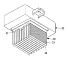
- the heat radiating section 30 has a base 31 and a plurality of fins 32. As shown in FIG.
- the heat radiating portion 30 is made of a metal (for example, an aluminum alloy) with excellent heat conductivity.
- the base 31 is a portion of the heat radiating section 30 that is in thermal contact with the heat generating section (power element). As a result, the heat generated by the heat generating portion is transmitted to the heat radiating portion 30 .
- the base 31 has an installation surface 31a.
- the installation surface 31a is a surface along the flow direction of the air flowing through the flow path C. As shown in FIG.
- the installation surface 31a has a raised central portion in the width direction in a cross section perpendicular to the air flow direction (see FIG. 5).
- the bulge at the central portion is not limited to the stepped shape as shown in FIG. 5, and may be mountain-shaped.
- a plurality of fins 32 are provided on the installation surface 31a.
- Each fin 32 is a thin plate-like portion that extends along the direction of air flow and is erected from the installation surface 31a in a direction orthogonal to the direction of air flow.
- the installation surface 31a and the fins 32 are arranged in the flow path C (inside the casing 10).
- the air flowing through the flow path C takes heat from the heat radiating section 30, and as a result, the heat generating section is cooled.
- a plurality of ridges 33 are formed on the side surfaces of the fins 32 along the air flow direction.
- Each ridge 33 is an elongated projecting portion extending along the direction of air flow so as to be parallel to the installation surface 31a.
- Each ridge 33 is formed continuously and integrally along the direction of air flow.
- the plurality of ridges 33 are provided along the direction in which the fins 32 are erected (vertical direction in FIG. 6).
- the surface area of the fins 32 can be increased and the heat dissipation efficiency of the heat dissipation portion 30 can be improved.
- the existence of the ridges 33 makes it difficult for the air flowing on the installation surface 31a to move in the direction in which the fins 32 are erected, and the ridges 33 act as flow path resistance to slightly reduce the flow velocity of the air. It is possible to suppress separation of the air flowing above from the installation surface 31a. In particular, it is possible to suppress separation from the rear half portion (the rear half portion in the air flow direction) of the installation surface 31a.
- the ridges 33 may be formed over the entire height of the fins 32 .
- the surface area of the fins 32 can be increased by making the most of the height dimension of the fins 32 (the dimension along the erecting direction).
- the protrusions 33 may be omitted from a portion of the fin 32 on the side of the tip 32a and a portion of the fin 32 on the side of the base 32b.
- the ridges 33 are a part of the flow path C as a whole that can be a flow resistance, so by omitting the ridges 33 in a part of the area in the standing direction, the pressure loss caused by the fins 32 can be reduced. can be made
- the ridges 33 may be formed only on the base end 32b side of the half of the fins 32 in the direction in which the fins 32 are erected.
- the heat radiating section 30 configured as described above is manufactured by, for example, extrusion molding. As a result, a large number of heat radiating portions 30 having the same cross-sectional shape can be manufactured.
- This embodiment has the following effects.
- a plurality of ridges 33 formed along the flow direction are provided on the surface of the fins 32 over the erecting direction of the fins 32, so that the surface area of the fins 32 is increased and the heat dissipation efficiency of the heat dissipation part 30 is improved. can be improved.
- the existence of the ridges 33 makes it difficult for the air flowing on the installation surface 31a to move in the direction in which the fins 32 are erected, and the ridges 33 act as flow path resistance to slightly reduce the flow velocity of the air. It is possible to suppress separation of the air flowing above from the installation surface 31a. Therefore, since the air flow is maintained on the installation surface 31a (that is, there is no region where the flow velocity becomes zero or the region where the air flows backward), the air conditioner is installed on and from the installation surface 31a. A decrease in heat radiation efficiency in the fins 32 can be suppressed.
- the surface area of the fins 32 can be maximized.
- the ridges 33 are formed only on half of the fins 32 on the base end 32b side in the erecting direction of the fins 32, separation of air on the base end 32b side is suppressed, while air separation is suppressed on the tip 32a side. Pressure loss due to the protrusions 33 can be suppressed.
- a vehicle air conditioner according to an aspect of the present disclosure has an air intake (11) and an air discharge port (12), and a flow path (C) communicating between the air intake and the air discharge port.
- a casing (10) formed with a fan (41) housed in the casing and generating an air flow from the air intake port to the air discharge port via the flow path;
- a heat-generating portion and a heat-radiating portion (30) are provided, wherein the heat-radiating portion is thermally connected to the heat-generating portion and is arranged in a base (31) having an installation surface (31a) and the flow path.
- a plurality of plate-like fins (32) extending along the direction of air flow and erected from the installation surface in a direction perpendicular to the direction of flow;
- a plurality of ridges (33) formed along the flow direction are provided over the erecting direction of the fins.
- the casing, the fan, the heat-generating section, and the heat-radiating section are provided. It has a plurality of plate-shaped fins that are arranged in the air passage and extend along the air flow direction and stand upright from the installation surface in a direction perpendicular to the air flow direction. Since a plurality of ridges formed along the fins are provided in the standing direction of the fins, it is possible to increase the surface area of the fins and improve the heat dissipation efficiency of the heat dissipation portion.
- the heat generating part is, for example, a power element that controls the rotation of the fan.
- the plurality of ridges are formed over the entire area in the erecting direction of the fins.
- the plurality of ridges are formed over the entire area of the fins in the erecting direction, so that the surface area of the fins can be maximized.
- the plurality of ridges are formed on a portion of the fin on the tip end side and a portion of the fin on the base end side in the erecting direction of the fin. Absent.
- the pressure loss in the portion on the distal end side and the portion on the proximal end side is reduced. can be suppressed. As a result, the pressure loss in the flow path as a whole can be suppressed.
- the plurality of ridges are formed only on the proximal half of the fin in the standing direction of the fin.
- the plurality of ridges are formed only on the proximal half portion of the fin in the direction in which the fin is erected, so separation of the air on the proximal end side is suppressed. At the same time, it is possible to suppress the pressure loss due to the protrusions on the tip side.
- the extending direction of the plurality of protrusions is parallel to the installation surface.
- the heat radiating section can be manufactured by extrusion molding.
Landscapes
- Engineering & Computer Science (AREA)
- Physics & Mathematics (AREA)
- Thermal Sciences (AREA)
- Mechanical Engineering (AREA)
- General Engineering & Computer Science (AREA)
- Air-Conditioning For Vehicles (AREA)
- Cooling Or The Like Of Electrical Apparatus (AREA)
Abstract
Description
すなわち、本開示の一態様に係る車両用空調装置は、空気取入口及び空気吐出口を有し、前記空気取入口と前記空気吐出口とを連通する流路が形成されたケーシングと、前記ケーシングに収容され、前記空気取入口から前記流路を介して前記空気吐出口へ至る空気の流れを生成するファンと、前記ケーシングの外部に設けられた発熱部と、放熱部と、を備え、前記放熱部は、該発熱部と熱的に接続され、設置面を有するベースと、前記流路に配置され、空気の流れ方向に沿って延在するとともに前記設置面から前記流れ方向に直交する方向に立設された板状の複数のフィンを有し、複数の前記フィンの表面には、前記流れ方向に沿って形成された突条が前記フィンの立設方向に亘って複数設けられている。
また、ケーシング10は、空気取入口11と空気吐出口12と連通する流路Cを画定している。
ファン41は、空気取入口11側のケーシング10に収容されている。
ファン41を駆動するモータの回転は、パワー素子(例えばMOS-FET)によって制御される。
パワー素子とは、電力制御用の半導体素子であり、通電時には発熱する。このため、車両用空調装置1を運転する際には発熱部としてのパワー素子を放熱部30で冷却している。
このとき、ユニット20は、壁部13の外部(ケーシング10の外部)に配置されている。
放熱部30は、伝熱性に優れた金属(例えばアルミ合金)によって形成されている。
設置面31aは、流路Cを流れる空気の流れ方向に沿う面である。
設置面31aは、空気の流れ方向に直交する断面(図5参照)において幅方向の中央部が凸状に盛り上がっている。なお、中央部の盛り上がりは、図5のような階段状に限らず山型状であってもよい。
各フィン32は、空気の流れ方向に沿って延在するとともに空気の流れ方向に直交する方向において設置面31aから立設する薄い板状の部分である。
これによって、流路Cを流れる空気が放熱部30から熱を奪うので、結果として発熱部が冷却されることになる。
各突条33は、空気の流れ方向に沿って連続的、一体的に形成されている。また、複数の突条33は、フィン32の立設方向(図6において上下方向)に亘って設けられている。
また、突条33の存在によって設置面31a上を流れる空気がフィン32の立設方向に移動しにくくなることや突条33が流路抵抗となり空気の流速がやや低下することで、設置面31a上を流れる空気が設置面31aからはく離することを抑制できる。特に、設置面31aにおける後半部分(空気の流れ方向の後半部分)からのはく離を抑制することができる。
突条33は、フィン32の高さ方向の全域に亘って形成されていてもよい。
また、フィン32の先端32a側の一部及び基端32b側の一部で突条33を省略してもよい。
また、図8に示すように、フィン32の立設方向においてフィン32の半分よりも基端32b側の部分にのみ突条33を形成してもよい。
フィン32の表面には、流れ方向に沿って形成された突条33がフィン32の立設方向に亘って複数設けられているので、フィン32の表面積を増大させて放熱部30での放熱効率を向上させることができる。
このため、設置面31a上では空気の流れが維持されるので(すなわち、流速がゼロになる領域、或いは空気が逆流する領域が存在しないので)、設置面31a上及び設置面31aから立設するフィン32における放熱効率の低下を抑制できる。
すなわち、本開示の一態様に係る車両用空調装置は、空気取入口(11)及び空気吐出口(12)を有し、前記空気取入口と前記空気吐出口とを連通する流路(C)が形成されたケーシング(10)と、前記ケーシングに収容され、前記空気取入口から前記流路を介して前記空気吐出口へ至る空気の流れを生成するファン(41)と、前記ケーシングの外部に設けられた発熱部と、放熱部(30)と、を備え、前記放熱部は、発熱部と熱的に接続され、設置面(31a)を有するベース(31)と、前記流路に配置され、空気の流れ方向に沿って延在するとともに前記設置面から前記流れ方向に直交する方向に立設された板状の複数のフィン(32)を有し、複数の前記フィンの表面には、前記流れ方向に沿って形成された突条(33)が前記フィンの立設方向に亘って複数設けられている。
また、突条の存在によって設置面上を流れる空気がフィンの立設方向に移動しにくくなることや突条が流路抵抗となり空気の流速がやや低下することで、設置面上を流れる空気が設置面からはく離することを抑制できる。このため、設置面上では空気の流れが維持されるので、設置面上及び設置面から立設するフィンにおける放熱効率の低下を抑制できる。
ここで、発熱部とは、例えばファンの回転を制御するパワー素子である。
10 ケーシング
11 空気取入口
12 空気吐出口
13 壁部
20 ユニット(発熱部を含むユニット)
30 放熱部
31 ベース
31a 設置面
32 フィン
32a 先端
32b 基端
33 突条
41 ファン
Claims (5)
- 空気取入口及び空気吐出口を有し、前記空気取入口と前記空気吐出口とを連通する流路が形成されたケーシングと、
前記ケーシングに収容され、前記空気取入口から前記流路を介して前記空気吐出口へ至る空気の流れを生成するファンと、
前記ケーシングの外部に設けられた発熱部と、
放熱部と、
を備え、
前記放熱部は、
該発熱部と熱的に接続され、設置面を有するベースと、
前記流路に配置され、空気の流れ方向に沿って延在するとともに前記設置面から前記流れ方向に直交する方向に立設された板状の複数のフィンを有し、
複数の前記フィンの表面には、前記流れ方向に沿って形成された突条が前記フィンの立設方向に亘って複数設けられている車両用空調装置。 - 複数の前記突条は、前記フィンの立設方向の全域に亘って形成されている請求項1に記載の車両用空調装置。
- 複数の前記突条は、前記フィンの立設方向において、前記フィンの先端側の一部及び基端側の一部には形成されていない請求項1に記載の車両用空調装置。
- 複数の前記突条は、前記フィンの立設方向において、前記フィンの基端側半分の部分にのみ形成されている請求項1に記載の車両用空調装置。
- 複数の前記突条の延在方向は、前記設置面と平行とされている請求項1から4のいずれかに記載の車両用空調装置。
Priority Applications (1)
| Application Number | Priority Date | Filing Date | Title |
|---|---|---|---|
| EP22837333.8A EP4349623A4 (en) | 2021-07-05 | 2022-05-10 | VEHICLE AIR CONDITIONING SYSTEM |
Applications Claiming Priority (2)
| Application Number | Priority Date | Filing Date | Title |
|---|---|---|---|
| JP2021111529A JP2023008178A (ja) | 2021-07-05 | 2021-07-05 | 車両用空調装置 |
| JP2021-111529 | 2021-07-05 |
Publications (1)
| Publication Number | Publication Date |
|---|---|
| WO2023281912A1 true WO2023281912A1 (ja) | 2023-01-12 |
Family
ID=84801457
Family Applications (1)
| Application Number | Title | Priority Date | Filing Date |
|---|---|---|---|
| PCT/JP2022/019780 Ceased WO2023281912A1 (ja) | 2021-07-05 | 2022-05-10 | 車両用空調装置 |
Country Status (3)
| Country | Link |
|---|---|
| EP (1) | EP4349623A4 (ja) |
| JP (1) | JP2023008178A (ja) |
| WO (1) | WO2023281912A1 (ja) |
Citations (4)
| Publication number | Priority date | Publication date | Assignee | Title |
|---|---|---|---|---|
| JP2004144460A (ja) * | 2002-08-29 | 2004-05-20 | Denso Corp | 熱交換器 |
| JP2004271168A (ja) * | 2003-02-18 | 2004-09-30 | Sanyo Electric Co Ltd | 空気調和機の室外機 |
| JP2012158247A (ja) * | 2011-01-31 | 2012-08-23 | Toyota Motor Corp | 車両用空調装置 |
| JP2020179769A (ja) | 2019-04-25 | 2020-11-05 | 三菱重工サーマルシステムズ株式会社 | 車両用空気調和装置 |
Family Cites Families (4)
| Publication number | Priority date | Publication date | Assignee | Title |
|---|---|---|---|---|
| DE102009037259B4 (de) * | 2009-08-12 | 2012-04-19 | Semikron Elektronik Gmbh & Co. Kg | Anordnung mit einer Kühleinrichtung und einem Leistungshalbleitermodul |
| CN201986328U (zh) * | 2011-03-07 | 2011-09-21 | 上海逸航汽车零部件有限公司 | 一种用于汽车空调调速模块的散热装置 |
| CN202520596U (zh) * | 2012-02-10 | 2012-11-07 | 南京飞洋汽车电子有限责任公司 | 改进的汽车空调鼓风机调速模块 |
| FR3077771B1 (fr) * | 2018-02-09 | 2020-01-17 | Valeo Systemes Thermiques | Module de commande de pulseur et installation de chauffage et/ou ventilation et/ou climatisation correspondante |
-
2021
- 2021-07-05 JP JP2021111529A patent/JP2023008178A/ja active Pending
-
2022
- 2022-05-10 EP EP22837333.8A patent/EP4349623A4/en not_active Withdrawn
- 2022-05-10 WO PCT/JP2022/019780 patent/WO2023281912A1/ja not_active Ceased
Patent Citations (4)
| Publication number | Priority date | Publication date | Assignee | Title |
|---|---|---|---|---|
| JP2004144460A (ja) * | 2002-08-29 | 2004-05-20 | Denso Corp | 熱交換器 |
| JP2004271168A (ja) * | 2003-02-18 | 2004-09-30 | Sanyo Electric Co Ltd | 空気調和機の室外機 |
| JP2012158247A (ja) * | 2011-01-31 | 2012-08-23 | Toyota Motor Corp | 車両用空調装置 |
| JP2020179769A (ja) | 2019-04-25 | 2020-11-05 | 三菱重工サーマルシステムズ株式会社 | 車両用空気調和装置 |
Non-Patent Citations (1)
| Title |
|---|
| See also references of EP4349623A4 |
Also Published As
| Publication number | Publication date |
|---|---|
| JP2023008178A (ja) | 2023-01-19 |
| EP4349623A1 (en) | 2024-04-10 |
| EP4349623A4 (en) | 2024-11-20 |
Similar Documents
| Publication | Publication Date | Title |
|---|---|---|
| JP4639648B2 (ja) | インバータ装置 | |
| JP2008207645A (ja) | 車両用空調装置 | |
| CN110758061A (zh) | Ptc加热器 | |
| JP4156082B2 (ja) | 空気調和機の室外ユニット | |
| US20240381595A1 (en) | Power electronics cooling loop for refrigerant compressor | |
| WO2023281912A1 (ja) | 車両用空調装置 | |
| CN115507455B (zh) | 空调室外机和空调 | |
| JP4462877B2 (ja) | ルーバー付きヒートシンク | |
| US20210317999A1 (en) | Outdoor unit and air conditioner | |
| US20030168208A1 (en) | Electronic component cooling apparatus | |
| JP5794866B2 (ja) | 空気調和装置の室内機 | |
| US11976827B2 (en) | Outdoor unit and air conditioner | |
| CN101151585A (zh) | 冷却装置 | |
| CN215637643U (zh) | 电控盒、空调室外机和空调器 | |
| JP2005243925A (ja) | 冷却モジュール | |
| US11788738B2 (en) | Outdoor unit and air conditioner | |
| JP2002013836A (ja) | 熱交換装置 | |
| JP2021124264A (ja) | 室外機および空気調和機 | |
| JPH1134634A (ja) | ブロアファン制御アンプ | |
| KR102898854B1 (ko) | 차량용 난방장치 및 이를 구비한 차량용 공조장치 | |
| CN111397423B (zh) | 散热器及空调 | |
| CN119325211A (zh) | 一种散热装置及散热装置的控制方法 | |
| JP2008186956A (ja) | 車載用電子制御装置の放熱装置 | |
| JP2002353679A (ja) | 制御盤の冷却装置 | |
| JPH0722324U (ja) | 空気調和機の室外機 |
Legal Events
| Date | Code | Title | Description |
|---|---|---|---|
| 121 | Ep: the epo has been informed by wipo that ep was designated in this application |
Ref document number: 22837333 Country of ref document: EP Kind code of ref document: A1 |
|
| WWE | Wipo information: entry into national phase |
Ref document number: 2022837333 Country of ref document: EP Ref document number: 2401000001 Country of ref document: TH |
|
| NENP | Non-entry into the national phase |
Ref country code: DE |
|
| ENP | Entry into the national phase |
Ref document number: 2022837333 Country of ref document: EP Effective date: 20240102 |
|
| WWW | Wipo information: withdrawn in national office |
Ref document number: 2022837333 Country of ref document: EP |