WO2023282086A1 - 風力発電タワー及び風力発電タワーの構築方法 - Google Patents
風力発電タワー及び風力発電タワーの構築方法 Download PDFInfo
- Publication number
- WO2023282086A1 WO2023282086A1 PCT/JP2022/025143 JP2022025143W WO2023282086A1 WO 2023282086 A1 WO2023282086 A1 WO 2023282086A1 JP 2022025143 W JP2022025143 W JP 2022025143W WO 2023282086 A1 WO2023282086 A1 WO 2023282086A1
- Authority
- WO
- WIPO (PCT)
- Prior art keywords
- tower
- legs
- wind power
- wind turbine
- wind
- Prior art date
- Legal status (The legal status is an assumption and is not a legal conclusion. Google has not performed a legal analysis and makes no representation as to the accuracy of the status listed.)
- Ceased
Links
Images



Classifications
-
- E—FIXED CONSTRUCTIONS
- E04—BUILDING
- E04H—BUILDINGS OR LIKE STRUCTURES FOR PARTICULAR PURPOSES; SWIMMING OR SPLASH BATHS OR POOLS; MASTS; FENCING; TENTS OR CANOPIES, IN GENERAL
- E04H12/00—Towers; Masts or poles; Chimney stacks; Water-towers; Methods of erecting such structures
- E04H12/34—Arrangements for erecting or lowering towers, masts, poles, chimney stacks, or the like
-
- E—FIXED CONSTRUCTIONS
- E04—BUILDING
- E04H—BUILDINGS OR LIKE STRUCTURES FOR PARTICULAR PURPOSES; SWIMMING OR SPLASH BATHS OR POOLS; MASTS; FENCING; TENTS OR CANOPIES, IN GENERAL
- E04H12/00—Towers; Masts or poles; Chimney stacks; Water-towers; Methods of erecting such structures
- E04H12/34—Arrangements for erecting or lowering towers, masts, poles, chimney stacks, or the like
- E04H12/344—Arrangements for lifting tower sections for placing additional sections under them
-
- F—MECHANICAL ENGINEERING; LIGHTING; HEATING; WEAPONS; BLASTING
- F03—MACHINES OR ENGINES FOR LIQUIDS; WIND, SPRING, OR WEIGHT MOTORS; PRODUCING MECHANICAL POWER OR A REACTIVE PROPULSIVE THRUST, NOT OTHERWISE PROVIDED FOR
- F03D—WIND MOTORS
- F03D13/00—Assembly, mounting or commissioning of wind motors; Arrangements specially adapted for transporting wind motor components
- F03D13/20—Arrangements for mounting or supporting wind motors; Masts or towers for wind motors
- F03D13/201—Towers
-
- E—FIXED CONSTRUCTIONS
- E04—BUILDING
- E04H—BUILDINGS OR LIKE STRUCTURES FOR PARTICULAR PURPOSES; SWIMMING OR SPLASH BATHS OR POOLS; MASTS; FENCING; TENTS OR CANOPIES, IN GENERAL
- E04H12/00—Towers; Masts or poles; Chimney stacks; Water-towers; Methods of erecting such structures
- E04H12/02—Structures made of specified materials
- E04H12/08—Structures made of specified materials of metal
-
- E—FIXED CONSTRUCTIONS
- E04—BUILDING
- E04H—BUILDINGS OR LIKE STRUCTURES FOR PARTICULAR PURPOSES; SWIMMING OR SPLASH BATHS OR POOLS; MASTS; FENCING; TENTS OR CANOPIES, IN GENERAL
- E04H12/00—Towers; Masts or poles; Chimney stacks; Water-towers; Methods of erecting such structures
- E04H12/02—Structures made of specified materials
- E04H12/12—Structures made of specified materials of concrete or other stone-like material, with or without internal or external reinforcements, e.g. with metal coverings, with permanent form elements
-
- F—MECHANICAL ENGINEERING; LIGHTING; HEATING; WEAPONS; BLASTING
- F03—MACHINES OR ENGINES FOR LIQUIDS; WIND, SPRING, OR WEIGHT MOTORS; PRODUCING MECHANICAL POWER OR A REACTIVE PROPULSIVE THRUST, NOT OTHERWISE PROVIDED FOR
- F03D—WIND MOTORS
- F03D13/00—Assembly, mounting or commissioning of wind motors; Arrangements specially adapted for transporting wind motor components
- F03D13/10—Assembly of wind motors; Arrangements for erecting wind motors
- F03D13/112—Assembly of wind motors; Arrangements for erecting wind motors of towers; of masts
-
- F—MECHANICAL ENGINEERING; LIGHTING; HEATING; WEAPONS; BLASTING
- F05—INDEXING SCHEMES RELATING TO ENGINES OR PUMPS IN VARIOUS SUBCLASSES OF CLASSES F01-F04
- F05B—INDEXING SCHEME RELATING TO WIND, SPRING, WEIGHT, INERTIA OR LIKE MOTORS, TO MACHINES OR ENGINES FOR LIQUIDS COVERED BY SUBCLASSES F03B, F03D AND F03G
- F05B2240/00—Components
- F05B2240/90—Mounting on supporting structures or systems
- F05B2240/91—Mounting on supporting structures or systems on a stationary structure
- F05B2240/912—Mounting on supporting structures or systems on a stationary structure on a tower
-
- Y—GENERAL TAGGING OF NEW TECHNOLOGICAL DEVELOPMENTS; GENERAL TAGGING OF CROSS-SECTIONAL TECHNOLOGIES SPANNING OVER SEVERAL SECTIONS OF THE IPC; TECHNICAL SUBJECTS COVERED BY FORMER USPC CROSS-REFERENCE ART COLLECTIONS [XRACs] AND DIGESTS
- Y02—TECHNOLOGIES OR APPLICATIONS FOR MITIGATION OR ADAPTATION AGAINST CLIMATE CHANGE
- Y02E—REDUCTION OF GREENHOUSE GAS [GHG] EMISSIONS, RELATED TO ENERGY GENERATION, TRANSMISSION OR DISTRIBUTION
- Y02E10/00—Energy generation through renewable energy sources
- Y02E10/70—Wind energy
- Y02E10/72—Wind turbines with rotation axis in wind direction
-
- Y—GENERAL TAGGING OF NEW TECHNOLOGICAL DEVELOPMENTS; GENERAL TAGGING OF CROSS-SECTIONAL TECHNOLOGIES SPANNING OVER SEVERAL SECTIONS OF THE IPC; TECHNICAL SUBJECTS COVERED BY FORMER USPC CROSS-REFERENCE ART COLLECTIONS [XRACs] AND DIGESTS
- Y02—TECHNOLOGIES OR APPLICATIONS FOR MITIGATION OR ADAPTATION AGAINST CLIMATE CHANGE
- Y02E—REDUCTION OF GREENHOUSE GAS [GHG] EMISSIONS, RELATED TO ENERGY GENERATION, TRANSMISSION OR DISTRIBUTION
- Y02E10/00—Energy generation through renewable energy sources
- Y02E10/70—Wind energy
- Y02E10/728—Onshore wind turbines
Definitions
- the present invention relates to a wind turbine tower for supporting a wind turbine in the sky and a method for constructing a wind turbine tower.
- a wind power generator is equipped with a wind power generator equipped with a rotor and nacelle, and a wind power generator tower for supporting the wind power generator in the sky. be done.
- the higher the position the higher the wind speed. Therefore, there is an increasing need to make the wind turbine tower taller in order to improve power generation efficiency.
- a hybrid tower for wind power generation is known as a wind power generation tower to meet such needs (Patent Document 1).
- This hybrid tower for wind power generation has a highly rigid concrete structure at the bottom of the tower and a steel structure with excellent workability at the top of the tower.
- the lower part of the tower is made of prestressed concrete
- the upper part of the tower is made of a steel cylinder that is spliced together. This configuration is said to enable wind towers with a height of over 70m (eg 100m).
- the construction method of this hybrid tower consists of a concrete cylinder casting process at the bottom of the tower, a prestress introduction process at the bottom of the tower, and a steel cylinder installation process at the top of the tower.
- the concrete cylinder placing step an inner formwork and an outer formwork are assembled on the footing, and concrete is poured into the formwork to sequentially construct concrete cylinders vertically.
- the prestress introducing step a PC steel material is placed between a fixing part placed at the top of a concrete cylinder that has reached a predetermined length and a fixing device placed in a footing, and the PC steel material is tensioned, A prestress is introduced into the concrete tube.
- the steel cylinder installation process a steel cylinder is vertically spliced onto the concrete cylinder.
- the wind turbine towers are constructed in order from the bottom. Therefore, a crane that is higher than the wind turbine tower is required in order to locate the steel cylinder at the top of the tower or to locate the wind turbine that is to be mounted thereon. The height of the wind tower is therefore limited by the height of the crane.
- one aspect of the present invention is a wind turbine tower (5) for supporting a wind turbine (4) in the sky, comprising a foundation (8) tilted toward each other.
- a tower lower part (11) having at least three legs (14) made of hollow concrete erected on the upper part of the tower (11), and a tower middle part (12) arranged in the center of the at least three legs (14) in plan view ), said tower middle part (12) made of cone-shaped hollow concrete having a lower end (12a) supported by said legs (14) and an upper end (12b) narrower than said lower end (12a);
- a tower upper part (13) projecting upward from the tower middle part (12) and supporting the wind generator (4), the lower half part (13) supported by the upper end (12b) of the tower middle part (12) 13a) and said tower top (13) made of steel pipe with an exposed body (13b).
- concrete construction includes reinforced concrete construction, fiber reinforced concrete construction, reinforced steel frame construction, prestressed concrete construction, precast concrete construction, cast-in-place concrete construction, and the like.
- the lower part and the middle part of the tower are made of hollow concrete, the required rigidity of the wind power tower can be easily secured, so the height of the wind power tower can be increased.
- the lower part of the tower has at least three legs made of hollow concrete, the amount of concrete in the lower part of the tower can be reduced, and the increase in the weight of the wind power generation tower and the increase in the size of the foundation can be suppressed.
- the upper part of the tower is made of a steel pipe, it is possible to easily secure the bending performance necessary for the wind turbine tower.
- the tower middle part (12) has at least three flat surfaces (17) equally spaced in the circumferential direction on the outer peripheral surface of the lower end (12a), and the leg parts (14) each of has a flat joint surface (18) facing said mid-tower (12) and is clamped by tendons (20) with said joint surface (18) facing said corresponding flat surface (17) It may be fastened to the tower middle part (12).
- the central part of the tower and the legs can be securely fastened.
- a filler (19) is filled between the joint surface (18) of the leg (14) and the flat surface (17) of the central tower (12).
- the wind turbine tower (5) preferably further comprises a support member (15) that rotatably supports the leg (14) on the foundation (8).
- the legs can be rotated, it is easy to connect the legs and the central part of the tower.
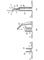
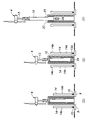
- an aspect of the present invention is a method for constructing a wind turbine tower (5) according to the above aspect, wherein the area (21) to be surrounded by the legs (14) includes: The steps of constructing a tower upper part (13) and said tower middle part (12) (Fig. 4(B)-(C)) and supporting said wind generator (4) on said tower upper part (13) (Fig. 4 (B)), constructing at least three said legs (14) upwards and substantially vertically (Fig. 5(D)), and said tower top supporting said wind generator (4) ( 13) and the step of lifting the middle part of the tower (12) to a predetermined sky position (FIG. 5(F)), and rotating the at least three legs (14) on the foundation (8).
- the upper part (14b) of the leg part (14) is brought into contact with the lower end (12a) of the middle part (12) of the tower (12) in the sky position (FIG. 6(G)); , connecting each of said upper parts (14b) of said legs (14) to said lower ends (12a) of said tower middle part (12) and allowing said tower lower part (11) to support said tower middle part (12); FIG. 6(H)).
- the wind power generator is supported on the upper part of the tower before the upper part and the central part of the tower are lifted up to a predetermined upper position. Therefore, it is not necessary to use a crane that is taller than the wind turbine tower in order to place the tower top and the wind turbine generator. Therefore, the wind tower can be constructed without being restricted by the height of the crane.
- the construction method includes a balance weight ( 24) (Fig. 5(E)) and after coupling each of the upper parts (14b) of said legs (14) to said lower ends (12a) of said tower middle part (12), said tower middle part (12) ) and removing the balance weight (24) from the lower end (12a) of (Fig. 6(I)).
- the nacelle (3) of the wind turbine generator (4) is arranged.
- the tower upper part (13) and the tower middle part (12) may be constructed while jacking up in order from the top.
- the work of arranging the nacelle and the work of connecting the nacelle and the upper part of the tower can be performed at a low position. Therefore, there is no need to prepare a large crane with a large lifting height, and construction costs can be reduced.
- FIG. 1 is a side view of the wind turbine generator 1 according to the embodiment.
- the wind turbine generator 1 includes a wind turbine generator 4 having a rotor 2 and a nacelle 3, and a wind turbine tower 5 for supporting the wind turbine generator 4 in the sky.
- the wind turbine generator 1 of the present embodiment is configured as an onshore wind power generation facility constructed on land.
- the wind power generator 1 may be configured as a bottom-mounted offshore wind power generation facility constructed on the sea.
- the rotor 2 includes a hub 6 having a horizontal axis and a plurality of blades 7 radially extending from the hub 6 and arranged around the axis of the hub 6 .
- the rotor 2 rotates around the axis of the hub 6 when the blades 7 receive the wind.
- the nacelle 3 supports the rotor 2 rotatably around its axis.
- the nacelle 3 internally includes a gearbox to which the rotor 2 is connected on the input side, and a generator connected to the output side of the gearbox. When the rotor 2 rotates, the nacelle 3 accelerates the rotation with the gearbox and generates electricity with the generator.
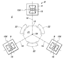
- FIG. 2 is a cross-sectional view taken along line II-II in FIG.
- the wind turbine generator 1 is built on a foundation 8 (support structure) constructed on the ground G.
- Base 8 includes three footings 9 .
- the three footings 9 are arranged at positions radially evenly spaced from the center 5X of the wind turbine tower 5 in plan view and at equal intervals (120° intervals) around the center 5X. These three footings 9 may be connected to each other by an underground beam (not shown).
- the wind turbine tower 5 comprises a lower tower portion 11 supported by a foundation 8, a middle tower portion 12 supported by the lower tower portion 11, and an upper tower portion 13 supported by the middle tower portion 12 and supporting the wind generator 4.
- the tower lower part 11 has three legs 14 made of hollow concrete erected on the footing 9 so as to be inclined toward each other.
- the tower lower part 11 has a tripod structure with three legs 14 .
- Each leg portion 14 has a leg body portion 14a inclined with respect to the vertical line, and a leg upper portion 14b extending upward from the upper end of the leg body portion 14a and extending substantially vertically.
- a support member 15 is provided at the lower end of each leg portion 14 .
- the support member 15 is embedded in concrete and configured as an extension portion that extends the leg portion 14 downward.
- the bearing member 15 may be exposed rather than embedded in concrete.
- the support member 15 is a rotary support member that rotatably supports the leg portion 14 on the foundation 8 before being embedded in concrete.
- the support member 15 has a rotating shaft 15X extending in the horizontal direction.
- the bearing member 15 is arranged so that the rotation axis 15X is perpendicular to the imaginary line 16 extending from the center 5X of the wind turbine tower 5 toward the bearing member 15. As shown in FIG. In this manner, the leg 14 is supported by the support member 15 so as to be rotatable about the rotation shaft 15X, so that the upper portion can be tilted in a direction to approach the center 5X of the wind turbine tower 5 and move away from it.
- the tower middle part 12 is arranged in the center of the three legs 14 in plan view.
- the central part 12 of the tower is made of cone-shaped hollow concrete and has a lower end 12a supported by the legs 14 and an upper end 12b thinner than the lower end 12a.
- FIG. 2 the outer contour of the lower end 12a of the central part 12 of the tower projected vertically downward from above is shown by imaginary lines.
- FIG. 3 is a cross-sectional view along III-III in FIG.
- the central tower portion 12 has three flat surfaces 17 formed at equal intervals in the circumferential direction on the outer peripheral surface of the lower end 12a.
- Each of the legs 14 has a flat mating surface 18 facing the middle tower 12 on the upper leg 14b.
- the leg upper part 14b is arranged so that the joint surface 18 faces the corresponding flat surface 17.
- a filler material 19 is filled between the joint surface 18 of the leg portion 14 and the flat surface 17 of the central tower portion 12 .
- the filler 19 is a filling material that hardens over time and has fluidity, and may be non-shrink mortar, for example.
- the leg upper part 14b is fastened to the tower middle part 12 by tendons 20 with the joint surface 18 facing the corresponding flat surface 17 via the filler material 19 .
- the tendon 20 may be, for example, a plurality of post tension bars (PT bars) made of steel bars.
- the tower upper part 13 is made of a steel pipe and is provided so as to protrude upward from the tower central part 12 .
- the tower upper part 13 has a lower half part 13 a supported by the upper end 12 b of the tower middle part 12 and a body part 13 b exposed between the tower middle part 12 and the nacelle 3 .
- the lower half portion 13a of the tower upper portion 13 refers to a portion surrounded by the upper end 12b of the tower middle portion 12, and extends vertically within the tower middle portion 12 over a predetermined height.
- the upper tower portion 13 is rigidly connected to the middle tower portion 12 by connecting the lower half portion 13 a to the upper end 12 b of the middle tower portion 12 .
- the main body portion 13b of the tower upper portion 13 extends upward over a predetermined height from the tower central portion 12, and is the portion of the wind power generation tower 5 that has the lowest rigidity and is flexible.
- the main body portion 13b of the tower upper portion 13 functions as a heat radiating portion that radiates the heat of the nacelle 3 to the atmosphere by being exposed.
- the wind power tower 5 is configured as described above. As a result, it is possible to increase the height of the wind power tower 5 while suppressing an increase in the weight of the wind power tower 5 and an increase in the size of the foundation 8 .
- the tower lower part 11 and the tower middle part 12 are made of hollow concrete, the rigidity required for the wind power generation tower 5 can be easily secured, so the height of the wind power generation tower 5 can be increased.
- the tower lower part 11 has three legs 14 made of hollow concrete, the amount of concrete in the tower lower part 11 is reduced, and the increase in the weight of the wind power generation tower 5 and the increase in the size of the foundation 8 are suppressed.
- the lower tower part 11 consists of three legs 14, it is easy to connect the legs 14 to the middle part 12 of the tower so as to support the load evenly.
- the tower upper part 13 is made of a steel pipe, it is easy to secure the bending performance required for the wind power generation tower 5 .
- the wind turbine tower 5 of the present embodiment may be configured with the dimensions exemplified below, although not limited thereto.
- the height of the wind power tower 5 (from the upper surface of the foundation 8 to the lower surface of the nacelle 3) is preferably 100 m or more, for example 220 m.
- the height of the tower lower part 11 and the tower middle part 12 (from the upper surface of the foundation 8 to the upper end 12b of the tower middle part 12) is preferably 90 m or more, for example 200 m.
- the exposed body portion 13b of the tower upper portion 13 may have a height of about 10 to 25 m.
- the height of the tower upper part 13 may be about 15 to 50 m.
- the height of the middle part 12 of the tower may be about 60 to 140 m, and the height of the lower end 12a of the middle part 12 of the tower supported by the legs 14 may be about 10 to 30 m.
- the height of the tower lower part 11 may be about 50 to 120 m.
- the height of the script body portion 14a may be about 40 to 100 m, and the height of the leg upper portion 14b may be about 10 to 30 m.
- the diameter of the lower end 12a of the central tower 12 may be about 7.5 to 17.5 m, and the diameter of the upper end 12b of the central tower 12 may be smaller than the diameter of the lower end 12a and may be about 5 to 12 m.
- the radius of the tower lower part 11 (from the center 5X of the wind turbine tower 5 to the center of the lower end of each leg 14) may be about 12 to 30 m.
- the rotor 2 is not limited to this, its radius may be about 50 to 120 m, for example.
- the tower middle part 12 has three flat surfaces 17 formed at equal intervals in the circumferential direction on the outer peripheral surface of the lower end 12a.
- Each of the legs 14 has a flat joint surface 18 facing the middle tower 12 and is fastened by a tendon 20 with the joint surface 18 facing the corresponding flat surface 17 . Thereby, the tower middle part 12 and the leg part 14 are reliably fastened.
- a filler 19 is filled between the joint surface 18 of the leg portion 14 and the flat surface 17 of the central tower portion 12 . Therefore, gaps caused by manufacturing errors or construction errors are filled with the filler 19, and the leg portion 14 and the tower central portion 12 are fastened in a state of being in close contact.
- the wind turbine tower 5 includes support members 15 that rotatably support the legs 14 on the foundation 8 . This allows the legs 14 to rotate, and facilitates coupling between the legs 14 and the tower middle section 12 . This point will be explained later.
- FIG. 4A workers first build a foundation 8 including three footings 9 at predetermined positions on the ground G.
- a lift-up platform 22 for constructing the tower upper part 13 and the tower middle part 12 is assembled in the area 21 (see FIG. 2) to be surrounded by the legs 14.
- the lift-up platform 22 is arranged on the outer peripheral side of the lower end 12a of the tower central part 12 having the largest cross-sectional dimension.
- the lift-up frame 22 is assembled in the lower part and extended upward at appropriate timing. At least the upper portion of the lift-up platform 22 is assembled at a position not overlapping the three legs 14 around the center 5X of the wind turbine tower 5 (in the circumferential direction).
- a crane 23 is used to place the nacelle 3 on the lift-up frame 22 and erect the tower upper part 13 on the ground G. Either the arrangement of the nacelle 3 or the arrangement of the tower upper part 13 may be performed first. After disposing the nacelle 3 and the tower upper part 13 , the lower surface of the nacelle 3 is coupled to the upper end of the tower upper part 13 so that the tower upper part 13 supports the nacelle 3 .
- the middle part 12 of the tower is constructed while being jacked up from the top so as to be coupled to the lower half part 13a of the upper part 13 of the tower.
- the rotor 2 including the blades 7 is attached to the nacelle 3.
- the tower upper part 13 and the tower middle part 12 are jacked up in order from the top below the nacelle 3.
- the operation of arranging the nacelle 3 and the operation of connecting the nacelle 3 and the tower upper part 13 can be performed at a low position. Therefore, there is no need to prepare a large crane with a large lifting height, and construction costs are reduced.
- the three legs 14 are directed upward and constructed substantially vertically.
- the support member 15 is arranged and fixed on the footing 9 .
- the support member 15 is preferably fixed by a lock member at an angle such that the upper surface becomes horizontal.
- the leg body portion 14a of the leg portion 14 is constructed vertically on the support member 15.
- the legs 14 may be constructed, for example, by sequentially stacking a plurality of hollow precast concrete members using a crane 23 and joining them together by the tension of the PC tendons. In other embodiments, legs 14 may be constructed of cast-in-place concrete.
- the balance weight 24 is attached to the lower end 12a of the central tower 12 as shown in FIG. 5(E).
- the tower upper part 13 and the tower middle part 12 that support the wind power generator 4 are lifted up to a predetermined sky position using the lift-up frame 22 .
- the predetermined aerial position is the position in which the completed wind tower 5 shown in FIG. 1 is located.
- each of the upper leg portions 14b is connected to the lower end 12a of the central tower portion 12 using tendons 20 to support the central tower portion 12 on the lower tower portion 11.
- the unconstructed portion is constructed on the constructed portion of the leg 14 .
- a filler 19 is filled between the joint surface 18 of the leg portion 14 and the flat surface 17 of the central tower portion 12 .
- the upper leg portions 14b of the leg portions 14 are attached to the tower by tendons 20 while the joint surfaces 18 of the legs 14 are opposed to the corresponding flat surfaces 17 of the middle tower portion 12 via the filler material 19. It is fastened to the lower end 12a of the middle part 12.
- the balance weight 24 is removed from the lower end 12a of the central part 12 of the tower. Also, the lift-up frame 22 is dismantled. In this embodiment, concrete is poured into the lower end of the leg portion 14, and the support member 15 is embedded in the concrete. Thereby, the wind turbine generator 1 shown in FIG. 1 is constructed.
- the wind turbine tower 5 can be constructed without being restricted by the height of the crane.
- the present invention is not limited to the above-described embodiments and modifications, and can be widely modified.
- the lower tower portion 11 has three legs 14 in the above embodiment, it may have four or more legs 14 .
- the specific configuration, arrangement, quantity, angle, material, procedure, etc. of each member and part can be changed as appropriate within the scope of the present invention.
- not all of the components shown in the above embodiments are essential, and can be selected as appropriate.
- Wind turbine generator 2 Rotor 3 : Nacelle 4 : Wind generator 5 : Wind turbine tower 8 : Foundation 9 : Footing 11 : Tower lower part 12 : Tower middle part 12a : Lower end 12b : Upper end 13 : Tower upper part 13a : Lower half part 13b: main body portion 14: leg portion 14a: leg body portion 14b: upper leg portion 15: support member 17: flat surface 18: joint surface 19: filler material 20: tension material 21: area 24: balance weight
Landscapes
- Engineering & Computer Science (AREA)
- Architecture (AREA)
- Civil Engineering (AREA)
- Chemical & Material Sciences (AREA)
- Life Sciences & Earth Sciences (AREA)
- Structural Engineering (AREA)
- Materials Engineering (AREA)
- Wood Science & Technology (AREA)
- Sustainable Development (AREA)
- Sustainable Energy (AREA)
- Combustion & Propulsion (AREA)
- Mechanical Engineering (AREA)
- General Engineering & Computer Science (AREA)
- Wind Motors (AREA)
Abstract
Description
2 :ローター
3 :ナセル
4 :風力発電機
5 :風力発電タワー
8 :基礎
9 :フーチング
11 :タワー下部
12 :タワー中部
12a :下端
12b :上端
13 :タワー上部
13a :下半部
13b :本体部
14 :脚部
14a :脚本体部
14b :脚上部
15 :支承部材
17 :平坦面
18 :接合面
19 :充填材
20 :緊張材
21 :領域
24 :バランス錘
Claims (7)
- 風力発電機を上空に支持するための風力発電タワーであって、
互いに近付く向きに傾斜するように基礎上に立設された中空コンクリート製の少なくとも3本の脚部を有するタワー下部と、
平面視で少なくとも3本の前記脚部の中央に配置されるタワー中部であって、前記脚部に支持される下端と前記下端よりも細い上端とを有するコーン形状の中空コンクリート製の該タワー中部と、
前記タワー中部から上方へ突出し、前記風力発電機を支持するタワー上部であって、前記タワー中部の前記上端に支持される下半部と露出した本体部とを有する鋼管からなる該タワー上部とを備える風力発電タワー。 - 前記タワー中部は、前記下端の外周面にて周方向に等間隔に形成された少なくとも3つの平坦面を有し、
前記脚部のそれぞれは、前記タワー中部に向く平坦な接合面を有し、前記接合面を対応する前記平坦面に対向させた状態で緊張材によって前記タワー中部に締結されている請求項1に記載の風力発電タワー。 - 前記脚部の前記接合面と前記タワー中部の前記平坦面との間には充填材が充填されている請求項2に記載の風力発電タワー。
- 前記脚部を前記基礎上にて回動可能に支承する支承部材を更に備える請求項1~3のいずれか1項に記載の風力発電タワー。
- 請求項1~4のいずれか1項に記載の風力発電タワーの構築方法であって、
前記脚部によって囲まれるべき領域にて、前記タワー上部及び前記タワー中部を構築するステップと、
前記タワー上部に前記風力発電機を支持させるステップと、
少なくとも3本の前記脚部を上方に向けて略鉛直に構築するステップと、
前記風力発電機を支持する前記タワー上部及び前記タワー中部を所定の上空位置にリフトアップするステップと、
前記基礎上にて少なくとも3本の前記脚部を回動させて互いに近づく向きに傾斜させ、前記脚部の上部を前記上空位置にある前記タワー中部の前記下端に当接させるステップと、
前記脚部の前記上部のそれぞれを前記タワー中部の前記下端に結合し、前記タワー下部に前記タワー中部を支持させるステップとを含む風力発電タワーの構築方法。 - 前記タワー上部及び前記タワー中部を前記上空位置にリフトアップする前に、前記タワー中部の前記下端にバランス錘を取り付けるステップと、
前記脚部の前記上部のそれぞれを前記タワー中部の前記下端に結合した後に、前記タワー中部の前記下端から前記バランス錘を取り外すステップとを更に含む請求項5に記載の風力発電タワーの構築方法。 - 前記タワー上部及び前記タワー中部を構築するステップにおいて、前記風力発電機のナセルを配置し、前記ナセルの下方にて、前記タワー上部及び前記タワー中部を上から順にジャッキアップしながら構築する請求項6に記載の風力発電タワーの構築方法。
Priority Applications (3)
| Application Number | Priority Date | Filing Date | Title |
|---|---|---|---|
| JP2023533530A JP7826313B2 (ja) | 2021-07-08 | 2022-06-23 | 風力発電タワー及び風力発電タワーの構築方法 |
| US18/569,820 US12577800B2 (en) | 2021-07-08 | 2022-06-23 | Wind power generation tower and construction method of wind power generation tower |
| EP22837503.6A EP4368832A4 (en) | 2021-07-08 | 2022-06-23 | WIND POWER GENERATION TOWER AND METHOD FOR CONSTRUCTING A WIND POWER GENERATION TOWER |
Applications Claiming Priority (2)
| Application Number | Priority Date | Filing Date | Title |
|---|---|---|---|
| JP2021-113270 | 2021-07-08 | ||
| JP2021113270 | 2021-07-08 |
Publications (1)
| Publication Number | Publication Date |
|---|---|
| WO2023282086A1 true WO2023282086A1 (ja) | 2023-01-12 |
Family
ID=84801028
Family Applications (1)
| Application Number | Title | Priority Date | Filing Date |
|---|---|---|---|
| PCT/JP2022/025143 Ceased WO2023282086A1 (ja) | 2021-07-08 | 2022-06-23 | 風力発電タワー及び風力発電タワーの構築方法 |
Country Status (5)
| Country | Link |
|---|---|
| US (1) | US12577800B2 (ja) |
| EP (1) | EP4368832A4 (ja) |
| JP (1) | JP7826313B2 (ja) |
| TW (1) | TWI814472B (ja) |
| WO (1) | WO2023282086A1 (ja) |
Cited By (1)
| Publication number | Priority date | Publication date | Assignee | Title |
|---|---|---|---|---|
| JP2025094866A (ja) * | 2023-12-13 | 2025-06-25 | 株式会社高橋監理 | 浮体式洋上風力発電所 |
Citations (3)
| Publication number | Priority date | Publication date | Assignee | Title |
|---|---|---|---|---|
| JP2009057713A (ja) | 2007-08-30 | 2009-03-19 | Kyushu Electric Power Co Inc | 風力発電用ハイブリッドタワー及びその施工法 |
| WO2013083802A2 (en) * | 2011-12-07 | 2013-06-13 | Dong Energy Wind Power A/S | Support structure for wind turbine and method of mounting such support structure |
| JP2017516945A (ja) * | 2014-05-27 | 2017-06-22 | エステイコ・ソシエダッド・アノニマ・プロフェシオナルEsteyco S.A.P. | 風力タービン用浮体式下部構造およびそれの設置方法 |
Family Cites Families (11)
| Publication number | Priority date | Publication date | Assignee | Title |
|---|---|---|---|---|
| US861244A (en) * | 1905-05-25 | 1907-07-30 | Archbold Brady Company | Leg foundation for skeleton towers. |
| US1647925A (en) * | 1925-04-25 | 1927-11-01 | May John Walter | Anchor footing for steel towers |
| ES2319709B8 (es) * | 2006-11-29 | 2014-05-26 | Prefabricaciones Y Contratas, S.A. | Estructura de soporte para dispositivos aerogeneradores |
| US8734705B2 (en) | 2008-06-13 | 2014-05-27 | Tindall Corporation | Method for fabrication of structures used in construction of tower base supports |
| ES2595231T3 (es) * | 2010-04-06 | 2016-12-28 | Soletanche Freyssinet | Método de construcción de torre híbrida para un generador eólico |
| US8240955B2 (en) * | 2010-06-29 | 2012-08-14 | General Electric Company | Tower segments and method for off-shore wind turbines |
| US7993107B2 (en) * | 2010-10-25 | 2011-08-09 | General Electric Company | Onshore wind turbine with tower support system |
| WO2013144558A1 (en) * | 2012-03-24 | 2013-10-03 | Matthew Bleasdale | Structures for offshore installations |
| EP2834435A1 (en) * | 2012-04-04 | 2015-02-11 | Forida Development A/S | Wind turbine comprising a tower part of an ultra-high performance fiber reinforced composite |
| DE102012106772A1 (de) * | 2012-07-25 | 2014-01-30 | Thyssenkrupp Steel Europe Ag | Modularer Turm einer Windkraftanlage |
| CN112009634A (zh) * | 2013-04-30 | 2020-12-01 | Acs服务通信与能源公司 | 在近海设施中的可潜的主动式支撑结构 |
-
2022
- 2022-06-23 EP EP22837503.6A patent/EP4368832A4/en active Pending
- 2022-06-23 US US18/569,820 patent/US12577800B2/en active Active
- 2022-06-23 WO PCT/JP2022/025143 patent/WO2023282086A1/ja not_active Ceased
- 2022-06-23 JP JP2023533530A patent/JP7826313B2/ja active Active
- 2022-07-06 TW TW111125348A patent/TWI814472B/zh active
Patent Citations (3)
| Publication number | Priority date | Publication date | Assignee | Title |
|---|---|---|---|---|
| JP2009057713A (ja) | 2007-08-30 | 2009-03-19 | Kyushu Electric Power Co Inc | 風力発電用ハイブリッドタワー及びその施工法 |
| WO2013083802A2 (en) * | 2011-12-07 | 2013-06-13 | Dong Energy Wind Power A/S | Support structure for wind turbine and method of mounting such support structure |
| JP2017516945A (ja) * | 2014-05-27 | 2017-06-22 | エステイコ・ソシエダッド・アノニマ・プロフェシオナルEsteyco S.A.P. | 風力タービン用浮体式下部構造およびそれの設置方法 |
Non-Patent Citations (1)
| Title |
|---|
| See also references of EP4368832A4 |
Cited By (2)
| Publication number | Priority date | Publication date | Assignee | Title |
|---|---|---|---|---|
| JP2025094866A (ja) * | 2023-12-13 | 2025-06-25 | 株式会社高橋監理 | 浮体式洋上風力発電所 |
| JP7842390B2 (ja) | 2023-12-13 | 2026-04-08 | 株式会社高橋監理 | 浮体式洋上風力発電所 |
Also Published As
| Publication number | Publication date |
|---|---|
| US12577800B2 (en) | 2026-03-17 |
| TW202317862A (zh) | 2023-05-01 |
| EP4368832A4 (en) | 2024-11-13 |
| JPWO2023282086A1 (ja) | 2023-01-12 |
| US20240287827A1 (en) | 2024-08-29 |
| JP7826313B2 (ja) | 2026-03-09 |
| TWI814472B (zh) | 2023-09-01 |
| EP4368832A1 (en) | 2024-05-15 |
Similar Documents
| Publication | Publication Date | Title |
|---|---|---|
| JP7433859B2 (ja) | 風力発電装置の支持構造及び風力発電装置 | |
| US20170218919A1 (en) | Wind tracing, rotational, semi-submerged raft for wind power generation and a construction method thereof | |
| US8919074B2 (en) | Telescopic tower assembly and method | |
| KR101171201B1 (ko) | 강관말뚝 기초와 조립식 구조물을 사용한 해상풍력 구조물 및 그 시공 방법 | |
| DK2570555T3 (en) | A tower base section of a wind turbine, a wind turbine and a system for mounting a tower | |
| US11365714B2 (en) | Methods for mounting or dismounting a wind turbine component of a multirotor wind turbine | |
| US20070151194A1 (en) | Lifting system and apparatus for constructing wind turbine towers | |
| EP1074663A1 (en) | A foundation for supporting a building structure, in particular for the foundation of a tower structure, a wind turbine or the like | |
| KR101318111B1 (ko) | 파력 저감형 다열 파일 하이브리드 해상풍력 지지구조물 및 그 시공 방법 | |
| AU2004238973A1 (en) | Foundation for a wind energy plant | |
| JP7313212B2 (ja) | 洋上施設用浮体構造物及びその設置構造 | |
| US20110037271A1 (en) | Wind turbine system and modular wind turbine unit therefor | |
| EP3394426A1 (en) | Methods for mounting or dismounting wind turbine components of a multirotor wind turbine | |
| KR101164227B1 (ko) | 강관말뚝 기초와 조립식 구조물을 사용한 해상풍력 구조물 | |
| WO2023282086A1 (ja) | 風力発電タワー及び風力発電タワーの構築方法 | |
| WO2013100441A1 (ko) | 강관말뚝 기초와 조립식 구조물을 사용한 해상풍력 구조물 및 그 시공 방법 | |
| CN207813829U (zh) | 海上风力发电机组整体安装下部就位系统及柔性安装系统 | |
| KR101689884B1 (ko) | 탑상 구조물의 기초 구조 | |
| DK181339B1 (en) | Method of assembly and installation of an offshore support structure for a wind turbine | |
| CA3091540C (en) | Semi-finished part for a foundation of a tower construction and methods for production thereof | |
| KR20130061457A (ko) | 해상풍력발전용 하부구조물 및 설치방법 | |
| JP7757942B2 (ja) | 風力発電装置の設置方法および風力発電システム | |
| WO2025094466A1 (ja) | 浮体式風力発電設備の構築方法 | |
| JP2001254669A (ja) | 風力発電用風車体 | |
| JP2022149531A (ja) | 塔型風力発電設備の解体におけるブレードの降ろし方法 |
Legal Events
| Date | Code | Title | Description |
|---|---|---|---|
| 121 | Ep: the epo has been informed by wipo that ep was designated in this application |
Ref document number: 22837503 Country of ref document: EP Kind code of ref document: A1 |
|
| WWE | Wipo information: entry into national phase |
Ref document number: 2023533530 Country of ref document: JP |
|
| WWE | Wipo information: entry into national phase |
Ref document number: 18569820 Country of ref document: US |
|
| WWE | Wipo information: entry into national phase |
Ref document number: 2022837503 Country of ref document: EP |
|
| NENP | Non-entry into the national phase |
Ref country code: DE |
|
| ENP | Entry into the national phase |
Ref document number: 2022837503 Country of ref document: EP Effective date: 20240208 |
|
| WWG | Wipo information: grant in national office |
Ref document number: 18569820 Country of ref document: US |