WO2023282096A1 - 物体検出装置 - Google Patents
物体検出装置 Download PDFInfo
- Publication number
- WO2023282096A1 WO2023282096A1 PCT/JP2022/025400 JP2022025400W WO2023282096A1 WO 2023282096 A1 WO2023282096 A1 WO 2023282096A1 JP 2022025400 W JP2022025400 W JP 2022025400W WO 2023282096 A1 WO2023282096 A1 WO 2023282096A1
- Authority
- WO
- WIPO (PCT)
- Prior art keywords
- value
- average value
- detection
- received
- reference value
- Prior art date
- Legal status (The legal status is an assumption and is not a legal conclusion. Google has not performed a legal analysis and makes no representation as to the accuracy of the status listed.)
- Ceased
Links
Images



Classifications
-
- G—PHYSICS
- G01—MEASURING; TESTING
- G01S—RADIO DIRECTION-FINDING; RADIO NAVIGATION; DETERMINING DISTANCE OR VELOCITY BY USE OF RADIO WAVES; LOCATING OR PRESENCE-DETECTING BY USE OF THE REFLECTION OR RERADIATION OF RADIO WAVES; ANALOGOUS ARRANGEMENTS USING OTHER WAVES
- G01S15/00—Systems using the reflection or reradiation of acoustic waves, e.g. sonar systems
- G01S15/02—Systems using the reflection or reradiation of acoustic waves, e.g. sonar systems using reflection of acoustic waves
- G01S15/50—Systems of measurement, based on relative movement of the target
- G01S15/52—Discriminating between fixed and moving objects or between objects moving at different speeds
- G01S15/523—Discriminating between fixed and moving objects or between objects moving at different speeds for presence detection
- G01S15/526—Discriminating between fixed and moving objects or between objects moving at different speeds for presence detection by comparing echos in different sonar periods
-
- G—PHYSICS
- G01—MEASURING; TESTING
- G01S—RADIO DIRECTION-FINDING; RADIO NAVIGATION; DETERMINING DISTANCE OR VELOCITY BY USE OF RADIO WAVES; LOCATING OR PRESENCE-DETECTING BY USE OF THE REFLECTION OR RERADIATION OF RADIO WAVES; ANALOGOUS ARRANGEMENTS USING OTHER WAVES
- G01S15/00—Systems using the reflection or reradiation of acoustic waves, e.g. sonar systems
- G01S15/02—Systems using the reflection or reradiation of acoustic waves, e.g. sonar systems using reflection of acoustic waves
- G01S15/06—Systems determining the position data of a target
- G01S15/08—Systems for measuring distance only
- G01S15/10—Systems for measuring distance only using transmission of interrupted, pulse-modulated waves
-
- G—PHYSICS
- G01—MEASURING; TESTING
- G01S—RADIO DIRECTION-FINDING; RADIO NAVIGATION; DETERMINING DISTANCE OR VELOCITY BY USE OF RADIO WAVES; LOCATING OR PRESENCE-DETECTING BY USE OF THE REFLECTION OR RERADIATION OF RADIO WAVES; ANALOGOUS ARRANGEMENTS USING OTHER WAVES
- G01S7/00—Details of systems according to groups G01S13/00, G01S15/00, G01S17/00
- G01S7/52—Details of systems according to groups G01S13/00, G01S15/00, G01S17/00 of systems according to group G01S15/00
- G01S7/523—Details of pulse systems
- G01S7/526—Receivers
-
- G—PHYSICS
- G01—MEASURING; TESTING
- G01S—RADIO DIRECTION-FINDING; RADIO NAVIGATION; DETERMINING DISTANCE OR VELOCITY BY USE OF RADIO WAVES; LOCATING OR PRESENCE-DETECTING BY USE OF THE REFLECTION OR RERADIATION OF RADIO WAVES; ANALOGOUS ARRANGEMENTS USING OTHER WAVES
- G01S7/00—Details of systems according to groups G01S13/00, G01S15/00, G01S17/00
- G01S7/52—Details of systems according to groups G01S13/00, G01S15/00, G01S17/00 of systems according to group G01S15/00
- G01S7/523—Details of pulse systems
- G01S7/526—Receivers
- G01S7/527—Extracting wanted echo signals
- G01S7/5273—Extracting wanted echo signals using digital techniques
-
- G—PHYSICS
- G01—MEASURING; TESTING
- G01S—RADIO DIRECTION-FINDING; RADIO NAVIGATION; DETERMINING DISTANCE OR VELOCITY BY USE OF RADIO WAVES; LOCATING OR PRESENCE-DETECTING BY USE OF THE REFLECTION OR RERADIATION OF RADIO WAVES; ANALOGOUS ARRANGEMENTS USING OTHER WAVES
- G01S13/00—Systems using the reflection or reradiation of radio waves, e.g. radar systems; Analogous systems using reflection or reradiation of waves whose nature or wavelength is irrelevant or unspecified
- G01S13/88—Radar or analogous systems specially adapted for specific applications
- G01S13/93—Radar or analogous systems specially adapted for specific applications for anti-collision purposes
- G01S13/931—Radar or analogous systems specially adapted for specific applications for anti-collision purposes of land vehicles
-
- G—PHYSICS
- G01—MEASURING; TESTING
- G01S—RADIO DIRECTION-FINDING; RADIO NAVIGATION; DETERMINING DISTANCE OR VELOCITY BY USE OF RADIO WAVES; LOCATING OR PRESENCE-DETECTING BY USE OF THE REFLECTION OR RERADIATION OF RADIO WAVES; ANALOGOUS ARRANGEMENTS USING OTHER WAVES
- G01S15/00—Systems using the reflection or reradiation of acoustic waves, e.g. sonar systems
- G01S15/88—Sonar systems specially adapted for specific applications
- G01S15/93—Sonar systems specially adapted for specific applications for anti-collision purposes
- G01S15/931—Sonar systems specially adapted for specific applications for anti-collision purposes of land vehicles
-
- G—PHYSICS
- G01—MEASURING; TESTING
- G01S—RADIO DIRECTION-FINDING; RADIO NAVIGATION; DETERMINING DISTANCE OR VELOCITY BY USE OF RADIO WAVES; LOCATING OR PRESENCE-DETECTING BY USE OF THE REFLECTION OR RERADIATION OF RADIO WAVES; ANALOGOUS ARRANGEMENTS USING OTHER WAVES
- G01S7/00—Details of systems according to groups G01S13/00, G01S15/00, G01S17/00
- G01S7/52—Details of systems according to groups G01S13/00, G01S15/00, G01S17/00 of systems according to group G01S15/00
- G01S7/523—Details of pulse systems
- G01S7/526—Receivers
- G01S7/527—Extracting wanted echo signals
Definitions
- the present disclosure relates to an object detection device.
- the TOF method is based on the difference between the timing at which a transmission wave such as an ultrasonic wave is transmitted and the timing at which a reception wave (reflected wave) generated by the reflection of the transmission wave from an object is received. This is a technique for calculating the distance to an object and the like.
- road surface clutter, etc. is detected by subtracting a moving average value of received signal values obtained in a predetermined period before and after a given received signal from the value of the received signal.
- CFAR Constant False Alarm Rate
- One of the problems of the present disclosure is to provide an object detection device that can detect objects with high accuracy using CFAR processing.
- An object detection device includes a transmission unit that transmits a transmission wave, a reception unit that receives a reception wave generated when the transmission wave is reflected by an object, and a reception wave received at a certain detection timing. Acquire the difference value between the value to be processed, which is the value of the corresponding signal to be processed, and the reference value based on the moving average value of each value of the reference signal group corresponding to the received wave received in a predetermined period before and after the detection timing a CFAR processing unit that generates information about an object based on the difference value; and a setting unit that selects a reference value that matches the detection distance corresponding to the detection timing from a plurality of reference values.
- the reference value (value to be subtracted from the value to be processed) used in CFAR processing can be optimized according to the distance. Thereby, the accuracy of object detection using CFAR processing can be improved.
- the setting unit may set the reference value such that the closer the detection distance is, the larger the reference value is.
- the setting unit selects a first reference value from a plurality of reference values when the detection distance is within a predetermined short range, and selects a plurality of reference values when the detection distance is in a middle range farther than the short range. Select a second reference value that is smaller than the first reference value from, and select a third reference value that is smaller than the second reference value from a plurality of reference values when the detection distance is in a long range that is farther than the middle range. good.
- the first reference value is the first average value which is the average value of the values of the first reference signal group corresponding to the received wave received in the first predetermined time before the detection timing, and the first reference value after the detection timing.
- the second reference value is the maximum average value that is the larger one of the second average value that is the average value of the values of the second reference signal group corresponding to the received waves received during the second predetermined time, and the second reference value is , the average value of all reference values including each value of the first reference signal group and each value of the second reference signal group, and the third reference value is the first average value and the second average value It may be the minimum average value which is the smaller value of and.
- FIG. 1 is a top view showing an example of the appearance of a vehicle equipped with a driving assistance system according to an embodiment.
- FIG. 2 is a block diagram showing an example of hardware configurations of an ECU and an object detection device according to the first embodiment.
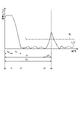
- FIG. 3 is a diagram showing an example of a distance calculation method using the TOF method.
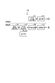
- 4 is a block diagram illustrating an example of a functional configuration of the object detection device according to the embodiment;
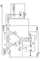
- FIG. FIG. 5 is a diagram illustrating an example of CFAR processing and reference value setting processing according to the embodiment;
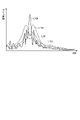
- FIG. 6 is a diagram illustrating an example of a total average value, maximum average value, and minimum average value according to the embodiment;
- FIG. 7 is a flowchart illustrating an example of reference value setting processing in the object detection device according to the embodiment;
- FIG. 1 is a top view showing an example of the appearance of a vehicle 1 equipped with a driving support system according to an embodiment.
- the driving support system exemplified below uses ultrasonic waves to detect objects (other vehicles, road obstacles, people, animals, etc.) existing around the vehicle 1, and drives the vehicle 1 based on the detection results. It is a system that performs processing to support
- the driving support system includes an ECU (Electronic Control Unit) 100 mounted inside a vehicle 1 having a pair of front wheels 3F and a pair of rear wheels 3R, and an ECU (Electronic Control Unit) 100 mounted on the exterior of the vehicle 1. and object detection devices 201-204.
- ECU Electronic Control Unit
- the object detection devices 201 to 204 are installed at different positions on the rear end portion (for example, rear bumper) of the vehicle body 2 as the exterior of the vehicle 1 .
- the hardware configurations and functions of the object detection devices 201 to 204 are the same. Therefore, hereinafter, the object detection devices 201 to 204 may be collectively referred to as the object detection device 200 for simplification.
- the installation position of the object detection device 200 is not limited to the example shown in FIG.
- the object detection device 200 may be installed, for example, on the front end portion (for example, front bumper, etc.) or the side portion of the vehicle body 2 .
- the number of object detection devices 200 is not limited to the example shown in FIG.
- FIG. 2 is a block diagram showing an example of hardware configurations of the ECU 100 and the object detection device 200 according to the first embodiment.
- the ECU 100 includes an input/output device 110, a storage device 120, and a processor .
- the input/output device 110 is an interface that enables transmission and reception of information between the ECU 100 and external devices (such as the object detection device 200).
- the storage device 120 includes main storage devices such as ROM (Read Only Memory) and RAM (Random Access Memory), and/or auxiliary storage devices such as HDD (Hard Disk Drive) and SSD (Solid State Drive).
- the processor 130 is an arithmetic processing device including a CPU (Central Processing Unit) that performs various kinds of arithmetic processing according to programs stored in the storage device 120 .
- the processor 130 performs various processes (for example, processes for realizing automatic operation, alarm output, etc.) based on various information (for example, detection results of the object detection device 200, etc.) input from the input/output device 110 .
- the object detection device 200 includes a transmitter/receiver 210 and a control section 220 .
- the transmitter/receiver 210 has a vibrator 211 such as a piezoelectric element, and the action of the vibrator 211 realizes transmission and reception of ultrasonic waves. Specifically, the transmitter/receiver 210 transmits an ultrasonic wave generated in response to the vibration of the transducer 211 as a transmission wave, and the ultrasonic wave transmitted as the transmission wave is reflected by an external object and returned. The vibration of the vibrator 211 caused by the movement is received as a received wave.
- an obstacle O installed on the road surface RS is illustrated as an object that reflects the transmitted wave from the transmitter/receiver 210 .
- FIG. 2 illustrates a configuration in which both the transmission of transmission waves and the reception of reception waves are realized by a single transceiver 210 having a single transducer 211, but the embodiment is similar to this. is not limited to For example, a configuration in which a mechanism on the transmitting side and a mechanism on the receiving side are separated, such as a configuration in which a first transducer for transmitting transmission waves and a second transducer for receiving reception waves are provided separately. may be
- the control unit 220 includes an input/output device 221 , a storage device 222 and a processor 223 .
- the input/output device 221 is an interface that enables transmission and reception of information between the control unit 220 and external devices (ECU 100, transmitter/receiver 210, etc.).
- the storage device 222 includes main storage devices such as ROM and RAM, and/or auxiliary storage devices such as HDD and SSD.
- the processor 223 is an arithmetic processing device including a CPU or the like that performs various arithmetic processing according to programs stored in the storage device 333 .
- the processor 223 performs various processes (for example, generating information about the obstacle O, etc.) based on various information (for example, detection data of the transmitter/receiver 210, etc.) input from the input/output device 221 .
- the object detection device 200 detects the distance to an object (for example, an obstacle O, etc.) using a technique called the TOF method.
- the TOF method is based on the timing at which a transmission wave was transmitted (more specifically, it began to be transmitted) and the timing at which a received wave was received (more specifically, it began to be received). This technology calculates the distance to an object based on the timing difference.
- FIG. 3 is a diagram showing an example of a distance calculation method using the TOF method.
- FIG. 3 illustrates an envelope L11 (echo information) representing temporal changes in the intensity (signal level) of ultrasonic waves transmitted and received by the transmitter/receiver 210 .
- the horizontal axis corresponds to time (TOF)
- the vertical axis corresponds to the intensity of ultrasonic waves transmitted and received by the transmitter/receiver 210 (magnitude of vibration of the transducer 211).
- An envelope L11 indicates the change over time of the strength indicating the magnitude of vibration of the vibrator 211 .
- the oscillator 211 is driven and oscillated for the time Ta from the timing t0, and the transmission of the transmission wave is completed at the timing t1.
- the vibration of the vibrator 211 due to inertia continues while attenuating. Therefore, in the graph shown in FIG. 3, the time Tb corresponds to the so-called reverberation time.
- the envelope L11 reaches a peak when the magnitude of vibration of the vibrator 211 exceeds the detection threshold Th at timing t4, which is the time Tp after the timing t0 at which transmission of the transmission wave is started.
- This detection threshold Th is determined by whether the vibration of the vibrator 211 is caused by receiving a reflected wave from an obstacle O (another vehicle, a structure, a pedestrian, etc.), or by an object other than the obstacle O (for example, the road surface RS etc.).
- the detection threshold Th is shown here as a constant value, the detection threshold Th may be a variable value that changes according to the situation.
- a vibration having a peak equal to or greater than the detection threshold Th can be considered to be caused by reception of a reflected wave from the obstacle O.
- the envelope L11 in this example indicates that the vibration of the vibrator 211 is attenuated after timing t4. Therefore, the timing t4 corresponds to the timing when the reception of the reflected wave from the obstacle O is completed, in other words, the timing when the transmission wave last transmitted at the timing t1 returns as a reflected wave.
- timing t3 which is the starting point of the peak at timing t4 is the timing at which reception of the reflected wave from the obstacle O starts. corresponds to the timing of returning as Therefore, the time ⁇ T between the timing t3 and the timing t4 is equal to the time Ta as the transmission time of the transmission wave.
- the timing t0 when the transmission wave starts to be transmitted can be easily identified as the timing when the object detection device 200 starts operating, and the time Ta as the transmission time of the transmission wave is predetermined by setting or the like. Therefore, the distance from the transmission/reception source to the obstacle O can be obtained by specifying the timing t4 at which the intensity of the reflected wave reaches a peak equal to or higher than the detection threshold Th.
- FIG. 4 is a block diagram showing an example of the functional configuration of the object detection device 200 according to the embodiment.
- the object detection apparatus 200 includes a transmission section 411 , a transmission control section 412 , a reception section 421 , a preprocessing section 422 , a CFAR processing section 423 , a setting section 424 and a detection processing section 425 .
- These functional components 411, 412, 421 to 425 can be realized, for example, by cooperation of hardware components of the object detection device 200 illustrated in FIG. 2 and software components such as programs.
- the configuration on the transmitting side and the configuration on the receiving side are separated, but such an illustrated aspect is for convenience of explanation only.
- both transmission of transmission waves and reception of reception waves are realized by a single transmitter/receiver 210 having a single transducer 211 .
- a configuration in which the configuration on the transmission side and the configuration on the reception side are separated is also applicable.
- the transmission unit 411 transmits transmission waves to the outside by vibrating the oscillator 211 described above.
- the transmission unit 411 includes, for example, a circuit that generates a carrier wave, a circuit that generates a pulse signal corresponding to identification information to be given to the carrier wave, a multiplier that modulates the carrier wave according to the pulse signal, a multiplier It can be configured using an amplifier or the like that amplifies the transmission signal output from the device.
- the transmission control unit 412 controls transmission of transmission waves.
- the transmission control unit 412 controls, for example, the transmission time, transmission interval, intensity, wavelength, frequency, etc. of transmission waves.
- the transmission control unit 412 may adjust the transmission of the transmission wave based on, for example, the detection result of the object, the state of the road surface RS, the speed of the vehicle 1, and the like.
- the reception unit 421 receives reception waves (reflected waves) generated by reflection of the transmission waves transmitted from the transmission unit 411 by an object.
- the receiving unit 421 can be configured using, for example, an AD converter or the like in addition to the transducer 211 .
- the preprocessing unit 422 performs preprocessing to generate echo information (for example, an envelope as illustrated in FIG. 3) that indicates the temporal change in the intensity of received waves.
- Preprocessing includes, for example, amplification processing for amplifying the received signal corresponding to the received wave, filtering processing for reducing noise contained in the amplified received signal, and obtaining a correlation value indicating the degree of similarity between the transmitted signal and the received signal. Correlation processing, etc., may be included.
- the CFAR processing unit 423 executes CFAR processing on the echo information generated by the preprocessing unit 422.
- the CFAR processing unit 423 generates a processing target value, which is a value of a processing target signal corresponding to a received wave received at a certain detection timing, and a group of reference signals corresponding to received waves received in a predetermined period before and after the detection timing. Get the difference value from the reference value based on the moving average value of each value.
- the CFAR processing unit 423 according to the present embodiment performs CA-CFAR (Cell Averaging Constant False Alarm Rate) processing, GO-CFAR (Greatest Of Constant False Alarm Rate) processing, and SO-CFAR (Smallest Of Constant False Alarm Rate) process.
- CA-CFAR processing includes each value of the first reference signal group corresponding to the received wave received in the first predetermined period before the detection timing, and the received wave received in the second predetermined period after the detection timing. This is a process using the average value (total average value) of all reference values including each value of the second reference signal group corresponding to , as a reference value.
- GO-CFAR processing refers to the larger of the first average value that is the average value of each value of the first reference signal group and the second average value that is the average value of each value of the second reference signal group ( maximum average value) as a reference value.
- SO-CFAR processing is processing in which the smaller value (minimum average value) of the first average value and the second average value is used as a reference value.
- the setting unit 424 executes reference value setting processing for selecting a reference value to be used in CFAR processing based on the detection distance corresponding to the detection timing from a plurality of preset reference values.
- the setting unit 424 sets (selects) the reference value so that the reference value in the CFAR process becomes larger as the detection distance is shorter. A specific example of the reference value setting process will be described later.
- the detection processing unit 425 generates information about the object based on the difference value acquired by the CFAR processing unit 423. For example, the detection processing unit 425 determines the presence or absence of an object (obstacle O), the distance to the object, etc. based on the TOF when the difference value exceeds a predetermined threshold (for example, the detection threshold Th illustrated in FIG. 3). generate the information shown.
- a predetermined threshold for example, the detection threshold Th illustrated in FIG. 3
- FIG. 5 is a diagram showing an example of CFAR processing and reference value setting processing according to the embodiment.
- a signal to be processed 501 is a received signal corresponding to a received wave received at a certain detection timing.
- a first reference signal group 502 is a reception signal group corresponding to reception waves received in the first predetermined period before the detection timing corresponding to the signal to be processed 501 .
- a second reference signal group 503 is a reception signal group corresponding to reception waves received during a second predetermined period after the detection timing corresponding to the signal to be processed 501 .
- CFAR processing section 423 generates a first average value that is the average value of each value of first reference signal group 502 and a second average value that is the average value of each value of second reference signal group 503 . and a total average value that is the average value of all reference values including each value of the first reference signal group 502 and each value of the second reference signal group 503 are calculated.
- the setting unit 424 compares the first average value and the second average value, outputs the larger one as the maximum average value, and outputs the smaller one as the minimum average value. Further, the setting unit 424 selects an average value suitable for the distance (detection distance) corresponding to the detection timing corresponding to the signal to be processed 501 from among the total average value, the maximum average value, and the minimum average value. Set the average value as the reference value. Specifically, the setting unit 424 sets the maximum average value as a reference value when the detection distance is within a predetermined short distance range, sets the total average value as the reference value, and sets the minimum average value as the reference value when the detection distance is in a predetermined long range that is farther than the middle range.
- the CFAR processing unit 423 calculates a difference value by subtracting the reference value set by the setting unit 424 from the processing target value.
- the detection processing unit 425 generates a measurement result indicating the distance to the obstacle O based on the comparison result between the difference value calculated as described above and a threshold value (for example, the detection threshold value Th illustrated in FIG. 3).
- the specific numerical values of the short range, middle range, and long range should not be particularly limited, for example, the short range is less than 2 m, the middle range is 2 m or more and less than 4 m, and the long range is It can be set to 4m or more.
- FIG. 6 is a diagram showing an example of the total average value, maximum average value, and minimum average value according to the embodiment.
- an envelope L700 indicating temporal changes in the signal level (strength) of the received wave
- an overall average value line L701 indicating temporal changes in the total average value
- a maximum average value indicating temporal changes in the maximum average value
- the relationship between the value line L702 and the minimum average value line L703 indicating the temporal change of the minimum average value is illustrated.
- the maximum average value is larger than the overall average value
- the minimum average value is smaller than the overall average value.
- FIG. 7 is a flowchart showing an example of reference value setting processing in the object detection device 200 according to the embodiment.
- the CFAR processing unit 423 extracts the value of the processing target signal 501 from the echo information generated by the preprocessing unit 422. A value (see FIG. 5) is obtained (S102). After that, the CFAR processing unit 423 calculates the total average value, the first average value, and the second average value (S103), and the setting unit 424 selects the larger one of the first average value and the second average value as the maximum average value. value, and the smaller one is determined as the minimum average value (S104).
- the setting unit 424 determines whether or not the detection distance is within the short distance range (S105), and if the detection distance is within the short distance range (S105: Yes), sets the reference value to the maximum average value. (S106). If the detected distance is not within the short range (S105: No), the setting unit 424 determines whether the detected distance is within the middle range (S107). If the detected distance is within the middle distance range (S107: Yes), the setting unit 424 sets the reference value to the total average value (S108). If the detected distance is not within the middle range (S107: No), the setting unit 424 determines whether the detected distance is within the long range (S109).
- the setting unit 424 sets the reference value to the minimum average value (S110). If the detected distance is not within the long distance range (S109: No), the setting unit 424 sets the reference value to a predetermined default value (S111). A difference value is calculated by CFAR processing using the reference value set in this way, and information about an object (such as an obstacle O) is generated based on the difference value.
- the reference value used for CFAR processing can be appropriately set according to the detection distance. This makes it possible to perform highly accurate object detection using CFAR processing.
- a program that causes a computer (the processors 223 and 130 in the above embodiment) to execute processing for realizing the functions described above is stored as a file in an installable or executable format on a CD-ROM, a CD-R, or a memory. It may be stored in a computer-readable storage medium such as a card, DVD (Digital Versatile Disk), flexible disk (FD), etc., and provided as a computer program product. Alternatively, the program may be stored on a computer connected to a network such as the Internet, and provided by being downloaded via the network. Also, the program may be provided or distributed via a network such as the Internet.
Landscapes
- Engineering & Computer Science (AREA)
- Radar, Positioning & Navigation (AREA)
- Remote Sensing (AREA)
- Physics & Mathematics (AREA)
- Computer Networks & Wireless Communication (AREA)
- General Physics & Mathematics (AREA)
- Acoustics & Sound (AREA)
- Radar Systems Or Details Thereof (AREA)
Abstract
Description
Claims (4)
- 送信波を送信する送信部と、
前記送信波が物体に反射されることにより生じる受信波を受信する受信部と、
ある検出タイミングで受信された前記受信波に対応する処理対象信号の値である処理対象値と、前記検出タイミングの前後の所定期間に受信された前記受信波に対応する参照信号群の各値の移動平均値に基づく基準値との差分値を取得するCFAR処理部と、
前記差分値に基づいて前記物体に関する情報を生成する検出処理部と、
予め設定された複数の前記基準値から前記検出タイミングに対応する検出距離に適合する前記基準値を選択する設定部と、
を備える物体検出装置。 - 前記設定部は、前記検出距離が近いほど前記基準値が大きくなるように前記基準値を設定する、
請求項1に記載の物体検出装置。 - 前記設定部は、前記検出距離が所定の近距離範囲にある場合に複数の前記基準値から第1基準値を選択し、前記検出距離が前記近距離範囲より遠い中距離範囲にある場合に複数の前記基準値から前記第1基準値より小さい第2基準値を選択し、前記検出距離が前記中距離範囲より遠い遠距離範囲にある場合に複数の前記基準値から前記第2基準値より小さい第3基準値を選択する、
請求項2に記載の物体検出装置。 - 前記第1基準値は、前記検出タイミングより前の第1所定時間に受信された前記受信波に対応する第1参照信号群の各値の平均値である第1平均値と、前記検出タイミングより後の第2所定時間に受信された前記受信波に対応する第2参照信号群の各値の平均値である第2平均値とのうち大きい方の値である最大平均値であり、
前記第2基準値は、前記第1参照信号群の各値と前記第2参照信号群の各値とを含む全参照値の平均値である全平均値であり、
前記第3基準値は、前記第1平均値と前記第2平均値とのうち小さい方の値である最小平均値である、
請求項3に記載の物体検出装置。
Priority Applications (4)
| Application Number | Priority Date | Filing Date | Title |
|---|---|---|---|
| JP2023533537A JP7597222B2 (ja) | 2021-07-06 | 2022-06-24 | 物体検出装置 |
| CN202280042184.0A CN117480404A (zh) | 2021-07-06 | 2022-06-24 | 物体检测装置 |
| EP22837513.5A EP4369035A4 (en) | 2021-07-06 | 2022-06-24 | OBJECT DETECTION DEVICE |
| US18/289,083 US20240210557A1 (en) | 2021-07-06 | 2022-06-24 | Object detection device |
Applications Claiming Priority (2)
| Application Number | Priority Date | Filing Date | Title |
|---|---|---|---|
| JP2021112222 | 2021-07-06 | ||
| JP2021-112222 | 2021-07-06 |
Publications (1)
| Publication Number | Publication Date |
|---|---|
| WO2023282096A1 true WO2023282096A1 (ja) | 2023-01-12 |
Family
ID=84801050
Family Applications (1)
| Application Number | Title | Priority Date | Filing Date |
|---|---|---|---|
| PCT/JP2022/025400 Ceased WO2023282096A1 (ja) | 2021-07-06 | 2022-06-24 | 物体検出装置 |
Country Status (5)
| Country | Link |
|---|---|
| US (1) | US20240210557A1 (ja) |
| EP (1) | EP4369035A4 (ja) |
| JP (1) | JP7597222B2 (ja) |
| CN (1) | CN117480404A (ja) |
| WO (1) | WO2023282096A1 (ja) |
Cited By (2)
| Publication number | Priority date | Publication date | Assignee | Title |
|---|---|---|---|---|
| WO2025074779A1 (ja) * | 2023-10-02 | 2025-04-10 | 株式会社アイシン | 物体検出装置 |
| WO2025074778A1 (ja) * | 2023-10-02 | 2025-04-10 | 株式会社アイシン | 物体検出装置 |
Citations (7)
| Publication number | Priority date | Publication date | Assignee | Title |
|---|---|---|---|---|
| JPH0579487U (ja) * | 1992-03-27 | 1993-10-29 | 三菱電機株式会社 | レーダ信号処理装置 |
| JPH10148671A (ja) * | 1996-11-20 | 1998-06-02 | Nec Corp | クラッタ分離方法及びこれを用いたクラッタ分離システム |
| JP2006292597A (ja) | 2005-04-13 | 2006-10-26 | Nec Corp | レーダ信号処理装置及びそれに用いるcfar処理方法 |
| JP2008170287A (ja) * | 2007-01-12 | 2008-07-24 | Japan Radio Co Ltd | レーダ装置 |
| KR20120010457A (ko) * | 2010-07-26 | 2012-02-03 | 재단법인대구경북과학기술원 | 계산량을 향상시킨 순차통계 일정 오경보율 검파방법 |
| JP2014174007A (ja) * | 2013-03-08 | 2014-09-22 | Japan Radio Co Ltd | レーダ装置 |
| CN105699949A (zh) * | 2015-12-29 | 2016-06-22 | 北京经纬恒润科技有限公司 | 一种目标检测方法及装置 |
Family Cites Families (2)
| Publication number | Priority date | Publication date | Assignee | Title |
|---|---|---|---|---|
| KR102557840B1 (ko) * | 2018-04-02 | 2023-07-20 | 현대모비스 주식회사 | 주차보조시스템 및 이의 초음파센서 감지성능 향상 방법 |
| JP7322541B2 (ja) * | 2019-06-21 | 2023-08-08 | 株式会社アイシン | 物体検出装置 |
-
2022
- 2022-06-24 EP EP22837513.5A patent/EP4369035A4/en active Pending
- 2022-06-24 WO PCT/JP2022/025400 patent/WO2023282096A1/ja not_active Ceased
- 2022-06-24 US US18/289,083 patent/US20240210557A1/en active Pending
- 2022-06-24 JP JP2023533537A patent/JP7597222B2/ja active Active
- 2022-06-24 CN CN202280042184.0A patent/CN117480404A/zh active Pending
Patent Citations (7)
| Publication number | Priority date | Publication date | Assignee | Title |
|---|---|---|---|---|
| JPH0579487U (ja) * | 1992-03-27 | 1993-10-29 | 三菱電機株式会社 | レーダ信号処理装置 |
| JPH10148671A (ja) * | 1996-11-20 | 1998-06-02 | Nec Corp | クラッタ分離方法及びこれを用いたクラッタ分離システム |
| JP2006292597A (ja) | 2005-04-13 | 2006-10-26 | Nec Corp | レーダ信号処理装置及びそれに用いるcfar処理方法 |
| JP2008170287A (ja) * | 2007-01-12 | 2008-07-24 | Japan Radio Co Ltd | レーダ装置 |
| KR20120010457A (ko) * | 2010-07-26 | 2012-02-03 | 재단법인대구경북과학기술원 | 계산량을 향상시킨 순차통계 일정 오경보율 검파방법 |
| JP2014174007A (ja) * | 2013-03-08 | 2014-09-22 | Japan Radio Co Ltd | レーダ装置 |
| CN105699949A (zh) * | 2015-12-29 | 2016-06-22 | 北京经纬恒润科技有限公司 | 一种目标检测方法及装置 |
Non-Patent Citations (1)
| Title |
|---|
| See also references of EP4369035A4 |
Cited By (2)
| Publication number | Priority date | Publication date | Assignee | Title |
|---|---|---|---|---|
| WO2025074779A1 (ja) * | 2023-10-02 | 2025-04-10 | 株式会社アイシン | 物体検出装置 |
| WO2025074778A1 (ja) * | 2023-10-02 | 2025-04-10 | 株式会社アイシン | 物体検出装置 |
Also Published As
| Publication number | Publication date |
|---|---|
| EP4369035A4 (en) | 2024-11-06 |
| EP4369035A1 (en) | 2024-05-15 |
| JPWO2023282096A1 (ja) | 2023-01-12 |
| CN117480404A (zh) | 2024-01-30 |
| US20240210557A1 (en) | 2024-06-27 |
| JP7597222B2 (ja) | 2024-12-10 |
Similar Documents
| Publication | Publication Date | Title |
|---|---|---|
| CN111198373A (zh) | 距离检测装置以及物体检测装置 | |
| JP7597222B2 (ja) | 物体検出装置 | |
| US11698456B2 (en) | Object detection system | |
| CN115598628A (zh) | 物体检测系统以及物体检测装置 | |
| US20210302571A1 (en) | Object detection system | |
| JP7501673B2 (ja) | 物体検出装置 | |
| US11719815B2 (en) | Object detection device | |
| JP7456248B2 (ja) | 物体検出装置、および物体検出システム | |
| WO2022239470A1 (ja) | 物体検出装置 | |
| US11994583B2 (en) | Object detection device | |
| JP7581886B2 (ja) | 物体検出装置 | |
| JP7606610B2 (ja) | 物体検出装置 | |
| JP7547853B2 (ja) | 物体検出装置 | |
| WO2025074779A1 (ja) | 物体検出装置 | |
| WO2025074778A1 (ja) | 物体検出装置 | |
| JP2025121307A (ja) | 物体検出装置 | |
| CN117280244A (zh) | 物体检测装置 | |
| JP2025121308A (ja) | 物体検出装置 | |
| WO2025169808A1 (ja) | 物体検出装置 | |
| JP2025118145A (ja) | 物体検出装置 | |
| JP2025062323A (ja) | 物体検出装置 | |
| JP2025119931A (ja) | 物体検出装置 |
Legal Events
| Date | Code | Title | Description |
|---|---|---|---|
| 121 | Ep: the epo has been informed by wipo that ep was designated in this application |
Ref document number: 22837513 Country of ref document: EP Kind code of ref document: A1 |
|
| WWE | Wipo information: entry into national phase |
Ref document number: 2023533537 Country of ref document: JP |
|
| WWE | Wipo information: entry into national phase |
Ref document number: 18289083 Country of ref document: US |
|
| WWE | Wipo information: entry into national phase |
Ref document number: 202280042184.0 Country of ref document: CN |
|
| WWE | Wipo information: entry into national phase |
Ref document number: 2022837513 Country of ref document: EP |
|
| NENP | Non-entry into the national phase |
Ref country code: DE |
|
| ENP | Entry into the national phase |
Ref document number: 2022837513 Country of ref document: EP Effective date: 20240206 |