WO2023282307A1 - 回転電機用の冷却部材、回転電機、回転電機用の冷却部材の製造方法 - Google Patents
回転電機用の冷却部材、回転電機、回転電機用の冷却部材の製造方法 Download PDFInfo
- Publication number
- WO2023282307A1 WO2023282307A1 PCT/JP2022/026888 JP2022026888W WO2023282307A1 WO 2023282307 A1 WO2023282307 A1 WO 2023282307A1 JP 2022026888 W JP2022026888 W JP 2022026888W WO 2023282307 A1 WO2023282307 A1 WO 2023282307A1
- Authority
- WO
- WIPO (PCT)
- Prior art keywords
- core
- axial
- cooling water
- coolant
- cooling member
- Prior art date
- Legal status (The legal status is an assumption and is not a legal conclusion. Google has not performed a legal analysis and makes no representation as to the accuracy of the status listed.)
- Ceased
Links
Images


Classifications
-
- B—PERFORMING OPERATIONS; TRANSPORTING
- B22—CASTING; POWDER METALLURGY
- B22C—FOUNDRY MOULDING
- B22C9/00—Moulds or cores; Moulding processes
- B22C9/22—Moulds for peculiarly-shaped castings
- B22C9/24—Moulds for peculiarly-shaped castings for hollow articles
-
- H—ELECTRICITY
- H02—GENERATION; CONVERSION OR DISTRIBUTION OF ELECTRIC POWER
- H02K—DYNAMO-ELECTRIC MACHINES
- H02K5/00—Casings; Enclosures; Supports
- H02K5/04—Casings or enclosures characterised by the shape, form or construction thereof
- H02K5/20—Casings or enclosures characterised by the shape, form or construction thereof with channels or ducts for flow of cooling medium
- H02K5/203—Casings or enclosures characterised by the shape, form or construction thereof with channels or ducts for flow of cooling medium specially adapted for liquids, e.g. cooling jackets
-
- H—ELECTRICITY
- H02—GENERATION; CONVERSION OR DISTRIBUTION OF ELECTRIC POWER
- H02K—DYNAMO-ELECTRIC MACHINES
- H02K15/00—Processes or apparatus specially adapted for manufacturing, assembling, maintaining or repairing of dynamo-electric machines
- H02K15/14—Casings; Enclosures; Supports
-
- H—ELECTRICITY
- H02—GENERATION; CONVERSION OR DISTRIBUTION OF ELECTRIC POWER
- H02K—DYNAMO-ELECTRIC MACHINES
- H02K9/00—Arrangements for cooling or ventilating
- H02K9/19—Arrangements for cooling or ventilating for machines with closed casing and closed-circuit cooling using a liquid cooling medium, e.g. oil
Definitions
- the present disclosure relates to a cooling member for a rotating electrical machine, a rotating electrical machine, and a method for manufacturing the cooling member for the rotating electrical machine.
- a channel structure is known in which a radial column portion is provided between a radially inner cylindrical wall portion and a radially outer cylindrical wall portion.
- the flow path structure having a plurality of pillars is advantageous in that the outer peripheral surface of the pillars is in contact with the refrigerant path, so that the surface area capable of heat exchange can be efficiently increased.
- forming each pillar in an arrangement that does not cause unevenness in the flow of the refrigerant is effective from the viewpoint of uniforming the cooling performance at each position in the refrigerant path. useful. For example, since each pillar is erected perpendicularly to the flow of the refrigerant, the flow is obstructed. The flow of the refrigerant tends to be uneven.
- the columns in the refrigerant passage in an arrangement that reduces the bias in the flow of the refrigerant so as to satisfy the manufacturing requirements.
- the collapsible core is molded to have a radial through hole for forming the column portion.
- an object of the present disclosure is to reduce unevenness in the flow of coolant while satisfying manufacturing requirements in a flow channel structure having a plurality of pillars.
- a cooling member for a rotating electric machine comprising: a first portion forming a coolant inflow hole; a second portion forming a coolant outlet hole; a third portion forming a refrigerant passage that communicates between the refrigerant inflow hole and the refrigerant outflow hole without communicating with the outside;
- the third portion includes a plurality of first columnar portions each erected in a first direction perpendicular to the flow of the coolant and a plurality of protrusions each protruding in the first direction in the coolant path.
- a cooling member is provided in which the coolant is in contact with the surfaces of the plurality of first column portions and the surfaces of the protrusions exposed to the coolant path.
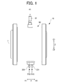
- FIG. 1 is a front view schematically showing the appearance of a rotating electric machine according to an embodiment
- FIG. FIG. 2 is a side view (plan view viewed in the axial direction) schematically showing a portion of the rotating electric machine
- FIG. 3 is a cross-sectional view schematically showing a part of the rotating electrical machine when cut along a plane passing through the rotating shaft of the rotating electrical machine
- FIG. 4 is an explanatory diagram of a cooling water passage, and is an enlarged view of a Q1 portion in FIG. 3
- FIG. 4 is an explanatory diagram of a case oil passage, and an enlarged view of a Q2 portion in FIG. 3
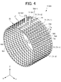
- FIG. 4 is a perspective view showing a single core related to a cooling channel
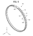
- FIG. 4 is a perspective view showing one divided body (annular core) that forms the core.
- FIG. 4 is an enlarged view of part of the annular core; 5 is a cross-sectional view along line AA in FIG. 4; FIG. 5 is a cross-sectional view along line BB of FIG. 4; FIG. 5 is a cross-sectional view along line CC of FIG. 4; FIG. It is a schematic explanatory drawing explaining an example of the shaping
- FIG. 4 is an explanatory diagram of the flow of cooling water in the cooling water passage of the embodiment, and is a top view showing a part of the outer shell of the cooling water passage.
- FIG. 4 is an explanatory diagram of the flow of cooling water in the cooling water passage of the embodiment, and is a top view showing a part of the outer shell of the cooling water passage.
- FIG. 10 is a cross-sectional view along line DD of FIG. 9;
- FIG. 10 is a cross-sectional view along line EE of FIG. 9;
- FIG. 4 is an explanatory diagram of the flow of cooling water in a cooling water channel according to a comparative example, and is a top view showing a part of the outer shell of the cooling water channel. 4 is a schematic flow chart showing the flow of a stator manufacturing method; 14 is a diagram for explaining the manufacturing method shown in FIG. 13, and is a cross-sectional view schematically showing a state during the casting process.
- FIG. 1 is a front view schematically showing the appearance of a rotating electric machine 10 according to this embodiment
- FIG. 2 is a side view (plan view viewed in the axial direction) schematically showing a part of the rotating electric machine 10.
- FIG. 3 is a cross-sectional view schematically showing a part of rotating electrical machine 10 when cut along a plane passing through rotation axis I of rotating electrical machine 10 .
- the structures of the cooling water passage 95 and the case oil passage 35 are schematically illustrated, and the details will be described later with reference to FIGS. 3A, 3B, and 5 onwards.
- 3A is an enlarged view of the Q1 portion of FIG. 3.
- FIG. 3B is an enlarged view of the Q2 portion of FIG. 3.
- FIG. FIG. 4 is a perspective view showing a single core 7 related to the cooling water passage 95.
- illustration of the rotor of the rotating electric machine 10 is omitted, and the stator coil 114 and the like are schematically shown.
- the vertical direction represents the vertical direction in the mounted state of the rotary electric machine 10 mounted so that the rotation axis I is substantially parallel to the horizontal direction.
- the Z direction corresponding to the vertical direction and the X direction corresponding to the axial direction are illustrated.
- FIG. 4 also shows a coordinate system (right-handed coordinate system) in which an X-axis corresponding to the X-direction and the Z-direction shown in FIG. 1 and the like and a Y-axis perpendicular to the Z-axis are added.
- the rotating electric machine 10 includes a rotor (not shown) and a stator 10 b , and the stator 10 b includes a stator core 112 and stator coils 114 .
- Stator coil 114 includes coil ends 220A and 220B at both ends in the axial direction.
- the rotating electric machine 10 also includes a support case 60 .
- the support case 60 has an annular shape and can function as a case for the rotating electrical machine 10.
- the support case 60 has, for example, a form in which both sides in the axial direction are open (a form that does not substantially overlap the stator core 112 when viewed in the axial direction).
- the support case 60 is coupled on both sides in the axial direction to other case members 600A, 600B (schematically illustrated by dash-dot lines in FIG. 3).
- the case member 600A or 600B on one axial end side may rotatably support a rotor (not shown).
- 2 and 3 show holes 610 for bolt connection with other case members 600A and 600B.
- the support case 60 may be coupled to the other case members 600A, 600B in such a manner that the axial end faces axially contact the axial end faces of the other case members 600A, 600B.
- the hole 610 for bolt connection may be in the form of a through hole penetrating in the axial direction, or may be in the form of a non-through hole.
- the support case 60 is made of a material whose main component is aluminum.
- the support case 60 is preferably made of an aluminum alloy having good corrosion resistance in order to form a cooling water passage 95 through which cooling water passes, as will be described later.
- the aluminum alloy for example, an Al--Si system alloy, an Al--Mg system alloy, an Al--Mg--Si system alloy, and the like are arbitrary.
- the support case 60 has a structure having a hollow portion (cavity) forming a case oil passage 35 and a cooling water passage 95 (see FIG. 3) as described later.
- the support case 60 having such a hollow portion is a one-piece member and can be formed by casting using a core (insert) (see core 7 in FIG. 4).
- FIG. 4 shows the core 7 related to the cooling water passage 95
- the core 7 shown in FIG. 4 includes a solid cylindrical portion 70 for forming the cooling water passage 95.
- the cylindrical portion 70 has through holes 71 (radial through holes) for forming the column portions 66. holes) and radial recesses 74 (radial non-through holes) for forming the protrusions 67 are formed.
- the through hole 71 is a through hole 71- for a column portion 66 (hereinafter referred to as a "first column portion 66-1" when distinguished) that is axially adjacent to the protruding portion 67 among the column portions 66.
- second column portion 66-2 a through hole 71-2 for the column portion 66 (hereinafter referred to as “second column portion 66-2” when distinguished) that is not adjacent to the projection 67 in the axial direction.
- a radial recess 74 is formed axially adjacent to the through hole 71-1.
- the core 7 has axial grooves (circumferentially spaced portions) 79 , and the axial grooves 79 maintain the circumferential continuity of the cooling water passages 95 in the zenith region of the support case 60 in the axial direction.
- a partition wall (not shown) is formed to block the flow.
- the groove portion 79 has a shape that penetrates in the radial direction.
- the core 7 also has cylindrical portions 77 and 78 for forming the inlet channel portion 61 and the outlet channel portion 62 .
- the support case 60 has two such cores (see cores 7 and 7A in FIG. 14) inside a mold (not shown) and radially inside the cores related to the case oil passage 35, and a cooling water passage is provided.
- the core related to 95 is set in a manner in which it is arranged with a gap in the radial direction, and a molten metal material (a material of the support case 60, such as an aluminum alloy) is injected into the mold to form ( casting) can be done.
- each core may be, for example, a collapsible salt core, and water is injected into each core portion of the casting removed from the mold to dissolve and remove the salt.
- the core portion related to the case oil passage 35 becomes a space (space for the case oil passage 35, etc.)
- the core portion related to the cooling water passage 95 becomes a space (space for the cooling water passage 95, etc.).
- the gap between the core associated with the case oil passage 35 and the core associated with the cooling water passage 95 is defined by the boundary wall portion 652 (Fig. 3), and the gap between the outer peripheral surface of the mold and the radially outer surface of the core related to the case oil passage 35 (an annular gap extending in the axial direction over substantially the entire axial length of the support case 60)
- the gap between the outer diameter side wall surface portion 653 see FIG.
- the support case 60 has an inner diameter side wall surface portion 651 (see FIG. 3), and both ends of each core in the axial direction become both end wall portions 654 (see FIG. 3). can be manufactured.
- the support case 60 holds the stator core 112 radially inward in such a manner as to be in contact with the stator core 112 in the radial direction. That is, the support case 60 holds the stator core 112 in such a manner as to cover the radially outer surface of the stator core 112 without gaps. Thus, the support case 60 non-rotatably supports the stator 10b including the stator core 112. As shown in FIG.
- the support case 60 and the stator core 112 may be integrated by joining instead of fastening with bolts. That is, the support case 60 may have its radially inner surface joined to the radially outer surface of the stator core 112 .
- the method of joining the support case 60 and the stator core 112 is arbitrary, such as shrink fitting or press fitting, but one example will be described later.
- the support case 60 preferably holds the stator core 112 in such a manner that its radially inner surface is in contact with substantially the entire radially outer surface of the stator core 112 (surface contact). In this case, the entire stator core 112 can be efficiently cooled by the cooling water passing through the cooling water passages 95 inside the support case 60 .
- the support case 60 extends over the entire length of the stator core 112 in the X direction, and its inner peripheral surface is in contact with substantially the entire outer peripheral surface of the stator core 112 .
- substantially the entirety of the outer peripheral surface of the stator core 112 means a portion such as a welding groove (not shown) of the stator core 112 (where the outer peripheral surface of the stator core 112 and the inner peripheral surface of the support case 60 are separated in the radial direction). It is a concept that allows
- the support case 60 forms a case oil passage 35 and a cooling water passage 95 inside.
- the stator core 112, the cooling water passage 95, and the case oil passage 35 are arranged adjacent to each other in this order from the radially inner side.
- adjacent refers to a mode in which only the material portion related to the support case 60 is interposed.
- the cooling channel 95 is connected to the channel in the inlet channel portion 61 and the channel in the outlet channel portion 62 .
- the cooling channel 95 has an upstream end connected to the channel in the inlet channel portion 61 and a downstream end connected to the outlet channel portion 62 .
- the inlet channel portion 61 and the outlet channel portion 62 may be formed in such a manner as to protrude radially outward (upward in the vertical direction) of the support case 60 .
- the inlet channel portion 61 and the outlet channel portion 62 are offset in the circumferential direction corresponding to the groove portion 79 of the core 7 described later.
- the inlet channel portion 61 and the outlet channel portion 62 are provided in the axial center of the support case 60 , but may be provided on both sides of the support case 60 in the axial direction.
- the cooling water passage 95 extends in the circumferential direction within the axial extension range of the stator core 112 .
- the cooling water channel 95 is divided in the circumferential direction by an axial partition wall (not shown) in the zenith region. is connected to the channel in the outlet channel section 62 .
- the cooling water passage 95 is formed around a large number of pillars 66 (pillars extending in the radial direction) and around a large number of projections 67 (including the convex side end surface 671 side). (see FIGS. 3, 3A and 4).
- the cooling water passage 95 is partitioned on the radially inner side by an inner diameter side wall portion 651 , on the radially outer side by a boundary wall portion 652 , and both ends in the axial direction are closed by both end wall portions 654 . be done.
- annular space thus formed the annular space extending axially over substantially the entire axial length of the support case 60
- radial A large number of pillars 66 extending (upright) along the boundary wall portion 652 and a large number of protrusions 67 protruding radially inward from the boundary wall portion 652 are arranged.
- the radial inner end face (convex end face 671 ) of the protrusion 67 is separated from the inner diameter side wall face portion 651 (that is, the convex end face 671 is in contact with the cooling water passage 95 ).
- the large number of pillars 66 and the large number of projections 67 function to flow the cooling water smoothly over the entire radially outer surface of the stator core 112 while acting as resistance to the flow.
- a large number of pillars 66 and a large number of protrusions 67 may be distributed in a substantially uniform manner in the annular space. The details of the arrangement of the many pillars 66 and the many protrusions 67 will be described later.
- the support case 60 has a cylindrical inner diameter side wall portion 651 and a cylindrical boundary wall portion 652 as portions forming the cooling water passage 95.
- An inner diameter side wall portion 651 and a boundary wall portion 652 form the cooling water passage 95 .
- a large number of pillars 66 are erected between the inner diameter side wall surface portion 651 and the boundary wall surface portion 652 in the radial direction, and a large number of protrusions 67 are protruded from the boundary wall surface portion 652 .
- the support case 60 has an inlet channel portion 61 and an outlet channel portion 62 in the form of a hollow tube. A coolant outlet hole from the cooling water channel 95 is formed.
- the cooling water passage 95 is closed at both ends in the axial direction by the end walls 654 and at both peripheral ends by the above-described partition wall (not shown). Therefore, the cooling water passage 95 communicates between the coolant inflow hole and the coolant outflow hole without communicating with the outside.
- the core 7 shown in FIG. 4 has an axial groove 79 for forming an axial partition wall (not shown) in the zenith region of the support case 60 as described above. It is a form that penetrates in the radial direction.
- the cooling water passage 95 has a partition wall corresponding to the groove portion 79 , thereby preventing the cooling water from flowing linearly from the inlet water passage portion 61 to the outlet water passage portion 62 . That is, in order for the cooling water introduced from the inlet water passage portion 61 to reach the outlet water passage portion 62, it is necessary to circulate the radially outer side of the stator core 112 and pass around the above-described numerous column portions 66 and protrusions 67. Therefore, the stator core 112 can be effectively cooled as compared with the case where the cooling water flows linearly from the inlet water passage portion 61 to the outlet water passage portion 62 .
- the case oil passage 35 extends in the circumferential direction within the axial extension range of the stator core 112 .
- the case oil passage 35 is formed around a large number of pillars 68 (pillars extending in the radial direction) and around a large number of protrusions 69. (See FIG. 3). More specifically, the case oil passage 35 is partitioned on the radially inner side by a boundary wall surface portion 652 , on the radially outer side by an outer diameter side wall surface portion 653 , and both ends in the axial direction are separated by end wall portions 654 .
- a diameter from the boundary wall surface portion 652 to the outer diameter side wall surface portion 653 A large number of pillars 68 extending in the direction and a large number of protrusions 69 protruding radially inward from the outer diameter side wall surface portion 653 are arranged.
- the radially inner end face (convex end face) of the protrusion 69 is separated from the boundary wall portion 652 .
- the large number of columns 68 and the large number of projections 69 function to flow the cooling water without stagnation over the entire radially outer surface of the stator core 112 while providing resistance to the flow.
- a large number of pillars 68 and a large number of projections 69 may be distributed in a substantially uniform manner in the annular space.
- the columnar portion 68 and the protrusion 69 in the case oil passage 35 may have substantially the same configuration as the columnar portion 66 and the protrusion 67 in the cooling water passage 95.
- the protrusion 67 will be mainly described.
- the case oil passage 35 includes a first oil passage portion 351 on one side in the axial direction and a second oil passage portion 352 on the other side in the axial direction. including.
- the first oil passage portion 351 and the second oil passage portion 352 are independent oil passage portions that do not communicate with each other except on the upstream side of the inlet oil passages 330 and 331 .
- the inlet oil passages 330 and 331 may be formed in the support case 60 so as to protrude radially outward (downward in the vertical direction).
- the first oil passage portion 351 extends in the circumferential direction on one side (the X1 side in this example) of the axial extension range of the stator core 112 .
- the first oil passage portion 351 has a cylindrical shape around the rotation axis I (a cylindrical shape including the column portion 68 and the protrusion 69 as described above), one end communicating with the inlet oil passage 330, and the other end communicating with the inlet oil passage 330.
- the end opens at an oil dripping portion (not shown) radially facing the coil end 220A from above.
- the second oil passage portion 352 extends in the circumferential direction on the other side (the X2 side in this example) of the axial extension range of the stator core 112 .
- the second oil passage portion 352 has a cylindrical shape around the rotation axis I (a cylindrical shape including the column portion 68 and the protrusion 69 as described above), one end communicating with the inlet oil passage 331, and the other end communicating with the inlet oil passage 331.
- the end opens at an oil dripping portion (not shown) radially facing the coil end 220B from above.
- the first oil passage portion 351 and the second oil passage portion 352 have a symmetrical shape separated near the center of the axial extension range of the stator core 112 . This makes it easy to uniformly cool the stator core 112 by the oil passing through the first oil passage portion 351 and the second oil passage portion 352 while separating the case oil passage 35 in the axial direction.
- the first oil passage portion 351 and the second oil passage portion 352 may be asymmetric with respect to the center of the axial extension range of the stator core 112, or like the cooling water passage 95, The first oil passage portion 351 and the second oil passage portion 352 may communicate (continuously). Further, the cooling water passage 95 may also be divided in the axial direction in the same manner as the case oil passage 35 .
- Cooling water supplied from the inlet water passage portion 61 enters the cooling water passage 95, passes through the cooling water passage 95, rotates around the rotation axis I outside the stator core 112 in the radial direction, It exits from the outlet waterway section 62 (see arrow R3 in FIG. 2).
- the cooling water spreads over the entire axial direction in an axially continuous passage portion 951 described later, and circulates in the entire axial direction of the cooling water passage 95 .
- the oil supplied to the inlet oil passages 330, 331 (see arrow R10 in FIGS. 1 and 2) is supplied to the first oil passage portion 351 and the second oil passage portion 352 of the case oil passage 35, and the first oil passage
- the oil supplied to the portion 351 flows toward the X direction X1 side while rotating around the rotation axis I, reaches the zenith region at the end on the X direction X1 side, and flows from the oil dropping portion (not shown) to the X direction X1 side. (not shown).
- the oil supplied to the second oil passage portion 352 flows toward the X direction X2 side while rotating around the rotation axis I, reaches the zenith region at the end on the X direction X2 side, and reaches the oil dropping portion (not shown). ) to the coil end 220B on the X2 side in the X direction (not shown).
- the cooling water passage 95 is in contact with the outer peripheral surfaces 660 of the numerous pillars 66 and the outer peripheral surfaces 670 and the convex side end surfaces 671 of the numerous projections 67, so that the cooling water flowing through the cooling water passages 95 is The surface area that can exchange heat can be efficiently increased.
- heat exchange between the cooling water in the cooling water passage 95 and the oil or the like in the case oil passage 35 can be efficiently realized. That is, the surface area of the wall surface in contact with the cooling water passage 95 can be efficiently increased, and the heat exchange capacity of the cooling water in the cooling water passage 95 (the heat exchange between the oil in the case oil passage 35 and the stator core 112) heat exchange capacity) can be efficiently increased.
- Such an effect is promoted on the same principle by a large number of pillars 68 and a large number of projections 69 in the case oil passage 35 .
- the support case 60 forming the cooling water passage 95 is in contact with the stator core 112. Therefore, between the cooling water and the stator core 112, the inner diameter side wall portion of the support case 60 There are only 651.
- the cooling water is cooled by exchanging heat with outside air (for example, the air that passes when the vehicle is running) in a radiator (not shown), and the oil is cooled by exchanging heat with the cooling water in the cooling water passage 95. Therefore, the cooling water is cooler than the oil. Therefore, the cooling water can cool the stator core 112 more efficiently than in the case where another medium such as oil or a member is interposed between the cooling water and the stator core 112 .
- the cooling water passage 95 extends radially outward of the stator core 112 over the entire axial direction of the stator core 112 and extends over the entire circumferential direction. Therefore, heat can be removed from the entire stator core 112 .
- the cooling water passage 95 and the case oil passage 35 are formed in the support case 60, so that the cooling water passage 95 and the case oil passage 35 are arranged in the support case 60.
- the support case 60 is a one-piece member, but the cooling water passage 95 and the case oil passage 35 are formed therein. Combining the above members makes it possible to reduce the number of parts compared to a configuration that forms a support case such as the support case 60, and eliminates the need for a structure for coupling (for example, a bolt fastening structure). A simple configuration can be realized.
- the oil in the case oil passage 35 may be circulated all the time during the operation of the rotating electric machine 10, or may be circulated only during a part of the operation of the rotating electric machine 10. may be circulated.
- the oil in the case oil passage 35 is mainly used for cooling the coil ends 220A and 220B as described above, it may be circulated only during the period when the heat generation of the coil ends 220A and 220B is relatively large.
- the structure of the rotating electric machine 10 is a support case 60 formed using a core such as the core 7 shown in FIG. is optional as long as it has Also, the support case 60 may not have one of the cooling water passage 95 and the case oil passage 35 .
- the flow passage structure of each of the cooling water passage 95 and the case oil passage 35 has a large number of pillars (pillars 66 or 68) or the like so as to efficiently increase the surface area related to thermal efficiency.
- any one of the cooling water passage 95 and the case oil passage 35 may have another form of passage structure.
- the case oil passage 35 may have a structure in which the surface of the outer diameter side wall surface portion 653 or the boundary wall surface portion 652 only has unevenness as another type of flow path structure.
- the convex portion related to the unevenness has one radial end portion. It is in the form of being spaced apart from the wall surface portion (that is, the same form as the protrusion 69).
- the case oil passage 35 may have a structure in which the surfaces of the outer diameter side wall surface portion 653 and the boundary wall surface portion 652 do not substantially have unevenness as another type of flow path structure.
- the cooling method for the rotating electric machine 10 is arbitrary. Therefore, for example, the cooling water passage 95 and the case oil passage 35 may be formed so that the cooling water and the oil revolve around the rotation axis I in spirals, respectively. Oil may also be used for axial cooling of the rotor (not shown).
- the support case 60 integrally has the inlet channel portion 61 and the outlet channel portion 62, but one or both of the inlet channel portion 61 and the outlet channel portion 62 are formed by separate pieces.
- the inlet water channel portion 61 and the outlet water channel portion 62 are separate pieces, a portion of the support case 60 where the inlet water channel portion 61 and the outlet water channel portion 62 are connected has a diameter functioning as a coolant inflow hole and a coolant outflow hole. Orientation holes may be formed. This is the same for each tubular portion forming the inlet oil passage 330 and the inlet oil passage 331 .
- the cooling water passage 95 may be described using the configuration of the core 7 for forming the cooling water passage 95 .
- the configuration of the cooling water passage 95 that can be formed by the core 7 is uniquely determined.
- the drawing of the core 7 represents the outer surface (shell) of the cooling channel 95 and the solid portion of the core 7 is the space of the cooling channel 95 . Therefore, hereinafter, the configuration of the core 7 and the configuration of the cooling water passage 95 may be described without particular distinction.
- a certain element of the core 7 forms a certain element of the support case 60 (or the cooling water passage 95). It is assumed that the support case 60 is manufactured by
- axial channel portions 951 and 952 connected to the channel in the inlet channel portion 61 and the channel in the outlet channel portion 62 serves as a buffer area to properly adjust the axial spread of the cooling water.
- the configuration of the flow passage portions (circumferential flow passage portions) of the cooling water passage 95 (core 7) other than the flow passage portions 951 and 952 will be described. Note that the portions of the core 7 forming the flow passage portions 951 and 952 are formed separately from the portions forming the flow passage portions (circumferential flow passage portions) other than the flow passage portions 951 and 952. good too.
- cooling water passage 95 (core 7) will be described in more detail with reference to FIGS. 4 and 5 onwards. Although the configuration of the cooling water passage 95 (core 7) will be described below, it is also applicable to the configuration of the case oil passage 35 (and the core 7A forming it).
- FIG. 5 is a perspective view showing one divided body (hereinafter simply referred to as "annular core 700") forming the core 7.
- annular core 700 As shown in FIG. FIG. 6 is an enlarged view of part of one annular core 700 .
- 7A is a cross-sectional view along line AA in FIG. 4
- FIG. 7B is a cross-sectional view along line BB in FIG. 4
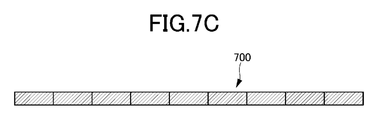
- FIG. 7C is a cross-sectional view along line CC in FIG. 1 is a cross-sectional view along FIG.
- FIG. 8 is a schematic diagram illustrating an example of a method of forming the radial recess 74 and the axial first recess 710. As shown in FIG.
- the core 7 is a collapsible core.
- Collapsible cores refer to seed cores that can be "collapsed” and removed after the casting process.
- Examples of collapsible cores include salt cores and shell cores (sand). Salt cores are more resistant to heat than shell cores, and have fewer restrictions during casting. Therefore, in this embodiment, the core 7 is preferably a salt core.
- the core 7 is formed by laminating annular cores 700 as shown in FIG. 5 in the axial direction. It should be noted that a dividing line L1 of each annular core 700 is shown in FIG. In FIG. 4, the core 7 is formed by stacking nine annular cores 700 in the axial direction. It may be set appropriately according to the length.
- the plurality of annular cores 700 forming one core 7 include an annular core 700 having cylindrical portions 77 and 78 (indicated by “annular core 700-1” in FIG. 4). However, below, unless otherwise specified, the annular core 700 without the cylindrical portions 77 and 78 (or the portion of the annular core 700-1 in the circumferential direction other than the cylindrical portions 77 and 78) will be described. .
- the annular core 700 is formed by axially compressing and hardening the material (salt for the core). Each annular core 700 has the same configuration except for the annular core 700-1 described above. The following description of the configuration of the annular core 700 relates to one annular core 700 unless otherwise specified.
- the annular core 700 has a first axial recess 710 on one axial end face (axial end face) and a second axial recess 710 on the other axial end face (axial end face). 720. Since the first axial recess 710 and the second axial recess 720 are formed by compressing the annular core 700 in the axial direction, they can be easily formed. For example, the first axial recess 710 and the second axial recess 720 can be formed by an axial protrusion (see protrusion 910 in FIG. 8) of a compression mold.
- the axial first recess 710 forms a through hole 71-1 for forming the first column 66-1 of the support case 60 described above, and the axial second recess 720 forms the support case 60 described above.
- a through hole 71-2 is formed for forming the second column portion 66-2.
- the annular core 700 has a basic surface 7100 extending in the circumferential direction at the same axial position on one end face in the axial direction (negative side in the X direction in FIG. 5).
- a basic plane 7100 is a plane perpendicular to the axial direction (rotational axis I).
- First recesses 710 recessed in the axial direction are periodically formed in the basic surface 7100 along the circumferential direction.
- the first recesses 710 are periodically set at equal intervals (constant pitch p1) except for a circumferential range R50 (see FIG. 5) corresponding to the flow path portions 951 and 952 described above.
- the first recesses 710 (and accordingly the radial recesses 74) can be evenly arranged in the circumferential direction. Also, in the core 7 (see FIG. 4) in which a plurality of annular cores 700 are stacked, the first recesses 710 (and accordingly the radial recesses 74) can be evenly arranged in the axial direction.
- the circumferential length l1 of the first recesses 710 is arbitrary, but may be set smaller than the pitch p1.
- the annular core 700 has a basic surface 7200 extending in the circumferential direction at the same axial position on the end surface on the other side in the axial direction (the positive side in the X direction in FIG. 5).
- a base plane 7200 is a plane perpendicular to the axial direction.
- Axially recessed second recesses 720 are periodically formed in the basic surface 7200 along the circumferential direction.
- the second recesses 720 are periodically set at equal intervals (constant pitch p2) except for the circumferential range R50 (see FIG. 5) corresponding to the flow path portions 951 and 952 described above.
- the pitch p2 of the second recesses 720 may differ from the pitch p1 of the first recesses 710, but is preferably the same.
- the circumferential length l2 of the second recesses 720 is arbitrary, but may be set smaller than the pitch p2.
- the circumferential length l2 of the second recess 720 may differ from the length l1 of the first recess 710, but is preferably the same.
- the pitch p2 of the second recesses 720 is the same as the pitch p1 of the first recesses 710, but out of phase. That is, the circumferential position of the second recessed portion 720 is shifted from the circumferential position of the first recessed portion 710 by a predetermined shift amount ⁇ 1.
- the predetermined shift amount ⁇ 1 is preferably set so that the circumferentially extending range of the first recessed portion 710 and the circumferentially extending range of the second recessed portion 720 do not overlap each other (that is, they overlap each other when viewed in the axial direction). set to not wrap).
- the predetermined shift amount ⁇ 1, the pitches p1 and p2, and the circumferential lengths l1 and l2 are set so that the circumferential range of the first recess 710 and the circumferential range of the second recess 720 do not overlap. is set to
- the predetermined shift amount ⁇ 1 corresponds to half the pitch p2 of the second recesses 720. That is, the predetermined shift amount ⁇ 1 is set so that each first recess 710 is located at an intermediate position between two second recesses 720 adjacent in the circumferential direction. As a result, the first recesses 710 and the second recesses 720 (and accordingly the first columnar portion 66-1 and the second columnar portion 66-2) can be arranged evenly in the circumferential direction.
- the depth d2 (the amount of recess in the axial direction) of the second recess 720 may be the same as the depth d1 (the amount of recess in the axial direction) of the first recess 710 .
- the depth d2 (amount of recess in the axial direction) of the second recess 720 is preferably the basic axial length of one annular core 700 (the length from the basic surface 7100 to the basic surface 7200). It may be significantly shorter than half of W0, for example on the order of 1/3.
- the shaft in which no recess is formed A certain range of directions extends in a strip shape along the circumferential direction.
- a strip-shaped range is also referred to as "a strip-shaped range in which no axial concave portion is formed”.
- the base length W0 may be adapted taking these trade-offs into account.
- the axial dimension of the band-shaped range in which the axial recess is not formed the smaller the circle.
- the basic axial length W0 of the annular core 700 is reduced. Therefore, the number of annular cores 700 for forming one core 7 increases as the axial dimension of the strip-shaped range in which no axial concave portion is formed is reduced. For example, if the axial dimension of the band-shaped range in which no axial concave portion is formed is set to "0", the number of annular cores 700 for forming one core 7 becomes relatively large.
- the axial dimension of the band-shaped range in which the axial concave portion is not formed to a value greater than 0 (for example, about 1/3 of W0 as described above)
- a value greater than 0 for example, about 1/3 of W0 as described above
- the necessary amount of the annular core 700 is Rigidity (for example, rigidity required from the viewpoint of shape stability during assembly) can be easily ensured.
- the annular core 700 has radial recesses 74 for forming the projections 67 of the support case 60 described above.
- the radial recesses 74 are formed axially adjacent to the first axial recesses 710, as described above, in a band-like area where no axial recesses are formed.
- the plurality of first recesses 710 and the plurality of protrusions 67 are different in axial and circumferential positions with respect to the plurality of second recesses 720 .
- the plurality of protrusions 67 extend axially over the entire length of the strip-shaped range in which no axial recesses are formed, but extend axially over a portion of the strip-shaped range in which no axial recesses are formed. It may extend, or may extend beyond a band-like area in which no axial recess is formed.
- the radial recess 74 is formed in a paired manner with the first recess 710 .
- the radial recess 74 can be formed simultaneously with the first recess 710 using the same mold.
- it may be formed using an annular upper mold 91 and an annular lower mold 92 as shown in FIG. 8 schematically shows a cross-sectional view of the annular upper mold 91 and the annular lower mold 92 (a cross-sectional view along a plane including the rotation axis I), and S800 is the state before molding. , and S801 indicates the state at the time of molding (at the time of mold clamping).
- the upper mold 91 has a convex portion 910 for forming the first concave portion 710 and a further convex portion 912 extending from the end surface of the convex portion 910
- the lower mold 92 has a concave groove 920 .
- the material MT salt for the core
- the radial recesses 74 and the first recesses 710 can be formed at the same time with the same mold.
- the upper die 91 may be provided with convex portions (another convex portion such as the convex portion 910) for forming the second concave portions 720 at different circumferential positions.
- the circumferential formation range of one radial recess 74 may be set within the circumferential formation range of the corresponding one first recess 710 so that it can be formed with such a mold.
- the core 7 capable of forming a large number of column portions 66 can be formed.
- each first concave portion 710 of one annular core 700 abuts the one annular core 700 in the axial direction. It is axially opposed to the basic surface 7200 of another annular core 700 .
- a through hole 71-1 first column portion 66-1) having peripheral walls formed by the first concave portions 710 and the basic surface 7200 is formed.
- each second recess 720 of one annular core 700 axially faces the base surface 7100 of another annular core 700 that axially contacts the one annular core 700. do.
- a through hole 71-2 second column portion 66-2 having peripheral walls formed by the second concave portions 720 and the basic surface 7100 is formed.
- the annular core 700 has the first axial recess 710 and the axial through hole instead of the radial through hole for forming the column portion 66 . of the second recess 720 is formed.
- Such a first axial recess 710 and a second axial recess 720 can be relatively easily molded as outlined with reference to FIG.
- Individual toric cores 700 can be individually manufactured in a manner that meets manufacturing requirements. Therefore, according to this embodiment, the core 7 capable of forming a large number of column portions 66 can be formed in a manner that satisfies the manufacturing requirements.
- first axial recess 710 and the second axial recess 720 are formed at different positions along the axial direction and the circumferential direction.
- a first axial recess 710 (FIG. 7A) and a second axial recess 720 (FIG. 7B) form a solid portion (FIG. 7C).
- first axial recesses 710 and second axial recesses 720 occur periodically alternately via radial recesses 74 or solid portions.
- the first columnar portion 66-1 and the second columnar portion 66-2 can be formed in a relatively high density by the staggered arrangement, and the cooling performance of the cooling water passage 95 can be enhanced.
- the rigidity of the annular core 700 is increased as described above. Therefore, the axial basic length W0 of the one annular core 700 tends to be long, which is disadvantageous for increasing the density of the arrangement of the column portions 66 . In this way, according to this embodiment, it is possible to increase the density of the arrangement of the pillars 66 while satisfying the manufacturing requirements.
- FIG. 9 is an explanatory diagram of the flow of cooling water in the cooling water passage 95 of this embodiment, and is a top view showing a part of the outer shell of the cooling water passage 95.
- FIG. 9 arrows R90, arrows R93, and arrows R94 schematically show the flow of part of the cooling water.
- 10 is a cross-sectional view along line DD in FIG. 9, and
- FIG. 11 is a cross-sectional view along line EE in FIG.
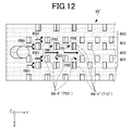
- FIG. 12 is an explanatory diagram of the flow of cooling water in a cooling water passage 95' according to a comparative example, and is a top view showing part of the outer shell of the cooling water passage 95'.
- FIG. 9 is an explanatory diagram of the flow of cooling water in the cooling water passage 95 of this embodiment, and is a top view showing a part of the outer shell of the cooling water passage 95.
- arrows R90, arrows R91, and arrows R92 schematically show the flow of part of the cooling water.
- the arrows R90 and the like are shown only for some regions, but substantially the same cooling water flow is realized for other similar regions as well. .
- the cooling water channel 95' according to the comparative example differs from the cooling water channel 95 according to the present embodiment in that it does not have the protrusion 67.
- Such a cooling water passage 95' is formed by similarly axially laminating annular cores (not shown) in which the radial recesses 74 are omitted with respect to the annular core 700 described above. Can be formed using children.
- the cooling water supplied from the inlet water passage portion 61 flows along the circumferential direction as a whole.
- Each column 66 extends perpendicularly to the flow of cooling water, and thus has the function of distributing the flow in the axial direction by obstructing the flow. That is, the flow (see arrow R90) that impinges on each pillar 66 in the circumferential direction splits in the axial direction at each pillar 66 and flows downstream.
- the columns 66 are arranged at equal intervals in the circumferential direction, but are offset in the axial direction. That is, the position of each first column 66-1 in the circumferential direction coincides with the intermediate position of each two second columns 66-2 adjacent in the circumferential direction. The position in the axial direction does not coincide with the intermediate position between each two axially adjacent second column portions 66-2.
- Such an imbalance occurs due to the strip-shaped range (see reference numeral 900 in FIGS. 9 and 12) in which no axial recess is formed. Since a flow path portion is formed that is not formed, it causes an axial deviation in the arrangement of the columns 66.
- the band-shaped range in which the axial recess is not formed has a relatively large axial dimension. (for example, about 1/3 of the basic axial length W0 of one annular core 700 as described above), it produces a significant axial deviation.
- cooling water passage 95 has a bias such that resistance to flow along the circumferential direction is smaller in the passage portion where the column portion 66 is not formed than in other portions.
- cooling water passage 95 if there is a passage portion where the column portion 66 is not formed (a passage portion relating to the band-shaped range where the axial concave portion is not formed), a large amount of cooling water flows in the passage portion, and the cooling water flow tends to be biased.
- a plurality of protrusions 67 are formed in the band-shaped range where no axial recesses are formed, so that the above-described inconvenience caused in the comparative example can be reduced.
- the projection 67 acts as a resistance to the flow in the circumferential direction due to the reduction (rapid contraction) of the cross-sectional area. can be reduced.
- part of the cooling water flowing in the circumferential direction toward the protrusion 67 flows to both axial sides of the protrusion 67, which occurs in the comparative example.
- Such bias as described above can be reduced.
- the function of such protrusions 67 that is, the function of reducing the flow rate in the channel portion where the columnar portions 66 are not formed, is also referred to as the "flow equalization function".
- the protrusion 67 as described above has a shape similar to the column portion 66 as the radial height (see depth H1) increases, and can function similarly to the column portion 66 .
- the radial height of the projection 67 becomes the same as that of the column 66, the column 66 will be substantially enlarged. The resistance to the flow of cooling water becomes excessive in the passage portion where the portion 66 is not formed.
- the radial height (dimension) of the protrusion 67 is adapted to meet the manufacturing requirements as described above and to properly realize the flow equalization function described above.
- the radial recess 74 corresponding to the radial height of the projection 67 is significantly smaller than the radial thickness H0 of the core 7 .
- the radial thickness H0 of the core 7 is, for example, about 4 mm to 6 mm so that the radial size of the support case 60 does not become excessive.
- the radial height of the projection 67 (the radial depth H1 of the recess 74) may be between 0.5 mm and 1.5 mm.
- the support case 60 having a function of equalizing the flow rate and excellent cooling performance while reducing the physical size in the radial direction.
- the radial height of the projection 67 does not have to be constant due to the draft angle of the mold (see FIG. 8) or the like.
- the protrusion 67 is formed adjacent to the first column 66-1. It may be formed adjacent to portion 66-2.
- FIG. 13 is a schematic flow chart showing the flow of the manufacturing method of the stator 10b.
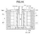
- FIG. 14 is a diagram for explaining the manufacturing method shown in FIG. 13, and is a cross-sectional view schematically showing a state during the casting process.
- the manufacturing method of the stator 10b first includes preparing the stator core 112 (step S30).
- the stator core 112 is made of, for example, an annular magnetic layered steel plate.
- the steel plates may not be connected to each other, or may be connected by welding or the like.
- the method for manufacturing the stator 10b includes setting the masking mold 170 on the stator core 112 (step S31).
- the masking mold 170 has a function of protecting the axial end faces of the stator core 112 and the radially inner surface of the stator core 112 (the surface on which the rotor core is accommodated).
- the masking mold 170 includes an upper masking member 171, a lower masking member 172, and tightening bolts 173. As shown in FIG.
- the method for manufacturing the stator 10b includes filling inert gas into the space 80 of the stator core 112 (step S32).
- inert gas The role of inert gas will be described later.
- the method for manufacturing the stator 10b includes setting the stator core 112 in a casting mold 1400 (schematically shown in FIG. 14) (step S33). At this time, stator core 112 is set in casting mold 1400 with masking mold 170 attached thereto.
- the method for manufacturing the stator 10b includes a preparation step (step S34A) of preparing a plurality of annular cores 700 described above, and a stacking step of stacking a plurality of prepared annular cores 700 concentrically and axially. and (step S34B).
- a core 7 is thus obtained.
- the core 7A can also be obtained by the same method as the core 7.
- the stacking of the plurality of annular cores 700 may be performed before being set in the mold. In this case, the annular cores 700 may be adhered to each other so as to maintain the laminated state. Alternatively, such lamination may be performed when set in the casting mold 1400 (which may be realized substantially simultaneously with the next step S35).
- the method for manufacturing the stator 10b includes setting the core 7 and the core 7A obtained in step S34B in the casting mold 1400 (step S35).
- the core 7 and the core 7A are set radially outside the stator core 112 (see FIG. 14).
- the core 7 is spaced radially outward from the radially inner stator core 112
- the core 7A is spaced radially outward from the core 7, and
- it is set radially inwardly spaced from the radially outer casting mold 1400 .
- FIG. 14 is a schematic cross-sectional view showing a state in which an aluminum material is poured into a mold in the casting process.
- the cores 7 and 7A are each schematically shown in cross-sectional view in the form of a cylinder, and the filled aluminum material is schematically shown in a hatched area 90. As shown in FIG.
- the aluminum material flows so as to cover the outer peripheral surface of the stator core 112 .
- support case 60 can be firmly joined to the outer peripheral surface of stator core 112 .
- the outer peripheral surface of stator core 112 is welded to support case 60 before it is set in the mold in step S33.
- An facilitating treatment eg, an aluminizing treatment
- the aluminizing treatment may be realized by immersing the stator core 112 in a tank such as an aluminum tank (for example, a molten aluminum tank) while the space 80 is filled with an inert gas.
- the injected aluminum material flows radially from the inside in such a manner as to fill radial gaps between the stator core 112, the core 7, the core 7A, and the radially outer casting mold 1400.
- the aluminum material covers the outer peripheral surface and the inner peripheral surface of each of the plurality of annular cores 700 that form the core 7 (the same applies to the core 7A), and the through holes 71 and each It flows so as to fill the radial recess 74 .
- the support case 60 having the cooling water passage 95 with the columns 66 and the protrusions 67 and the case oil passage 35 with the columns 68 and the protrusions 69 can be formed.
- the stator core 112 is set in the casting mold 1400 with the masking mold 170 attached. Therefore, it is possible to reduce the possibility of the aluminum material adhering to the end surfaces 1125 and 1126 of the stator core 112 and the possibility of the aluminum material entering the space 80 .
- the casting process of step S36 is performed while the space 80 is filled with an inert gas. If the casting process of step S36 is performed with the space 80 filled with an inert gas, otherwise (that is, the casting process of step S36 is performed with the space 80 not filled with an inert gas) In this case, the damage to the insulating film of the steel plate forming the stator core 112 can be reduced.
- step S36 when the casting process of step S36 is performed in a state in which the space 80 is not filled with an inert gas (that is, an atmosphere containing oxygen), the radially inner surface of the stator core 112 is made of a high-temperature aluminum material. It will be exposed to a high-temperature atmosphere due to As a result, the insulating film of each steel plate of stator core 112 may be destroyed, and the magnetic performance of stator core 112 may not be the desired performance.
- an inert gas that is, an atmosphere containing oxygen
- step S36 when the casting process of step S36 is performed with the space 80 filled with an inert gas, even if the stator core 112 is exposed to a high-temperature atmosphere, the atmosphere does not substantially contain oxygen. Generation of oxide scale is prevented or effectively reduced. As a result, the insulating film of each steel plate of stator core 112 is protected, and the possibility that the magnetic performance of stator core 112 will not be the desired performance can be effectively reduced. It should be noted that this also applies to the case where the above-described aluminizing treatment is performed in a state in which the space 80 is filled with an inert gas.
- the method for manufacturing the stator 10b includes removing the cores 7, 7A for forming the case oil passage 35 and the cooling water passage 95 by "collapse” (step S38) (an example of the removal step ). If the cores 7 and 7A are salt cores, they can be removed by "collapse” by pouring water or the like as described above. As a result, the above-described case oil passage 35 and cooling water passage 95 are formed inside the support case 60 .
- the method for manufacturing the stator 10b includes removing the masking mold 170 described above from the stator core 112 (step S39). In addition, this step S39 may be performed before step S38 mentioned above.
- the method for manufacturing the stator 10b includes various finishing steps such as winding the stator coil 114 around the stator core 112 (step S40).
- stator 10b in which the support case 60 and the stator core 112 are firmly joined can be easily manufactured.
- a rotor (not shown) is assembled radially inwardly of the stator 10b manufactured in this manner to form the rotating electric machine 10. As shown in FIG. 13
- each step may be executed in sequence as appropriate.
- steps S34A to S35 may be performed before step S33.
- the example shown in FIG. 13 relates to a method of integrally forming the support case 60 around the stator core 112. Separately from the stator core 112, the cores 7 and 7A are set in a mold to form the support case 60 alone. Manufacturing is also possible.
- the protrusion 67 in the support case 60 protrudes radially inward from the boundary wall surface portion 652 , but protrudes radially outward from the inner side wall surface portion 651 . may protrude from the Alternatively, the protrusion 67 may be provided on the boundary wall surface portion 652 so as to protrude radially inward, and may be provided on the inner diameter side wall surface portion 651 so as to protrude radially outward. The same applies to the protrusion 69 associated with the case oil passage 35 .
- the column portion 66 (the column portion 68 is also the same, and the same shall apply hereinafter) has a cylindrical shape, but the cross-sectional shape is arbitrary.
- the cross-sectional shape need not be constant.
- the column portion 66 may have a constriction such that the cross-sectional area becomes smaller near the central portion in the height direction.
Landscapes
- Engineering & Computer Science (AREA)
- Power Engineering (AREA)
- Manufacturing & Machinery (AREA)
- Mechanical Engineering (AREA)
- Iron Core Of Rotating Electric Machines (AREA)
Abstract
Description
冷媒流入孔を形成する第1部位と、
冷媒流出孔を形成する第2部位と、
外部に連通することなく前記冷媒流入孔と前記冷媒流出孔とを連通する冷媒路を形成する第3部位と、を備え、
前記第3部位は、前記冷媒路において、冷媒の流れに対して垂直な第1方向にそれぞれ立設される複数の第1柱部と、前記第1方向にそれぞれ突設される複数の突部とを備え、
前記冷媒路に暴露する前記複数の第1柱部の表面及び前記突部の表面に前記冷媒が接する、冷却部材が提供される。
Claims (7)
- 回転電機用の冷却部材であって、
冷媒流入孔を形成する第1部位と、
冷媒流出孔を形成する第2部位と、
外部に連通することなく前記冷媒流入孔と前記冷媒流出孔とを連通する冷媒路を形成する第3部位と、を備え、
前記第3部位は、前記冷媒路において、冷媒の流れに対して垂直な第1方向にそれぞれ立設される複数の第1柱部と、前記第1方向にそれぞれ突設される複数の突部とを備え、
前記冷媒路に暴露する前記複数の第1柱部の表面及び前記突部の表面に前記冷媒が接する、冷却部材。 - 前記複数の第1柱部及び前記複数の突部は、対で設けられ、
前記複数の第1柱部及び前記複数の突部に係る複数の対は、前記第1方向に直交しかつ互いに対して直交する2方向を第2方向及び第3方向とした場合に、前記第2方向及び前記第3方向のそれぞれに沿って等間隔にかつ互いに隣接することなく、配置される、請求項1に記載の冷却部材。 - 前記第3部位は、径方向外側の円筒状の第1壁部と、径方向内側の円筒状の第2壁部とを、前記回転電機の回転軸を中心として同心状に有するとともに、前記第1壁部と前記第2壁部との間に前記冷媒路を形成し、
前記第2方向及び前記第3方向は、前記回転軸を基準とした周方向及び軸方向に対応し、
前記複数の対のそれぞれにおいて、前記第1柱部及び前記突部は軸方向に隣り合う、請求項2に記載の冷却部材。 - 前記第3部位は、複数の第2柱部を、更に備え、
前記冷媒路に暴露する前記複数の第2柱部の表面に前記冷媒が接し、
前記複数の第2柱部は、前記複数の第1柱部及び前記複数の突部に対して、軸方向及び周方向の位置が異なる、請求項3に記載の冷却部材。 - 前記突部の前記第1方向の寸法は、0.5mmから1.5mmの間である、請求項1から4のうちのいずれか1項に記載の冷却部材。
- ステータコアと、
前記ステータコアの径方向外側に接合される冷却部材とを含み、
前記冷却部材は、
冷媒流入孔を形成する第1部位と、
冷媒流出孔を形成する第2部位と、
外部に連通することなく前記冷媒流入孔と前記冷媒流出孔とを連通する冷媒路を形成する第3部位と、を備え、
前記第3部位は、前記冷媒路において、冷媒の流れに対して垂直な第1方向にそれぞれ立設される複数の第1柱部及び複数の突部を備え、
前記冷媒路に暴露する前記複数の第1柱部の表面及び前記突部の表面に前記冷媒が接する、回転電機。 - 回転電機に用いられる円環状の冷却部材の製造方法であって、
軸方向端面に軸方向の凹部をそれぞれ有しかつ外周面又は内周面に径方向の凹部をそれぞれ有する円環状の複数の崩壊性中子を準備する準備工程と、
前記複数の崩壊性中子を、前記軸方向の凹部により径方向の貫通孔を形成する態様で、同心状にかつ軸方向に積層する積層工程と、
金型内に前記複数の崩壊性中子が積層された状態で、前記金型内に前記冷却部材の材料を、前記材料が前記複数の崩壊性中子のそれぞれの外周面及び内周面を覆いかつ前記貫通孔を埋めるように、注湯する鋳造工程と、
前記鋳造工程の後に、前記複数の崩壊性中子を除去する除去工程とを含む、製造方法。
Priority Applications (4)
| Application Number | Priority Date | Filing Date | Title |
|---|---|---|---|
| JP2023533175A JPWO2023282307A1 (ja) | 2021-07-09 | 2022-07-06 | |
| EP22837721.4A EP4329164A4 (en) | 2021-07-09 | 2022-07-06 | COOLING ELEMENT FOR ROTARY ELECTRIC MACHINE, ROTARY ELECTRIC MACHINE AND METHOD FOR MANUFACTURING COOLING ELEMENT FOR ROTARY ELECTRIC MACHINE |
| CN202280048024.7A CN117678150A (zh) | 2021-07-09 | 2022-07-06 | 旋转电机用的冷却部件、旋转电机、旋转电机用的冷却部件的制造方法 |
| US18/563,155 US20240275231A1 (en) | 2021-07-09 | 2022-07-06 | Cooling member for rotating electrical machine, rotating electrical machine, and method for manufacturing cooling member for rotating electrical machine |
Applications Claiming Priority (2)
| Application Number | Priority Date | Filing Date | Title |
|---|---|---|---|
| JP2021114607 | 2021-07-09 | ||
| JP2021-114607 | 2021-07-09 |
Publications (1)
| Publication Number | Publication Date |
|---|---|
| WO2023282307A1 true WO2023282307A1 (ja) | 2023-01-12 |
Family
ID=84800738
Family Applications (1)
| Application Number | Title | Priority Date | Filing Date |
|---|---|---|---|
| PCT/JP2022/026888 Ceased WO2023282307A1 (ja) | 2021-07-09 | 2022-07-06 | 回転電機用の冷却部材、回転電機、回転電機用の冷却部材の製造方法 |
Country Status (5)
| Country | Link |
|---|---|
| US (1) | US20240275231A1 (ja) |
| EP (1) | EP4329164A4 (ja) |
| JP (1) | JPWO2023282307A1 (ja) |
| CN (1) | CN117678150A (ja) |
| WO (1) | WO2023282307A1 (ja) |
Families Citing this family (1)
| Publication number | Priority date | Publication date | Assignee | Title |
|---|---|---|---|---|
| US12320367B2 (en) * | 2023-02-01 | 2025-06-03 | Garrett Transportation I Inc. | Turbomachine with coolant jacket and turbulator insert member |
Citations (6)
| Publication number | Priority date | Publication date | Assignee | Title |
|---|---|---|---|---|
| JPH0819218A (ja) * | 1994-06-28 | 1996-01-19 | Honda Motor Co Ltd | 回転電機の冷却構造 |
| US5623175A (en) * | 1996-03-19 | 1997-04-22 | General Motors Corporation | Thermally efficient, liquid cooled housing for dynamoelectric machine |
| JP2010041835A (ja) * | 2008-08-06 | 2010-02-18 | Mitsubishi Motors Corp | 回転電機 |
| DE102009047215A1 (de) | 2009-11-27 | 2011-06-01 | Robert Bosch Gmbh | Elektrische Maschine |
| JP2021040466A (ja) * | 2019-09-05 | 2021-03-11 | 株式会社デンソー | 電気機器のフレーム及びその製造方法 |
| JP2021093891A (ja) * | 2019-12-12 | 2021-06-17 | アイシン・エィ・ダブリュ株式会社 | 回転電機の製造方法 |
Family Cites Families (5)
| Publication number | Priority date | Publication date | Assignee | Title |
|---|---|---|---|---|
| WO2004025808A1 (ja) * | 2002-09-13 | 2004-03-25 | Aisin Aw Co., Ltd. | 駆動装置 |
| DE102013222697A1 (de) * | 2013-11-08 | 2015-05-13 | Em-Motive Gmbh | Elektrische Maschine mit in ein Gehäuse integriertem Kühlkanal |
| SI24669A (sl) * | 2014-01-26 | 2015-09-30 | Skiping D.O.O. | Hladilnik elektromotorja z množico istosmerno orientiranih točkovnih reber |
| WO2016194158A1 (ja) * | 2015-06-03 | 2016-12-08 | 三菱電機株式会社 | 液冷冷却器、及び液冷冷却器に於ける放熱フィンの製造方法 |
| FR3077940B1 (fr) * | 2018-02-14 | 2022-09-02 | Psa Automobiles Sa | Carter, moteur electrique comprenant un carter, modele perdu d’un carter et procede de fabrication d’un carter de moteur electrique refroidi |
-
2022
- 2022-07-06 WO PCT/JP2022/026888 patent/WO2023282307A1/ja not_active Ceased
- 2022-07-06 JP JP2023533175A patent/JPWO2023282307A1/ja not_active Withdrawn
- 2022-07-06 CN CN202280048024.7A patent/CN117678150A/zh active Pending
- 2022-07-06 US US18/563,155 patent/US20240275231A1/en active Pending
- 2022-07-06 EP EP22837721.4A patent/EP4329164A4/en not_active Withdrawn
Patent Citations (6)
| Publication number | Priority date | Publication date | Assignee | Title |
|---|---|---|---|---|
| JPH0819218A (ja) * | 1994-06-28 | 1996-01-19 | Honda Motor Co Ltd | 回転電機の冷却構造 |
| US5623175A (en) * | 1996-03-19 | 1997-04-22 | General Motors Corporation | Thermally efficient, liquid cooled housing for dynamoelectric machine |
| JP2010041835A (ja) * | 2008-08-06 | 2010-02-18 | Mitsubishi Motors Corp | 回転電機 |
| DE102009047215A1 (de) | 2009-11-27 | 2011-06-01 | Robert Bosch Gmbh | Elektrische Maschine |
| JP2021040466A (ja) * | 2019-09-05 | 2021-03-11 | 株式会社デンソー | 電気機器のフレーム及びその製造方法 |
| JP2021093891A (ja) * | 2019-12-12 | 2021-06-17 | アイシン・エィ・ダブリュ株式会社 | 回転電機の製造方法 |
Also Published As
| Publication number | Publication date |
|---|---|
| US20240275231A1 (en) | 2024-08-15 |
| EP4329164A1 (en) | 2024-02-28 |
| JPWO2023282307A1 (ja) | 2023-01-12 |
| EP4329164A4 (en) | 2024-03-27 |
| CN117678150A (zh) | 2024-03-08 |
Similar Documents
| Publication | Publication Date | Title |
|---|---|---|
| JP3603784B2 (ja) | 回転電機 | |
| JP5113306B2 (ja) | 回転電機のケース | |
| US9083221B2 (en) | Rotor assembly with integral cast conductor bars and first end rings and welded second end rings and method of manufacturing same | |
| JP7115912B2 (ja) | ロータの製造方法 | |
| US20220263378A1 (en) | Rotating electrical machine and method for manufacturing rotating electrical machine | |
| KR20180032616A (ko) | 전기 기계를 위한 냉각 시스템 | |
| WO2023282307A1 (ja) | 回転電機用の冷却部材、回転電機、回転電機用の冷却部材の製造方法 | |
| JP2023011201A (ja) | 冷却部材の製造方法及び回転電機 | |
| JP6197462B2 (ja) | ステータコイルの冷却構造及びステータコイルの冷却構造の製造方法 | |
| JP7395758B2 (ja) | 回転電機用冷却部材の製造方法 | |
| JP2021093891A (ja) | 回転電機の製造方法 | |
| JP2019080365A (ja) | 回転電機のステータ | |
| JP4093093B2 (ja) | 回転電機 | |
| JP6261818B1 (ja) | 回転電機冷却装置 | |
| JP2014039379A (ja) | 回転電機用ハウジングの製造方法 | |
| JP3823844B2 (ja) | 回転電機およびその製造方法 | |
| JP7414610B2 (ja) | 崩壊性中子の製造方法 | |
| CN107749699B (zh) | 转子的加工方法 | |
| WO2022030282A1 (ja) | 回転電機用ステータの製造方法 | |
| CN224123957U (zh) | 一种定子铁心 | |
| WO2023054163A1 (ja) | 回転電機及び回転電機の製造方法 | |
| JP2023125010A (ja) | 回転電機用ステータの製造方法 | |
| JP7603859B1 (ja) | ロータ構造 | |
| JP2022186316A (ja) | 回転電機及び回転電機の製造方法 | |
| JP2010236422A (ja) | 圧縮機 |
Legal Events
| Date | Code | Title | Description |
|---|---|---|---|
| 121 | Ep: the epo has been informed by wipo that ep was designated in this application |
Ref document number: 22837721 Country of ref document: EP Kind code of ref document: A1 |
|
| WWE | Wipo information: entry into national phase |
Ref document number: 18563155 Country of ref document: US |
|
| WWE | Wipo information: entry into national phase |
Ref document number: 2022837721 Country of ref document: EP |
|
| WWE | Wipo information: entry into national phase |
Ref document number: 2023533175 Country of ref document: JP |
|
| ENP | Entry into the national phase |
Ref document number: 2022837721 Country of ref document: EP Effective date: 20231122 |
|
| WWE | Wipo information: entry into national phase |
Ref document number: 202280048024.7 Country of ref document: CN |
|
| NENP | Non-entry into the national phase |
Ref country code: DE |