WO2023286187A1 - 通信制御方法及び通信制御装置 - Google Patents
通信制御方法及び通信制御装置 Download PDFInfo
- Publication number
- WO2023286187A1 WO2023286187A1 PCT/JP2021/026399 JP2021026399W WO2023286187A1 WO 2023286187 A1 WO2023286187 A1 WO 2023286187A1 JP 2021026399 W JP2021026399 W JP 2021026399W WO 2023286187 A1 WO2023286187 A1 WO 2023286187A1
- Authority
- WO
- WIPO (PCT)
- Prior art keywords
- radio station
- signal
- antennas
- distributed antenna
- transmission
- Prior art date
- Legal status (The legal status is an assumption and is not a legal conclusion. Google has not performed a legal analysis and makes no representation as to the accuracy of the status listed.)
- Ceased
Links
Images







Classifications
-
- H—ELECTRICITY
- H04—ELECTRIC COMMUNICATION TECHNIQUE
- H04B—TRANSMISSION
- H04B7/00—Radio transmission systems, i.e. using radiation field
- H04B7/02—Diversity systems; Multi-antenna system, i.e. transmission or reception using multiple antennas
- H04B7/04—Diversity systems; Multi-antenna system, i.e. transmission or reception using multiple antennas using two or more spaced independent antennas
- H04B7/06—Diversity systems; Multi-antenna system, i.e. transmission or reception using multiple antennas using two or more spaced independent antennas at the transmitting station
-
- H—ELECTRICITY
- H04—ELECTRIC COMMUNICATION TECHNIQUE
- H04B—TRANSMISSION
- H04B7/00—Radio transmission systems, i.e. using radiation field
- H04B7/02—Diversity systems; Multi-antenna system, i.e. transmission or reception using multiple antennas
- H04B7/04—Diversity systems; Multi-antenna system, i.e. transmission or reception using multiple antennas using two or more spaced independent antennas
- H04B7/0408—Diversity systems; Multi-antenna system, i.e. transmission or reception using multiple antennas using two or more spaced independent antennas using two or more beams, i.e. beam diversity
-
- H—ELECTRICITY
- H04—ELECTRIC COMMUNICATION TECHNIQUE
- H04B—TRANSMISSION
- H04B7/00—Radio transmission systems, i.e. using radiation field
- H04B7/02—Diversity systems; Multi-antenna system, i.e. transmission or reception using multiple antennas
- H04B7/022—Site diversity; Macro-diversity
-
- H—ELECTRICITY
- H04—ELECTRIC COMMUNICATION TECHNIQUE
- H04B—TRANSMISSION
- H04B7/00—Radio transmission systems, i.e. using radiation field
- H04B7/02—Diversity systems; Multi-antenna system, i.e. transmission or reception using multiple antennas
- H04B7/04—Diversity systems; Multi-antenna system, i.e. transmission or reception using multiple antennas using two or more spaced independent antennas
- H04B7/06—Diversity systems; Multi-antenna system, i.e. transmission or reception using multiple antennas using two or more spaced independent antennas at the transmitting station
- H04B7/0686—Hybrid systems, i.e. switching and simultaneous transmission
- H04B7/0695—Hybrid systems, i.e. switching and simultaneous transmission using beam selection
-
- H—ELECTRICITY
- H04—ELECTRIC COMMUNICATION TECHNIQUE
- H04B—TRANSMISSION
- H04B7/00—Radio transmission systems, i.e. using radiation field
- H04B7/02—Diversity systems; Multi-antenna system, i.e. transmission or reception using multiple antennas
- H04B7/04—Diversity systems; Multi-antenna system, i.e. transmission or reception using multiple antennas using two or more spaced independent antennas
- H04B7/06—Diversity systems; Multi-antenna system, i.e. transmission or reception using multiple antennas using two or more spaced independent antennas at the transmitting station
- H04B7/0686—Hybrid systems, i.e. switching and simultaneous transmission
- H04B7/0695—Hybrid systems, i.e. switching and simultaneous transmission using beam selection
- H04B7/06952—Selecting one or more beams from a plurality of beams, e.g. beam training, management or sweeping
- H04B7/06956—Selecting one or more beams from a plurality of beams, e.g. beam training, management or sweeping using a selection of antenna panels
-
- H—ELECTRICITY
- H04—ELECTRIC COMMUNICATION TECHNIQUE
- H04B—TRANSMISSION
- H04B7/00—Radio transmission systems, i.e. using radiation field
- H04B7/02—Diversity systems; Multi-antenna system, i.e. transmission or reception using multiple antennas
- H04B7/04—Diversity systems; Multi-antenna system, i.e. transmission or reception using multiple antennas using two or more spaced independent antennas
- H04B7/08—Diversity systems; Multi-antenna system, i.e. transmission or reception using multiple antennas using two or more spaced independent antennas at the receiving station
- H04B7/0868—Hybrid systems, i.e. switching and combining
- H04B7/0874—Hybrid systems, i.e. switching and combining using subgroups of receive antennas
-
- H—ELECTRICITY
- H04—ELECTRIC COMMUNICATION TECHNIQUE
- H04B—TRANSMISSION
- H04B7/00—Radio transmission systems, i.e. using radiation field
- H04B7/02—Diversity systems; Multi-antenna system, i.e. transmission or reception using multiple antennas
- H04B7/04—Diversity systems; Multi-antenna system, i.e. transmission or reception using multiple antennas using two or more spaced independent antennas
- H04B7/08—Diversity systems; Multi-antenna system, i.e. transmission or reception using multiple antennas using two or more spaced independent antennas at the receiving station
- H04B7/0868—Hybrid systems, i.e. switching and combining
- H04B7/088—Hybrid systems, i.e. switching and combining using beam selection
Definitions
- the present invention relates to a communication control method and a communication control device.
- Non-Patent Document 1 There is a beamforming technology that forms a beam that concentrates power in a specific direction.
- the free space propagation loss is greater than in the low frequency band such as the microwave band, so it is necessary to use beamforming to compensate for the free space propagation loss.
- Beamforming is a PP (Point-to-Point) type communication in which the combination of wireless stations that communicate with each other is always fixed, and the positional relationship between both wireless stations and the surroundings of both wireless stations. If the propagation environment does not change, it is possible to use a fixed beam formed in a specific direction in advance when installing a radio station or the like. However, in the case of P-MP (Point-to-Multi Point) type communication that accommodates multiple radio stations, or in the case that at least one of the radio stations communicating with each other moves, A beam formed in a specific direction cannot be used fixedly because the appropriate formation direction changes.
- P-MP Point-to-Multi Point
- adaptive beamforming In such a case, it is necessary to adaptively change the direction of beam formation according to changes in the positional relationship between both radio stations and the propagation environment around both radio stations.
- Such beamforming that adaptively controls the direction of beam formation is called adaptive beamforming.
- adaptive beamforming does not require a mechanical drive to change the forming direction of the beam.
- beams with directivity are formed by adjusting phase relationships of radio waves radiated from a plurality of antenna elements.
- a beam ID (Identifier) that can uniquely identify each beam is associated with the plurality of beams.
- a beam specifying signal including a beam ID is transmitted and received between both wireless stations using a beam associated with the beam ID. Then, based on the result of transmission and reception of the beam identification signal by each beam, the optimum beam and the beam ID associated with the beam are identified between both wireless stations.
- Adaptive beamforming can suppress the increase of overhead by such beam selection.
- one radio station transmits a beam specifying signal to the other radio station.
- the beam identification signal here is a signal that enables one radio station to identify the beam used for transmission of the beam identification signal by the other radio station.
- one radio station performs transmission control so that the beam specifying signals transmitted by each beam do not interfere with each other.
- one radio station shifts the transmission timing of the beam specifying signal for each beam and transmits the signals in order.
- the operation of the radio station to sequentially transmit the beam specifying signal by shifting the transmission timing of each beam may be referred to as "sweep".
- the other radio station measures the reception quality of the beam-specific signals sequentially transmitted by each beam from the one radio station.
- the other radio station selects, for example, the beam specifying signal with the best reception quality.
- the other radio station transmits a signal containing information based on the selected beam specifying signal (hereinafter referred to as a "feedback signal") to the one radio station.
- feedback signal a signal containing information based on the selected beam specifying signal
- a beam search signal including a beam ID (Identifier) for identifying the beam used by one radio station can be used.
- the beam search signal here is, for example, SSW (Sector Sweep Frame) defined in IEEE802.11ay (see, for example, Non-Patent Document 6), or SS/PBCH (Synchronization Signal / Physical Broadcast Channel) (see, for example, Non-Patent Document 2), etc.
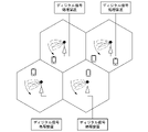
- FIG. 13 shows a general system configuration of a conventional wireless communication system.
- a digital signal processor for transmitting and receiving signals and a base station antenna are connected to each other in a one-to-one relationship. That is, in this case, one cell is formed for one base station antenna.
- one terminal device is connected to one base station antenna that exists only in the cell.
- FIG. 14 shows a general system configuration of a conventional distributed antenna system.
- digital signal processors for transmitting and receiving signals and distributed antennas are connected in a one-to-many manner. That is, in a distributed antenna system, one cell is formed by a plurality of distributed antennas. In this configuration, one terminal device is connected to one of a plurality of distributed antennas existing within the cell.
- a communication control device is connected to the digital signal processing device.
- the communication control device controls distributed antennas connected to each terminal device for wireless communication, and controls beams used by the distributed antennas.
- a communication control device is used for centralized control. In this case, the communication control device further performs processing such as user scheduling and resource control.
- the terminal device can establish a wireless communication connection with other distributed antennas present in the cell.
- selecting the optimal distributed antenna and the optimal beam is referred to as "antenna beam selection”.
- antenna beam selection in a distributed antenna system is performed in the following procedure.
- one radio station for example, a receiving station transmits a beam specifying signal to the other radio station (for example, a terminal device).
- the other radio station for example, a terminal device.
- one radio station sweeps so that the beam specifying signals transmitted by each beam do not interfere with each other, as shown in FIG.
- FIG. 15 is a schematic diagram showing an outline of a sweep by a conventional distributed antenna system.
- the other radio station measures the reception quality of beam-specific signals sequentially transmitted by each distributed antenna and each beam.
- the other radio station identifies, for example, the beam specific signal with the best reception quality.
- the other radio station transmits a feedback signal indicating the identification result to the one radio station.
- distributed antenna systems using high frequency bands need to periodically select beams at an appropriate frequency in order to follow propagation path fluctuations caused by the movement of terminal devices and changes in the surrounding environment. be.
- the time required for one beam selection becomes too long due to an increase in the number of distributed antennas, the time required for the beam selection may become longer than the beam selection execution cycle. In this case, the beam selection cannot be completed within the beam selection execution period, making it difficult to perform the data transmission itself.
- One aspect of the present invention is a transmission step of simultaneously transmitting a beam specifying signal including the same beam identifier from a plurality of antennas to a radio station using a transmission beam associated with the beam identifier for each beam identifier; a receiving step of receiving, by the plurality of antennas, a report signal including a selected beam identifier indicating a beam identifier selected based on the reception quality of the beam specifying signal for each of the beam identifiers in the plurality of antennas; selection of selecting an antenna to be used for communication with the radio station based on the reception quality of the received report signal, and selecting the transmission beam associated with the selected beam identifier as the transmission beam to be used for communication with the radio station; and a communication control method.
- One aspect of the present invention includes a transmission step of transmitting a beam specifying signal from a plurality of antennas to a wireless station at a transmission timing predetermined for each of the transmission beams using a plurality of transmission beams in sequence; a receiving step of respectively receiving, by the plurality of antennas, a report signal containing information based on the beam specifying signal selected based on the reception timing and reception quality of the beam specifying signal for each beam; a selection step of selecting an antenna to be used for communication with the radio station based on the received quality of the reported signal, and selecting a transmission beam to be used for communication with the radio station based on information included in the report signal; and a communication control method.
- One aspect of the present invention is a communication control method for a radio communication system having a first radio station and a second radio station, wherein the first radio station transmits a beam specifying signal including the same beam identifier to the a first transmission step of simultaneously transmitting for each beam identifier from a plurality of antennas to a second radio station using transmission beams linked to beam identifiers; and a first receiving step of receiving the beam specifying signal transmitted to the second radio station, based on the reception quality of the beam specifying signal for each beam identifier, selecting a specific beam identifier from the plurality of beam identifiers; a first selection step of selecting a selected beam identifier that is the second radio station transmitting a report signal including the selected beam identifier to the first radio station; a second receiving step of receiving the report signals respectively by the plurality of antennas; and the first radio station communicating with the second radio station based on the reception quality of the report signals respectively received by the plurality of antennas.
- a beam specifying signal including the same beam identifier is simultaneously transmitted from a plurality of antennas to a radio station by transmission beams associated with the beam identifier for each beam identifier, and the beam at the radio station a transmitting/receiving unit for receiving, by the plurality of antennas, a report signal including a selected beam identifier indicating a beam identifier selected based on the reception quality of the beam specifying signal for each identifier; a selection unit that selects an antenna to be used for communication with the radio station based on the reception quality of the report signal, and selects the transmission beam associated with the selected beam identifier as the transmission beam to be used for communication with the radio station; It is a communication control device comprising
- a plurality of transmission beams are sequentially used to transmit a beam specifying signal from a plurality of antennas to a radio station at transmission timings predetermined for each of the transmission beams; a transmitting/receiving unit configured to receive, by the plurality of antennas, a report signal including information based on the beam specifying signal selected based on the reception timing and reception quality of the beam specifying signal; a selection unit that selects an antenna to be used for communication with the radio station based on the reception quality of the report signal, and selects a transmission beam to be used for communication with the radio station based on information included in the report signal. It is a communication control device.
- beam selection can be performed without increasing the time required for beam selection in response to an increase in the number of distributed antennas.
- FIG. 2 is a block diagram showing the functional configuration of a communication control device 600 of a conventional distributed antenna system 6;
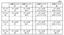
- FIG. 6 is a diagram showing beam allocation information 611 generated by a beam specifying signal transmission instructing section 601 of a conventional distributed antenna system 6.
- FIG. FIG. 4 is a block diagram showing a functional configuration of a terminal device 900 of a conventional distributed antenna system 6;
- 6 is a flow chart showing the operation of a communication control device 600 of a conventional distributed antenna system 6;
- 6 is a flow chart showing the operation of a terminal device 900 of a conventional distributed antenna system 6;
- 1 is a schematic diagram showing an outline of beam selection by a distributed antenna system according to a first embodiment of the present invention;
- FIG. 1 is an overall configuration diagram of a distributed antenna system 1 according to a first embodiment of the present invention
- FIG. 2 is a block diagram showing the functional configuration of a communication control device 100 of the distributed antenna system 1 according to the first embodiment of the present invention
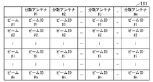
- FIG. 3 is a diagram showing beam allocation information 111 generated by the same beam search signal simultaneous transmission instructing section 101 of the distributed antenna system 1 according to the first embodiment of the present invention
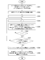
- 4 is a flow chart showing the operation of the communication control device 100 of the distributed antenna system 1 according to the first embodiment of the present invention
- FIG. 1 is an overall configuration diagram of a distributed antenna system 1 according to a first embodiment of the present invention
- FIG. 2 is a block diagram showing the functional configuration of a communication control device 100 of the distributed antenna system 1 according to the first embodiment of the present invention
- FIG. 3 is a diagram showing beam allocation information 111 generated by the same beam search signal simultaneous transmission instructing section 101 of the distributed antenna system 1 according to the first embodiment of the present invention
- 4 is a flow chart showing the operation of
- FIG. 4 is a block diagram showing the functional configuration of a communication control device 100a of a distributed antenna system according to a second embodiment of the present invention
- 9 is a flow chart showing the operation of the communication control device 100a of the distributed antenna system according to the second embodiment of the present invention
- 1 is a diagram showing a general system configuration of a conventional wireless communication system
- FIG. 1 is a diagram showing a general system configuration of a conventional distributed antenna system
- FIG. 10 is a schematic diagram showing an outline of a sweep by a conventional distributed antenna system
- the distributed antenna system 6 includes a communication control device 600, a digital signal processing device 700, distributed antennas 800-1 to 800-4, and a plurality of terminal devices 900. be.
- digital signal processing device 700 is connected to communication control device 600 and distributed antennas 800-1 to 800-4.
- Communication control device 600, distributed antennas 800-1 to 800-4, and digital signal processing device 700 are configured to communicate with each other.
- the distributed antennas 800-1 to 800-4 are simply referred to as “distributed antenna 800" when there is no need to distinguish them.
- the distributed antenna 800 is an antenna capable of adaptive beamforming.
- Distributed antenna 800 can perform wireless communication with terminal device 900 by selectively using any one of a plurality of types of beams.
- Communication control device 600 selects beams to be used in wireless communication between distributed antennas 800-1 to 800-4 and terminal device 900 from among a plurality of beams, and performs control for performing communication control related to beam selection. It is a device.
- the digital signal processing device 700 is a communication device that transmits and receives signals to and from the terminal device 900 using distributed antennas 800-1 to 800-4.
- FIG. 1 is a block diagram showing the functional configuration of a communication control device 600 of a conventional distributed antenna system 6.
- communication control apparatus 600 includes beam specifying signal transmission instructing section 601, feedback result receiving section 602, optimum antenna beam selection section 603, and optimum antenna beam storage section 604. Configured.
- Beam identification signal transmission instruction section 601 assigns an identifier (hereinafter referred to as "beam ID") to each beam so that all beams used in distributed antennas 800-1 to 800-4 can be uniquely identified.
- FIG. 2 shows an example of beam allocation information indicating beam IDs allocated by the beam specifying signal transmission instructing section 601. As shown in FIG.
- FIG. 2 is a diagram showing beam allocation information 611 generated by the beam specifying signal transmission instructing section 601 of the conventional distributed antenna system 6. As shown in FIG. The beam allocation information 611 is stored, for example, in the optimum antenna/beam storage unit 604 or the like.
- the beam allocation information 611 shown in FIG. 2 is an example of beam allocation information generated when the number of distributed antennas is m and the number of beams used by each distributed antenna is n.
- beam specifying signal transmission instructing section 601 assigns beam IDs #1 to #n to each of n types of beams formed by the first distributed antenna (distributed antenna #1). assign. Subsequently, beam specifying signal transmission instruction section 601 assigns beam IDs from #n+1 to #2 ⁇ n to each of the n types of beams formed by the second distributed antenna (distributed antenna #2). Beam specifying signal transmission instructing section 601 repeats assignment of beam IDs in this way, and assigns #(m- 1) Assign beam IDs from xn+1 to #mxn.
- beam specifying signal transmission instructing section 601 assigns beams from #(j ⁇ 1) ⁇ n+1 to #j ⁇ n to each of n types of beams formed by the j-th distributed antenna (distributed antenna #j). Assign an ID.
- beam specifying signal transmission instructing section 601 can assign beam IDs capable of uniquely identifying the combinations to all combinations of the plurality of distributed antennas 800 and the plurality of beams.
- Beam specifying signal transmission instruction section 601 outputs a beam specifying signal transmission instruction, which is an instruction to transmit beam specifying signals from distributed antennas 800-1 to 800-4, to digital signal processing apparatus 700.
- the beam specifying signal transmission instruction includes information indicating beam IDs assigned to all combinations of the plurality of distributed antennas 800 and the plurality of beams.
- the digital signal processing device 700 In response to receiving this beam specifying signal transmission instruction, the digital signal processing device 700 causes the distributed antennas 800-1 to 800-4 to transmit beam specifying signals using the respective beams.
- Each transmitted beam identification signal is a beam search signal that includes information indicating a beam ID associated with a combination of the beam and the distributed antenna 800 used to transmit the beam identification signal.
- the feedback result receiving section 602 acquires information indicating the optimum beam ID included in the feedback signal from the digital signal processing device 700 .
- a feedback signal is transmitted from the terminal device 900 , received by the distributed antenna 800 , and then decoded by the digital signal processing device 700 .
- Feedback result receiving section 602 outputs information indicating the acquired optimum beam ID to optimum antenna/beam selection section 603 .
- the optimum beam ID is a beam ID included in, for example, the beam specifying signal with the best reception quality among the beam specifying signals received by the terminal device 900 .
- the reception quality here is, for example, a value such as received power or received signal strength indicator (RSSI: Received Signal Strength Indicator).
- the optimum antenna/beam selection section 603 acquires the optimum beam ID output from the feedback result reception section 602 .
- the optimum antenna/beam selection unit 603 refers to the beam allocation information 611 and identifies the combination of the distributed antenna 800 and the beam associated with the optimum beam ID.
- the optimum antenna beam selection unit 603 causes the optimum antenna beam storage unit 604 to store information indicating the combination of the identified distributed antenna 800 and the beam.
- the optimal antenna/beam storage unit 604 stores information indicating the combination of the above-identified distributed antenna 800 and beam.
- Digital signal processing apparatus 700 performs wireless communication with terminal apparatus 900 using distributed antenna 800 and beams stored in optimum antenna/beam storage section 604 .
- the optimum antenna beam storage unit 604 may store the beam ID assignment information 611 shown in FIG.
- the distributed antenna 800 side (accommodating station side) is set to transmit a signal to the terminal device 900 using the distributed antenna 800 and the beam associated with the optimum beam ID.
- FIG. 3 is a block diagram showing the functional configuration of a terminal device 900 of the conventional distributed antenna system 6.
- the terminal device 900 is, for example, an information processing device such as a smart phone, a tablet terminal, or a notebook PC.
- terminal device 900 includes antenna section 901 , digital signal processing section 902 , optimum beam ID selection section 903 , and feedback signal transmission instruction section 904 .
- Antenna section 901 receives a radio signal transmitted from distributed antenna 800 .
- antenna section 901 receives a beam specifying signal transmitted from distributed antenna 800 .
- Antenna section 901 outputs the received radio signal to digital signal processing section 902 .
- the antenna section 901 acquires a feedback signal, which is output from the digital signal processing section 902 and will be described later.
- Antenna section 901 transmits the acquired feedback signal to distributed antenna 800 (accommodating station side).
- a digital signal processing unit 902 acquires the radio signal output from the antenna unit 901 . Also, the digital signal processing unit 902 measures the reception quality of the beam specifying signal received by the antenna unit 901 for each beam ID included in the beam specifying signal. As described above, reception quality is, for example, a value such as received power or received signal strength. The digital signal processing unit 902 outputs to the optimal beam ID selection unit 903 information indicating the measurement result of the reception quality of the beam specifying signal for each beam ID.
- the digital signal processing section 902 acquires the feedback signal transmission instruction output from the feedback signal transmission instruction section 904 .
- the feedback signal transmission instruction includes information indicating the optimum beam ID.
- the digital signal processing unit 902 Upon receiving the feedback signal transmission instruction, the digital signal processing unit 902 generates a feedback signal including information indicating the optimum beam ID. Digital signal processing section 902 outputs the generated feedback signal to antenna section 901 .
- the optimum beam ID selection unit 903 acquires information indicating the measurement result of the reception quality of the beam specific signal for each beam ID, output from the digital signal processing unit 902 .
- the optimum beam ID selection unit 903 identifies the optimum beam ID, which is the beam ID included in the beam identification signal with the best reception quality, for example.
- Optimum beam ID selection section 903 outputs information indicating the specified optimum beam ID to feedback signal transmission instruction section 904 .
- the feedback signal transmission instruction section 904 acquires information indicating the optimum beam ID output from the optimum beam ID selection section 903 .
- Feedback signal transmission instruction section 904 outputs to digital signal processing section 902 a feedback signal transmission instruction, which is an instruction for transmitting a feedback signal including information indicating the optimum beam ID to distributed antenna 800 .
- FIG. 4 is a flow chart showing the operation of the communication control device 600 of the conventional distributed antenna system 6. As shown in FIG.
- the beam specifying signal transmission instructing unit 601 determines the value of the number m of distributed antennas 800 that perform beam selection and the value of the number n of beams used in each distributed antenna 800 (step S001). At this time, as shown in FIG. 2, the beam identification signal transmission instructing unit 601 assigns a beam ID that can uniquely identify the combination for all combinations of the plurality of distributed antennas 800 and the plurality of beams. are assigned respectively.
- the beam specifying signal transmission instructing unit 601 increments the value of the counter j by 1 to j ⁇ j+1 to cause the next distributed antenna 800 to transmit the beam specifying signal (step S003).
- beam specifying signal transmission instructing section 601 increments the value of counter i by 1 to cause distributed antenna 800 to transmit a beam specifying signal in the next beam (that is, to sweep the beam), i ⁇ i+1. (step S005).
- the beam specifying signal transmission instruction unit 601 sends a beam specifying signal including information indicating the beam ID associated with the combination of the j-th distributed antenna 800 and the i-th beam to the j-th distributed antenna 800.
- a beam specifying signal transmission instruction which is an instruction for transmission by the i-th beam, is output to the digital signal processing device 700 (step S006).
- the feedback result receiving unit 602 waits for the distributed antenna 800 to receive the feedback signal transmitted from the terminal device 900 in response to the transmitted beam specifying signal (step S009).
- the feedback signal includes information indicating the optimum beam ID as described above.
- the feedback signal transmitted from the terminal device 900 is simultaneously received, for example, by each of the distributed antennas 800 used for transmission of the beam specifying signal, using omnidirectional or low-directivity beams.
- feedback result receiving section 602 acquires the optimum beam ID included in the received feedback signal.
- Feedback result receiving section 602 outputs the acquired optimal beam ID to optimal antenna/beam selecting section 603 .
- the optimum antenna/beam selection unit 603 refers to the beam allocation information 611 and identifies the combination of the distributed antenna 800 and the beam associated with the optimum beam ID.
- the optimum antenna/beam selection unit 603 stores information indicating the combination of the specified distributed antenna 800 and the beam in the optimum antenna/beam storage unit 604 (step S010). With this, the operation of the communication control device 600 shown in the flowchart of FIG. 4 is completed.
- FIG. 5 is a flow chart showing the operation of the terminal device 900 of the conventional distributed antenna system 6. As shown in FIG.
- the digital signal processing unit 902 waits for the antenna unit 901 to receive a beam specifying signal for each beam ID transmitted from each distributed antenna 800 (step S021).
- the beam specifying signal for each beam ID transmitted from the distributed antenna 800 is received by the antenna section 901 in order with omnidirectional or low-directivity beams, for example.
- the digital signal processing unit 902 detects the beam identification signal included in the beam identification signal received by the antenna unit 901. The reception quality of the beam identification signal is measured for each beam ID that is set.
- the optimum beam ID selection unit 903 selects the optimum beam ID based on the reception quality of the beam specifying signal for each beam ID measured by the digital signal processing unit 902 (step S022). For example, the optimum beam ID selection unit 903 selects the beam ID included in the beam specifying signal with the best reception quality as the optimum beam ID.
- feedback signal transmission instruction section 904 outputs to digital signal processing section 902 a feedback signal transmission instruction, which is an instruction for transmitting a feedback signal including information indicating the optimum beam ID to distributed antennas 800 .
- Digital signal processing section 902 generates a feedback signal containing information indicating the optimum beam ID.
- Antenna section 901 transmits the generated feedback signal to distributed antenna 800 (step S023). With this, the operation of the terminal device 900 shown in the flowchart of FIG. 5 is completed.
- the time required for beam selection increases proportionally. For example, when q types of beams are used in each of the distributed antennas 800, if the number of distributed antennas 800 increases by p, the time required for transmitting the beam specifying signal p ⁇ q times is further required.
- FIG. 6 is a schematic diagram showing an overview of beam selection by the distributed antenna system according to the first embodiment of the present invention.
- the distributed antenna system in this embodiment simultaneously transmits the same beam specifying signal from a plurality of distributed antennas.
- the distributed antenna system according to this embodiment can increase the number of distributed antennas without increasing the time required for beam selection.
- the distributed antenna system of the present embodiment having the above-described configuration can specify the beam used for transmitting the beam specifying signal on the receiving side (wireless terminal side) in the same manner as the conventional distributed antenna system 6 described above.
- Information eg, a beam ID identifying the beam
- the receiving side since the same beam specifying signal is simultaneously transmitted from a plurality of distributed antennas, the receiving side (wireless terminal side) specifies from which distributed antenna the received beam specifying signal is transmitted. Can not do it.
- each distributed antenna receives a feedback signal transmitted from a terminal device, and measures the reception quality of the feedback signal for each distributed antenna. . Then, the distributed antenna system according to this embodiment selects the optimum distributed antenna for wireless communication with the terminal device based on the measurement result. With such a configuration, the distributed antenna system according to this embodiment can perform beam selection without increasing the time required for beam selection even when the number of distributed antennas increases.
- the same beam specifying signal is transmitted from a plurality of distributed antennas at the same time.
- the transmitted beam specific signal can be viewed as multipath interference. Therefore, by applying the multipath interference compensation technology used in general wireless communication systems to the distributed antenna system of this embodiment, it is possible to avoid quality degradation of wireless communication.
- the setting may be made in consideration of the arrival time difference of beam specifying signals from a plurality of distributed antennas using the allowable delay time difference of multipath interference.
- the distributed antenna system 1 in the first embodiment uses a beam search signal as a beam specifying signal.
- a beam search signal is a beam specifying signal including information indicating a beam ID.
- a beam search signal including a beam ID for identifying the beam is transmitted to the terminal device by each beam.
- the terminal device can identify the beam ID associated with the beam used to transmit the beam search signal.
- FIG. 7 is an overall configuration diagram of the distributed antenna system 1 according to the first embodiment of the present invention.
- the distributed antenna system 1 is a radio communication system in which a plurality of distributed antennas (four in FIG. 7) are arranged for one cell and communication is performed using a high frequency band.
- the distributed antenna system 1 includes a communication control device 100, a digital signal processing device 200, distributed antennas 300-1 to 300-4, and a plurality of terminal devices 400.
- a distributed antenna system 1 is a communication system having a plurality of distributed antennas on the accommodation station side.
- the present invention is not limited to such a configuration, and both radio stations facing each other may be distributed antenna systems each having a plurality of distributed antennas.
- the digital signal processing device 200 is connected to the communication control device 100 and distributed antennas 300-1 to 300-4.
- Communication control apparatus 100, distributed antennas 300-1 to 300-4, and digital signal processing apparatus 200 are configured to communicate with each other.
- the distributed antennas 300-1 to 300-4 will be simply referred to as “distributed antenna 300" unless it is necessary to distinguish them.
- the distributed antenna 300 is an antenna capable of adaptive beamforming.
- the distributed antenna 300 can select one of a plurality of types of beams to communicate with the terminal device 400 .
- three types of beams formed by each distributed antenna 300 are illustrated by broken lines.
- the number of distributed antennas 300 is four here, it may be two, three, or five or more. Also, although five terminal devices 400 are shown in FIG. 7, the number of terminal devices 400 may be any number.
- Each of the communication control device 100 and the digital signal processing device 200 includes an information processing device such as a general-purpose computer. Note that the communication control device 100 and the digital signal processing device 200 may be an integrated device.
- the communication control device 100 is a control device that performs communication control related to beam selection for selecting beams to be used in wireless communication between the distributed antennas 300-1 to 300-4 and the terminal device 400 from among the beams. That is, the communication control apparatus 100 is a control apparatus that controls beam selection processing in adaptive beamforming performed by a digital signal processing apparatus 200, which is a communication apparatus, using distributed antennas 300-1 to 300-4.
- the digital signal processing device 200 is a communication device that transmits and receives wireless signals to and from the terminal device 400 using distributed antennas 300-1 to 300-4.
- FIG. 8 is a block diagram showing the functional configuration of the communication control device 100 of the distributed antenna system 1 according to the first embodiment of the present invention.
- communication control apparatus 100 includes same-beam search signal simultaneous transmission instruction section 101, distributed antenna-specific feedback result reception section 102, optimum antenna beam selection section 103, and optimum antenna beam storage section. 104.
- the same beam search signal simultaneous transmission instructing section 101 assigns a beam ID, which is an identifier for uniquely identifying all the beams used in the distributed antennas 300-1 to 300-4, to each beam.
- FIG. 9 shows an example of beam allocation information indicating beam IDs allocated by the same beam search signal simultaneous transmission instructing section 101.
- FIG. 9 is a diagram showing beam allocation information 111 generated by the same beam search signal simultaneous transmission instruction section 101 of the distributed antenna system 1 according to the first embodiment of the present invention.
- beam allocation information 111 is tabular data in which combinations of distributed antennas 300 and beams are associated with beam IDs.
- the beam allocation information 111 is stored, for example, in the optimum antenna/beam storage unit 104 or the like.
- the beam allocation information 111 shown in FIG. 9 is an example of beam allocation information generated when the number of distributed antennas is m and the number of beams used by each distributed antenna is n.
- same beam search signal simultaneous transmission instruction section 101 assigns beams #1 to #n to each of n types of beams formed by the first distributed antenna (distributed antenna #1). Assign an ID to each.
- same beam search signal simultaneous transmission instructing section 101 also instructs each of n types of beams formed by the 2nd to m-th distributed antennas (distributed antennas #2 to #m) to #1 to #n. beam ID is assigned to each.
- same beam search signal simultaneous transmission instructing section 101 assigns #1 to #n to each of the n types of beams formed by each distributed antenna 300 regardless of which distributed antenna 300 forms the beam. are assigned the same beam ID.
- the same beam search signal simultaneous transmission instructing section 101 can assign beam IDs that can uniquely identify the beams used for transmission of the beam search signals.
- the beam ID assigned by the same beam search signal simultaneous transmission instructing section 101 cannot specify the distributed antenna 300 used for transmission of the beam search signal.
- Same beam search signal simultaneous transmission instructing section 101 instructs digital signal processing apparatus 200 to transmit a beam search signal, which is an instruction to transmit beam search signals from distributed antennas 300-1 to 300-4. Output.
- the beam search signal transmission instruction includes information indicating the beam ID assigned to each beam.
- digital signal processing apparatus 200 In response to this beam search signal transmission instruction, digital signal processing apparatus 200 simultaneously transmits beam search signals from distributed antennas 300-1 to 300-4 for each beam to which the same beam ID is assigned. .
- Each transmitted beam search signal includes information indicating a beam ID associated with the beam used to transmit the beam search signal.
- the distributed antenna-specific feedback result receiving section 102 acquires information indicating the optimum beam ID included in the feedback signal from the digital signal processing device 200 .
- a feedback signal is transmitted from the terminal device 400 , received by the distributed antenna 300 , and then decoded by the digital signal processing device 200 .
- the optimum beam ID is the beam ID included in the beam search signal with the best reception quality among the beam search signals received by the terminal device 400, for example.
- the distributed antenna-by-distributed antenna feedback result receiving section 102 acquires information indicating the measurement result of the reception quality of the feedback signal in each distributed antenna 300 from the digital signal processing device 200 .
- Distributed antenna feedback result receiving section 102 determines, for example, distributed antenna 300 with the best reception quality as the optimum distributed antenna for wireless communication with terminal device 400 based on the acquired measurement results.
- Distributed antenna-by-distributed antenna feedback result receiving section 102 combines information indicating the acquired optimum beam ID and information identifying the distributed antenna determined as the optimum distributed antenna (hereinafter referred to as "optimum antenna ID") into the optimum beam ID. Output to antenna beam selection section 103 .
- the optimum antenna/beam selection unit 103 acquires the optimum beam ID and the optimum antenna ID output from the feedback result reception unit 102 for each distributed antenna.
- the optimum antenna/beam selection unit 103 identifies the beam associated with the obtained optimum beam ID and the distributed antenna 300 associated with the optimum antenna ID.
- Optimal antenna/beam selection section 103 causes optimum antenna/beam storage section 104 to store information indicating the specified combination of distributed antenna 300 and beam.
- the optimal antenna/beam storage unit 104 stores information indicating the combination of the distributed antenna 300 and the beam.
- the digital signal processing device 200 performs wireless communication with the terminal device 400 using the combination of the distributed antenna 300 and the beam stored in the optimum antenna/beam storage unit 104 .
- the optimum antenna beam storage unit 104 may store beam ID assignment information 111 shown in FIG.
- the optimum antenna beam storage unit 104 includes, for example, HDD (Hard Disk Drive), flash memory, EEPROM (Electrically Erasable Programmable Read Only Memory), RAM (Random Access read/write memory), ROM (Read Only memory (read-only memory), or any combination of these storage media.
- HDD Hard Disk Drive
- flash memory EEPROM (Electrically Erasable Programmable Read Only Memory)
- RAM Random Access read/write memory
- ROM Read Only memory (read-only memory), or any combination of these storage media.
- the terminal device 400 is wirelessly A setting is made to send a signal.
- the configuration of the terminal device 400 of the distributed antenna system 1 in this embodiment is basically the same as the configuration of the terminal device 900 of the conventional distributed antenna system 6 shown in FIG.
- FIG. 10 is a flow chart showing the operation of the communication control device 100 of the distributed antenna system 1 according to the first embodiment of the present invention.
- the same beam search signal simultaneous transmission instructing unit 101 determines the value of the number m of distributed antennas 300 for beam selection and the value of the number n of beams used in each distributed antenna 300 (step S101). .
- same-beam search signal simultaneous transmission instruction section 101 uniquely identifies each beam that is simultaneously used for beam search signal transmission by a plurality of distributed antennas 300. A beam ID that can be assigned to each.
- same-beam search signal simultaneous transmission instructing section 101 increments the value of counter i by 1 to set i ⁇ i+1 in order to transmit the beam search signal with the next beam (that is, to sweep the beam). (Step S103).
- the same beam search signal simultaneous transmission instructing unit 101 transmits the same beam search signal including information indicating the beam ID associated with the i-th beam from all the m distributed antennas 300 to the i-th beam.
- a same-beam search signal simultaneous transmission instruction which is an instruction for transmission by the digital signal processing apparatus 200, is output to the digital signal processing apparatus 200 (step S104).
- the same beam search signal simultaneous transmission instruction output is repeated (steps S103 to S105).
- the distributed antenna-specific feedback result receiving unit 102 waits for the feedback signal transmitted from the terminal device 400 in response to the transmitted beam search signal to be received by all the m distributed antennas 300 (step S106).
- the feedback signal includes information indicating the optimum beam ID.
- the feedback signal transmitted from the terminal device 400 may be simultaneously received by each of the distributed antennas 300 used in transmitting the beam search signal using an omnidirectional or low-directivity beam.
- the feedback result reception unit by distributed antenna 102 receives the optimum beam included in the feedback signal from the digital signal processing device 200. Acquire information indicating an ID.
- Distributed antenna-specific feedback result receiving section 102 outputs the acquired optimal beam ID to optimal antenna/beam selecting section 103 .
- the optimum antenna beam selection unit 103 causes the optimum antenna beam storage unit 104 to store information indicating the beam associated with the optimum beam ID (step S107).
- the distributed antenna-by-distributed antenna feedback result receiving section 102 acquires from the digital signal processing apparatus 200 information indicating the measurement result of the feedback signal reception quality in each distributed antenna 300 .
- Distributed antenna feedback result receiving section 102 determines, for example, distributed antenna 300 with the best reception quality as the optimum distributed antenna for wireless communication with terminal device 400 based on the acquired measurement results.
- the distributed antenna-by-distributed antenna feedback result receiving section 102 outputs information indicating the distributed antenna 300 determined as the optimum distributed antenna to the optimum antenna beam selection section 103 .
- the optimum antenna beam selection unit 103 causes the optimum antenna beam storage unit 104 to store the acquired information indicating the distributed antennas 300 (step S108). With this, the operation of the communication control device 100 shown in the flowchart of FIG. 10 is completed.
- the radio station on the side of the distributed antenna 300 uses a beam that can uniquely identify each beam used in the distributed antenna 300.
- a beam search signal in which the ID is embedded as digital information is generated for each beam.
- the radio station on the distributed antenna 300 side switches the generated beam search signals for each beam ID in terms of time, and the beam IDs formed by the distributed antennas 300 are associated with each other. are placed on the same beam and transmitted from each distributed antenna 300 at the same time.
- the distributed antenna system 1 since the same beam search signal is transmitted from the plurality of distributed antennas 300, information for specifying the beam used for transmission is included in the beam search signal. It can contain, but not information identifying the distributed antenna 300 used for transmission. Therefore, in the distributed antenna system 1 according to the present embodiment, the feedback signals transmitted from the terminal device 400 are simultaneously received by the distributed antennas 300, the reception quality of the feedback signals is measured for each distributed antenna 300, and which distributed antenna 300 is used. It is determined whether or not it is optimal for wireless communication with the terminal device 400 .
- the terminal device 400 receives beam search signals simultaneously transmitted from each distributed antenna 300 for each beam ID, and measures the received quality (for example, received power). Also, the terminal device 400 reads the beam ID included in the received beam search signal. The terminal device 400 identifies the beam ID included in the beam search signal with the best reception quality based on the measurement result of the reception quality of the beam search signal for each beam ID. The terminal device 400 embeds the identified beam ID in the feedback signal as the optimum beam ID. The terminal device 400 transmits a feedback signal including the optimum beam ID to the distributed antenna 300 side (accommodating station side).
- the distributed antenna 300 side receives the feedback signal transmitted from the terminal device 400 and reads out the optimum beam ID included in the received feedback signal.
- the distributed antenna 300 side performs setting so that the beam associated with the read optimum beam ID is used in wireless communication with the terminal device 400 .
- the distributed antenna 300 side receives the feedback signal transmitted from the terminal device 400 by all the distributed antennas 300 .
- the distributed antenna 300 side identifies the distributed antenna 300 that received the feedback signal with the best reception quality (for example, received power) among the feedback signals received by each distributed antenna 300 .
- the distributed antenna 300 side (accommodating station side) performs setting so that the identified distributed antenna 300 is used in wireless communication with the terminal device 400 .
- the beam search signals transmitted from the plurality of distributed antennas do not interfere with each other.
- a plurality of distributed antennas had to sweep their beams at different times. Therefore, especially when the number of distributed antennas increases, the time required for beam selection becomes longer, the overhead increases, and the data transmission efficiency may decrease.
- the time required for beam selection becomes longer, it becomes difficult to make the directivity of the distributed antenna follow the movement of the terminal device. There is a problem that wireless communication itself may become difficult.
- the distributed antenna system 1 according to the first embodiment of the present invention has the configuration described above, so that beam search signals are simultaneously transmitted from the plurality of distributed antennas 300 to the terminal device 400. , the transmission of beam search signals from a plurality of distributed antennas 300 can be completed in only the time required for transmitting the beam search signal from one distributed antenna 300 .
- the distributed antenna system 1 according to the present embodiment does not increase the time required for beam selection, thereby preventing an increase in overhead and improving data transmission efficiency. does not reduce Further, in the distributed antenna system 1 according to the present embodiment, even when the number of distributed antennas 300 increases, the time required for beam selection does not increase. Therefore, it is possible to prevent difficulty in wireless communication itself between the distributed antenna side (accommodating station side) and the terminal device.
- the terminal device 400 since the same beam search signal is simultaneously transmitted from the plurality of distributed antennas 300, the terminal device 400 receives the same beam search signal transmitted from the plurality of distributed antennas 300. When received, it can be assumed to be multipath interference. This makes it possible to avoid wireless quality degradation due to multipath interference using multipath interference compensation techniques used in general wireless communication systems.
- multipath interference compensation techniques based on equalization processing and communication methods in terminal devices.
- OFDM Orthogonal Frequency Division Multiplexing
- GI Guard Interval
- SC Single Career
- TDE Time Domain Equalization
- the number of beams used by the plurality of distributed antennas 300 is the same. .
- beam search signals are simultaneously transmitted from all of the distributed antennas 300, but beam search signals may be simultaneously transmitted from only some of the distributed antennas 300. .
- the terminal device 400 may be configured to perform adaptive beamforming using a plurality of beams, similar to the distributed antenna 300 .
- the terminal device 400 may transmit feedback signals including beam IDs to the distributed antennas 300 for each beam ID using the beams associated with the beam IDs.
- the reception quality of the feedback signal is measured for each beam ID on the terminal device 400 side, and the beam ID included in the feedback signal with the best reception quality is determined (the terminal device 400) may be fed back to the terminal device 400 as the optimum beam ID.
- the terminal device 400 may specify the beam to be used by switching the reception beam and measuring the reception quality (for example, reception power) of each. good.
- a beam search signal including information indicating a beam ID is used as the beam identification signal.
- a non-modulated wave (CW) signal is used as the beam specifying signal.
- the beam specifying signal since the non-modulated wave signal is used as the beam specifying signal, the beam specifying signal itself does not contain information indicating the beam ID. Therefore, in this embodiment, the distributed antenna 300 side (accommodating station It is necessary for the terminal device 400 to be notified in advance of information indicating the transmission timing of the non-modulated wave signal for each beam ID (hereinafter referred to as "transmission timing information").
- all the distributed antennas 300 transmit beams at the transmission timing of the unmodulated wave signal for each beam ID based on the transmission timing information notified in advance from the distributed antenna 300 side (accommodating station side) to the terminal device 400. Simultaneously sweep and transmit unmodulated wave signals.
- the terminal device 400 receives the unmodulated wave signal at a reception timing that is synchronized with the transmission timing of the unmodulated wave signal for each beam ID, so that the beam of the beam used to transmit each received unmodulated wave signal ID can be specified.
- a signal including common transmission timing information is generated by simultaneously sweeping beams from a plurality of distributed antennas.
- a method of sending and notifying simultaneously can be used.
- the transmission timing information may be notified using an omnidirectional antenna by a low-frequency wireless communication system.
- the transmission timing information may be notified every time beam selection is performed periodically. Note that when the terminal device 400 side is notified in advance that the beam selection is performed periodically, the overhead can be reduced by notifying the transmission timing information only once at the beginning. can.
- transmission timing information indicating the transmission timing of the non-modulated wave signal for each beam ID is notified to the terminal device 400 in advance.
- transmission timing information including information indicating the transmission start timing of the unmodulated wave signal, the beam ID switching interval, and the beam ID switching sequence is transmitted from the distributed antenna 300 side (accommodating station side) to the terminal device 400. will be notified in advance. This enables the terminal device 400 side to specify the transmission timing of the non-modulated wave signal for each beam ID.
- the terminal device 400 may be notified in advance of transmission timing information that includes only information indicating the timing of starting transmission of the non-modulated wave signal and the switching interval of the beam ID.
- the terminal device 400 may specify which order of the non-modulated wave signal has the best reception quality, and transmit a feedback signal indicating the order to the distributed antenna 300 side (accommodating station side).
- the communication control apparatus 100a in the second embodiment selects the optimum beam ID based on the switching sequence order of the beam IDs of the beams used when transmitting the unmodulated wave signal and the order included in the feedback signal. can be specified.
- the above non-modulated wave signal may be a signal having a certain bandwidth.
- the above unmodulated wave signal may be a spread signal.
- the overall configuration of the distributed antenna system 1 according to this embodiment is basically the same as the overall configuration of the distributed antenna system 1 according to the first embodiment shown in FIG.
- FIG. 11 is a block diagram showing the functional configuration of a communication control device 100a for a distributed antenna system according to the second embodiment of the present invention.
- the communication control apparatus 100a includes an unmodulated wave signal simultaneous transmission instructing section 101a, a distributed antenna-specific feedback result receiving section 102, an optimum antenna beam selection section 103, and an optimum antenna beam storage section. 104.
- the unmodulated wave signal simultaneous transmission instructing unit 101a transmits the unmodulated wave signal simultaneously from the plurality of distributed antennas 300 at the transmission timing of the unmodulated wave signal for each beam ID, which is notified to the terminal device 400 in advance by the transmission timing information.
- An instruction to sweep and transmit the beam is output to the digital signal processing device 200 .
- the distributed antenna-specific feedback result receiving section 102 acquires information indicating the optimum beam ID included in the feedback signal from the digital signal processing device 200 .
- Distributed antenna feedback result receiving section 102 also obtains from digital signal processing apparatus 200 information indicating the measurement result of the feedback signal reception quality in each distributed antenna 300 .
- Distributed antenna feedback result receiving section 102 determines distributed antenna 300 with the highest reception quality as the optimum distributed antenna for communication with terminal device 400 based on the acquired measurement results.
- the distributed antenna-by-distributed antenna feedback result receiving section 102 outputs the acquired information indicating the optimum beam ID and the optimum antenna ID to the optimum antenna/beam selection section 103 .
- the optimum antenna/beam selection unit 103 acquires the optimum beam ID and the optimum antenna ID output from the feedback result reception unit 102 for each distributed antenna.
- the optimum antenna/beam selection unit 103 identifies the beam associated with the obtained optimum beam ID and the distributed antenna 300 associated with the optimum antenna ID.
- Optimal antenna/beam selection section 103 causes optimum antenna/beam storage section 104 to store information indicating the specified combination of distributed antenna 300 and beam.
- the optimal antenna/beam storage unit 104 stores information indicating the combination of the distributed antenna 300 and the beam.
- the digital signal processing device 200 performs wireless communication with the terminal device 400 using the combination of the distributed antenna 300 and the beam stored in the optimum antenna/beam storage unit 104 .
- the optimum antenna beam storage unit 104 may store beam ID assignment information 111 shown in FIG.
- the optimum antenna beam storage unit 104 is configured by, for example, storage media such as HDD, flash memory, EEPROM, RAM, ROM, or any combination of these storage media.
- the distributed antenna 300 side is set to transmit a signal to the terminal device 400 using the distributed antenna and the beam associated with the optimum beam ID.
- the terminal device 400 receives the unmodulated wave signal at each reception timing synchronized with the transmission timing of the unmodulated wave signal for each beam ID in the distributed antenna 300 .
- the terminal device 400 can identify the beam ID associated with the unmodulated wave signal based on the reception timing of the unmodulated wave signal and the transmission timing information notified in advance.
- terminal device 400 of the distributed antenna system 1 are basically the same as the configuration of the terminal device 900 of the conventional distributed antenna system 6 shown in FIG. omitted.
- FIG. 12 is a flow chart showing the operation of the communication control device 100a of the distributed antenna system according to the second embodiment of the present invention.
- the unmodulated wave signal simultaneous transmission instruction unit 101a determines the value of the number m of distributed antennas 300 for beam selection and the value of the number n of beams used in each distributed antenna 300 (step S201). .
- the unmodulated wave signal simultaneous transmission instructing unit 101a uniquely identifies each beam simultaneously used for transmission of unmodulated wave signals by the plurality of distributed antennas 300. Assign a beam ID that can be used for each.
- the non-modulated wave signal simultaneous transmission instructing unit 101a notifies the terminal device 400 of transmission timing information in advance (step S202).
- the transmission timing information is information indicating the transmission timing of the non-modulated wave signals simultaneously transmitted from the m distributed antennas for each beam ID.
- the non-modulated wave signal simultaneous transmission instructing unit 101a increments the value of the counter i by 1 to cause the next beam to transmit the non-modulated wave signal (that is, to sweep the beam), i ⁇ i+1. (step S204).
- the unmodulated wave signal simultaneous transmission instructing unit 101a transmits the unmodulated wave signal to all the m distributed antennas 300 at the transmission timing of the i-th beam based on the transmission timing information notified to the terminal device 400 in advance. to the digital signal processor 200 (step S205).
- the distributed antenna-specific feedback result receiving unit 102 waits for the feedback signal transmitted from the terminal device 400 with respect to the transmitted non-modulated wave signal to be received by all the m distributed antennas 300 (step S207).
- the feedback signal includes information indicating the optimum beam ID.
- the feedback result reception unit by distributed antenna 102 receives the optimum beam included in the feedback signal from the digital signal processing device 200. Acquire information indicating an ID.
- Distributed antenna-specific feedback result receiving section 102 outputs the acquired optimal beam ID to optimal antenna/beam selecting section 103 .
- the optimum antenna beam selection unit 103 causes the optimum antenna beam storage unit 104 to store information indicating the beam associated with the optimum beam ID (step S208).
- the distributed antenna-by-distributed antenna feedback result receiving section 102 acquires from the digital signal processing apparatus 200 information indicating the measurement result of the feedback signal reception quality in each distributed antenna 300 .
- Distributed antenna feedback result receiving section 102 determines, for example, distributed antenna 300 with the best reception quality as the optimum distributed antenna for wireless communication with terminal device 400 based on the acquired measurement results.
- the distributed antenna-by-distributed antenna feedback result receiving section 102 outputs information indicating the distributed antenna 300 determined as the optimum distributed antenna to the optimum antenna beam selection section 103 .
- the optimum antenna beam selection unit 103 causes the optimum antenna beam storage unit 104 to store the acquired information indicating the distributed antennas 300 (step S108). With this, the operation of the communication control device 100 shown in the flowchart of FIG. 12 is completed.
- the operation of the terminal device 400 of the distributed antenna system in this embodiment is basically the same as the operation of the terminal device 900 of the conventional distributed antenna system 6 shown in FIG.
- the beam ID associated with the beam used when the distributed antenna 300 transmits the beam specifying signal, which is a non-modulated wave signal is Transmission timing information indicating the transmission timing of the non-modulated wave signal for each beam ID is notified in advance from the distributed antenna 300 side (accommodating station side) to the terminal device 400 so that the terminal device 400 can specify it.
- the distributed antenna 300 side (accommodating station side) all the distributed antennas 300 simultaneously sweep the beams at the transmission timing of the non-modulated wave signal for each beam ID based on the transmission timing information notified to the terminal device 400 in advance.
- a modulated wave signal is transmitted to the terminal device 400 .
- the terminal device 400 receives the beam specifying signal at the reception timing synchronized with the transmission timing of the non-modulated wave signal for each beam ID, thereby obtaining the beam ID of the beam used for transmitting each received non-modulated wave signal. can be specified.
- the terminal device 400 identifies the beam ID with the best reception quality based on the measurement result of the reception quality of the unmodulated wave signal for each beam ID.
- the terminal device 400 embeds the identified beam ID in the feedback signal as the optimum beam ID.
- the terminal device 400 transmits a feedback signal including the optimum beam ID to the distributed antenna 300 side (accommodating station side).
- the distributed antenna 300 side receives the feedback signal transmitted from the terminal device 400 and reads out the optimum beam ID included in the received feedback signal.
- the distributed antenna 300 side performs setting so that the beam associated with the read optimum beam ID is used in wireless communication with the terminal device 400 .
- the distributed antenna 300 side receives the feedback signal transmitted from the terminal device 400 by all the distributed antennas 300 .
- the distributed antenna 300 side identifies the distributed antenna 300 that received the feedback signal with the best reception quality (for example, received power) among the feedback signals received by each distributed antenna 300 .
- the distributed antenna 300 side (accommodating station side) performs setting so that the identified distributed antenna 300 is used in wireless communication with the terminal device 400 .
- Distributed antenna system 1 according to the second embodiment of the present invention has the configuration described above, and simultaneously transmits beam specific signals, which are non-modulated wave signals, toward terminal device 400 from a plurality of distributed antennas 300. Therefore, transmission of unmodulated wave signals from a plurality of distributed antennas 300 can be completed in only the time required for transmission of unmodulated wave signals by one distributed antenna 300 . As a result, even when the number of distributed antennas 300 is increased, the distributed antenna system 1 according to the present embodiment does not increase the time required for beam selection, thereby preventing an increase in overhead and improving data transmission efficiency. does not reduce Further, in the distributed antenna system 1 according to the present embodiment, even when the number of distributed antennas 300 increases, the time required for beam selection does not increase. Therefore, it is possible to prevent difficulty in wireless communication itself between the distributed antenna side (accommodating station side) and the terminal device.
- the distributed antenna system 1 it is possible to use unmodulated wave (CW) signals by eliminating the need to include information indicating the beam ID in the beam identification signal.
- CW unmodulated wave
- the non-modulated wave signal for example, it becomes possible to evaluate the reception quality of the feedback signal more fairly and more accurately.
- the distributed antenna system 1 of the present embodiment it is possible to select the optimum distributed antenna 300 for wireless communication with the terminal device 400 with higher accuracy.
- the radio waves used in beam selection by the distributed antenna system 1 in the second embodiment are limited to non-modulated waves (CW) only under the condition that the information indicating the beam ID need not be included in the beam specifying signal. not a thing
- CW non-modulated waves
- SRS sounding reference signal
- the number of beams used by the plurality of distributed antennas 300 is the same. .
- all the distributed antennas 300 emit unmodulated wave signals simultaneously, but only some of the distributed antennas 300 may emit unmodulated wave signals simultaneously. .
- the terminal device 400 may be configured to perform adaptive beamforming using a plurality of beams, similar to the distributed antenna 300 .
- the terminal device 400 may transmit feedback signals including beam IDs to the distributed antennas 300 for each beam ID using the beams associated with the beam IDs.
- the reception quality of the feedback signal is measured for each beam ID on the terminal device 400 side, and the beam ID included in the feedback signal with the best reception quality is determined (the terminal device 400) may be fed back to the terminal device 400 as the optimum beam ID.
- the terminal device 400 switches the reception beam and measures the reception quality (for example, reception power) of each to specify the beam to be used. good too.
- the distributed antenna system 1 in each of the above-described embodiments performs wireless communication using adaptive beamforming.
- the distributed antenna system 1 in each embodiment selects an optimum beam from multiple beams.
- the optimum beam referred to here is, as described above, a beam that maximizes the reception quality, such as the maximum reception power value.
- each distributed antenna 300 has multiple antenna elements and that each distributed antenna 300 can form multiple types of beams.
- the communication control device includes the transmitting/receiving section and the selecting section.
- the communication control device is the communication control device 100 in the first embodiment
- the transmitting/receiving unit is the same beam search signal simultaneous transmission instructing unit 101 and the distributed antenna feedback result receiving unit 102 in the first embodiment
- the selection unit is the optimum antenna beam selection unit 103 in the first embodiment.
- the transmitting/receiving unit simultaneously transmits a beam specifying signal including the same beam identifier from a plurality of antennas to the radio station using transmission beams linked to the beam identifier for each beam identifier.
- the beam identifier is the beam ID in the first embodiment
- the beam identification signal is the beam search signal in the embodiment
- the antenna is the distributed antenna 300 in the first embodiment
- the radio station is It is the terminal device 400 in the first embodiment.
- the transmitting/receiving unit receives report signals including selected beam identifiers indicating beam identifiers selected based on the reception quality of the beam specifying signal for each beam identifier in the wireless station through the plurality of antennas.
- the report signal is the feedback signal in the first embodiment and the selected beam identifier is the optimum beam ID in the first embodiment.
- the selection unit selects an antenna to be used for communication with the radio station based on the reception quality of the report signal received by each of the plurality of antennas, and uses the transmission beam associated with the selected beam identifier for communication with the radio station. Select as transmit beam.
- the communication control device includes a transmitting/receiving section and a selecting section.
- the communication control device is the communication control device 100a in the second embodiment
- the transmission/reception unit is the unmodulated wave signal simultaneous transmission instruction unit 101a and the feedback result reception unit for each distributed antenna 102 in the second embodiment
- the selection unit is the optimum antenna beam selection unit 103 in the second embodiment.
- the transmitting/receiving unit sequentially uses a plurality of transmission beams and transmits beam specifying signals from a plurality of antennas to the radio station at transmission timings predetermined for each transmission beam.
- the beam specifying signal is the non-modulated wave signal in the second embodiment
- the antenna is the distributed antenna 300 in the second embodiment
- the radio station is the terminal device 400 in the second embodiment. be.
- the transmitting/receiving unit receives, through a plurality of antennas, report signals including information based on beam specifying signals selected based on the reception timing and reception quality of the beam specifying signals for each transmission beam in the radio station.
- the report signal is the feedback signal in the second embodiment.
- the selection unit selects an antenna used for communication with the radio station based on the reception quality of the report signal received by each of the plurality of antennas, and selects a transmission beam used for communication with the radio station based on information included in the report signal. to select.
- the information included in the report signal may be information indicating the order in which the selected beam specifying signal was received.
- the beam specifying signal may be transmitted from a plurality of antennas using non-modulated waves.
- the beam specifying signal may be a sounding reference signal.
- a part or all of the communication control device, the digital signal processing device, and the terminal device in each of the above-described embodiments may be realized by a computer.
- a program for realizing this function may be recorded in a computer-readable recording medium, and the program recorded in this recording medium may be read into a computer system and executed.
- the "computer system” referred to here includes hardware such as an OS and peripheral devices.
- the term "computer-readable recording medium” refers to portable media such as flexible discs, magneto-optical discs, ROMs and CD-ROMs, and storage devices such as hard discs incorporated in computer systems.
- “computer-readable recording medium” means a medium that dynamically retains a program for a short period of time, like a communication line when transmitting a program via a network such as the Internet or a communication line such as a telephone line. It may also include something that holds the program for a certain period of time, such as a volatile memory inside a computer system that serves as a server or client in that case. Further, the program may be for realizing a part of the functions described above, or may be capable of realizing the functions described above in combination with a program already recorded in the computer system. It may be implemented using a programmable logic device such as an FPGA (Field Programmable Gate Array).
- FPGA Field Programmable Gate Array
Landscapes
- Engineering & Computer Science (AREA)
- Computer Networks & Wireless Communication (AREA)
- Signal Processing (AREA)
- Mobile Radio Communication Systems (AREA)
- Radio Transmission System (AREA)
Abstract
Description
以下、本発明の第1の実施形態について説明する。
以下、本実施形態における分散アンテナシステム1の全体構成について説明する。図7は、本発明の第1の実施形態における分散アンテナシステム1の全体構成図である。分散アンテナシステム1は、1つのセルに対して複数の(図7では4台の)分散アンテナが配置され、高周波数帯を用いて通信を行う無線通信システムである。
以下、通信制御装置100の構成について説明する。図8は、本発明の第1の実施形態における分散アンテナシステム1の通信制御装置100の機能構成を示すブロック図である。図8に示されるように、通信制御装置100は、同一ビームサーチ信号同時送信指示部101と、分散アンテナ別フィードバック結果受信部102と、最適アンテナ・ビーム選択部103と、最適アンテナ・ビーム保存部104とを含んで構成される。
本実施形態における分散アンテナシステム1の端末装置400の構成は、前述の図3に示される従来の分散アンテナシステム6の端末装置900の構成と基本的に同様であるため、説明を省略する。
以下、分散アンテナシステム1のアンテナ・ビーム選択における通信制御装置100の動作の一例について説明する。図10は、本発明の第1の実施形態における分散アンテナシステム1の通信制御装置100の動作を示すフローチャートである。
以下、本発明の第2の実施形態について説明する。
本実施形態における分散アンテナシステム1の全体構成は、前述の図7に示される第1の実施形態における分散アンテナシステム1の全体構成と基本的に同様であるため、説明を省略する。
以下、本実施形態の通信制御装置100aの構成について説明する。図11は、本発明の第2の実施形態における分散アンテナシステムの通信制御装置100aの機能構成を示すブロック図である。
端末装置400は、分散アンテナ300におけるビームIDごとの無変調波信号の送信タイミングに同期した受信タイミングごとに、無変調波信号を受信する。端末装置400は、無変調波信号の受信タイミングと、予め通知された送信タイミング情報とに基づいて、当該無変調波信号に紐づけられたビームIDを特定することができる。
以下、第2の実施形態の分散アンテナシステムのアンテナ・ビーム選択における通信制御装置100aの動作の一例について説明する。図12は、本発明の第2の実施形態における分散アンテナシステムの通信制御装置100aの動作を示すフローチャートである。
本実施形態における分散アンテナシステムの端末装置400の動作は、前述の図3に示される従来の分散アンテナシステム6の端末装置900の動作と基本的に同様であるため、説明を省略する。
Claims (8)
- 同一のビーム識別子を含むビーム特定信号を前記ビーム識別子に紐づけられた送信ビームによって複数のアンテナから無線局へ前記ビーム識別子ごとに同時に送信する送信ステップと、
前記無線局における前記ビーム識別子ごとの前記ビーム特定信号の受信品質に基づいて選択されたビーム識別子を示す選択ビーム識別子を含む報告信号を前記複数のアンテナによってそれぞれ受信する受信ステップと、
前記複数のアンテナによってそれぞれ受信された前記報告信号の受信品質に基づいて前記無線局との通信に用いるアンテナを選択し、前記選択ビーム識別子に紐づけられた送信ビームを前記無線局との通信に用いる送信ビームとして選択する選択ステップと、
を有する通信制御方法。 - 複数の送信ビームを順に用いて前記送信ビームごとに予め定められた送信タイミングでビーム特定信号を複数のアンテナから無線局へ送信する送信ステップと、
前記無線局における前記送信ビームごとの前記ビーム特定信号の受信タイミングと受信品質とに基づいて選択されたビーム特定信号に基づく情報を含む報告信号を前記複数のアンテナによってそれぞれ受信する受信ステップと、
前記複数のアンテナによってそれぞれ受信された前記報告信号の受信品質に基づいて前記無線局との通信に用いるアンテナを選択し、前記報告信号に含まれる情報に基づいて前記無線局との通信に用いる送信ビームを選択する選択ステップと、
を有する通信制御方法。 - 前記報告信号に含まれる前記情報は、選択された前記ビーム特定信号が受信された順番を示す情報である
請求項2に記載の通信制御方法。 - 前記ビーム特定信号は、無変調波を用いて前記複数のアンテナから送信される
請求項2又は3に記載の通信制御方法。 - 前記ビーム特定信号は、サウンディング参照信号である
請求項2又は3に記載の通信制御方法。 - 第1無線局と、第2無線局と、を有する無線通信システムの通信制御方法であって、
前記第1無線局が、同一のビーム識別子を含むビーム特定信号を前記ビーム識別子に紐づけられた送信ビームによって複数のアンテナから第2無線局へ前記ビーム識別子ごとに同時に送信する第1送信ステップと、
前記第2無線局が、前記第1無線局から前記ビーム識別子ごとに送信された前記ビーム特定信号を受信する第1受信ステップと、
前記第2無線局が、前記ビーム識別子ごとの前記ビーム特定信号の受信品質に基づいて、複数の前記ビーム識別子から特定のビーム識別子である選択ビーム識別子を選択する第1選択ステップと、
前記第2無線局が、前記選択ビーム識別子を含む報告信号を前記第1無線局へ送信する第2送信ステップと、
前記第1無線局が、前記報告信号を前記複数のアンテナによってそれぞれ受信する第2受信ステップと、
前記第1無線局が、前記複数のアンテナによってそれぞれ受信された前記報告信号の受信品質に基づいて前記第2無線局との通信に用いるアンテナを選択し、前記選択ビーム識別子に紐づけられた送信ビームを前記第2無線局との通信に用いる送信ビームとして選択する第2選択ステップと、
有する通信制御方法。 - 同一のビーム識別子を含むビーム特定信号を前記ビーム識別子に紐づけられた送信ビームによって複数のアンテナから無線局へ前記ビーム識別子ごとに同時に送信し、前記無線局における前記ビーム識別子ごとの前記ビーム特定信号の受信品質に基づいて選択されたビーム識別子を示す選択ビーム識別子を含む報告信号を前記複数のアンテナによってそれぞれ受信する送受信部と、
前記複数のアンテナによってそれぞれ受信された前記報告信号の受信品質に基づいて前記無線局との通信に用いるアンテナを選択し、前記選択ビーム識別子に紐づけられた送信ビームを前記無線局との通信に用いる送信ビームとして選択する選択部と、
を備える通信制御装置。 - 複数の送信ビームを順に用いて前記送信ビームごとに予め定められた送信タイミングでビーム特定信号を複数のアンテナから無線局へ送信し、前記無線局における前記送信ビームごとの前記ビーム特定信号の受信タイミングと受信品質とに基づいて選択されたビーム特定信号に基づく情報を含む報告信号を前記複数のアンテナによってそれぞれ受信する送受信部と、
前記複数のアンテナによってそれぞれ受信された前記報告信号の受信品質に基づいて前記無線局との通信に用いるアンテナを選択し、前記報告信号に含まれる情報に基づいて前記無線局との通信に用いる送信ビームを選択する選択部と、
を備える通信制御装置。
Priority Applications (4)
| Application Number | Priority Date | Filing Date | Title |
|---|---|---|---|
| EP21950128.5A EP4373008A4 (en) | 2021-07-14 | 2021-07-14 | COMMUNICATION CONTROL METHOD AND COMMUNICATION CONTROL DEVICE |
| US18/577,500 US20240333344A1 (en) | 2021-07-14 | 2021-07-14 | Communication control method and communication control apparatus |
| PCT/JP2021/026399 WO2023286187A1 (ja) | 2021-07-14 | 2021-07-14 | 通信制御方法及び通信制御装置 |
| JP2023534500A JP7633562B2 (ja) | 2021-07-14 | 2021-07-14 | 通信制御方法及び通信制御装置 |
Applications Claiming Priority (1)
| Application Number | Priority Date | Filing Date | Title |
|---|---|---|---|
| PCT/JP2021/026399 WO2023286187A1 (ja) | 2021-07-14 | 2021-07-14 | 通信制御方法及び通信制御装置 |
Publications (1)
| Publication Number | Publication Date |
|---|---|
| WO2023286187A1 true WO2023286187A1 (ja) | 2023-01-19 |
Family
ID=84919740
Family Applications (1)
| Application Number | Title | Priority Date | Filing Date |
|---|---|---|---|
| PCT/JP2021/026399 Ceased WO2023286187A1 (ja) | 2021-07-14 | 2021-07-14 | 通信制御方法及び通信制御装置 |
Country Status (4)
| Country | Link |
|---|---|
| US (1) | US20240333344A1 (ja) |
| EP (1) | EP4373008A4 (ja) |
| JP (1) | JP7633562B2 (ja) |
| WO (1) | WO2023286187A1 (ja) |
Cited By (2)
| Publication number | Priority date | Publication date | Assignee | Title |
|---|---|---|---|---|
| US20240063850A1 (en) * | 2021-01-07 | 2024-02-22 | Nippon Telegraph And Telephone Corporation | Distributed antenna system, wireless communication method, and centralized station |
| WO2026009275A1 (ja) * | 2024-07-01 | 2026-01-08 | Ntt株式会社 | 基地局装置及び端末装置 |
Citations (6)
| Publication number | Priority date | Publication date | Assignee | Title |
|---|---|---|---|---|
| JP2011259468A (ja) * | 2011-07-21 | 2011-12-22 | Hitachi Ltd | 複数基地局を用いた伝送路マルチ化システム |
| JP2013528001A (ja) * | 2010-03-25 | 2013-07-04 | エルジー エレクトロニクス インコーポレイティド | 分散アンテナシステムにおける端末のフィードバック情報送信方法及び装置 |
| WO2016208270A1 (ja) * | 2015-06-22 | 2016-12-29 | 三菱電機株式会社 | アンテナ制御装置 |
| JP2019207210A (ja) | 2018-05-30 | 2019-12-05 | 日本電信電話株式会社 | 位置推定方法および位置推定装置 |
| US20200136711A1 (en) * | 2017-08-11 | 2020-04-30 | Sony Corporation | Electronic device, method and medium for wireless communication |
| JP2021005878A (ja) * | 2016-08-12 | 2021-01-14 | 日本電気株式会社 | 基地局、通信装置及び方法 |
Family Cites Families (3)
| Publication number | Priority date | Publication date | Assignee | Title |
|---|---|---|---|---|
| US9184819B2 (en) * | 2012-04-04 | 2015-11-10 | Telefonaktiebolaget L M Ericsson (Publ) | Selecting antennas in downlink cooperative scheduling |
| WO2020041196A1 (en) * | 2018-08-20 | 2020-02-27 | Intel Corporation | Fast initial acquisition by transmitting non-orthogonal synchronization signal blocks in 5g new radio |
| EP4498736A3 (en) | 2019-09-05 | 2025-04-09 | Lenovo (Singapore) Pte. Ltd | Determining an antenna panel for sidelink transmission |
-
2021
- 2021-07-14 EP EP21950128.5A patent/EP4373008A4/en active Pending
- 2021-07-14 WO PCT/JP2021/026399 patent/WO2023286187A1/ja not_active Ceased
- 2021-07-14 JP JP2023534500A patent/JP7633562B2/ja active Active
- 2021-07-14 US US18/577,500 patent/US20240333344A1/en active Pending
Patent Citations (6)
| Publication number | Priority date | Publication date | Assignee | Title |
|---|---|---|---|---|
| JP2013528001A (ja) * | 2010-03-25 | 2013-07-04 | エルジー エレクトロニクス インコーポレイティド | 分散アンテナシステムにおける端末のフィードバック情報送信方法及び装置 |
| JP2011259468A (ja) * | 2011-07-21 | 2011-12-22 | Hitachi Ltd | 複数基地局を用いた伝送路マルチ化システム |
| WO2016208270A1 (ja) * | 2015-06-22 | 2016-12-29 | 三菱電機株式会社 | アンテナ制御装置 |
| JP2021005878A (ja) * | 2016-08-12 | 2021-01-14 | 日本電気株式会社 | 基地局、通信装置及び方法 |
| US20200136711A1 (en) * | 2017-08-11 | 2020-04-30 | Sony Corporation | Electronic device, method and medium for wireless communication |
| JP2019207210A (ja) | 2018-05-30 | 2019-12-05 | 日本電信電話株式会社 | 位置推定方法および位置推定装置 |
Non-Patent Citations (7)
Cited By (3)
| Publication number | Priority date | Publication date | Assignee | Title |
|---|---|---|---|---|
| US20240063850A1 (en) * | 2021-01-07 | 2024-02-22 | Nippon Telegraph And Telephone Corporation | Distributed antenna system, wireless communication method, and centralized station |
| US12250034B2 (en) * | 2021-01-07 | 2025-03-11 | Nippon Telegraph And Telephone Corporation | Distributed antenna system, wireless communication method, and centralized station |
| WO2026009275A1 (ja) * | 2024-07-01 | 2026-01-08 | Ntt株式会社 | 基地局装置及び端末装置 |
Also Published As
| Publication number | Publication date |
|---|---|
| EP4373008A1 (en) | 2024-05-22 |
| JP7633562B2 (ja) | 2025-02-20 |
| EP4373008A4 (en) | 2025-04-16 |
| US20240333344A1 (en) | 2024-10-03 |
| JPWO2023286187A1 (ja) | 2023-01-19 |
Similar Documents
| Publication | Publication Date | Title |
|---|---|---|
| US11743882B2 (en) | Apparatus and method for transmitting and receiving beam information in wireless communication system | |
| EP3569027B1 (en) | Ue-assisted srs resource allocation | |
| KR102345772B1 (ko) | 기지국 제어 빔 관리 | |
| RU2712127C1 (ru) | Структура зондирующего опорного сигнала (srs) для сотовой системы дуплекса с временным разделением (tdd) миллиметровых волн | |
| KR102162409B1 (ko) | 매시브 다중 입력 다중 출력 시스템에서 계층적 채널 사운딩 및 채널 상태 정보 피드백을 위한 장치 및 방법 | |
| US12395872B2 (en) | Radio communication method, radio communication system, radio base station, and reflector | |
| KR20190035777A (ko) | 대규모 다중 입력 다중 출력 통신 시스템에서 빔포밍된 브로드캐스트 및 동기화 신호를 위한 시스템 및 방법 | |
| CN109565315B (zh) | 利用天线阵列发送和接收参考信令的网络节点、终端及方法 | |
| US12362797B2 (en) | Uplink coverage using joint phase-time arrays | |
| JP7422738B2 (ja) | 偏波情報共有のための方法 | |
| JP7147756B2 (ja) | ビームフォーミング・トレーニングを用いる通信デバイス及び方法 | |
| JP7633562B2 (ja) | 通信制御方法及び通信制御装置 | |
| EP4059154B1 (en) | Method and network node for uplink beam management | |
| KR102474104B1 (ko) | 통신 디바이스로부터의 빔 보고 | |
| WO2019059820A1 (en) | BEAM ASSIGNMENT IN A COMMUNICATIONS NETWORK | |
| CN117880840A (zh) | 波束管理方法及装置 | |
| US12126421B2 (en) | Beam management procedures for network nodes and terminal devices | |
| CN115039347B (zh) | 参考信号资源的发送及其配置 | |
| Satchidanandan et al. | A directional medium access control protocol for 5G millimeter-wave local area networks | |
| US20250227491A1 (en) | Methods and Network Node for Beam Management in a Wireless Communication Network | |
| WO2024150396A1 (ja) | 無線通信システム、通信制御装置及びビーム選択方法 | |
| WO2026083516A1 (ja) | 基地局装置、端末装置及び通信方法 | |
| WO2026009275A1 (ja) | 基地局装置及び端末装置 | |
| CN120752946A (zh) | 用于联合通信和感测的设备、方法和装置 | |
| EP4620115A1 (en) | Wireless device sensing for improved beam tracking |
Legal Events
| Date | Code | Title | Description |
|---|---|---|---|
| 121 | Ep: the epo has been informed by wipo that ep was designated in this application |
Ref document number: 21950128 Country of ref document: EP Kind code of ref document: A1 |
|
| WWE | Wipo information: entry into national phase |
Ref document number: 2023534500 Country of ref document: JP |
|
| WWE | Wipo information: entry into national phase |
Ref document number: 18577500 Country of ref document: US |
|
| WWE | Wipo information: entry into national phase |
Ref document number: 2021950128 Country of ref document: EP |
|
| NENP | Non-entry into the national phase |
Ref country code: DE |
|
| ENP | Entry into the national phase |
Ref document number: 2021950128 Country of ref document: EP Effective date: 20240214 |