WO2023286590A1 - 摺動部品 - Google Patents
摺動部品 Download PDFInfo
- Publication number
- WO2023286590A1 WO2023286590A1 PCT/JP2022/025794 JP2022025794W WO2023286590A1 WO 2023286590 A1 WO2023286590 A1 WO 2023286590A1 JP 2022025794 W JP2022025794 W JP 2022025794W WO 2023286590 A1 WO2023286590 A1 WO 2023286590A1
- Authority
- WO
- WIPO (PCT)
- Prior art keywords
- groove
- dynamic pressure
- pressure generating
- seal ring
- generating groove
- Prior art date
- Legal status (The legal status is an assumption and is not a legal conclusion. Google has not performed a legal analysis and makes no representation as to the accuracy of the status listed.)
- Ceased
Links
Images


Classifications
-
- F—MECHANICAL ENGINEERING; LIGHTING; HEATING; WEAPONS; BLASTING
- F16—ENGINEERING ELEMENTS AND UNITS; GENERAL MEASURES FOR PRODUCING AND MAINTAINING EFFECTIVE FUNCTIONING OF MACHINES OR INSTALLATIONS; THERMAL INSULATION IN GENERAL
- F16J—PISTONS; CYLINDERS; SEALINGS
- F16J15/00—Sealings
- F16J15/16—Sealings between relatively-moving surfaces
- F16J15/34—Sealings between relatively-moving surfaces with slip-ring pressed against a more or less radial face on one member
- F16J15/3404—Sealings between relatively-moving surfaces with slip-ring pressed against a more or less radial face on one member and characterised by parts or details relating to lubrication, cooling or venting of the seal
- F16J15/3408—Sealings between relatively-moving surfaces with slip-ring pressed against a more or less radial face on one member and characterised by parts or details relating to lubrication, cooling or venting of the seal at least one ring having an uneven slipping surface
- F16J15/3412—Sealings between relatively-moving surfaces with slip-ring pressed against a more or less radial face on one member and characterised by parts or details relating to lubrication, cooling or venting of the seal at least one ring having an uneven slipping surface with cavities
-
- F—MECHANICAL ENGINEERING; LIGHTING; HEATING; WEAPONS; BLASTING
- F16—ENGINEERING ELEMENTS AND UNITS; GENERAL MEASURES FOR PRODUCING AND MAINTAINING EFFECTIVE FUNCTIONING OF MACHINES OR INSTALLATIONS; THERMAL INSULATION IN GENERAL
- F16J—PISTONS; CYLINDERS; SEALINGS
- F16J15/00—Sealings
- F16J15/16—Sealings between relatively-moving surfaces
- F16J15/34—Sealings between relatively-moving surfaces with slip-ring pressed against a more or less radial face on one member
-
- F—MECHANICAL ENGINEERING; LIGHTING; HEATING; WEAPONS; BLASTING
- F16—ENGINEERING ELEMENTS AND UNITS; GENERAL MEASURES FOR PRODUCING AND MAINTAINING EFFECTIVE FUNCTIONING OF MACHINES OR INSTALLATIONS; THERMAL INSULATION IN GENERAL
- F16C—SHAFTS; FLEXIBLE SHAFTS; ELEMENTS OR CRANKSHAFT MECHANISMS; ROTARY BODIES OTHER THAN GEARING ELEMENTS; BEARINGS
- F16C17/00—Sliding-contact bearings for exclusively rotary movement
- F16C17/02—Sliding-contact bearings for exclusively rotary movement for radial load only
- F16C17/026—Sliding-contact bearings for exclusively rotary movement for radial load only with helical grooves in the bearing surface to generate hydrodynamic pressure, e.g. herringbone grooves
-
- F—MECHANICAL ENGINEERING; LIGHTING; HEATING; WEAPONS; BLASTING
- F16—ENGINEERING ELEMENTS AND UNITS; GENERAL MEASURES FOR PRODUCING AND MAINTAINING EFFECTIVE FUNCTIONING OF MACHINES OR INSTALLATIONS; THERMAL INSULATION IN GENERAL
- F16C—SHAFTS; FLEXIBLE SHAFTS; ELEMENTS OR CRANKSHAFT MECHANISMS; ROTARY BODIES OTHER THAN GEARING ELEMENTS; BEARINGS
- F16C17/00—Sliding-contact bearings for exclusively rotary movement
- F16C17/04—Sliding-contact bearings for exclusively rotary movement for axial load only
- F16C17/045—Sliding-contact bearings for exclusively rotary movement for axial load only with grooves in the bearing surface to generate hydrodynamic pressure, e.g. spiral groove thrust bearings
-
- F—MECHANICAL ENGINEERING; LIGHTING; HEATING; WEAPONS; BLASTING
- F16—ENGINEERING ELEMENTS AND UNITS; GENERAL MEASURES FOR PRODUCING AND MAINTAINING EFFECTIVE FUNCTIONING OF MACHINES OR INSTALLATIONS; THERMAL INSULATION IN GENERAL
- F16C—SHAFTS; FLEXIBLE SHAFTS; ELEMENTS OR CRANKSHAFT MECHANISMS; ROTARY BODIES OTHER THAN GEARING ELEMENTS; BEARINGS
- F16C33/00—Parts of bearings; Special methods for making bearings or parts thereof
- F16C33/02—Parts of sliding-contact bearings
- F16C33/04—Brasses; Bushes; Linings
- F16C33/06—Sliding surface mainly made of metal
- F16C33/10—Construction relative to lubrication
- F16C33/1025—Construction relative to lubrication with liquid, e.g. oil, as lubricant
- F16C33/106—Details of distribution or circulation inside the bearings, e.g. details of the bearing surfaces to affect flow or pressure of the liquid
- F16C33/1065—Grooves on a bearing surface for distributing or collecting the liquid
-
- F—MECHANICAL ENGINEERING; LIGHTING; HEATING; WEAPONS; BLASTING
- F16—ENGINEERING ELEMENTS AND UNITS; GENERAL MEASURES FOR PRODUCING AND MAINTAINING EFFECTIVE FUNCTIONING OF MACHINES OR INSTALLATIONS; THERMAL INSULATION IN GENERAL
- F16C—SHAFTS; FLEXIBLE SHAFTS; ELEMENTS OR CRANKSHAFT MECHANISMS; ROTARY BODIES OTHER THAN GEARING ELEMENTS; BEARINGS
- F16C33/00—Parts of bearings; Special methods for making bearings or parts thereof
- F16C33/02—Parts of sliding-contact bearings
- F16C33/04—Brasses; Bushes; Linings
- F16C33/06—Sliding surface mainly made of metal
- F16C33/10—Construction relative to lubrication
- F16C33/1025—Construction relative to lubrication with liquid, e.g. oil, as lubricant
- F16C33/106—Details of distribution or circulation inside the bearings, e.g. details of the bearing surfaces to affect flow or pressure of the liquid
- F16C33/107—Grooves for generating pressure
-
- F—MECHANICAL ENGINEERING; LIGHTING; HEATING; WEAPONS; BLASTING
- F16—ENGINEERING ELEMENTS AND UNITS; GENERAL MEASURES FOR PRODUCING AND MAINTAINING EFFECTIVE FUNCTIONING OF MACHINES OR INSTALLATIONS; THERMAL INSULATION IN GENERAL
- F16C—SHAFTS; FLEXIBLE SHAFTS; ELEMENTS OR CRANKSHAFT MECHANISMS; ROTARY BODIES OTHER THAN GEARING ELEMENTS; BEARINGS
- F16C33/00—Parts of bearings; Special methods for making bearings or parts thereof
- F16C33/72—Sealings
- F16C33/74—Sealings of sliding-contact bearings
-
- F—MECHANICAL ENGINEERING; LIGHTING; HEATING; WEAPONS; BLASTING
- F16—ENGINEERING ELEMENTS AND UNITS; GENERAL MEASURES FOR PRODUCING AND MAINTAINING EFFECTIVE FUNCTIONING OF MACHINES OR INSTALLATIONS; THERMAL INSULATION IN GENERAL
- F16J—PISTONS; CYLINDERS; SEALINGS
- F16J15/00—Sealings
- F16J15/16—Sealings between relatively-moving surfaces
- F16J15/34—Sealings between relatively-moving surfaces with slip-ring pressed against a more or less radial face on one member
- F16J15/3404—Sealings between relatively-moving surfaces with slip-ring pressed against a more or less radial face on one member and characterised by parts or details relating to lubrication, cooling or venting of the seal
- F16J15/3408—Sealings between relatively-moving surfaces with slip-ring pressed against a more or less radial face on one member and characterised by parts or details relating to lubrication, cooling or venting of the seal at least one ring having an uneven slipping surface
- F16J15/3412—Sealings between relatively-moving surfaces with slip-ring pressed against a more or less radial face on one member and characterised by parts or details relating to lubrication, cooling or venting of the seal at least one ring having an uneven slipping surface with cavities
- F16J15/3416—Sealings between relatively-moving surfaces with slip-ring pressed against a more or less radial face on one member and characterised by parts or details relating to lubrication, cooling or venting of the seal at least one ring having an uneven slipping surface with cavities with at least one continuous groove
Definitions
- the present invention relates to sliding parts used for shaft seals and bearings.
- a mechanical seal consisting of a pair of annular sliding rings that rotate relative to each other and whose sliding surfaces slide against each other is known as a sliding part that prevents leakage of the sealed fluid around the rotating shaft in a rotating machine.
- a sliding part that prevents leakage of the sealed fluid around the rotating shaft in a rotating machine.
- the sliding surface of one of the sliding rings communicates with the space on the side of the fluid to be sealed, which is the outer diameter side of the sliding surface, and tilts in one direction in the circumferential direction while moving in the radial direction.
- a plurality of dynamic pressure generating grooves are provided in the circumferential direction.
- the sealed fluid concentrates from the space on the side of the sealed fluid toward the closed end of the dynamic pressure generating groove, generating a positive pressure.
- a fluid film of the sealed fluid is formed between the surfaces, thereby improving the lubricity and allowing the sliding surfaces to slide smoothly.
- the present invention has been made in view of such problems, and provides a sliding component that allows the sliding surfaces to slide smoothly in both forward and reverse relative rotation directions. intended to
- the sliding component of the present invention is A sliding component comprising a pair of sliding surfaces disposed facing each other at locations that rotate relative to each other when a rotary machine is driven, On one of the sliding surfaces, a first dynamic pressure generating groove extending in one circumferential direction communicating with one side space of the inner diameter side space and the outer diameter side space, and a second dynamic pressure generating groove extending in the other circumferential direction. , and a conductive groove communicating with the space on the one side are provided, The second dynamic pressure generating groove is arranged in a space on one side of the conducting groove and communicates with the conducting groove.
- the fluid in the space on one side is supplied between the sliding surfaces from the closed ends of the first dynamic pressure generating grooves during relative rotation in one circumferential direction when the rotary machine is driven. Further, during relative rotation in the other circumferential direction when the rotary machine is driven, the fluid in the space on one side is supplied from the closed end of the second dynamic pressure generating groove to between the sliding surfaces through the conducting groove. Therefore, the lubrication between the sliding surfaces is good in any relative rotation direction.
- a land extending in the circumferential direction may be provided between the first dynamic pressure generating groove and the second dynamic pressure generating groove. According to this, since the positive pressure generated by the first dynamic pressure generating groove and the second dynamic pressure generating groove is generated on the same land, the distance between the sliding surfaces is almost the same regardless of the relative rotation direction. Become.
- the closed end of the first dynamic pressure generating groove and the closed end of the second dynamic pressure generating groove may face each other in the radial direction. According to this, the fluid supplied between the sliding surfaces from one of the dynamic pressure generating grooves is efficiently collected by the other dynamic pressure generating groove arranged oppositely.
- the conduction groove may have an annular groove and a communication groove that communicates the annular groove and the space on the one side. According to this, the annular groove can reliably collect the fluid flowing between the sliding surfaces from the space on one side to the space on the other side. Further, since the annular groove can store a large amount of fluid, the fluid is reliably supplied to the second dynamic pressure generating groove.
- the first dynamic pressure generating groove and the second dynamic pressure generating groove may be spiral grooves. According to this, the first dynamic pressure generating grooves and the second dynamic pressure generating grooves can be densely arranged in the circumferential direction.
- the communication groove may extend so as not to cross the first dynamic pressure generating groove and the second dynamic pressure generating groove. According to this, the communication groove does not interfere with the generation of dynamic pressure in the first dynamic pressure generating groove and the second dynamic pressure generating groove.
- a third dynamic pressure generating groove may be provided on the pair of sliding surfaces on the space side other than the conduction groove. According to this, since the third dynamic pressure generating groove is provided in the space on the other side of the conducting groove, the dynamic pressure generated in the third dynamic pressure generating groove improves the lubrication between the sliding surfaces. and improved sealing.
- the third dynamic pressure generating groove may be a curved groove communicating with the conducting groove. According to this, the state of dynamic pressure in the third dynamic pressure generating groove changes according to the relative rotation direction of the sliding surface.
- FIG. 1 is a longitudinal sectional view showing an example of a mechanical seal in Example 1 of the present invention
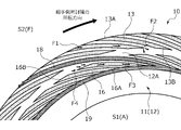
- FIG. FIG. 4 is a view of the sliding surface of the stationary seal ring in Example 1 as seen from the axial direction; 4 is an enlarged view of the sliding surface of the stationary seal ring when the rotary seal ring rotates forward in Embodiment 1, viewed from the axial direction.
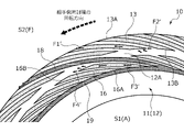
- FIG. FIG. 4 is an enlarged view of the sliding surface of the stationary seal ring when the rotary seal ring rotates in reverse in the first embodiment, as seen from the axial direction; It is the figure which looked at the sliding surface of the stationary seal ring in Example 2 of this invention from the axial direction.
- FIG. 11 is a view of the sliding surface of the stationary seal ring in Example 3 of the present invention as seen from the axial direction;
- FIG. 11 is an enlarged view of the sliding surface of the stationary seal ring when the rotary seal ring rotates forward in Embodiment 3, as seen from the axial direction;
- FIG. 11 is an enlarged view of the sliding surface of the stationary seal ring when the rotating seal ring rotates in reverse in Example 3, as seen from the axial direction;
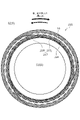
- FIG. 11 is a view of the sliding surface of the stationary seal ring in Example 4 of the present invention, viewed from the axial direction;
- FIG. 11 is a view of the sliding surface of the stationary seal ring in Example 5 of the present invention as seen from the axial direction;
- FIG. 11 is an enlarged view of the sliding surface of the stationary seal ring when the rotary seal ring rotates forward in Example 5, as seen from the axial direction;
- FIG. 12 is an enlarged view of the sliding surface of the stationary seal ring when the rotary seal ring rotates reversely in Example 5, as seen from the axial direction;
- FIG. 12 is an enlarged view of the sliding surface of the stationary seal ring in Example 6 of the present invention, viewed from the axial direction;
- FIG. 12 is an enlarged view of the sliding surface of the stationary seal ring in Example 7 of the present invention, viewed from the axial direction;
- FIG. 8 is an enlarged view of the sliding surface of the stationary seal ring of Modification 3 of Embodiment 1, viewed from the axial direction;
- FIG. 1 A mechanical seal as a sliding component according to Example 1 will be described with reference to FIGS. 1 to 4.
- FIG. In this embodiment, the atmosphere A exists in the inner space S1 of the mechanical seal, and the sealed fluid F exists in the outer space S2.
- the description will be made with the leak side (low pressure side) as a space and the outer diameter side as a sealed fluid side (high pressure side) as one space.
- dots may be attached to grooves formed on the sliding surface in the drawings.
- the automotive mechanical seal shown in FIG. 1 is of the inside type that seals the sealed fluid F in the outer space S2 that tends to leak from the outer diameter side toward the inner diameter side of the sliding surface. is open to atmosphere A.
- the sealed fluid F is a high-pressure liquid
- the atmosphere A is a gas with a pressure lower than that of the sealed fluid F.
- the mechanical seal is mainly composed of a rotating seal ring 20 as the other sliding ring and a stationary sealing ring 10 as one sliding ring.
- the rotary seal ring 20 has an annular shape and is provided on the rotary shaft 1 via the sleeve 2 so as to be rotatable together with the rotary shaft 1 .
- the stationary seal ring 10 has an annular shape and is provided in a non-rotating and axially movable state on a seal cover 5 fixed to a housing 4 of a device to which it is attached.
- the stationary seal ring 10 is axially biased by the elastic member 7 .
- the sliding surface 11 of the stationary seal ring 10 and the sliding surface 21 of the rotary seal ring 20 are designed to slide closely against each other.
- the sliding surface 21 of the rotary seal ring 20 is a flat surface, and this flat surface is not provided with recesses such as grooves.
- the stationary seal ring 10 and the rotary seal ring 20 are typically made of a combination of SiC (hard material) or SiC (hard material) and carbon (soft material). Any material that is used as a sliding material for mechanical seals can be applied.
- SiC include sintered bodies using boron, aluminum, carbon, etc. as sintering aids, and materials composed of two or more phases with different components and compositions, such as SiC and SiC in which graphite particles are dispersed.
- Metal materials, resin materials, surface modification materials (coating materials), composite materials, etc. are also applicable in addition to the sliding materials described above.
- the rotary seal ring 20 slides relative to the stationary seal ring 10 either clockwise as indicated by the solid arrow or counterclockwise as indicated by the dashed arrow. It's like In the following description, the direction indicated by the solid line arrow is the forward rotation direction of the rotary seal ring 20, and the direction indicated by the broken line arrow is the reverse rotation direction of the rotary seal ring 20. As shown in FIG.
- the sliding surface 11 of the stationary seal ring 10 is provided with a plurality of first dynamic pressure generating grooves 13, a plurality of second dynamic pressure generating grooves 16, and one conducting groove 17.
- the conducting groove 17 is composed of a plurality of communicating grooves 18 and an annular groove 19 .
- a plurality (33 in this embodiment) of the first dynamic pressure generating grooves 13 are arranged in the circumferential direction on the outer diameter side of the sliding surface 11 .
- the first dynamic pressure generating groove 13 communicates with the outer space S2 at its outer diameter side end 13A, and extends in the forward rotation direction of the rotary seal ring 20, that is, in one circumferential direction, based on the communication point.
- the first dynamic pressure generating groove 13 is a spiral groove that extends in an arcuate shape while being inclined with a clockwise component from the outer diameter side to the inner diameter side.
- the end portion 13B on the inner diameter side of the first dynamic pressure generating groove 13 has a closed shape, that is, a closed end portion.
- the first dynamic pressure generating groove 13 has a constant depth in the extending direction.
- a plurality (33 in this embodiment) of the second hydrodynamic grooves 16 are arranged in the circumferential direction on the outer diameter side of the annular groove 19 .
- the second dynamic pressure generating groove 16 communicates with the annular groove 19 at its inner diameter side end 16A, and extends in the opposite direction of rotation of the rotary seal ring 20, that is, in the other circumferential direction, based on the communication point.
- the second dynamic pressure generating groove 16 is a spiral groove that extends in an arcuate shape while being inclined with a counterclockwise component from the inner diameter side to the outer diameter side.
- the end portion 16B on the outer diameter side of the second dynamic pressure generating groove 16 has a closed shape, that is, a closed end portion.
- the second dynamic pressure generating groove 16 has a constant depth in the extending direction.
- the depth of the second dynamic pressure generating grooves 16 is the same as the depth of the first dynamic pressure generating grooves 13 .
- the inner diameter end 13B of the first dynamic pressure generating groove 13 and the outer diameter end 16B of the second dynamic pressure generating groove 16 are arranged to face each other in the radial direction with a land 12A, which will be described later, interposed therebetween. .
- a plurality (three in this embodiment) of the communication grooves 18 are evenly arranged in the circumferential direction on the outer diameter side of the sliding surface 11 .
- the communication groove 18 communicates with the outer space S2, and extends in an arc shape from the outer diameter side toward the inner diameter side while being inclined with a clockwise component.
- the communication groove 18 extends substantially parallel to the first dynamic pressure generating groove 13 and the second dynamic pressure generating groove 16 when viewed from the axial direction. In other words, the communication groove 18 extends so as not to cross the first dynamic pressure generating groove 13 and the second dynamic pressure generating groove 16 .
- the communication groove 18 is formed to be longer in the extension direction than the first dynamic pressure generating groove 13 .
- a predetermined number (11 each in this embodiment) of the first dynamic pressure generating grooves 13 and the second dynamic pressure generating grooves 16 are arranged between the communicating grooves 18 adjacent to each other in the circumferential direction.
- the communication groove 18 has a constant depth in the extending direction.
- the communication groove 18 is formed deeper than the first dynamic pressure generating groove 13 and the second dynamic pressure generating groove 16 .
- the annular groove 19 is formed in an annular shape when viewed in the axial direction, and the inner diameter side end of each communication groove 18 communicates with the annular groove 19 . In other words, the annular groove 19 communicates with the outer space S2 through each communication groove 18 .
- the annular groove 19 has a constant depth in the circumferential direction. Incidentally, in this embodiment, the depth of the annular groove 19 is the same as the depth of the communication groove 18 .
- the portions of the sliding surface 11 other than the first dynamic pressure generating groove 13, the second dynamic pressure generating groove 16, the communicating groove 18, and the annular groove 19 form lands 12 having a flat surface arranged on the same plane.
- the flat surface of the land 12 functions as a sliding surface that substantially slides on the sliding surface 21 of the rotary seal ring 20 .
- the land 12 includes a land between the first dynamic pressure generating grooves 13 adjacent in the circumferential direction, a land between the first dynamic pressure generating groove 13 and the communication groove 18 adjacent in the circumferential direction, and The first dynamic pressure generating grooves 13 radially separated from the land between the adjacent second dynamic pressure generating grooves 16 and the land between the second dynamic pressure generating groove 16 and the communication groove 18 adjacent in the circumferential direction. and the second hydrodynamic groove 16 extending in the circumferential direction, and an annular land on the inner diameter side of the annular groove 19. These lands are arranged in the same plane. It is arranged and constitutes the flat surface of the land 12 .
- the sealed fluid F flows into the first dynamic pressure generating groove 13 from the opening of the end portion 13A and also flows from the opening of the communicating groove 18 on the outer diameter side. It flows into the second hydrodynamic groove 16 through the communication groove 18 and the annular groove 19 . Since the stationary seal ring 10 is urged toward the rotary seal ring 20 by the elastic member 7, the sliding surfaces 11 and 21 are in contact with each other, and the fluid F to be sealed between the sliding surfaces 11 and 21 is kept in contact with each other. There is almost no amount of leaking into the inner space S1.
- the sealed fluid F moves from the opening of the outer diameter side end portion 13A toward the inner diameter side end portion 13B as indicated by the arrow F1. This increases the pressure at and near the end 13B. That is, a positive pressure is generated at the end portion 13B of the first dynamic pressure generating groove 13 and the land 12A in the vicinity thereof.
- the sliding surfaces 11 and 21 are slightly separated from each other due to the positive pressure generated at the end 13B of the first dynamic pressure generating groove 13 and the land 12A in the vicinity thereof (not shown). Specifically, the absolute value of the positive pressure generated by the first dynamic pressure generating grooves 13 is greater than the absolute value of the negative pressure generated by the second dynamic pressure generating grooves 14, which will be described later.
- the sealed fluid F in the first dynamic pressure generating groove 13 flows between the sliding surfaces 11 and 21 as shown mainly by the arrow F2.
- the sealed fluid F between the sliding surfaces 11 and 21 in this manner, lubricity is improved even during low-speed rotation, and wear between the sliding surfaces 11 and 21 can be suppressed. Since the floating distance between the sliding surfaces 11 and 21 is small, the amount of the sealed fluid F that leaks into the outer space S2 is small.
- the sealed fluid F in the communicating groove 18 and the annular groove 19 also flows between the sliding surfaces 11 and 21 . Therefore, the sealed fluid F efficiently flows between the sliding surfaces 11 and 21 .
- the sealed fluid F moves from the outer diameter side end 16B toward the inner diameter side end 16A as indicated by an arrow F3.
- the fluid pressure near the end 16B is relatively lower than the surrounding fluid pressure.
- a relative negative pressure is generated in the vicinity of the end portion 16B, and the sealed fluid F between the sliding surfaces 11 and 21 is sucked into the second dynamic pressure generating groove 16 as indicated by the arrow F4.
- the sealed fluid F sucked into the second dynamic pressure generating groove 16 is recovered into the annular groove 19 .
- the annular groove 19 communicates with the outer space S2 through the communication groove 18 so that the sealed fluid F can be taken in and out. Therefore, when more sealed fluid F than the amount that can be stored in the annular groove 19 is recovered, excess sealed fluid F is returned to the outer space S2.
- the sealed fluid F moves from the radially inner end 13B toward the opening of the radially outer end 13A as indicated by an arrow F1'.
- the fluid pressure near the end 13B is relatively lower than the surrounding fluid pressure.
- a relative negative pressure is generated near the end 13B, and the sealed fluid F between the sliding surfaces 11 and 21 is sucked into the first dynamic pressure generating groove 13 as indicated by arrow F2'.
- the sealed fluid F sucked into the first dynamic pressure generating groove 13 is returned to the outer space S2 through the opening of the end portion 13A on the outer diameter side.
- the sealed fluid F moves from the inner diameter side end 16A toward the outer diameter side end 16B as indicated by an arrow F3'. This increases the pressure at and near end 16B. That is, a positive pressure is generated at the end portion 16B of the second dynamic pressure generating groove 16 and the land 12A in the vicinity thereof.
- the sliding surfaces 11 and 21 are slightly separated from each other due to the positive pressure generated at the end 16B of the second dynamic pressure generating groove 16 and the land 12A in the vicinity thereof (not shown). Specifically, the absolute value of the positive pressure generated by the second dynamic pressure generating grooves 14 is greater than the absolute value of the negative pressure generated by the above-described first dynamic pressure generating grooves 13 . As a result, the sealed fluid F in the second dynamic pressure generating groove 16 flows between the sliding surfaces 11 and 21 as indicated by an arrow F4'.
- the sealed fluid F in the outer space S2 flows from the end 13B of the first dynamic pressure generating groove 13 to the sliding surface. 11 and 21 are supplied.
- the sealed fluid F in the outer space S2 flows from the end 16B of the second hydrodynamic groove 16 through the communication groove 18 and the annular groove 19. It is supplied between the sliding surfaces 11 and 21 . Therefore, the lubricity between the sliding surfaces 11 and 21 is good in either direction of relative rotation.
- a land 12 ⁇ /b>A extending in the circumferential direction is provided between the first dynamic pressure generating groove 13 and the second dynamic pressure generating groove 16 . According to this, the positive pressure generated at the end portion 13B of the first dynamic pressure generating groove 13 and the end portion 16B of the second dynamic pressure generating groove 16 is generated at the same land 12A. The separated state between the sliding surfaces 11 and 21 is almost the same.
- the end portion 13B of the first dynamic pressure generating groove 13 and the end portion 16B of the second dynamic pressure generating groove 16 face each other in the radial direction with the land 12A interposed therebetween. According to this, when the rotary seal ring 20 rotates in the positive direction relative to the stationary seal ring 10, the sealed pressure supplied between the sliding surfaces 11 and 21 from the end portion 13B of the first dynamic pressure generating groove 13 is applied. The fluid F is efficiently recovered at the ends 16B of the second dynamic pressure generating grooves 16 arranged opposite to each other.
- the sealed fluid F supplied between the sliding surfaces 11 and 21 from the end portion 16B of the second dynamic pressure generating groove 16 is It is efficiently recovered at the ends 13B of the first dynamic pressure generating grooves 13 arranged opposite to each other. This prevents the positive pressure from becoming too high regardless of the speed of the relative rotation.
- the conduction groove 17 is composed of an annular groove 19 and a communication groove 18 that communicates the annular groove 19 with the outer space S2. According to this, since the annular groove 19 is arranged closer to the inner space S1 than the first dynamic pressure generating groove 13 and the second dynamic pressure generating groove 16, the annular groove 19 slides from the outer space S2 toward the inner space S1. The sealed fluid F flowing between the surfaces 11 and 21 can be recovered reliably. Further, since the annular groove 19 can store a large amount of the sealed fluid F, the sealed fluid F is reliably supplied to the second dynamic pressure generating groove 16 .
- a plurality of communication grooves 18 are provided in the circumferential direction of the annular groove 19 . Thereby, the sealed fluid F is efficiently introduced or discharged from the plurality of communication grooves 18 .
- the sealed fluid F since a large amount of the sealed fluid F exists in the communication groove 18, which is a deep groove, the sealed fluid F is easily supplied between the sliding surfaces 11 and 21 slightly spaced apart due to the relative rotation.
- first dynamic pressure generating groove 13 and the second dynamic pressure generating groove 16 are spiral grooves extending radially while being inclined in the circumferential direction. According to this, the first dynamic pressure generating grooves 13 and the second dynamic pressure generating grooves 16 can be densely arranged in the circumferential direction. In other words, the stationary seal ring 10 has a high degree of freedom in design.
- the communication groove 18 extends so as not to cross the first dynamic pressure generating groove 13 and the second dynamic pressure generating groove 16 .
- the communicating groove 18 is not arranged across the land 12A between the end 13B of the first dynamic pressure generating groove 13 and the end 16B of the second dynamic pressure generating groove 16, the first dynamic pressure generating groove 13 and It does not interfere with the generation of dynamic pressure in the second dynamic pressure generating grooves 16 .
- the communication groove 18 extends parallel to the first dynamic pressure generating groove 13 and the second dynamic pressure generating groove 16
- the first dynamic pressure generating groove 13 and the second dynamic pressure generating groove 16 extend further in the circumferential direction. can be densely arranged.
- the stationary seal ring 210 in the mechanical seal of the second embodiment differs from the stationary seal ring 10 of the first embodiment in the configuration of the conducting groove, and the rest of the configuration is the same as that of the stationary seal ring 10 of the first embodiment.
- the conducting groove 217 of the stationary seal ring 210 is composed of a communicating groove 218 and an arcuate groove 219. As shown in FIG. The arcuate groove 219 extends circumferentially concentrically with the stationary seal ring 210 in the clockwise direction from the inner diameter side end of the communicating groove 218 . A plurality (three in this embodiment) of the conductive grooves 217 are provided in the circumferential direction.
- each second dynamic pressure generating groove 16 communicates with the arcuate groove 219 .
- a stationary seal ring 310 in the mechanical seal of the third embodiment differs from the stationary seal ring 10 of the first embodiment in the configuration of the first dynamic pressure generating groove and the second dynamic pressure generating groove. It has the same configuration as the stationary seal ring 10 .
- the sliding surface 311 of the stationary seal ring 310 includes a plurality of first dynamic pressure generating mechanisms 313, a plurality of communication grooves 18, an annular groove 19, and a plurality of second dynamic pressure generating mechanisms.
- a mechanism 316 is provided.
- the first dynamic pressure generating mechanism 313 is composed of a first deep groove 313A and a first Rayleigh step 313B as the first dynamic pressure generating groove.
- the end of the first deep groove 313A on the outer diameter side communicates with the outer space S2 and extends in the inner diameter direction.
- the first deep groove 313A is formed slightly shallower than the communication groove 18 and the annular groove 19. As shown in FIG.
- the first Rayleigh step 313B extends circumferentially concentrically with the stationary seal ring 310 clockwise from the inner diameter side of the first deep groove 313A.
- the first Rayleigh step 313B is formed shallower than the first deep groove 313A.
- the second dynamic pressure generating mechanism 316 is composed of a second deep groove 316A and a second Rayleigh step 316B as a second dynamic pressure generating groove.
- the end of the second deep groove 316A on the inner diameter side communicates with the annular groove 19 and extends in the outer diameter direction.
- the second deep groove 316 ⁇ /b>A is formed slightly shallower than the communication groove 18 and the annular groove 19 .
- the second deep groove 316A is formed to the same depth as the first deep groove 313A.
- the second Rayleigh step 316B extends circumferentially concentrically with the stationary seal ring 310 counterclockwise from the outer diameter side of the second deep groove 316A.
- the second Rayleigh step 316B is shallower than the second deep groove 316A.
- the second Rayleigh step 316B is formed to the same depth as the first Rayleigh step 313B.
- first deep groove 313A and the second deep groove 316A are formed slightly shallower than the communication groove 18 and the annular groove 19 in the third embodiment, they may be formed to the same depth. Also, the first deep groove 313A and the second deep groove 316A may be formed to the same depth as the first Rayleigh step 313B and the second Rayleigh step 316B.
- first deep groove 313A and the second deep groove 316A are formed to the same depth in the third embodiment, they may be formed to different depths.
- first Rayleigh step 313B and the second Rayleigh step 316B are formed to the same depth in the third embodiment, they may be formed to different depths.
- the sealed fluid F in the first deep groove 313A moves from the communicating portion between the first deep groove 313A and the first Rayleigh step 313B as indicated by the arrow F10 to the first Move toward the closed end 313a of the Rayleigh step 313B.
- a positive pressure is generated at the closed end 313a of the first Rayleigh step 313B and its vicinity, and the sliding surfaces 311 and 21 are separated from each other, and the sealed fluid F is pushed to the sliding surfaces as indicated by an arrow F11. It flows between 311 and 21.
- the sealed fluid F in the second Rayleigh step 316B moves toward the second deep groove 316A as indicated by the arrow F12.
- a relative negative pressure is generated in the vicinity of the closed end 316a of the second Rayleigh step 316B, and the sealed fluid F between the sliding surfaces 311 and 21 is pushed into the second Rayleigh step 316B as indicated by an arrow F13. sucked into.
- the sealed fluid F within the first Rayleigh step 313B moves toward the first deep groove 313A as indicated by the arrow F10'.
- a relative negative pressure is generated in the closed end portion 313a of the first Rayleigh step 313B and its vicinity, and the sealed fluid F between the sliding surfaces 311 and 21 moves toward the first Rayleigh step 313B as indicated by an arrow F11'. Sucked into 313B.
- the sealed fluid F in the second deep groove 316A flows from the communication portion between the second deep groove 316A and the second Rayleigh step 316B as indicated by the arrow F12'. 2 Move toward the closed end 316a of the Rayleigh step 316B. As a result, a positive pressure is generated at the closed end 316a of the second Rayleigh step 316B and its vicinity, and the sliding surfaces 311 and 21 are separated from each other, and the sealed fluid F slides as indicated by the arrow F13'. It flows between the surfaces 311 and 21 .
- both lubricity and sealing between the sliding surfaces 311 and 21 can be achieved regardless of the relative rotation direction of the rotary seal ring 20 .
- the mechanical seal of the fourth embodiment is an outside type in which the sealed fluid F exists in the inner space S1 and the atmosphere A exists in the outer space S2.
- the inner space S1 functions as a space on one side
- the outer space S2 functions as a space on the other side.
- a stationary seal ring 410 in the mechanical seal of the fourth embodiment is provided with a plurality of first dynamic pressure generating grooves 413, a plurality of communicating grooves 418, an annular groove 419, and a plurality of second dynamic pressure generating grooves 416. It is A plurality of communicating grooves 418 and annular groove 419 constitute one conducting groove 417 .
- the first dynamic pressure generating groove 413 communicates with the inner space S1 at its inner diameter side end 413B, and extends in the forward rotation direction of the rotary seal ring 20, that is, in one circumferential direction, based on the communication point. More specifically, the first dynamic pressure generating groove 413 is a spiral groove that extends in an arc shape from the inner diameter side to the outer diameter side while being inclined with a clockwise component. Further, the outer diameter side end portion 413A of the first dynamic pressure generating groove 413 has a closed shape, that is, a closed end portion.
- the communication groove 418 communicates with the inner space S1, and extends in an arc shape from the inner diameter side toward the outer diameter side while being inclined with a clockwise component.
- each communication groove 418 communicates with the annular groove 419 .
- the annular groove 419 communicates with the inner space S ⁇ b>1 through each communication groove 418 .
- the second dynamic pressure generating groove 416 communicates with the annular groove 419 at its outer diameter side end 416B, and extends in the opposite direction of rotation of the rotary seal ring 20, that is, in the other circumferential direction, based on the communication point.
- the second dynamic pressure generating groove 416 is a spiral groove that extends in an arcuate shape while being inclined with a counterclockwise component from the outer diameter side to the inner diameter side.
- an end portion 416A on the inner diameter side of the second dynamic pressure generating groove 416 has a closed shape, that is, a closed end portion.
- Examples 2 and 3 may also be arranged on the inner diameter side to form an outside type. Further, in Examples 4, 5 and 6, and Modifications 1, 2 and 3 of Example 1, which will be described later, grooves may be arranged on the inner diameter side to form an outside type.
- a stationary seal ring 510 in the mechanical seal of the fifth embodiment differs from the stationary seal ring 10 of the first embodiment in that a third dynamic pressure generating groove 530 is provided. It has the same configuration as the ring 10 .
- the sliding surface 511 of the stationary seal ring 510 is provided on the inner diameter side of the annular groove 19, that is, at a position where the first dynamic pressure generating groove 13 and the second dynamic pressure generating groove 16 are not provided.
- a plurality of (36 in this embodiment) third dynamic pressure generating grooves 530 are provided in the circumferential direction.
- the third dynamic pressure generating groove 530 is a curved groove whose outer diameter side end communicates with the annular groove 19 .
- the third dynamic pressure generating groove 530 has a first inclined groove portion 531 and a second inclined groove portion 532 .
- the third hydrodynamic groove 530 has a constant depth in the extending direction.
- the third dynamic pressure generating grooves 530 have the same depth as the first dynamic pressure generating grooves 13 and the second dynamic pressure generating grooves 16, they may be formed to different depths.
- the first inclined groove portion 531 extends in the inner diameter direction while being inclined in the reverse rotation direction of the rotary seal ring 20, that is, in the other direction of the circumferential direction, with reference to the communicating portion with the annular groove 19.
- the second inclined groove portion 532 communicates with the inner diameter side end portion of the first inclined groove portion 531, and extends in the inner diameter direction while being inclined in the forward rotation direction of the rotary seal ring 20, that is, in one direction in the circumferential direction with respect to the communication point.
- the third dynamic pressure generating groove 530 is composed of a side surface 531a positioned in the reverse rotation direction that defines the first inclined groove portion 531, and a side surface 532a positioned in the reverse rotation direction that defines the second inclined groove portion 532. It has a corner portion 530a.
- one second inclined groove portion 532 is arranged on the inner diameter side of the corner portion 530a of the third dynamic pressure generating groove 530 adjacent in the forward rotation direction. Further, the second inclined groove portion 532 is longer than the first inclined groove portion 531 in the extending direction. In addition, the closed end of the second inclined groove portion 532 is arranged closer to the forward rotation direction than the corner portion 530a of the third dynamic pressure generating groove 530 adjacent thereto in the forward rotation direction.
- the sealed fluid F moves in the first dynamic pressure generating groove 13 as indicated by an arrow F1.
- the sealed fluid F in the first dynamic pressure generating groove 13 flows into between the sliding surfaces 511 and 21 as indicated by an arrow F2.
- the sealed fluid F moves as indicated by arrow F3
- the sealed fluid F between the sliding surfaces 511 and 21 moves second as indicated by arrow F4. It is sucked into the pressure generating groove 16 .
- the sealed fluid F moves toward the annular groove 19 as indicated by the arrow F5
- the sealed fluid F moves toward the annular groove 19.
- the sealing fluid F moves toward the inner closed end as indicated by arrow F6.
- the sealed fluid F in the first inclined groove portion 531 moves toward the annular groove 19, and the sealed fluid F in the second inclined groove portion 532 is discharged between the sliding surfaces 511 and 21. . Therefore, the third dynamic pressure generating groove 530 has a relatively negative pressure, and a cavitation region C is formed in the vicinity of the third dynamic pressure generating groove 530 over the circumferential direction (see the hatched portion in FIG. 11). Incidentally, the hatched portion in FIG. 11 indicates the cavitation region C, which is shown more emphasized than it actually is.
- the sealed fluid F does not move toward the inner diameter side of the annular groove 19. is suppressed.
- the sealed fluid F can be prevented from leaking into the inner space S1, and the sealing performance between the sliding surfaces 511 and 21 can be supplementarily improved.
- the third dynamic pressure generating groove 530 has a component extending in the radial direction, a large radial width of the cavitation region C can be secured, and the sealed fluid F is less likely to leak into the inner space S1.
- the sealed fluid F flows in the first dynamic pressure generating groove 13 as indicated by an arrow F1'.
- the sealed fluid F between the sliding surfaces 511 and 21 is sucked into the first dynamic pressure generating groove 13 as indicated by an arrow F2'.
- the sealed fluid F moves as indicated by arrow F3', and the second fluid flow between the sliding surfaces 11 and 21 mainly indicates by arrow F4'.
- the sealed fluid F in the dynamic pressure generating groove 16 flows.
- the sealed fluid F moves from the annular groove 19 toward the corner portion 530a as indicated by the arrow F5' and moves toward the second inclined groove portion 530a.
- the sealed fluid F moves from the closed end on the inner diameter side toward the corner portion 530a as indicated by an arrow F6'.
- the sealed fluid F concentrates at and near the corner 530a to generate a positive pressure, and between the sliding surfaces 511 and 21, a third dynamic pressure is generated as shown mainly by an arrow F7.
- the sealed fluid F in the groove 530 flows.
- the lubricity between the sliding surfaces 511 and 21 can be supplementarily improved.
- one second inclined groove portion 532 is arranged on the inner diameter side of the corner portion 530a of the third dynamic pressure generating groove 530 adjacent in the forward rotation direction, the contact between the corner portion 530a and the sliding surfaces 511 and 21 The sealed fluid F that has flowed out is collected in one second inclined groove portion 532 and is less likely to leak into the inner space S1.
- the corner portion 530a of the third hydrodynamic groove 530 can be arranged closer to the annular groove 19.
- the corner portion 530a can be arranged away from the inner space S1
- the sealed fluid F flowing out between the sliding surfaces 511 and 21 from the corner portion 530a reaches the second inclined groove portion 532 and the inner space S1.
- the sealed fluid F is easily collected in the annular groove 19, and the sealed fluid F is less likely to leak into the inner space S1.
- a stationary seal ring 610 in the mechanical seal of the sixth embodiment differs from the stationary seal ring 10 of the first embodiment in that a third dynamic pressure generating groove 630 is provided. It has the same configuration as the ring 10 .
- the sliding surface 611 of the stationary seal ring 610 is provided with a plurality of third dynamic pressure generating grooves 630 in the circumferential direction on the inner diameter side of the annular groove 19 .
- the third dynamic pressure generating groove 630 communicates with the annular groove 19 and extends in the radial direction while being inclined in the opposite direction of rotation of the rotary seal ring 20, that is, in the other circumferential direction, with reference to the communicating portion.
- the third dynamic pressure generating groove 630 of the sixth embodiment extends radially inward from the connecting portion of the annular groove 19 while being inclined in the reverse rotation direction of the rotary seal ring 20
- the annular groove 19 may extend in the inner diameter direction while being inclined in the forward rotation direction of the rotary seal ring 20 from the communicating portion of the rotary seal ring 20 .
- a stationary seal ring 710 in the mechanical seal of the seventh embodiment differs from the stationary seal ring 10 of the first embodiment in that a third dynamic pressure generating groove 730 is provided. It has the same configuration as the ring 10 .
- the sliding surface 711 of the stationary seal ring 710 is provided with a plurality of third dynamic pressure generating grooves 730 in the circumferential direction on the inner diameter side of the annular groove 19 .
- the third dynamic pressure generating groove 730 is a dimple having a circular shape when viewed in the axial direction.
- the third dynamic pressure generating groove 730 is not limited to a circular shape when viewed in the axial direction, and may be a long hole such as a rectangular or elliptical shape when viewed in the axial direction.
- Example 1 to 7 an example in which the first dynamic pressure generating groove and the second dynamic pressure generating groove are provided in the stationary seal ring has been described, but the first dynamic pressure generating groove and the second dynamic pressure generating groove are rotated. It may be provided in the seal ring, or the first dynamic pressure generating groove and the second dynamic pressure generating groove may be provided in the stationary seal ring and the rotary seal ring, respectively, or both.
- Examples 1 to 7 examples in which the communicating groove and the annular groove are provided in the stationary seal ring have been described, but the communicating groove and the annular groove may be provided in the rotary seal ring, or the communicating groove and the annular groove may be provided in the rotary seal ring. may be provided on the stationary seal ring and the rotary seal ring, respectively, or both.
- the sealed fluid side is assumed to be the high pressure side and the leak side is assumed to be the low pressure side, but the sealed fluid side and the leak side may have substantially the same pressure.
- the sealed fluid F is described as a high-pressure liquid, but it is not limited to this, and may be a gas or a mist-like mixture of a liquid and a gas.
- the fluid on the leak side is explained to be the atmosphere A, which is a low-pressure gas. It may be in the form of a mist.
- the first dynamic pressure generating groove and the second dynamic pressure generating groove are curved and extended, but the first dynamic pressure generating groove and the second dynamic pressure generating groove It may extend linearly.
- the first dynamic pressure generating groove and the second dynamic pressure generating groove have a constant depth.
- it may be formed in a stepped shape.
- the communicating grooves forming the conducting grooves were exemplified as extending in the radial direction while being inclined in the circumferential direction.
- the communication groove 818 extends linearly in the radial direction, and may communicate the annular groove 19 and the outer space S2.
- a land extending in the circumferential direction is provided between the first dynamic pressure generating groove and the second dynamic pressure generating groove, and the closed ends face each other in the radial direction.
- the first dynamic pressure generating grooves 13 and the second dynamic pressure generating grooves 16 may be alternately arranged in the circumferential direction like the stationary seal ring 910 of Modified Example 2 shown in FIG.
- the closed end of the first dynamic pressure generating groove 13 may be arranged closer to the annular groove 19 than the closed end of the second dynamic pressure generating groove 16 .
- the communicating groove is formed on the sliding surface. It may extend in the inner diameter direction from the outer peripheral surface of 100 , and the inner diameter end may be configured to extend in the axial direction and communicate with the annular groove 19 .
- the sealed fluid F does not flow into or out of the sliding surface from the communicating groove 180, and the first dynamic pressure generating grooves 13 and the second dynamic pressure generating grooves 14 are evenly arranged in the circumferential direction. From these, dynamic pressure is generated uniformly in the circumferential direction.
- the stationary seal ring is provided with a plurality of first dynamic pressure generating grooves and second dynamic pressure generating grooves having the same shape in the circumferential direction.
- the ring may have, for example, a mixture of spiral grooves as in Example 1 and Rayleigh steps as in Example 3.
Landscapes
- Engineering & Computer Science (AREA)
- General Engineering & Computer Science (AREA)
- Mechanical Engineering (AREA)
- Physics & Mathematics (AREA)
- Fluid Mechanics (AREA)
- Chemical & Material Sciences (AREA)
- Oil, Petroleum & Natural Gas (AREA)
- Mechanical Sealing (AREA)
Abstract
Description
回転機械の駆動時に相対回転する箇所に対向して配置される一対の摺動面を備える摺動部品であって、
一方の摺動面には、内径側空間および外径側空間の一側の空間に連通して周方向一方に延びる第1動圧発生溝と、周方向他方に延びる第2動圧発生溝と、前記一側の空間に連通する導通溝と、が設けられており、
前記第2動圧発生溝は前記導通溝よりも一側の空間に配置されかつ前記導通溝に連通している。
これによれば、回転機械の駆動時における周方向一方向への相対回転において、一側の空間の流体は、第1動圧発生溝の閉塞端部から摺動面間に供給される。また、回転機械の駆動時における周方向他方向への相対回転において、一側の空間の流体は導通溝を通じて第2動圧発生溝の閉塞端部から摺動面間に供給される。そのため、いずれの相対回転方向であっても、摺動面間の潤滑性が良好である。
これによれば、第1動圧発生溝及び第2動圧発生溝により生じる正圧は同じランドで発生するため、いずれの相対回転方向であっても摺動面同士の離間状態はほぼ同じとなる。
これによれば、一方の動圧発生溝から摺動面間に供給された流体は対向配置された他方の動圧発生溝で効率よく回収される。
これによれば、環状溝は、摺動面間を一側の空間から他側の空間に向けて流れる流体を確実に回収できる。また、環状溝は、多くの流体を貯留可能であることから、第2動圧発生溝に流体が確実に供給される。
これによれば、第1動圧発生溝および第2動圧発生溝は周方向に密に配置され得る。
これによれば、連通溝が第1動圧発生溝および第2動圧発生溝の動圧の発生に干渉することがない。
これによれば、前記導通溝よりも他側の空間側のスペースに第3動圧発生溝を設けられていることから、第3動圧発生溝で生じる動圧により摺動面間の潤滑性や密封性は更に高められている。
これによれば、摺動面の相対回転方向に応じて第3動圧発生溝の動圧の状態は変化する。
2 スリーブ
4 ハウジング
10 静止密封環
11 摺動面
12A ランド
13 第1動圧発生溝(スパイラル溝)
13A 端部(閉塞端部)
13B 端部
16 第2動圧発生溝(スパイラル溝)
16B 端部(閉塞端部)
17 導通溝
18 連通溝
19 環状溝
20 回転密封環
21 摺動面
313B 第1レイリーステップ(第1動圧発生溝)
316B 第2レイリーステップ(第2動圧発生溝)
530 第3動圧発生溝
A 大気
C キャビテーション領域
F 被密封流体
S1 内空間(他側の空間)
S2 外空間(一側の空間)
Claims (8)
- 回転機械の駆動時に相対回転する箇所に対向して配置される一対の摺動面を備える摺動部品であって、
一方の摺動面には、内径側空間および外径側空間の一側の空間に連通して周方向一方に延びる第1動圧発生溝と、周方向他方に延びる第2動圧発生溝と、前記一側の空間に連通する導通溝と、が設けられており、
前記第2動圧発生溝は前記導通溝よりも一側の空間に配置されかつ前記導通溝に連通している摺動部品。 - 前記第1動圧発生溝と前記第2動圧発生溝との間には、周方向に延びるランドが設けられている請求項1に記載の摺動部品。
- 前記第1動圧発生溝の閉塞端部および前記第2動圧発生溝の閉塞端部は径方向に対向している請求項2に記載の摺動部品。
- 前記導通溝は、環状溝と、該環状溝と前記一側の空間を連通する連通溝と、を有している請求項1に記載の摺動部品。
- 前記第1動圧発生溝および前記第2動圧発生溝はスパイラル溝である請求項1に記載の摺動部品。
- 前記連通溝は、前記第1動圧発生溝および前記第2動圧発生溝と交差しないように延びている請求項5に記載の摺動部品。
- 前記一対の摺動面における前記導通溝よりも他側の空間側には、第3動圧発生溝が設けられている請求項1ないし6のいずれかに記載の摺動部品。
- 前記第3動圧発生溝は前記導通溝に連通された屈曲溝である請求項7に記載の摺動部品。
Priority Applications (5)
| Application Number | Priority Date | Filing Date | Title |
|---|---|---|---|
| JP2023535217A JP7749888B2 (ja) | 2021-07-13 | 2022-06-28 | 摺動部品 |
| CN202280046968.0A CN117642568A (zh) | 2021-07-13 | 2022-06-28 | 滑动部件 |
| KR1020247000696A KR20240019290A (ko) | 2021-07-13 | 2022-06-28 | 슬라이딩 부품 |
| US18/575,663 US12473946B2 (en) | 2021-07-13 | 2022-06-28 | Sliding components |
| EP22841934.7A EP4372253A4 (en) | 2021-07-13 | 2022-06-28 | SLIDING ELEMENTS |
Applications Claiming Priority (2)
| Application Number | Priority Date | Filing Date | Title |
|---|---|---|---|
| JP2021-115873 | 2021-07-13 | ||
| JP2021115873 | 2021-07-13 |
Publications (1)
| Publication Number | Publication Date |
|---|---|
| WO2023286590A1 true WO2023286590A1 (ja) | 2023-01-19 |
Family
ID=84919997
Family Applications (1)
| Application Number | Title | Priority Date | Filing Date |
|---|---|---|---|
| PCT/JP2022/025794 Ceased WO2023286590A1 (ja) | 2021-07-13 | 2022-06-28 | 摺動部品 |
Country Status (6)
| Country | Link |
|---|---|
| US (1) | US12473946B2 (ja) |
| EP (1) | EP4372253A4 (ja) |
| JP (1) | JP7749888B2 (ja) |
| KR (1) | KR20240019290A (ja) |
| CN (1) | CN117642568A (ja) |
| WO (1) | WO2023286590A1 (ja) |
Families Citing this family (2)
| Publication number | Priority date | Publication date | Assignee | Title |
|---|---|---|---|---|
| US12404936B2 (en) * | 2021-09-28 | 2025-09-02 | Eagle Indusry Co., Ltd. | Sliding component |
| KR20250008107A (ko) * | 2022-05-19 | 2025-01-14 | 이구루코교 가부시기가이샤 | 슬라이딩 부품 |
Citations (5)
| Publication number | Priority date | Publication date | Assignee | Title |
|---|---|---|---|---|
| JPH0666374A (ja) * | 1992-04-02 | 1994-03-08 | John Crane Inc | 二重螺旋溝を有する面シール |
| WO2012046749A1 (ja) * | 2010-10-06 | 2012-04-12 | イーグル工業株式会社 | 摺動部品 |
| WO2014174725A1 (ja) * | 2013-04-24 | 2014-10-30 | イーグル工業株式会社 | 摺動部品 |
| WO2016035860A1 (ja) * | 2014-09-04 | 2016-03-10 | イーグル工業株式会社 | メカニカルシール |
| WO2020162025A1 (ja) | 2019-02-04 | 2020-08-13 | イーグル工業株式会社 | 摺動部品 |
Family Cites Families (152)
| Publication number | Priority date | Publication date | Assignee | Title |
|---|---|---|---|---|
| JPS366305B1 (ja) | 1960-03-31 | 1961-05-30 | ||
| US3085808A (en) * | 1960-05-17 | 1963-04-16 | Worthington Corp | Mechanical seal with controlled leakage |
| US3232680A (en) * | 1963-08-19 | 1966-02-01 | Whittaker Corp | Fluid bearing |
| NL143660B (nl) * | 1965-03-27 | 1974-10-15 | Philips Nv | Axiaal leger. |
| US3410565A (en) * | 1966-07-27 | 1968-11-12 | Worthington Corp | Centrifugal and face contact seal |
| FR1505487A (fr) * | 1966-10-28 | 1967-12-15 | Guinard Pompes | Perfectionnement aux joints tournants à régulation de fuite |
| US3466052A (en) * | 1968-01-25 | 1969-09-09 | Nasa | Foil seal |
| US3499653A (en) * | 1968-06-05 | 1970-03-10 | Crane Packing Co | Rotary mechanical seal of the gap type |
| US3656227A (en) * | 1970-03-26 | 1972-04-18 | Gen Motors Corp | Method of making a mold for bidirectional hydrodynamic shaft seals |
| US3804424A (en) * | 1972-04-24 | 1974-04-16 | Crane Packing Co | Gap seal with thermal and pressure distortion compensation |
| JPS4933614A (ja) | 1972-07-24 | 1974-03-28 | ||
| JPS5477305A (en) | 1977-12-02 | 1979-06-20 | Hitachi Constr Mach Co Ltd | Compound pump motor |
| JPS57146955A (en) | 1981-03-06 | 1982-09-10 | Shinsaku Kaguchi | Sealing device for rotary member |
| JPS58109771A (ja) | 1981-12-23 | 1983-06-30 | Eagle Ind Co Ltd | 非接触型メカニカルシ−ル |
| JPS58137667A (ja) | 1982-02-10 | 1983-08-16 | Nippon Seiko Kk | 磁性流体シ−ル |
| US4486026A (en) * | 1982-02-10 | 1984-12-04 | Nippon Seiko K.K. | Sealing and bearing means by use of ferrofluid |
| JPS5958252A (ja) | 1982-09-29 | 1984-04-03 | Honda Motor Co Ltd | Vベルト伝動装置 |
| US4406466A (en) * | 1982-11-29 | 1983-09-27 | Elliott Turbomachinery Co., Inc. | Gas lift bearing and oil seal |
| JPS60107461A (ja) | 1983-11-15 | 1985-06-12 | Jidosha Kiki Co Ltd | 動力舵取装置の制御方法 |
| JPH06100642B2 (ja) | 1984-09-29 | 1994-12-12 | 株式会社東芝 | 光応用磁界センサ |
| JPS6237572A (ja) | 1985-08-12 | 1987-02-18 | Ebara Res Co Ltd | 軸封装置 |
| DE3619489A1 (de) | 1986-06-10 | 1987-12-17 | Gutehoffnungshuette Man | Wellendichtung |
| JPS6333027A (ja) | 1986-07-28 | 1988-02-12 | Nippon Hoso Kyokai <Nhk> | 音声デジタル信号伝送方式 |
| CH677266A5 (ja) * | 1986-10-28 | 1991-04-30 | Pacific Wietz Gmbh & Co Kg | |
| JPH01133572A (ja) | 1987-11-16 | 1989-05-25 | Sanyo Electric Co Ltd | 単相周波数変換回路 |
| JPH06105105B2 (ja) | 1989-03-03 | 1994-12-21 | 日本ピラー工業株式会社 | 端面非接触形メカニカルシール |
| JPH0314371A (ja) | 1989-06-13 | 1991-01-23 | Fuji Photo Film Co Ltd | ビデオカメラの映像動揺補正装置 |
| JPH0335372A (ja) | 1989-06-30 | 1991-02-15 | Mita Ind Co Ltd | 画像判別装置 |
| JP2554542B2 (ja) | 1989-07-06 | 1996-11-13 | 株式会社 藤井合金製作所 | ガスコックの製造方法 |
| JPH0341267A (ja) | 1989-07-07 | 1991-02-21 | Mitsuwa Gas Kiki Kk | 鋳鉄製ガスコックの製造方法 |
| JPH03108972A (ja) | 1989-09-22 | 1991-05-09 | Fuji Photo Film Co Ltd | 映像信号の記録方法 |
| JPH0660691B2 (ja) | 1990-04-17 | 1994-08-10 | イーグル工業株式会社 | 両回転式準接触メカニカルシール及びリング摺動面の溝加工方法 |
| US5492341A (en) * | 1990-07-17 | 1996-02-20 | John Crane Inc. | Non-contacting, gap-type seal having a ring with a patterned seal face |
| JPH0496671A (ja) | 1990-08-11 | 1992-03-30 | Omron Corp | ハーモニックドライブ型静電モータ |
| JPH04145267A (ja) | 1990-10-08 | 1992-05-19 | Ebara Corp | 非接触端面シール |
| GB9103217D0 (en) * | 1991-02-15 | 1991-04-03 | Crane John Uk Ltd | Mechanical face seals |
| JPH0590048A (ja) | 1991-09-25 | 1993-04-09 | Nissin Electric Co Ltd | ガス絶縁開閉装置用電圧変成器 |
| DE4303237A1 (de) * | 1992-02-06 | 1993-10-21 | Eagle Ind Co Ltd | Gasdichtung |
| JPH0769019B2 (ja) | 1992-05-18 | 1995-07-26 | 日本ピラー工業株式会社 | 非接触形メカニカルシール |
| US5501470A (en) * | 1992-12-11 | 1996-03-26 | Nippon Pillar Packing Co., Ltd. | Non-contacting shaft sealing device with grooved face pattern |
| US5441283A (en) | 1993-08-03 | 1995-08-15 | John Crane Inc. | Non-contacting mechanical face seal |
| CA2147739A1 (en) | 1993-08-26 | 1995-03-02 | Josef Sedy | Face seal with double groove arrangement |
| AU685502B2 (en) | 1993-09-01 | 1998-01-22 | Durametallic Corporation | Face seal with angled and annular grooves |
| US5498007A (en) * | 1994-02-01 | 1996-03-12 | Durametallic Corporation | Double gas barrier seal |
| DE4407453A1 (de) | 1994-03-05 | 1995-09-07 | Albrecht Dipl Ing Kayser | Gas- und öldichtes Spiralnuten-Axiallager |
| JP2563081B2 (ja) * | 1994-03-22 | 1996-12-11 | 日本ピラー工業株式会社 | 非接触形軸封装置 |
| JP3387236B2 (ja) | 1994-09-22 | 2003-03-17 | 株式会社島津製作所 | 生体磁気計測装置 |
| JPH09329247A (ja) | 1996-06-11 | 1997-12-22 | Ebara Corp | 非接触端面シール |
| JP2999415B2 (ja) | 1996-07-24 | 2000-01-17 | 日本ピラー工業株式会社 | メカニカルシール |
| JPH10281299A (ja) | 1997-04-11 | 1998-10-23 | Mitsubishi Heavy Ind Ltd | メカニカルシール装置 |
| US5895051A (en) * | 1997-07-16 | 1999-04-20 | Freudenberg-Nok General Partnership | Noise abating beads on a rack seal |
| JPH1151043A (ja) | 1997-08-05 | 1999-02-23 | Seiko Instr Inc | 流体動圧軸受、この軸受を有するスピンドルモータ、及びこのモータを備えた回転体装置 |
| US6152452A (en) * | 1997-10-17 | 2000-11-28 | Wang; Yuming | Face seal with spiral grooves |
| JP4075170B2 (ja) | 1998-12-17 | 2008-04-16 | 松下電器産業株式会社 | 動圧軸受装置及びそれを使用したスピンドルモータ |
| US6189896B1 (en) * | 1999-04-08 | 2001-02-20 | Caterpillar Inc. | Controlled leakage rotating seal ring with elements for receiving and holding a lubricant on a face thereof |
| JP2001295833A (ja) | 2000-04-18 | 2001-10-26 | Matsushita Electric Ind Co Ltd | スラスト動圧軸受 |
| JP2001317638A (ja) | 2000-05-02 | 2001-11-16 | Mitsubishi Heavy Ind Ltd | シール構造体および圧縮機 |
| US7044470B2 (en) * | 2000-07-12 | 2006-05-16 | Perkinelmer, Inc. | Rotary face seal assembly |
| US6446976B1 (en) * | 2000-09-06 | 2002-09-10 | Flowserve Management Company | Hydrodynamic face seal with grooved sealing dam for zero-leakage |
| CN2460801Y (zh) * | 2001-01-18 | 2001-11-21 | 王玉明 | 可双向旋转的螺旋槽端面密封装置 |
| JP3984462B2 (ja) | 2001-11-26 | 2007-10-03 | 日本電産株式会社 | 動圧軸受装置 |
| CN2534429Y (zh) | 2001-12-27 | 2003-02-05 | 中国石油天然气股份有限公司 | 双列同向流体动压槽上游泵送机械密封 |
| US6902168B2 (en) * | 2002-03-19 | 2005-06-07 | Eagle Industry Co., Ltd. | Sliding element |
| JP4495402B2 (ja) | 2002-03-19 | 2010-07-07 | イーグル工業株式会社 | 摺動部品 |
| JP4205910B2 (ja) | 2002-04-02 | 2009-01-07 | イーグル工業株式会社 | 摺動部品 |
| DK1523582T3 (da) * | 2002-07-18 | 2009-03-02 | Univ Washington | Hurtig, effektiv rensning af HSV-specifikke T-lymfocytter samt HSV-antigener identificeret derved |
| JP4316956B2 (ja) * | 2002-10-23 | 2009-08-19 | イーグル工業株式会社 | 摺動部品 |
| JP4188177B2 (ja) | 2003-08-08 | 2008-11-26 | 株式会社共立 | 携帯式刈払機 |
| CN1492152A (zh) | 2003-09-01 | 2004-04-28 | 徐万福 | 离心泵用螺旋槽非接触无泄漏机械密封系统 |
| US7160031B2 (en) * | 2003-11-20 | 2007-01-09 | Matsushita Electric Industrial Co., Ltd. | Thrust dynamic pressure bearing, spindle motor using the same, and information recording and reproducing apparatus using them |
| JP4719414B2 (ja) | 2003-12-22 | 2011-07-06 | イーグル工業株式会社 | 摺動部品 |
| JP2005188651A (ja) | 2003-12-25 | 2005-07-14 | Yamada Seisakusho Co Ltd | ウォーターポンプにおけるメカニカルシール |
| US7568839B2 (en) * | 2004-02-18 | 2009-08-04 | Seiko Instruments Inc. | Fluid dynamic pressure bearing, motor, and recording medium driving device |
| GB2413603A (en) * | 2004-04-30 | 2005-11-02 | Corac Group Plc | A dry gas seal assembly |
| JP4700394B2 (ja) * | 2004-05-12 | 2011-06-15 | ミネベア株式会社 | 流体動圧軸受、該流体動圧軸受を備えたスピンドルモータ並びに記録ディスク駆動装置 |
| JP2006009828A (ja) | 2004-06-22 | 2006-01-12 | Citizen Fine Tech Co Ltd | 動圧流体軸受装置 |
| JP4322747B2 (ja) | 2004-07-06 | 2009-09-02 | イーグル工業株式会社 | シール装置 |
| JP4262656B2 (ja) | 2004-09-10 | 2009-05-13 | 日本ピラー工業株式会社 | 非接触型シール装置 |
| US7744094B2 (en) * | 2004-11-09 | 2010-06-29 | Eagle Industry Co., Ltd. | Mechanical seal device |
| US8162322B2 (en) * | 2006-10-25 | 2012-04-24 | Rexnord Industries, Llc | Hydrodynamic seal with circumferentially varying lift force |
| JP2008144864A (ja) | 2006-12-11 | 2008-06-26 | Nok Corp | スラスト軸受 |
| US7770895B2 (en) * | 2007-05-01 | 2010-08-10 | Eaton Corporation | Segmented seal portion and assembly |
| WO2009087995A1 (ja) * | 2008-01-11 | 2009-07-16 | Eagle Industry Co., Ltd. | メカニカルシール摺動材及びメカニカルシール |
| JP2009250378A (ja) | 2008-04-08 | 2009-10-29 | Eagle Ind Co Ltd | 液体用のメカニカルシール装置 |
| US8205891B2 (en) * | 2008-09-15 | 2012-06-26 | Stein Seal Company | Intershaft seal assembly |
| JP2010133496A (ja) | 2008-12-04 | 2010-06-17 | Eagle Ind Co Ltd | 摺動部品 |
| JP5367423B2 (ja) | 2009-03-17 | 2013-12-11 | イーグル工業株式会社 | シール装置 |
| JP5271858B2 (ja) | 2009-09-29 | 2013-08-21 | アイシン精機株式会社 | メカニカルシール及び液体ポンプ |
| CN101749431B (zh) | 2010-01-28 | 2013-07-31 | 浙江工业大学 | 珍珠链状的圆环槽环带端面机械密封结构 |
| WO2011105513A1 (ja) * | 2010-02-26 | 2011-09-01 | Nok株式会社 | シールリング |
| JP5518527B2 (ja) | 2010-03-04 | 2014-06-11 | イーグル工業株式会社 | 摺動部品 |
| CN101776152B (zh) | 2010-03-05 | 2013-08-21 | 北京化工大学 | 外加压式动静压气体润滑密封装置 |
| JP5122607B2 (ja) | 2010-06-17 | 2013-01-16 | キヤノンマシナリー株式会社 | 平面摺動機構 |
| US9039013B2 (en) | 2011-05-04 | 2015-05-26 | United Technologies Corporation | Hydrodynamic non-contacting seal |
| WO2013006560A1 (en) * | 2011-07-01 | 2013-01-10 | Eaton Corporation | Scooping hydrodynamic seal |
| EP2740974B1 (en) * | 2011-08-05 | 2018-04-18 | Eagle Industry Co., Ltd. | Mechanical seal |
| WO2013035503A1 (ja) * | 2011-09-10 | 2013-03-14 | イーグル工業株式会社 | 摺動部品 |
| CN104334939B (zh) | 2012-08-04 | 2017-05-31 | 伊格尔工业股份有限公司 | 滑动部件 |
| WO2014050920A1 (ja) | 2012-09-29 | 2014-04-03 | イーグル工業株式会社 | 摺動部品 |
| JP6158205B2 (ja) * | 2012-10-19 | 2017-07-05 | イーグルブルグマンジャパン株式会社 | ベローズシール |
| JP6121446B2 (ja) | 2012-12-25 | 2017-04-26 | イーグル工業株式会社 | 摺動部品 |
| US9964215B2 (en) * | 2012-12-25 | 2018-05-08 | Eagle Industry Co., Ltd. | Sliding component |
| EP2947357B1 (en) * | 2013-01-16 | 2018-03-07 | Eagle Industry Co., Ltd. | Sliding part |
| CN104769341B (zh) | 2013-03-17 | 2017-04-05 | 伊格尔工业股份有限公司 | 滑动部件 |
| CN104769340B (zh) | 2013-03-17 | 2016-08-24 | 伊格尔工业股份有限公司 | 滑动部件 |
| CN103267132B (zh) | 2013-05-28 | 2015-08-05 | 南京林业大学 | 自泵送流体动压型机械密封 |
| AU2014354094B2 (en) * | 2013-11-22 | 2017-03-16 | Eagle Industry Co., Ltd. | Sliding component |
| AU2014362551B2 (en) * | 2013-12-09 | 2017-06-01 | Eagle Industry Co., Ltd. | Sliding component |
| WO2015087799A1 (ja) * | 2013-12-09 | 2015-06-18 | イーグル工業株式会社 | 摺動部品 |
| CN103791097A (zh) | 2014-02-28 | 2014-05-14 | 江苏大学 | 一种自动排泄颗粒的组合流体动压槽机械密封 |
| CN104019237B (zh) | 2014-05-29 | 2016-12-07 | 浙江工业大学 | 深槽环带动压型端面机械密封结构 |
| US9353865B2 (en) * | 2014-06-03 | 2016-05-31 | Thermo King Corporation | Mechanical face seal |
| EP3163133B1 (en) * | 2014-06-26 | 2020-02-12 | Eagle Industry Co., Ltd. | Sliding component |
| EP2975306B1 (en) | 2014-07-18 | 2017-06-14 | LEONARDO S.p.A. | Sealing ring |
| CN104165229A (zh) | 2014-07-30 | 2014-11-26 | 浙江工业大学 | 液体润滑圆环槽端面机械密封结构 |
| JP6224568B2 (ja) | 2014-10-17 | 2017-11-01 | イーグル工業株式会社 | メカニカルシール |
| WO2016104535A1 (ja) | 2014-12-22 | 2016-06-30 | イーグル工業株式会社 | すべり軸受及びポンプ |
| JP6444492B2 (ja) | 2015-04-15 | 2018-12-26 | イーグル工業株式会社 | 摺動部品 |
| WO2016186019A1 (ja) | 2015-05-19 | 2016-11-24 | イーグル工業株式会社 | 摺動部品 |
| JP6595589B2 (ja) * | 2015-05-20 | 2019-10-23 | イーグル工業株式会社 | 摺動部品 |
| CN107532724B (zh) | 2015-05-21 | 2019-10-11 | 伊格尔工业股份有限公司 | 滑动部件 |
| WO2016203878A1 (ja) | 2015-06-15 | 2016-12-22 | イーグル工業株式会社 | 摺動部品 |
| CN114935012A (zh) | 2015-06-30 | 2022-08-23 | 伊格尔工业股份有限公司 | 密封装置 |
| CN108138967B (zh) * | 2015-10-05 | 2020-04-07 | 伊格尔工业股份有限公司 | 滑动部件 |
| EP3499098B1 (en) | 2016-08-15 | 2024-04-24 | Eagle Industry Co., Ltd. | Sliding component |
| CN206017723U (zh) | 2016-09-14 | 2017-03-15 | 中国石油大学(华东) | 包络线型液体润滑端面机械密封结构 |
| JP6881882B2 (ja) * | 2016-09-14 | 2021-06-02 | イーグル工業株式会社 | メカニカルシール |
| JP6937766B2 (ja) | 2016-10-14 | 2021-09-22 | イーグル工業株式会社 | 摺動部品 |
| CN109844382B (zh) | 2016-11-14 | 2021-01-12 | 伊格尔工业股份有限公司 | 滑动部件 |
| US10989249B2 (en) * | 2016-11-14 | 2021-04-27 | Eagle Industry Co., Ltd. | Sliding component |
| CN106439037B (zh) | 2016-11-18 | 2018-06-29 | 西华大学 | 具有组合槽端面的密封环及机械密封装置 |
| JP6861730B2 (ja) * | 2016-12-07 | 2021-04-21 | イーグル工業株式会社 | しゅう動部品 |
| US11125335B2 (en) | 2017-01-30 | 2021-09-21 | Eagle Industry Co., Ltd. | Sliding component |
| CN110168264B (zh) | 2017-01-30 | 2021-06-15 | 伊格尔工业股份有限公司 | 滑动部件 |
| CN107166036B (zh) | 2017-06-21 | 2018-09-21 | 浙江工业大学 | 一种低泄漏螺旋槽液膜机械密封端面结构 |
| JP7154692B2 (ja) | 2017-07-04 | 2022-10-18 | イーグル工業株式会社 | メカニカルシール |
| CN110832235B (zh) | 2017-07-13 | 2022-07-12 | 伊格尔工业股份有限公司 | 滑动部件 |
| WO2019044671A1 (ja) | 2017-08-28 | 2019-03-07 | イーグル工業株式会社 | 摺動部品 |
| JP7234123B2 (ja) | 2017-10-03 | 2023-03-07 | イーグル工業株式会社 | 摺動部品 |
| JP6931783B2 (ja) | 2018-03-29 | 2021-09-08 | 株式会社豊田自動織機 | 遠心圧縮機及びメカニカルシール |
| CN108506494B (zh) | 2018-04-23 | 2020-03-17 | 西安交通大学 | 一种仿鱼骨型干气密封结构 |
| JP7224740B2 (ja) | 2018-08-08 | 2023-02-20 | イーグル工業株式会社 | メカニカルシール |
| KR102661123B1 (ko) | 2018-10-24 | 2024-04-29 | 이구루코교 가부시기가이샤 | 슬라이딩 부재 |
| KR102541901B1 (ko) | 2018-12-21 | 2023-06-13 | 이구루코교 가부시기가이샤 | 슬라이딩 부품 |
| JP7387239B2 (ja) | 2019-02-04 | 2023-11-28 | イーグル工業株式会社 | 摺動部品 |
| WO2020166589A1 (ja) | 2019-02-14 | 2020-08-20 | イーグル工業株式会社 | 摺動部品 |
| CN113412370B (zh) | 2019-02-15 | 2023-03-10 | 伊格尔工业股份有限公司 | 滑动部件 |
| JP7419346B2 (ja) | 2019-03-22 | 2024-01-22 | イーグル工業株式会社 | 摺動部品 |
| JP7475775B2 (ja) | 2019-04-09 | 2024-04-30 | イーグル工業株式会社 | 摺動部品 |
| EP4160057A4 (en) | 2020-06-02 | 2024-06-26 | Eagle Industry Co., Ltd. | SLIDING ELEMENT |
| EP4177501A4 (en) | 2020-07-06 | 2024-08-14 | Eagle Industry Co., Ltd. | SLIDING COMPONENT |
| CN117355692A (zh) | 2021-04-28 | 2024-01-05 | 伊格尔工业股份有限公司 | 一种滑动部件 |
-
2022
- 2022-06-28 EP EP22841934.7A patent/EP4372253A4/en active Pending
- 2022-06-28 WO PCT/JP2022/025794 patent/WO2023286590A1/ja not_active Ceased
- 2022-06-28 KR KR1020247000696A patent/KR20240019290A/ko active Pending
- 2022-06-28 US US18/575,663 patent/US12473946B2/en active Active
- 2022-06-28 JP JP2023535217A patent/JP7749888B2/ja active Active
- 2022-06-28 CN CN202280046968.0A patent/CN117642568A/zh active Pending
Patent Citations (5)
| Publication number | Priority date | Publication date | Assignee | Title |
|---|---|---|---|---|
| JPH0666374A (ja) * | 1992-04-02 | 1994-03-08 | John Crane Inc | 二重螺旋溝を有する面シール |
| WO2012046749A1 (ja) * | 2010-10-06 | 2012-04-12 | イーグル工業株式会社 | 摺動部品 |
| WO2014174725A1 (ja) * | 2013-04-24 | 2014-10-30 | イーグル工業株式会社 | 摺動部品 |
| WO2016035860A1 (ja) * | 2014-09-04 | 2016-03-10 | イーグル工業株式会社 | メカニカルシール |
| WO2020162025A1 (ja) | 2019-02-04 | 2020-08-13 | イーグル工業株式会社 | 摺動部品 |
Non-Patent Citations (1)
| Title |
|---|
| See also references of EP4372253A4 |
Also Published As
| Publication number | Publication date |
|---|---|
| JPWO2023286590A1 (ja) | 2023-01-19 |
| JP7749888B2 (ja) | 2025-10-07 |
| CN117642568A (zh) | 2024-03-01 |
| EP4372253A4 (en) | 2025-07-16 |
| US12473946B2 (en) | 2025-11-18 |
| EP4372253A1 (en) | 2024-05-22 |
| KR20240019290A (ko) | 2024-02-14 |
| US20240309910A1 (en) | 2024-09-19 |
Similar Documents
| Publication | Publication Date | Title |
|---|---|---|
| KR102682943B1 (ko) | 슬라이딩 부품 | |
| JP7179430B2 (ja) | 摺動部品 | |
| CN108138967B (zh) | 滑动部件 | |
| WO2020162025A1 (ja) | 摺動部品 | |
| JPWO2020166588A1 (ja) | 摺動部品 | |
| CN113330224A (zh) | 滑动部件 | |
| US12013040B2 (en) | Sliding components | |
| US20250354608A1 (en) | Sliding component | |
| WO2023286590A1 (ja) | 摺動部品 | |
| US20250003495A1 (en) | Sliding element | |
| JP7842769B2 (ja) | 摺動部品 | |
| WO2020166590A1 (ja) | 摺動部品 | |
| US20230184288A1 (en) | Sliding component | |
| US20250327480A1 (en) | Sliding component | |
| JP7846126B2 (ja) | 摺動部品 | |
| KR20250110898A (ko) | 슬라이딩 부품 | |
| CN115210488B (zh) | 滑动部件 | |
| JP7520470B2 (ja) | 摺動部品 | |
| JP7846066B2 (ja) | 摺動部品 | |
| WO2025239228A1 (ja) | 摺動部品 | |
| KR20250041003A (ko) | 슬라이딩 부품 | |
| WO2026079108A1 (ja) | 摺動部品 | |
| KR20250111189A (ko) | 슬라이딩 부품 | |
| WO2024004657A1 (ja) | 摺動部品 | |
| WO2026034517A1 (ja) | 摺動部品 |
Legal Events
| Date | Code | Title | Description |
|---|---|---|---|
| 121 | Ep: the epo has been informed by wipo that ep was designated in this application |
Ref document number: 22841934 Country of ref document: EP Kind code of ref document: A1 |
|
| WWE | Wipo information: entry into national phase |
Ref document number: 2023535217 Country of ref document: JP |
|
| WWE | Wipo information: entry into national phase |
Ref document number: 202280046968.0 Country of ref document: CN |
|
| ENP | Entry into the national phase |
Ref document number: 20247000696 Country of ref document: KR Kind code of ref document: A |
|
| WWE | Wipo information: entry into national phase |
Ref document number: 1020247000696 Country of ref document: KR |
|
| WWE | Wipo information: entry into national phase |
Ref document number: 2022841934 Country of ref document: EP |
|
| NENP | Non-entry into the national phase |
Ref country code: DE |
|
| ENP | Entry into the national phase |
Ref document number: 2022841934 Country of ref document: EP Effective date: 20240213 |
|
| WWG | Wipo information: grant in national office |
Ref document number: 18575663 Country of ref document: US |