WO2023286693A1 - 車両用前照灯 - Google Patents
車両用前照灯 Download PDFInfo
- Publication number
- WO2023286693A1 WO2023286693A1 PCT/JP2022/027034 JP2022027034W WO2023286693A1 WO 2023286693 A1 WO2023286693 A1 WO 2023286693A1 JP 2022027034 W JP2022027034 W JP 2022027034W WO 2023286693 A1 WO2023286693 A1 WO 2023286693A1
- Authority
- WO
- WIPO (PCT)
- Prior art keywords
- light
- boundary
- vehicle
- irradiation spot
- illuminance
- Prior art date
- Legal status (The legal status is an assumption and is not a legal conclusion. Google has not performed a legal analysis and makes no representation as to the accuracy of the status listed.)
- Ceased
Links
Images







Classifications
-
- B—PERFORMING OPERATIONS; TRANSPORTING
- B60—VEHICLES IN GENERAL
- B60Q—ARRANGEMENT OF SIGNALLING OR LIGHTING DEVICES, THE MOUNTING OR SUPPORTING THEREOF OR CIRCUITS THEREFOR, FOR VEHICLES IN GENERAL
- B60Q1/00—Arrangement of optical signalling or lighting devices, the mounting or supporting thereof or circuits therefor
- B60Q1/02—Arrangement of optical signalling or lighting devices, the mounting or supporting thereof or circuits therefor the devices being primarily intended to illuminate the way ahead or to illuminate other areas of way or environments
- B60Q1/04—Arrangement of optical signalling or lighting devices, the mounting or supporting thereof or circuits therefor the devices being primarily intended to illuminate the way ahead or to illuminate other areas of way or environments the devices being headlights
- B60Q1/14—Arrangement of optical signalling or lighting devices, the mounting or supporting thereof or circuits therefor the devices being primarily intended to illuminate the way ahead or to illuminate other areas of way or environments the devices being headlights having dimming means
- B60Q1/1415—Dimming circuits
- B60Q1/1423—Automatic dimming circuits, i.e. switching between high beam and low beam due to change of ambient light or light level in road traffic
- B60Q1/143—Automatic dimming circuits, i.e. switching between high beam and low beam due to change of ambient light or light level in road traffic combined with another condition, e.g. using vehicle recognition from camera images or activation of wipers
-
- B—PERFORMING OPERATIONS; TRANSPORTING
- B60—VEHICLES IN GENERAL
- B60Q—ARRANGEMENT OF SIGNALLING OR LIGHTING DEVICES, THE MOUNTING OR SUPPORTING THEREOF OR CIRCUITS THEREFOR, FOR VEHICLES IN GENERAL
- B60Q1/00—Arrangement of optical signalling or lighting devices, the mounting or supporting thereof or circuits therefor
- B60Q1/02—Arrangement of optical signalling or lighting devices, the mounting or supporting thereof or circuits therefor the devices being primarily intended to illuminate the way ahead or to illuminate other areas of way or environments
- B60Q1/04—Arrangement of optical signalling or lighting devices, the mounting or supporting thereof or circuits therefor the devices being primarily intended to illuminate the way ahead or to illuminate other areas of way or environments the devices being headlights
- B60Q1/14—Arrangement of optical signalling or lighting devices, the mounting or supporting thereof or circuits therefor the devices being primarily intended to illuminate the way ahead or to illuminate other areas of way or environments the devices being headlights having dimming means
- B60Q1/1415—Dimming circuits
- B60Q1/1423—Automatic dimming circuits, i.e. switching between high beam and low beam due to change of ambient light or light level in road traffic
-
- B—PERFORMING OPERATIONS; TRANSPORTING
- B60—VEHICLES IN GENERAL
- B60Q—ARRANGEMENT OF SIGNALLING OR LIGHTING DEVICES, THE MOUNTING OR SUPPORTING THEREOF OR CIRCUITS THEREFOR, FOR VEHICLES IN GENERAL
- B60Q1/00—Arrangement of optical signalling or lighting devices, the mounting or supporting thereof or circuits therefor
- B60Q1/02—Arrangement of optical signalling or lighting devices, the mounting or supporting thereof or circuits therefor the devices being primarily intended to illuminate the way ahead or to illuminate other areas of way or environments
- B60Q1/04—Arrangement of optical signalling or lighting devices, the mounting or supporting thereof or circuits therefor the devices being primarily intended to illuminate the way ahead or to illuminate other areas of way or environments the devices being headlights
- B60Q1/06—Arrangement of optical signalling or lighting devices, the mounting or supporting thereof or circuits therefor the devices being primarily intended to illuminate the way ahead or to illuminate other areas of way or environments the devices being headlights adjustable, e.g. remotely-controlled from inside vehicle
- B60Q1/08—Arrangement of optical signalling or lighting devices, the mounting or supporting thereof or circuits therefor the devices being primarily intended to illuminate the way ahead or to illuminate other areas of way or environments the devices being headlights adjustable, e.g. remotely-controlled from inside vehicle automatically
- B60Q1/10—Arrangement of optical signalling or lighting devices, the mounting or supporting thereof or circuits therefor the devices being primarily intended to illuminate the way ahead or to illuminate other areas of way or environments the devices being headlights adjustable, e.g. remotely-controlled from inside vehicle automatically due to vehicle inclination, e.g. due to load distribution
-
- B—PERFORMING OPERATIONS; TRANSPORTING
- B60—VEHICLES IN GENERAL
- B60Q—ARRANGEMENT OF SIGNALLING OR LIGHTING DEVICES, THE MOUNTING OR SUPPORTING THEREOF OR CIRCUITS THEREFOR, FOR VEHICLES IN GENERAL
- B60Q1/00—Arrangement of optical signalling or lighting devices, the mounting or supporting thereof or circuits therefor
- B60Q1/02—Arrangement of optical signalling or lighting devices, the mounting or supporting thereof or circuits therefor the devices being primarily intended to illuminate the way ahead or to illuminate other areas of way or environments
- B60Q1/04—Arrangement of optical signalling or lighting devices, the mounting or supporting thereof or circuits therefor the devices being primarily intended to illuminate the way ahead or to illuminate other areas of way or environments the devices being headlights
- B60Q1/06—Arrangement of optical signalling or lighting devices, the mounting or supporting thereof or circuits therefor the devices being primarily intended to illuminate the way ahead or to illuminate other areas of way or environments the devices being headlights adjustable, e.g. remotely-controlled from inside vehicle
- B60Q1/08—Arrangement of optical signalling or lighting devices, the mounting or supporting thereof or circuits therefor the devices being primarily intended to illuminate the way ahead or to illuminate other areas of way or environments the devices being headlights adjustable, e.g. remotely-controlled from inside vehicle automatically
- B60Q1/12—Arrangement of optical signalling or lighting devices, the mounting or supporting thereof or circuits therefor the devices being primarily intended to illuminate the way ahead or to illuminate other areas of way or environments the devices being headlights adjustable, e.g. remotely-controlled from inside vehicle automatically due to steering position
-
- F—MECHANICAL ENGINEERING; LIGHTING; HEATING; WEAPONS; BLASTING
- F21—LIGHTING
- F21S—NON-PORTABLE LIGHTING DEVICES; SYSTEMS THEREOF; VEHICLE LIGHTING DEVICES SPECIALLY ADAPTED FOR VEHICLE EXTERIORS
- F21S41/00—Illuminating devices specially adapted for vehicle exteriors, e.g. headlamps
- F21S41/10—Illuminating devices specially adapted for vehicle exteriors, e.g. headlamps characterised by the light source
- F21S41/14—Illuminating devices specially adapted for vehicle exteriors, e.g. headlamps characterised by the light source characterised by the type of light source
- F21S41/141—Light emitting diodes [LED]
- F21S41/151—Light emitting diodes [LED] arranged in one or more lines
- F21S41/153—Light emitting diodes [LED] arranged in one or more lines arranged in a matrix
-
- B—PERFORMING OPERATIONS; TRANSPORTING
- B60—VEHICLES IN GENERAL
- B60Q—ARRANGEMENT OF SIGNALLING OR LIGHTING DEVICES, THE MOUNTING OR SUPPORTING THEREOF OR CIRCUITS THEREFOR, FOR VEHICLES IN GENERAL
- B60Q2200/00—Special features or arrangements of vehicle headlamps
- B60Q2200/30—Special arrangements for adjusting headlamps, e.g. means for transmitting the movements for adjusting the lamps
-
- B—PERFORMING OPERATIONS; TRANSPORTING
- B60—VEHICLES IN GENERAL
- B60Q—ARRANGEMENT OF SIGNALLING OR LIGHTING DEVICES, THE MOUNTING OR SUPPORTING THEREOF OR CIRCUITS THEREFOR, FOR VEHICLES IN GENERAL
- B60Q2300/00—Indexing codes for automatically adjustable headlamps or automatically dimmable headlamps
- B60Q2300/05—Special features for controlling or switching of the light beam
- B60Q2300/052—Switching delay, i.e. the beam is not switched or changed instantaneously upon occurrence of a condition change
-
- B—PERFORMING OPERATIONS; TRANSPORTING
- B60—VEHICLES IN GENERAL
- B60Q—ARRANGEMENT OF SIGNALLING OR LIGHTING DEVICES, THE MOUNTING OR SUPPORTING THEREOF OR CIRCUITS THEREFOR, FOR VEHICLES IN GENERAL
- B60Q2300/00—Indexing codes for automatically adjustable headlamps or automatically dimmable headlamps
- B60Q2300/05—Special features for controlling or switching of the light beam
- B60Q2300/056—Special anti-blinding beams, e.g. a standard beam is chopped or moved in order not to blind
-
- B—PERFORMING OPERATIONS; TRANSPORTING
- B60—VEHICLES IN GENERAL
- B60Q—ARRANGEMENT OF SIGNALLING OR LIGHTING DEVICES, THE MOUNTING OR SUPPORTING THEREOF OR CIRCUITS THEREFOR, FOR VEHICLES IN GENERAL
- B60Q2300/00—Indexing codes for automatically adjustable headlamps or automatically dimmable headlamps
- B60Q2300/10—Indexing codes relating to particular vehicle conditions
- B60Q2300/11—Linear movements of the vehicle
- B60Q2300/112—Vehicle speed
-
- B—PERFORMING OPERATIONS; TRANSPORTING
- B60—VEHICLES IN GENERAL
- B60Q—ARRANGEMENT OF SIGNALLING OR LIGHTING DEVICES, THE MOUNTING OR SUPPORTING THEREOF OR CIRCUITS THEREFOR, FOR VEHICLES IN GENERAL
- B60Q2300/00—Indexing codes for automatically adjustable headlamps or automatically dimmable headlamps
- B60Q2300/10—Indexing codes relating to particular vehicle conditions
- B60Q2300/12—Steering parameters
- B60Q2300/122—Steering angle
-
- B—PERFORMING OPERATIONS; TRANSPORTING
- B60—VEHICLES IN GENERAL
- B60Q—ARRANGEMENT OF SIGNALLING OR LIGHTING DEVICES, THE MOUNTING OR SUPPORTING THEREOF OR CIRCUITS THEREFOR, FOR VEHICLES IN GENERAL
- B60Q2300/00—Indexing codes for automatically adjustable headlamps or automatically dimmable headlamps
- B60Q2300/40—Indexing codes relating to other road users or special conditions
- B60Q2300/42—Indexing codes relating to other road users or special conditions oncoming vehicle
-
- F—MECHANICAL ENGINEERING; LIGHTING; HEATING; WEAPONS; BLASTING
- F21—LIGHTING
- F21W—INDEXING SCHEME ASSOCIATED WITH SUBCLASSES F21K, F21L, F21S and F21V, RELATING TO USES OR APPLICATIONS OF LIGHTING DEVICES OR SYSTEMS
- F21W2102/00—Exterior vehicle lighting devices for illuminating purposes
- F21W2102/10—Arrangement or contour of the emitted light
- F21W2102/13—Arrangement or contour of the emitted light for high-beam region or low-beam region
- F21W2102/135—Arrangement or contour of the emitted light for high-beam region or low-beam region the light having cut-off lines, i.e. clear borderlines between emitted regions and dark regions
- F21W2102/16—Arrangement or contour of the emitted light for high-beam region or low-beam region the light having cut-off lines, i.e. clear borderlines between emitted regions and dark regions having blurred cut-off lines
Definitions
- the present invention relates to a vehicle headlamp.
- the light distribution pattern of emitted light can be changed according to other vehicles located in front of the vehicle, or the driving conditions of the vehicle such as turning can be changed. It is known to change the light distribution pattern of the emitted light.
- Patent Literature 1 below discloses the former vehicle headlamp.
- a vehicle headlamp described in Patent Document 1 below includes a light source unit having a plurality of light emitting units capable of individually changing the amount of emitted light, and a control unit. are arranged in a matrix. Therefore, this vehicle headlamp can change the light distribution pattern of the emitted light by changing the amount of light emitted from the light emitting portion. Further, in Patent Document 1 below, another vehicle located in front of the vehicle is detected by a detection unit provided in the vehicle, and the illuminance of the light irradiated to the irradiation spot corresponding to the detected other vehicle is set to zero. , can reduce the glare imparted to drivers of other vehicles.
- the shading area where the illuminance is zero is a rectangle.
- the illuminance of the light irradiated to the irradiation spot is set to zero, so that the irradiation spot becomes a part of the light shielding area, and the illuminance of the light irradiated to the irradiation spot is set to zero.
- the irradiation spot becomes a part of the non-light-shielding area.
- the light-shielding region is rectangular, for example, when the light-shielding region moves, the row of irradiation spots that are in contact with the edge of the light-shielding region on the moving direction side changes to the light-shielding region, and the edge of the light-shielding region on the opposite side to the moving direction changes to the light-shielding region. changes into a non-shaded area. Therefore, the light-shielding region instantaneously moves by the width of the irradiation spot in the moving direction. Also, when the light shielding area is increased or decreased, it is instantaneously increased or decreased by the width of the irradiation spot, as in the case of movement. For this reason, the change in the light shielding region is not smooth, and there is concern that the driver may feel uncomfortable with the change in the light distribution pattern of the emitted light.
- an object of the present invention is to provide a vehicle headlamp that can reduce the sense of discomfort caused by changes in the light distribution pattern of emitted light.
- the vehicle headlamp of the present invention has a plurality of light emitting portions capable of individually changing the amount of emitted light, and the light emitted from each of the light emitting portions is emitted.
- a lamp unit that emits light from the plurality of light emitting parts so that the irradiation spots are arranged in a matrix;
- a boundary determination unit that determines a position of a boundary with an area;
- a control unit that controls the lighting unit, wherein the control unit controls the irradiation spot array composed of the irradiation spots that overlap the boundary to determine the irradiation spot array.
- the illuminance of the light irradiated to each of the irradiation spots is less than or equal to the illuminance of the light irradiated to the irradiation spot adjacent to the bright region side of the irradiation spot, the irradiation spot adjacent to the dark region side
- the illuminance is greater than or equal to the illuminance of the light irradiated to the irradiation spot, and the total amount of the light from the lamp unit that is irradiated to the irradiation spot row decreases according to the ratio of the portion overlapping the dark region in the irradiation spot row. It is characterized by controlling the lamp unit as follows.
- the light distribution pattern of the emitted light changes as the position of the boundary changes.
- one side of the irradiation spot row as a reference is an area to be brightened, and the other side is an area to be darkened.
- the illuminance of the light irradiated to each irradiation spot of such an irradiation spot row is lower than the illuminance of the adjacent brightened area and higher than the illuminance of the adjacent darkened area.
- the total amount of light from the lamp unit that irradiates the irradiation spot row decreases according to the ratio of the portion of the irradiation spot row that overlaps the dark region to be darkened.
- this vehicle headlamp when the position of the boundary changes so as to increase the ratio, the illuminated spot array becomes a region that gradually darkens as the ratio increases. Also, when the position of the boundary changes so as to decrease the ratio, the irradiation spot array becomes a region in which the brightness is gradually increased according to the decrease in the ratio. For this reason, this vehicle headlamp is different from the case where the entire illuminated spot array changes from a brightened area to a darkened area or from a darkened area to a brightened area at a certain timing. Therefore, the change in the light distribution pattern of the emitted light can be smoothed. Therefore, according to this vehicle headlamp, compared with this case, it is possible to reduce the sense of incongruity in the light distribution pattern of the emitted light.
- the boundary determination unit is configured to determine the boundary so that a visual recognition unit for a driver of the other vehicle to visually recognize the outside of the vehicle and the dark region overlap based on other vehicle information from the other vehicle detection unit that detects the other vehicle. may be determined.
- the visible part and the darkened area can be overlapped, and the glare given to drivers of other vehicles can be suppressed.
- the visual recognition unit is, for example, a front window when the other vehicle is an oncoming vehicle, and is, for example, a side mirror, a rear window, an imaging device for imaging the rear of the vehicle, or the like when the other vehicle is a preceding vehicle.
- the boundary determination section determines that a predetermined area from an outer edge of the area to which the lighting unit can emit light is the dark area, based on own vehicle information from a running state detection section that detects the running state of the own vehicle. and the control section controls the lighting unit so that the amount of light emitted from the light emitting section corresponding to the irradiation spot overlapping only the dark area becomes zero. It is also possible to
- At least part of the outer shape of the light distribution pattern of emitted light is substantially the same as at least part of the boundary. Therefore, according to this vehicle headlamp, the outer shape of the light distribution pattern of emitted light is changed, or the emission direction of light having a predetermined light distribution pattern is changed, according to the running state of the own vehicle. can be
- the boundary determination unit determines the position of the boundary at the first timing when the other vehicle information is input and based on the other vehicle information. Then, the position of the boundary may be changed stepwise during the period from the first timing to the second timing at which the other vehicle information is input immediately after the first timing.
- the boundary determining unit may determine the first boundary position based on the other vehicle information and information on the temporal change in the position of the boundary during a predetermined period before the first timing including the first timing inputted by the other vehicle information. The position of the boundary may be changed stepwise during a period from the timing to the second timing at which the other vehicle information is input immediately after the first timing.
- the boundary determination unit determines the boundary position information and the own vehicle information at the first timing when the own vehicle information is input.
- the position of the boundary may be changed stepwise during the period from the first timing to the second timing at which the host vehicle information is input immediately after the first timing.
- the boundary determining unit may determine the first boundary position based on the information about the temporal change of the position of the boundary during a predetermined period before the first timing including the first timing inputted by the vehicle information and the vehicle information. The position of the boundary may be changed stepwise during a period from the timing to the second timing at which the host vehicle information is input immediately after the first timing.
- changes in the light distribution pattern of the emitted light can be made smoother, and discomfort caused by changes in the light distribution pattern can be further reduced.
- the control unit controls the lamp unit so that the illuminance of the light applied to at least one of the irradiation spots in the irradiation spot array is reduced according to the proportion of the portion of the irradiation spot that overlaps the dark region. You can do it.
- changes in the light distribution pattern of the emitted light can be made smoother, and discomfort caused by changes in the light distribution pattern can be further reduced.
- control section may control the lamp unit so that the illuminance of the light is lowered stepwise according to the ratio.
- the number of steps of change in the illuminance of the light when the position of the boundary changes so as to increase the ratio is the illuminance of the light when the position of the boundary changes so as to decrease the ratio may be less than the number of stages of change in .
- the boundary determination unit determines the position of the boundary based on other vehicle information
- glare given to the driver of the other vehicle can be suppressed as described above.
- the case where the position of the boundary changes so as to increase the ratio is a state in which the position of the boundary changes so that the irradiation spot array becomes a darkened region
- the boundary determining unit determines that the other vehicle
- another vehicle approaches the array of irradiation spots.
- the case where the position of the boundary changes so as to decrease the above ratio is a state in which the position of the boundary changes so that the irradiation spot row becomes a brighter area, and the boundary determining unit determines the other vehicle information.
- the other vehicle is in a state of being separated from the array of irradiation spots.
- the time required for the irradiation spot row to become a darkened region is shorter than the time required for the irradiation spot row to become a brightened region. can be shortened. Therefore, compared to the case where the number of stages is constant regardless of how the position of the boundary changes, it is possible to suppress an increase in the calculation load of the control unit and suppress the glare given to the driver of the other vehicle. .
- control unit adjusts the illuminance of the light irradiated to the irradiation spots in the irradiation spot row to be the illuminance of the light irradiated to the irradiation spots adjacent to the dark region side of the irradiation spot, and
- the irradiation spot row wherein the illuminance of the irradiated light becomes the illuminance of the light irradiated to the irradiation spot adjacent to the dark region side of the irradiation spot according to the ratio of the portion overlapping the dark region in the irradiation spot row.
- the lamp unit may be controlled such that the number of the irradiation spots in the is increased.
- control unit controls the lighting unit so as to form a blurred area that overlaps only the bright area and is adjacent to the boundary, and that the illuminance of the emitted light decreases stepwise as the boundary is approached. It is also possible to
- the control unit determines that the total amount of light from the lamp unit irradiated to the bright region side of the irradiation spot row in the blurred area is equal to
- the lighting unit may be controlled so as to decrease according to the ratio of the portion overlapping with the dark region.
- FIG. 1 is a plan view conceptually showing a vehicle provided with a vehicle headlamp according to a first embodiment of the present invention
- FIG. 2 is a side view schematically showing one lamp part shown in FIG. 1
- FIG. 3 is a front view schematically showing a light distribution pattern forming portion shown in FIG. 2
- 4A and 4B are diagrams for explaining irradiation spots irradiated with light from respective light emitting elements shown in FIG. 3
- FIG. It is a figure which shows an example of the control flowchart of the control part in 1st Embodiment. It is a figure which shows the light distribution pattern of the high beam in 1st Embodiment. It is a figure which shows an example of the boundary determined by the boundary determination part.
- FIG. 10 is a diagram showing an example of a state in which the illuminance of light applied to an irradiation spot decreases stepwise;
- FIG. 10 is a diagram showing another example of a state in which the illuminance of light applied to an irradiation spot is lowered stepwise;
- 9 is a diagram showing an example of a light distribution pattern corresponding to the boundary shown in FIG. 8;
- FIG. 10 It is a figure which shows an example of a mode that a boundary changes.
- FIG. 10 is a diagram for explaining control of the lamp unit in the second embodiment;
- FIG. FIG. 12 is a diagram similar to FIG.
- FIG 11 showing an example of a light distribution pattern in the second embodiment; It is a figure which shows an example of the boundary determined by the boundary determination part in 3rd Embodiment. It is a figure which shows an example of the state where the illuminance of the light irradiated to an irradiation spot changes in a modification. It is a figure which shows another example of the state from which the illumination intensity of the light irradiated to an irradiation spot changes in a modification.
- FIG. 1 is a plan view conceptually showing a vehicle equipped with a vehicle headlamp according to this embodiment.
- the vehicle 100 of this embodiment is an automobile, and includes a vehicle headlamp 1, a light switch 110, and an other vehicle detection unit 120 that detects another vehicle positioned in front of the vehicle 100. , a steering sensor 130 , an inclination sensor 140 and a vehicle speed sensor 150 .
- the vehicle headlamp 1 of the present embodiment mainly includes a pair of left and right lamp units 5, a control unit CO, a boundary determination unit 50, a memory ME, and a pair of power supply circuits 60.
- the term “right” means the right side of the driver of the vehicle 100
- the term “left” means the driver of the vehicle 100. means the left side of the viewpoint.
- the pair of lamp units 5 have shapes that are generally symmetrical to each other in the left-right direction of the vehicle 100, and emit light with a changeable light distribution pattern toward the front of the vehicle 100.
- the configuration of one lamp portion 5 is the same as the configuration of the other lamp portion 5 except that the shape is generally symmetrical. Therefore, in the following, one lamp unit 5 will be explained, and the explanation of the other lamp unit 5 will be omitted.
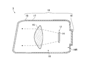
- FIG. 2 is a side view schematically showing one lamp part 5 shown in FIG.
- the lamp unit 5 includes a lamp unit 10 and a housing 16 as main components.
- the housing 16 is shown in a vertical section.
- the housing 16 has a lamp housing 17, a front cover 18, and a back cover 19 as main components.
- the front of the lamp housing 17 is open, and a front cover 18 is fixed to the lamp housing 17 so as to close the opening.
- An opening smaller than the front is formed in the rear of the lamp housing 17, and a back cover 19 is fixed to the lamp housing 17 so as to cover the opening.
- a space formed by the lamp housing 17, the front cover 18, and the back cover 19 is a lamp chamber 10R, and the lamp unit 10 is accommodated in the lamp chamber 10R.
- the lamp unit 10 includes a light distribution pattern forming section 12 and a projection lens 15 as main components.
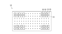
- FIG. 3 is a front view schematically showing the light distribution pattern forming section 12 shown in FIG.
- the light distribution pattern forming section 12 of this embodiment includes a plurality of light emitting elements 13 as light emitting sections for emitting light, and a circuit board 14 on which the plurality of light emitting elements 13 are mounted. and The plurality of light emitting elements 13 are arranged in a matrix to form rows in the vertical and horizontal directions, and emit light forward. These light-emitting elements 13 can individually change the amount of emitted light.
- the light distribution pattern forming section 12 has 64 light emitting element groups each made up of 256 light emitting elements 13 aligned in the horizontal direction, and these light emitting element groups are aligned in the vertical direction. Further, these light emitting elements 13 are micro LEDs, and the light distribution pattern forming section 12 is a so-called micro LED array.
- the number of light emitting elements 13 in each light emitting element group and the number of light emitting element groups are not particularly limited.
- Such a light distribution pattern forming unit 12 can form a predetermined light distribution pattern by selecting the light emitting elements 13 that emit light. Further, the light distribution pattern forming unit 12 can adjust the intensity distribution of light in a predetermined light distribution pattern by adjusting the amount of light emitted from each light emitting element 13 . Therefore, the light distribution pattern forming unit 12 can form a predetermined light distribution pattern according to the amount of light emitted from the plurality of light emitting elements 13 .
- the projection lens 15 is a lens that adjusts the divergence angle of incident light.
- the projection lens 15 is arranged in front of the light distribution pattern forming section 12 , the light emitted from the light distribution pattern forming section 12 is incident thereon, and the projection lens 15 adjusts the divergence angle of this light.
- the projection lens 15 of the present embodiment is a lens having a convex entrance surface and a convex exit surface. located on or near the surface. The light whose divergence angle has been adjusted by the projection lens 15 is emitted from the lighting unit 5 toward the front of the vehicle 100 through the front cover 18 .
- FIG. 4 is a diagram for explaining irradiation spots irradiated with light from the respective light emitting elements 13 shown in FIG.
- An irradiation spot 20 shown in FIG. 4 is an area irradiated with light from the light emitting element 13 on a virtual vertical screen placed 25 m ahead of the vehicle 100 .
- S indicates a horizontal line
- V indicates a vertical line passing through the center of the vehicle 100 in the left-right direction. Since the plurality of light emitting elements 13 in the light distribution pattern forming portion 12 are arranged in a matrix as described above, the irradiation spots 20 in front of the vehicle 100 irradiated with light from the respective light emitting elements 13 are , arranged in a matrix.
- the lamp unit 10 emits the light from the plurality of light emitting elements 13 so that the irradiation spots 20 irradiated with the light from the respective light emitting elements 13 are arranged in a matrix.
- the number of the plurality of irradiation spots 20 is reduced in FIG. 4 for easy understanding.
- Each irradiation spot 20 corresponds to one light emitting element 13 .
- the relative position of a specific light emitting element 13 among the plurality of light emitting elements 13 and the relative position of a specific irradiation spot 20 corresponding to this specific light emitting element 13 among the plurality of irradiation spots 20 are inverted vertically and horizontally. ing.
- the irradiation spot 20 corresponding to the light-emitting element 13 positioned at the upper right end from the viewpoint of the driver of the vehicle 100 is positioned at the lower left end from the viewpoint of the driver of the vehicle 100 .
- these irradiation spots 20 are square-shaped with approximately the same size, and adjacent irradiation spots 20 are in contact with each other.
- a region 30 formed from the entire irradiation spot 20 has a rectangular shape elongated in the left-right direction. This area 30 is an area where the lamp unit 10 can irradiate light.
- the vertical center of the area 30 is located on or near the horizontal line S, and the horizontal center of the area 30 is located on or near the vertical line V. located nearby.
- Adjacent irradiation spots 20 may overlap each other, or may be spaced apart from each other. However, it is preferable that the plurality of irradiation spots 20 be arranged in a matrix without gaps.
- the shape of the irradiation spot 20 is not particularly limited, and may be rectangular, for example.
- the plurality of irradiation spots 20 may include irradiation spots 20 having different sizes and shapes.
- control unit CO shown in FIG. can be used. Further, when the NC device is used, the controller CO may use a machine learning device or may not use a machine learning device. As will be described later, the controller CO controls the lamp unit 10 .
- the light switch 110 of this embodiment is a switch that selects light emission or non-emission, and is connected to the control unit CO.
- the light switch 110 outputs a signal indicating light emission to the control unit CO when it is on, and does not output a signal to the control unit CO when it is off.
- the other vehicle detection unit 120 of this embodiment includes a camera, a detection unit, etc. (not shown).
- the camera is attached to the front part of the vehicle 100 and photographs the front of the vehicle 100 at predetermined time intervals, for example, 50 msec intervals.
- a captured image captured by the camera includes at least part of the area 30 that can be irradiated with the light emitted from the pair of lamp units 5 .
- the detection unit detects the presence of other vehicles from the captured image captured by the camera and the position of the other vehicle in the captured image.
- the detection unit When detecting another vehicle positioned in front of the vehicle 100, the detection unit detects a signal indicating other vehicle information such as the existence of the other vehicle, the photographed image of the other vehicle, and the position of the other vehicle in the photographed image. Output to the determination unit 50 .
- the detector calculates the distance from the vehicle 100 to the other vehicle based on the captured image captured by the camera. For example, when the other vehicle is an oncoming vehicle, a pair of whitish light spots due to the light emitted from the headlights of the oncoming vehicle appear in the photographed image.
- the detection unit calculates the distance from the vehicle 100 to the oncoming vehicle based on the distance between the pair of white light spots and outputs a signal indicating the calculated distance to the boundary determination unit 50 .
- the detection unit calculates the distance from the vehicle 100 to the preceding vehicle based on the distance between the pair of red light spots, and outputs a signal indicating the calculated distance to the boundary determination unit 50 .
- the detection unit does not detect another vehicle located in front of the vehicle 100, it outputs a signal to the boundary determination unit 50 indicating that the other vehicle is not detected.
- the camera photographs the front of the vehicle 100 at predetermined time intervals. Therefore, a signal indicating the other vehicle information or a signal indicating that the other vehicle is not detected is output from the detection unit to the boundary determination unit 50 at approximately predetermined time intervals. Note that the detection unit does not have to output a signal to the boundary determination unit 50 when it does not detect another vehicle.
- the configuration of the detection unit may be, for example, the same configuration as the control unit CO, and the camera may be, for example, a CCD (Charged Coupled Device) camera.
- CCD Charge Coupled Device
- the configuration of the other vehicle detection unit 120, the method of detecting another vehicle by the other vehicle detection unit 120, the method of calculating the distance from the vehicle 100 to the other vehicle, and the other vehicle output from the other vehicle detection unit 120 to the boundary determination unit 50 Information is not particularly limited.
- the other vehicle detection unit 120 further includes an image processing unit that performs image processing on the captured image captured by the camera. The existing position of another vehicle may be detected.
- the other vehicle detection unit 120 may further include a millimeter wave radar, lidar, or the like that can detect an object located in front of the vehicle 100 .
- the other vehicle detection unit 120 detects the presence of another vehicle located in front of the vehicle 100 and detects the presence of the other vehicle relative to the vehicle 100 based on the captured image obtained by the camera and the information obtained by the millimeter wave radar, lidar, or the like. position and the distance from the vehicle 100 to the other vehicle may be detected.
- the steering sensor 130 is a running state detection unit that detects the running state of the vehicle 100 and is a sensor that detects the steering angle of the vehicle 100 .
- the steering sensor 130 detects the steering angle from the rotation angle of the steering wheel of the vehicle 100, for example.
- the steering sensor 130 detects the steering angles while distinguishing between the right steering angle and the left steering angle as different steering angles, and sends a signal indicating the detected steering angle, which is host vehicle information, to the boundary determination unit 50. Output.
- the tilt sensor 140 is a running state detection unit that detects the running state of the vehicle 100, and is a sensor that detects the tilt angle of the vehicle 100 in the pitch direction.
- the tilt sensor 140 is, for example, a gyro sensor.
- the tilt sensor 140 outputs a signal indicating the detected tilt angle, which is host vehicle information, to the boundary determination unit 50 .
- the vehicle speed sensor 150 is a running state detection unit that detects the running state of the vehicle 100 and is a sensor that detects the running speed of the vehicle 100 .
- the tilt sensor 140 detects the traveling speed from, for example, the number of revolutions of the tires.
- the vehicle speed sensor 150 outputs a signal indicating the detected running speed, which is host vehicle information, to the boundary determination unit 50 .
- the boundary determination unit 50 determines the position of the boundary between the bright area that should be brighter and the dark area that should be darker than the bright area in the area 30 where the lighting unit 10 can irradiate light, and outputs a signal indicating the position of the boundary. Output to control unit CO.
- the boundary determination unit 50 of the present embodiment includes a visual recognition unit for the driver of the other vehicle detected by the other vehicle detection unit 120 to visually recognize the outside of the vehicle, based on the other vehicle information from the other vehicle detection unit 120, and the above-described Determine the position of the boundary so that it overlaps with the dark area. Therefore, this boundary is not predetermined.
- the boundary determination unit 50 may determine the boundary position by selecting from a plurality of predetermined boundary positions based on the other vehicle information from the other vehicle detection unit 120 . If the other vehicle is an oncoming vehicle, for example, the front window or the like can be cited as the visual recognition portion for the driver of the other vehicle to visually recognize the outside of the vehicle. An imaging device for imaging the window, the rear of the vehicle, and the like can be cited. Preferably, the dark area defined by the boundary overlaps the entire viewing portion. In the present embodiment, the boundary determination unit 50 determines that a rectangular area that overlaps with the entire other vehicle should be darkened in the area 30 on the virtual vertical screen that is placed 25 m ahead of the vehicle 100, and the other areas should be darkened.
- the boundary has a rectangular shape surrounding the entire other vehicle. A predetermined gap is formed between this boundary and the outer edge of the other vehicle.
- the boundary determination unit 50 determines the position of such a boundary, outputs a signal indicating the boundary to the control unit CO, and stores information on the position of the boundary in a memory ME described later. For this reason, the memory ME stores information on changes over time in the position of the boundary. Note that the boundary determination unit 50 does not determine the position of the boundary when the distance from the vehicle 100 to another vehicle is greater than or equal to a predetermined distance, for example, 200 m or greater.
- the boundary determination unit 50 may determine the boundary position regardless of the distance from the vehicle 100 to the other vehicle 90 .
- the shape of the boundary is not particularly limited.
- a configuration of the boundary determination unit 50 for example, a configuration similar to that of the control unit CO can be cited. Note that the control unit CO may also serve as the boundary determination unit 50 .
- One power supply circuit 60 corresponds to one lamp unit 5
- the other power supply circuit 60 corresponds to the other lamp unit 5
- Each power supply circuit 60 includes a driver, and when a signal is input from the control section CO, the power supplied to each light emitting element 13 of the lamp unit 10 is adjusted by this driver. In this way, the amount of light emitted from each light emitting element 13 is adjusted.
- the driver of the power supply circuit 60 adjusts the power supplied to each light emitting element 13 by PWM (Pulse Width Modulation) control, thereby adjusting the amount of light emitted from each light emitting element 13. .
- PWM Pulse Width Modulation
- the method of adjusting the amount of light emitted from each light emitting element 13 is not particularly limited.
- the memory ME stores information and is configured so that the stored information can be read.
- the memory ME is, for example, a non-transitory recording medium, and is preferably a semiconductor recording medium such as a RAM (Random Access Memory) or a ROM (Read Only Memory). Any form of recording medium, such as a recording medium, may be included.
- non-transitory recording media include all computer-readable recording media excluding transitory, propagating signals, and do not exclude volatile recording media. Absent.
- the memory ME of the present embodiment stores information regarding power supplied to each light emitting element 13 when emitting a high beam.
- FIG. 5 is a diagram showing an example of a control flowchart of the control unit CO in this embodiment. As shown in FIG. 5, the control flow of this embodiment includes steps SP11 to SP15.
- Step SP11 the controller CO determines whether or not a signal is input from the light switch 110 .
- the control unit CO advances the control flow to step SP12.
- the control unit CO advances the control flow to step SP15. Therefore, it can be understood that the judgment of the control unit CO means that the next step is changed by classifying cases according to the input signal.
- Step SP12 the control unit CO determines whether or not the boundary position has been determined by the boundary determination unit 50 based on the signal input from the boundary determination unit 50 . If this signal is not input to the control unit CO, the control unit CO advances the control flow to step SP13. On the other hand, when this signal is input to the control unit CO, the control unit CO advances the control flow to step SP14.
- Step SP13 the controller CO controls the lamp unit 10 so that the vehicle headlamp 1 emits a high beam.
- the control unit CO refers to the information stored in the memory ME, and outputs to the power supply circuit 60 a control signal based on the power supplied to each light emitting element 13 when emitting the high beam. Based on this signal, the power supply circuit 60 supplies power to each light emitting element 13 from a power supply (not shown). Therefore, a high beam is emitted from the vehicle headlamp 1 . Then, the control unit CO returns the control flow to step SP11.
- FIG. 6 is a diagram showing a high beam light distribution pattern in this embodiment.
- S indicates a horizontal line
- V indicates a vertical line passing through the center of the vehicle 100 in the left-right direction
- a high beam light distribution pattern PH formed on a virtual vertical screen arranged 25 m ahead of the vehicle 100 is shown in FIG. indicated by a bold line.
- the outline of the light distribution pattern of the high beam matches the outline of the area 30 .
- the hot zone which is the region where the light intensity is the highest in the light distribution pattern PH of the high beam, is located on or near the intersection of the horizontal line S and the vertical line V. As shown in FIG.
- the intensity of light in the high-beam light distribution pattern PH decreases with increasing distance from the hot zone. Therefore, the light emitting element 13 is controlled so that the intensity distribution of light becomes like this.
- Step SP14 the control unit CO controls the lighting unit 10 so that the light distribution pattern of the light emitted from the vehicle headlamp 1 corresponds to the position of the boundary determined by the boundary determining unit 50. Control. Then, the control unit CO returns the control flow to step SP11.
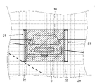
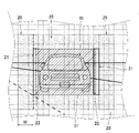
- FIG. 7 is a diagram showing an example of the position of the boundary determined by the boundary determination unit 50, and an example of the position of the boundary determined when the other vehicle 90, which is an oncoming vehicle, is detected by the other vehicle detection unit 120. It is a figure which shows.
- FIG. 8 is an enlarged view of the boundary 51 and its vicinity in FIG.
- S indicates a horizontal line
- V indicates a vertical line passing through the center of the vehicle 100 in the left-right direction
- a boundary 51 on a virtual vertical screen arranged 25 m ahead of the vehicle 100 is indicated by a thick line
- the irradiation spot 20 is shown in dashed lines. Note that the number of irradiation spots 20 is reduced in FIGS. 7 and 8 for easy understanding.
- the boundary 51 has a rectangular shape that surrounds the entire other vehicle 90 that is the oncoming vehicle. It is an exponential bright region. For this reason, the dark area to be darkened overlaps with the front window as a visual recognition portion for the driver of the other vehicle 90, which is an oncoming vehicle, to visually recognize the outside of the vehicle.
- the control unit CO determines whether the illuminance of the light from the lighting unit 10 in the irradiation spot 20 overlapping only the dark area to be darkened is the bright area to be brightened.
- the lighting unit 10 is controlled so that the illuminance of the light from the lighting unit 10 in the irradiation spot 20 overlapping the chisel is lower than that.
- the control unit CO controls the light-emitting element 13 so that the amount of light emitted from the light-emitting element 13 that irradiates the irradiation spot 20 overlapping only the dark region becomes zero.
- the control unit CO controls the light emitting element 13 so that the amount of light emitted from the light emitting element 13 that irradiates light onto the irradiation spot 20 overlapping only the bright area becomes the amount of light when the high beam is emitted.
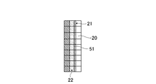
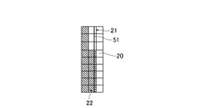
- the control unit CO determines that the total amount of light from the lamp unit 10 that irradiates the irradiation spot row 21 is , the lamp unit 10 is controlled so as to decrease according to the ratio of the portion 22 overlapping the dark region in the irradiation spot row 21 .
- the irradiation spot array 21 is indicated by thick lines, and the dark areas to be darkened are hatched with oblique lines.
- the control unit CO reduces the illuminance of the light applied to each irradiation spot 20 of the irradiation spot row 21 stepwise according to the ratio of the portion 22 overlapping the dark region in the irradiation spot 20.
- the lamp unit 10 is controlled as follows.
- the illuminance of the light irradiated to each irradiation spot 20 of the irradiation spot row 21 is less than or equal to the illuminance of the light irradiated to the irradiation spot 20 adjacent to the bright region side of the irradiation spot 20. It is greater than or equal to the illuminance of the light irradiated to the irradiation spot 20 adjacent to the dark region side.
- FIG. 9 is a diagram showing an example of a state in which the illuminance of the light applied to the irradiation spot 20 is lowered step by step.
- FIG. 10 is a diagram showing another example of a state in which the illuminance of the light with which the irradiation spot 20 is irradiated is lowered stepwise.
- the unhatched irradiation spot 20 is the irradiation spot 20 that overlaps only the bright region, and the irradiation spot corresponding to the light emitting element 13 whose emitted light quantity is the light quantity when the high beam is emitted. is 20.
- the irradiation spots 20 hatched with oblique lines are the irradiation spots 20 that overlap only with the dark regions, and are the irradiation spots 20 that correspond to the light emitting elements 13 that emit zero light.
- a hatched irradiation spot 20 consisting of a plurality of dots is the irradiation spot 20 that constitutes the irradiation spot row 21, and the plurality of hatched dots in FIG. 10 are finer than in FIG. The finer the hatched dots, the lower the illuminance of the light irradiated to the irradiation spot 20 .
- the control unit CO of the present embodiment controls each irradiation spot 20 in the irradiation spot row 21 as shown in FIG.
- the light emitting element 13 is controlled so that the amount of light emitted from the light emitting element 13 for irradiating is a predetermined amount smaller than the light amount when the high beam is emitted.
- the amounts of light emitted from these light emitting elements 13 are assumed to be the same, they may be different.
- the control unit CO controls the amount of light emitted from the light emitting element 13 that irradiates each irradiation spot 20 of the irradiation spot row 21 with light, as shown in FIG. is less than the amount of light in the state shown in FIG. Therefore, in the present embodiment, the illuminance of the light irradiated to each irradiation spot 20 of the irradiation spot row 21 is lowered in two stages according to the above ratio.
- FIG. 11 is a diagram showing an example of a light distribution pattern corresponding to the boundary 51 shown in FIG.
- S indicates a horizontal line
- V indicates a vertical line passing through the center of the vehicle 100 in the left-right direction
- the light distribution pattern 200 on the virtual vertical screen arranged 25 m ahead of the vehicle 100 is indicated by a thick line.
- Step SP15 In this step, no signal is input from the light switch 110 to the controller CO. Therefore, the light switch 110 is off.
- the control unit CO controls the lighting unit 10 so that the light from the lighting unit 10 is not emitted, and the light from the vehicle headlamp 1 is not emitted. Then, the control flow is returned to step SP11.
- the light distribution pattern PH of the emitted high beam has the darkened area 210 when the position of the boundary 51 is determined by the boundary determination unit 50. Transformed into a light pattern 200 . This darkened area 210 also changes as the position of the boundary 51 changes.
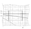
- FIG. 12 is a diagram showing an example of how the boundary changes, and is a diagram showing an example of how the boundary changes so as to move in the horizontal direction.
- the boundary determination unit 50 of the present embodiment determines the position of the boundary 51c based on the other vehicle information input from the other vehicle detection unit 120 at a first timing and the position of the boundary 51c at the first timing.
- the position of the boundary 51a is different, the position of the boundary is changed stepwise. This change in the position of the boundary is performed during the period from the first timing to the second timing when the other vehicle information is input from the other vehicle detection unit 120 immediately after the first timing.
- the boundary determination unit 50 of the present embodiment determines the boundary between the first timing and the second timing based on the information on the position of the boundary 51a at the first timing and the other vehicle information input at the first timing. position is changed step by step.
- the boundary changes from boundary 51a to boundary 51b and then to boundary 51c, but the number of stages of change is not particularly limited.
- the method of stepwise change of the boundary is not particularly limited. For example, when the boundary changes so as to move, the position of the boundary may be changed in steps so that the boundary moves at a substantially constant speed. Moreover, when the boundary changes so as to be deformed, the position of the boundary may be changed stepwise so that the shape of the boundary approaches the shape of the boundary after deformation at a substantially constant rate.
- control flow of the control unit CO is not particularly limited. Moreover, in the present embodiment, the steering sensor 130 , the tilt sensor 140 , and the vehicle speed sensor 150 may not output signals to the boundary determining section 50 .
- the vehicle headlamp 1 of this embodiment includes the lamp unit 10, the boundary determination section 50, and the control section CO.
- the lamp unit 10 has a plurality of light emitting elements 13 that can individually change the amount of emitted light. Light from the element 13 is emitted.
- the boundary determining section 50 determines the position of a boundary 51 between a bright area to be brightened and a dark area to be darker than the bright area in the area 30 to which the lighting unit 10 can emit light.
- the controller CO controls the lighting unit 10 based on the position of the boundary 51 . Therefore, in the vehicle headlamp 1 of the present embodiment, the light distribution pattern of the emitted light changes as the boundary 51 changes.
- the control unit CO adjusts the illuminance of the light irradiated to each irradiation spot 20 of the irradiation spot row 21 to the bright region side of the irradiation spot 20.
- the lighting unit 10 is controlled so that the illuminance of the light irradiated to the adjacent irradiation spot 20 is less than or equal to the illuminance of the light irradiated to the irradiation spot 20 adjacent to the dark region side of the irradiation spot 20 .
- control unit CO controls the lighting unit 10 so that the total amount of light from the lighting unit 10 that irradiates the irradiation spot row 21 decreases according to the ratio of the portion 22 overlapping the dark region in the irradiation spot row 21.
- One side of the irradiation spot row 21 is a region to be brightened, and the other side is a region to be darkened.
- the illuminance of the light irradiated to each irradiation spot 20 of the irradiation spot row 21 is equal to or less than the illuminance of the adjacent brightened area and equal to or more than the illuminance of the adjacent darkened area.
- the total amount of light from the lamp unit 10 that irradiates the irradiation spot row 21 decreases according to the ratio of the portion 22 overlapping the dark region to be darkened in the irradiation spot row 21 .
- the position of the boundary 51 changes so as to increase the ratio
- the region where the irradiation spot row 21 is gradually darkened according to the increase in the ratio. become.
- the position of the boundary 51 changes so as to decrease this ratio
- the illuminated spot array becomes a region in which the brightness is gradually increased according to the decrease in ratio.
- the vehicle headlamp 1 of the present embodiment changes the entire illuminated spot array 21 from a brightened area to a darkened area at a certain timing, or from a darkened area to a brightened area.
- the change in the light distribution pattern of emitted light can be made smoother than when it changes. Therefore, according to the vehicle headlamp 1 of the present embodiment, it is possible to reduce the feeling of strangeness in the light distribution pattern of the emitted light compared to this case.
- the boundary determination unit 50 detects the outside of the vehicle by the driver of the other vehicle 90 based on the other vehicle information from the other vehicle detection unit 120 that detects the other vehicle 90 .
- the position of the boundary 51 is determined so that the visual recognition part and the dark area for the image overlap. According to the vehicle headlamp 1 of the present embodiment, the visible part and the darkened area can be overlapped, and the glare given to the driver of the other vehicle 90 can be suppressed.
- the boundary determination unit 50 inputs the boundary position information at the first timing when the other vehicle information from the other vehicle detection unit 120 is input, and the boundary position information is input at the first timing. Based on the other vehicle information, the position of the boundary 51 is changed step by step during the period from the first timing to the second timing when the other vehicle information is input from the other vehicle detection unit 120 immediately after the first timing. Therefore, according to the vehicle headlamp 1 of the present embodiment, the change in the light distribution pattern of the emitted light can be made smoother, and the change in the light distribution pattern can further reduce discomfort.
- the boundary determination unit 50 may change the boundary 51 as follows.
- the memory ME stores information on changes over time in the position of the boundary 51 .
- the boundary determination unit 50 obtains information on changes over time in the position of the boundary 51 during a predetermined period before the first timing including the first timing at which the other vehicle information is input from the other vehicle detection unit 120 and the first timing. Based on the other vehicle information from the other vehicle detection unit 120 input to the boundary during the period from the first timing to the second timing at which the other vehicle information is input from the other vehicle detection unit 120 immediately after the first timing
- the position of 51 may be changed stepwise.
- the boundary determination unit 50 determines the boundary at the second timing based on the information on the temporal change in the position of the boundary 51 and the other vehicle information from the other vehicle detection unit 120 input at the first timing.
- the position of the boundary may be predicted, and the position of the boundary may be changed stepwise during the period from the first timing to the second timing based on the temporal change of the position of the boundary 51 and information on the predicted position of the boundary. .
- the controller CO controls the illuminance of the light irradiated to each irradiation spot 20 of the irradiation spot row 21 so that the illuminance of the portion 22 overlapping the dark region in the irradiation spot 20 is
- the lamp unit 10 is controlled so as to be lowered stepwise according to the ratio. Therefore, according to the vehicle headlamp 1 of the present embodiment, the change in the light distribution pattern of the emitted light can be made smoother, and the change in the light distribution pattern can further reduce discomfort. Further, according to the vehicle headlamp 1 of the present embodiment, the calculation load of the control unit CO can be reduced compared to the case where the illuminance of the light is continuously lowered according to the above ratio.
- the number of steps in which the illuminance is lowered according to the above ratio is not particularly limited, it is preferably 16 or less from the viewpoint of reducing the calculation load of the control unit CO. Further, the number of stages may be different between the case where the position of the boundary 51 changes so as to increase the above rate and the case where the position of the boundary 51 changes so as to decrease the above rate. For example, when the position of the boundary 51 changes such that the proportion increases, the number of steps may be less than when the position of the boundary 51 changes such that the proportion decreases.
- the case where the position of the boundary 51 changes so as to increase the above ratio is a state in which the position of the boundary 51 changes so that the irradiation spot row 21 becomes a darkened region.
- the case where the position of the boundary 51 changes so as to decrease the above ratio is a state in which the position of the boundary 51 changes so that the irradiation spot array 21 becomes a brighter region. Therefore, with such a configuration, for example, in a state where the speed of change in the position of the boundary 51 is constant, the time required for the irradiation spot array 21 to become a darkened area is It can be shorter if it becomes an area to be brightened. Therefore, compared to the case where the number of steps is constant regardless of how the position of the boundary 51 changes, an increase in the calculation load of the control unit CO is suppressed, and glare given to the driver of the other vehicle 90 is suppressed. can.
- FIG. 13 is a diagram for explaining the control of the lamp unit 10 in this embodiment, and is a diagram showing the vicinity of the boundary 51 and the irradiation spot 20 in the vicinity of the boundary 51 in the same manner as FIG.
- the controller CO of the present embodiment controls the lighting unit 10 so as to form a blurred area that overlaps the bright area and is adjacent to the boundary 51, and that the illuminance of the emitted light gradually decreases as it approaches the boundary 51. do.
- the light-emitting element 13 for irradiating the irradiation spot group 25 is controlled so that the irradiation spot group 25 formed by the irradiation spot 20 hatched with a plurality of dots becomes a blurred area. do.
- the irradiation spots 20 of this irradiation spot group 25 are a plurality of rows of irradiation spots 20 that overlap only the bright region and are arranged along the boundary 51 .
- the illuminance of the light applied to the irradiation spot 20 of the irradiation spot group 25 is lower than the illuminance of the light applied to the irradiation spot 20 when the high beam is emitted. Further, among the plurality of irradiation spots 20 arranged in a direction perpendicular to the boundary 51, the illuminance of the light irradiated to the irradiation spots 20 located on the boundary 51 side is applied to the irradiation spots 20 located on the opposite side to the boundary 51 side.
- control unit CO controls the amount of light emitted from the light emitting element 13 that irradiates the irradiation spot 20 overlapping only the bright area other than the irradiation spot 20 in the irradiation spot group 25 so that the amount of light emitted from the light emitting element 13 becomes the amount of light when the high beam is emitted. , the light emitting element 13 is controlled. Further, similarly to the first embodiment, the control unit CO controls the light emitting element 13 so that the amount of light emitted from the light emitting element 13 that irradiates light onto the irradiation spot 20 that overlaps only the dark region becomes zero. .
- a light distribution pattern 300 is formed in which the intensity of light in a region 320 overlapping with the group 25 is reduced stepwise as it approaches the region 310 .
- the region 310 overlaps the front windshield as the visible portion of the other vehicle 90 .
- Region 320 is the blurred region described above and extends along the outer edge of region 310 .
- FIG. 14 is a diagram showing an example of the light distribution pattern in this embodiment, similar to FIG. 11, and is an example of the light distribution pattern corresponding to the boundary 51 shown in FIG.
- the vehicle headlamp 1 of the present embodiment it is possible to reduce the sense of discomfort caused by changes in the light distribution pattern, compared to the case where the blurred area is not formed.
- the control unit CO of the present embodiment controls the lighting unit 10 to irradiate a portion 26 on the bright region side of the irradiation spot row 21 in the blurred region.
- the lamp unit 10 is controlled so that the total amount of light of 1 is reduced according to the ratio of the portion 22 overlapping the dark region in the irradiation spot array 21 .
- a portion 26 on the bright region side of the irradiation spot row 21 in the blurred region is surrounded by a dashed-dotted line.
- the total amount of light from the lamp unit 10 that irradiates the irradiation spot row 21 decreases.
- the total amount of light from the lamp unit 10 that irradiates the portion 26 decreases. Therefore, the difference between the brightness of the irradiation spot array 21 and the brightness of the portion 26 can be reduced, and it is possible to reduce the sense of incongruity in the change of the light distribution pattern.
- the width W of the blurring area in the direction perpendicular to the boundary 51 is not particularly limited, and the width W may not be constant. It may vary according to the ratio of 22.
- the boundary determination unit 50 of the present embodiment determines whether the lighting unit 10 emits light based on the own vehicle information from the steering sensor 130, the tilt sensor 140, and the vehicle speed sensor 150, which are the running state detection units that detect the running state of the own vehicle.
- the position of the boundary 51 is determined so that a predetermined area from the outer edge of the area 30 capable of irradiating is a dark area.
- FIG. 15 is a diagram showing an example of the position of the boundary determined by the boundary determination unit 50 of this embodiment.
- FIG. 8 is a view similar to FIG. 7 showing an example of positions;
- the boundary 51 in this embodiment corresponds to the outer shape of the light distribution pattern emitted from the vehicle headlamp 1, and corresponds to the outer shape of the light distribution pattern of the high beam in a rectangular shape elongated in the left-right direction. , spaced apart from the outer edge of region 30 .
- the area from the outer edge of the area 30 to the boundary 51 is a dark area that should be darkened, and the inside of the boundary 51 is a bright area that should be brightened.
- the boundary determination unit 50 moves the position of the entire boundary 51 in the horizontal direction by a predetermined distance according to the steering angle. This predetermined distance according to the steering angle is a distance based on the position of the boundary 51 shown in FIG. In the case of the steering angle to , it is the distance to the right.
- the predetermined distance corresponding to the steering angle is short when the steering angle is small and long when the steering angle is large, and in the present embodiment, it becomes longer in stages as the steering angle increases.
- the boundary determination unit 50 moves the position of the entire boundary 51 in the vertical direction by a predetermined distance according to the tilt angle.
- the predetermined distance corresponding to the tilt angle is a distance based on the position of the boundary 51 shown in FIG. 15, and is a downward distance when the tilt angle is upward. In the case of inclination angle to , it is the distance upward.
- the predetermined distance corresponding to the tilt angle is short when the tilt angle is small and long when the tilt angle is large, and in the present embodiment, the distance increases stepwise as the tilt angle increases.
- the boundary determination unit 50 changes the position of the boundary 51 so that the width of the boundary 51 in the horizontal direction becomes about 4/5.
- the control unit CO of the present embodiment controls the light emitting element 13 so that the amount of light emitted from the light emitting element 13 that irradiates the irradiation spot 20 overlapping only the dark area becomes zero.
- the control unit CO controls the irradiation spots 20 overlapping only the bright regions so that the illuminance of the light in the regions composed of the irradiation spots 20 overlapping only the bright regions decreases as the distance from the center of the regions increases outward.
- the light emitting element 13 that emits light is controlled. Therefore, the outer shape of the light distribution pattern of the light emitted from the vehicle headlamp 1 of the present embodiment is substantially the same as that of the boundary 51 .
- the vehicle headlamp of the present embodiment when the running speed of the vehicle 100 exceeds a predetermined speed, the light distribution pattern is changed so that the width of the emitted light in the left-right direction becomes smaller.
- the shape can be changed. Therefore, according to the vehicle headlamp of the present embodiment, the line of sight of the driver during high-speed driving can be easily concentrated in the vicinity of the central portion in front of the vehicle, and distant visibility can be improved. Further, according to the vehicle headlamp of the present embodiment, the direction in which the predetermined light distribution pattern is emitted can be changed according to the steering angle and the tilt angle of the vehicle 100 .
- the vehicle headlamp of the present embodiment light can be emitted to the traveling destination on a curved road, and light can be emitted in an appropriate direction even if the vehicle 100 is tilted in the pitch direction. Therefore, according to the vehicle headlamp 1 of the present embodiment, visibility in the traveling direction can be improved as compared with the case where the light emission direction does not change according to the steering angle and the tilt angle of the vehicle 100 .
- the illuminance of the light irradiated to each irradiation spot 20 of the irradiation spot row 21 is reduced stepwise according to the ratio of the portion 22 overlapping the dark region in the irradiation spot 20.
- the control unit CO that controls the unit 10 has been described as an example. However, the controller CO controls the lighting unit 10 so that the total amount of light from the lighting unit 10 that irradiates the irradiation spot row 21 decreases according to the ratio of the portion 22 overlapping the dark region in the irradiation spot row 21. You can control it.
- control unit CO controls the lamp so that the illuminance of the light irradiated to each irradiation spot 20 of the irradiation spot row 21 is continuously lowered according to the ratio of the portion 22 overlapping the dark region in the irradiation spot 20.
- Unit 10 may be controlled.
- control unit CO reduces the illuminance of the light irradiated to at least one irradiation spot 20 in the irradiation spot row 21 stepwise according to the ratio of the portion 22 overlapping the dark region in the irradiation spot 20.
- the lighting unit 10 may be controlled.
- control unit CO may control the lamp unit 10 as in a modified example described below.
- FIG. 16 is a diagram showing an example of a state in which the illuminance of the light irradiated to the irradiation spot 20 changes in the modified example
- FIG. 17 shows a state in which the illuminance of the light irradiated to the irradiated spot 20 changes in the modified example. It is a figure which shows another example of.
- the unhatched irradiation spot 20 is the irradiation spot 20 corresponding to the light-emitting element 13 whose emitted light quantity is the light quantity when the high beam is emitted.
- the irradiation spots 20 hatched with oblique lines are the irradiation spots 20 corresponding to the light emitting elements 13 that emit zero light.
- the ratio of the portions 22 overlapping the dark regions in the irradiation spot array 21 in FIG. 16 is 25%, and the ratio of the portions 22 overlapping the dark regions in the irradiation spot array 21 in FIG. 17 is 75%.
- the illuminance of the light irradiated to a part of the irradiation spot 20 in the irradiation spot row 21 becomes the illuminance of the light irradiated to the irradiation spot 20 adjacent to the dark region side of the irradiation spot.
- the lamp unit 10 is controlled as follows.
- the control unit CO of the present modified example adjusts the illuminance of the irradiated light to the irradiation spot 20 adjacent to the dark region side of the irradiation spot 20 according to the ratio of the portion 22 overlapping the dark region in the irradiation spot row 21.
- the lamp unit is controlled so as to increase the number of irradiation spots 20 in the irradiation spot row 21, which is the illuminance of the irradiated light. Specifically, when the ratio of the portion 22 overlapping the dark region in the irradiation spot row 21 is less than 50%, as shown in FIG.
- the light emitting element 13 is controlled so that the amount of light emitted from the light emitting element 13 becomes zero.
- the control unit CO controls the amount of light emitted from the light emitting elements 13 that irradiate the irradiation spots 20 of the irradiation spot row 21 with light, as shown in FIG.
- the light-emitting elements 13 are controlled so that the number of the light-emitting elements 13 with zero is greater than when the above ratio is less than 50%.
- the illuminance of the light irradiated to the irradiation spot 20 adjacent to the dark region side is increased in order from the irradiation spot 20 located on the one end side of the irradiation spot row 21. Illuminance.
- the order of the irradiation spots 20 is not particularly limited so that the illuminance of the irradiated light becomes the illuminance of the light irradiated to the irradiation spot 20 adjacent to the dark region side.
- the illuminance of the irradiated light may be the illuminance of the light irradiated to the adjacent irradiation spot 20 on the dark region side in order from the irradiation spot 20 positioned on the center side of the irradiation spot row 21 .
- control unit CO reduces the illuminance of the light irradiated to some of the irradiation spots 20 in the irradiation spot row 21 in stages according to the ratio of the portion overlapping the dark region in the irradiation spot 20, and the irradiation In the irradiation spot row 21, the illuminance of the irradiated light becomes the illuminance of the light irradiated to the irradiation spot 20 adjacent to the dark region side of the irradiation spot 20 according to the ratio of the portion overlapping the dark region in the spot row 21
- the lamp unit 10 may be controlled so that the number of irradiation spots 20 increases.
- the amount of light emitted from the light emitting element 13 that irradiates light onto the irradiation spot 20 that overlaps only the dark region is set to zero.
- the illuminance of the light irradiated to the irradiation spot 20 overlapping only the dark region is lower than the illuminance of the light irradiated to the irradiation spot 20 overlapping only the bright region. Therefore, the amount of light emitted from the light emitting element 13 that irradiates the irradiation spot 20 that overlaps only the dark region may not be zero.
- the boundary determination unit 50 that determines the position of the boundary 51 based on the own vehicle information from the steering sensor 130, the tilt sensor 140, and the vehicle speed sensor 150, which are the driving state detection units, will be described as an example. bottom.
- the boundary determination unit 50 may determine the position of the boundary 51 based on the own vehicle information from the running state detection unit that detects the running state of the vehicle 100 .
- the boundary determination unit 50 may determine the boundary 51 based on host vehicle information from at least one of the steering sensor 130 , the tilt sensor 140 and the vehicle speed sensor 150 .
- the boundary determination unit 50 that determines the position of the boundary 51 corresponding to the outline of the light distribution pattern of the high beam has been described as an example.
- the boundary determination section 50 may determine the position of the boundary 51 so that a predetermined area from the outer edge of the area 30 to which the lamp unit 10 can irradiate light becomes a dark area.
- at least part of the outer shape of the light distribution pattern of emitted light is substantially the same as at least part of the boundary. Therefore, according to such a configuration, it is possible to change the outline of the light distribution pattern of emitted light or change the emission direction of light having a predetermined light distribution pattern according to the running state of the own vehicle. obtain.
- the boundary determination unit 50 may determine the position of the boundary 51 corresponding to the outer shape of the light distribution pattern of the low beam, for example. Also, the shape of the boundary 51 is not particularly limited, and the boundary 51 may be connected to the outer edge of the region 30 .
- the above embodiments can be combined as appropriate.
- the first embodiment and the third embodiment may be combined, and the boundary determination unit 50 in the first embodiment may determine the position of the boundary in the first embodiment and the position of the boundary in the second embodiment. good.
- the controller CO may control the lamp unit 10 so that the blurring area shown in the second embodiment is formed.
- the illuminance of the light irradiated to each irradiation spot 20 of the irradiation spot row 21 decreases stepwise according to the ratio of the portion 22 overlapping the dark region in the irradiation spot 20 is not particularly limited. As noted above, this number of steps may be different for cases where the position of the boundary 51 changes such that the proportion increases and where the position of the boundary 51 changes such that the proportion decreases. . For example, when the position of the boundary 51 changes such that the proportion increases, the number of steps may be less than when the position of the boundary 51 changes such that the proportion decreases.
- the lamp unit 10 including the light distribution pattern forming section 12 having the plurality of light emitting elements 13 capable of individually changing the amount of emitted light has been described as an example.
- the lamp unit 10 has a plurality of light emitting portions that can individually change the amount of emitted light. It is only necessary to emit the light from the light emitting portion.
- the lamp unit 10 may include a light distribution pattern forming section having a DMD (Digital Mirror Device) including a plurality of reflective elements arranged in a matrix and a light source section for irradiating the DMD with light.
- DMD Digital Mirror Device
- the DMD can adjust the amount of light emitted in a predetermined direction from the reflecting surface of each reflecting element, and irradiation spots irradiated with light emitted in a predetermined direction from each reflecting element are arranged in a matrix. Therefore, it can be understood that the reflecting surface of each reflecting element corresponds to the above-described light emitting portion.
- the lamp part 5 including one lamp unit 10 has been described as an example.
- the lamp part 5 further includes a lamp unit different from the lamp unit 10, and the vehicle headlamp 1 produces a predetermined light distribution pattern by the light emitted from the lamp unit 10 and the light emitted from the other lamp unit. may be formed.
- the configuration of the separate lamp unit is not particularly limited, and may have the same configuration as the lamp unit 10, for example.
- a vehicle headlamp capable of reducing discomfort caused by changes in the light distribution pattern of emitted light, and can be used in fields such as vehicle headlamps for automobiles and the like.
Landscapes
- Engineering & Computer Science (AREA)
- Mechanical Engineering (AREA)
- Physics & Mathematics (AREA)
- Mathematical Physics (AREA)
- Microelectronics & Electronic Packaging (AREA)
- Optics & Photonics (AREA)
- General Engineering & Computer Science (AREA)
- Lighting Device Outwards From Vehicle And Optical Signal (AREA)
Abstract
Description
図1は、本実施形態における車両用前照灯を備える車両を概念的に示す平面図である。図1に示すように、本実施形態の車両100は、自動車であり、車両用前照灯1と、ライトスイッチ110と、車両100の前方に位置する他車両を検出する他車両検出部120と、ステアリングセンサ130と、傾斜センサ140と、車速センサ150と、を備える。
本ステップでは、制御部COは、ライトスイッチ110から信号が入力するか否かを判断する。この信号が制御部COに入力される場合、制御部COは制御フローをステップSP12に進める。一方、この信号が制御部COに入力されない場合、制御部COは制御フローをステップSP15に進める。このため、制御部COの判断とは、このように入力する信号に応じて場合分けをして次に進むステップを変更することと理解できる。
本ステップは、制御部COは、境界決定部50から入力する信号に基づいて、境界決定部50によって境界の位置が決定されたか否かを判断する。この信号が制御部COに入力されない場合、制御部COは制御フローをステップSP13に進める。一方、この信号が制御部COに入力される場合、制御部COは制御フローをステップSP14に進める。
本ステップでは、制御部COは、車両用前照灯1からハイビームが出射するように、灯具ユニット10を制御する。具体的には、制御部COは、メモリMEに記憶される情報を参照し、ハイビームを出射する際にそれぞれの発光素子13に供給される電力に基づく制御信号を電源回路60に出力する。電源回路60は、この信号に基づいて、図示しない電源からそれぞれの発光素子13に電力を供給する。このため、車両用前照灯1からハイビームが出射する。そして、制御部COは、制御フローをステップSP11に戻す。
本ステップでは、制御部COは、車両用前照灯1から出射する光の配光パターンが境界決定部50によって決定される境界の位置に応じた配光パターンとなるように、灯具ユニット10を制御する。そして、制御部COは、制御フローをステップSP11に戻す。
本ステップでは、ライトスイッチ110から制御部COに信号は入力されていない。このため、ライトスイッチ110はオフである。制御部COは、灯具ユニット10からの光が非出射となるように、灯具ユニット10を制御し、車両用前照灯1からの光を非出射とする。そして、制御フローをステップSP11に戻す。
次に、本発明の第2実施形態について詳細に説明する。なお、第1実施形態と同一又は同等の構成要素については、特に説明する場合を除き、同一の参照符号を付して重複する説明は省略する。本実施形態では、境界51の位置が決定される際に出射する光の配光パターンが第1実施形態と異なる。
次に、本発明の第3実施形態について詳細に説明する。なお、第1実施形態と同一又は同等の構成要素については、特に説明する場合を除き、同一の参照符号を付して重複する説明は省略する。本実施形態では、境界決定部50によって決定される境界51の位置が第1実施形態と異なる。
Claims (13)
- 出射する光の光量を個別に変更可能な複数の光出射部を有し、それぞれの前記光出射部からの光が照射される照射スポットがマトリックス状に並ぶように複数の前記光出射部からの光を出射する灯具ユニットと、
前記灯具ユニットが光を照射可能な領域において明るくすべき明領域と前記明領域より暗くすべき暗領域との境界の位置を決定する境界決定部と、
前記灯具ユニットを制御する制御部と、
を備え、
前記制御部は、前記境界と重なる前記照射スポットから成る照射スポット列において、前記照射スポット列のそれぞれの前記照射スポットに照射される光の照度が、当該照射スポットの前記明領域側に隣接する前記照射スポットに照射される光の照度以下、当該照射スポットの前記暗領域側に隣接する前記照射スポットに照射される光の照度以上となるとともに、前記照射スポット列に照射される前記灯具ユニットからの光の総量が、当該照射スポット列における前記暗領域と重なる部位の割合に応じて少なくなるように前記灯具ユニットを制御する
ことを特徴とする車両用前照灯。 - 前記境界決定部は、他車両を検出する他車両検出部からの他車両情報に基づいて、前記他車両の運転者が車外を視認するための視認部と前記暗領域とが重なるように前記境界の位置を決定する
ことを特徴とする請求項1に記載の車両用前照灯。 - 前記境界決定部は、自車両の走行状態を検出する走行状態検出部からの自車両情報に基づいて、前記灯具ユニットが光を照射可能な前記領域の外縁から所定の領域が前記暗領域となるように前記境界の位置を決定し、
前記制御部は、前記暗領域のみと重なる前記照射スポットに対応する前記光出射部から出射する光の光量がゼロとなるように前記灯具ユニットを制御する
ことを特徴とする請求項1に記載の車両用前照灯。 - 前記境界決定部は、前記他車両情報が入力する第1タイミングにおける前記境界の位置の情報及び前記他車両情報に基づいて、前記第1タイミングから当該第1タイミングの直後に前記他車両情報が入力する第2タイミングまでの期間中における前記境界の位置を段階的に変化させる
ことを特徴とする請求項2に記載の車両用前照灯。 - 前記境界決定部は、前記自車両情報が入力する第1タイミングにおける前記境界の位置の情報及び前記自車両情報に基づいて、前記第1タイミングから当該第1タイミングの直後に前記自車両情報が入力する第2タイミングまでの期間中における前記境界の位置を段階的に変化させる
ことを特徴とする請求項3に記載の車両用前照灯。 - 前記境界決定部は、前記他車両情報が入力する第1タイミングを含む当該第1タイミング以前の所定期間における前記境界の位置の経時変化の情報及び前記他車両情報に基づいて、前記第1タイミングから当該第1タイミングの直後に前記他車両情報が入力する第2タイミングまでの期間中における前記境界の位置を段階的に変化させる
ことを特徴とする請求項2に記載の車両用前照灯。 - 前記境界決定部は、前記自車両情報が入力する第1タイミングを含む当該第1タイミング以前の所定期間における前記境界の位置の経時変化の情報及び前記自車両情報に基づいて、前記第1タイミングから当該第1タイミングの直後に前記自車両情報が入力する第2タイミングまでの期間中における前記境界の位置を段階的に変化させる
ことを特徴とする請求項3に記載の車両用前照灯。 - 前記制御部は、前記照射スポット列における少なくとも1つの前記照射スポットに照射される光の照度が、当該照射スポットにおける前記暗領域と重なる部位の割合に応じて低くなるように前記灯具ユニットを制御する
ことを特徴とする請求項1から7のいずれか1項に記載の車両用前照灯。 - 前記制御部は、前記光の照度が、前記割合に応じて段階的に低くなるように前記灯具ユニットを制御する
ことを特徴とする請求項8に記載の車両用前照灯。 - 前記割合が増加するように前記境界の位置が変化する場合における前記光の照度の変化の段階数は、前記割合が減少するように前記境界の位置が変化する場合における前記光の照度の変化の段階数より少ない
ことを特徴とする請求項9に記載の車両用前照灯。 - 前記制御部は、前記照射スポット列における一部の前記照射スポットに照射される光の照度が当該照射スポットの前記暗領域側に隣接する前記照射スポットに照射される光の照度となり、前記照射スポット列における前記暗領域と重なる部位の割合に応じて、照射される光の照度が当該照射スポットの前記暗領域側に隣接する前記照射スポットに照射される光の照度となる前記照射スポット列における前記照射スポットの数が増加するように前記灯具ユニットを制御する
ことを特徴とする請求項1から7のいずれか1項に記載の車両用前照灯。 - 前記制御部は、前記明領域のみと重なるとともに前記境界に隣接し、照射される光の照度が前記境界に近づくほど段階的に低くなるぼかし領域が形成されるように前記灯具ユニットを制御する
ことを特徴とする請求項1から7のいずれか1項に記載の車両用前照灯。 - 前記制御部は、前記照射スポット列がある場合、前記ぼかし領域における前記照射スポット列より前記明領域側の部位に照射される前記灯具ユニットからの光の総量が、前記照射スポット列における前記暗領域と重なる部位の割合に応じて少なくなるように前記灯具ユニットを制御する
ことを特徴とする請求項12に記載の車両用前照灯。
Priority Applications (4)
| Application Number | Priority Date | Filing Date | Title |
|---|---|---|---|
| CN202280049317.7A CN117730020A (zh) | 2021-07-16 | 2022-07-07 | 车辆用前照灯 |
| EP22842037.8A EP4371821B1 (en) | 2021-07-16 | 2022-07-07 | Vehicle headlamp |
| US18/578,405 US12409775B2 (en) | 2021-07-16 | 2022-07-07 | Vehicle headlamp having a lamp unit with a matrix of light emitting units emitting a plurality of irradiation spots and a boundary determination unit and control unit controlling the boundary illuminance |
| JP2023534763A JPWO2023286693A1 (ja) | 2021-07-16 | 2022-07-07 |
Applications Claiming Priority (2)
| Application Number | Priority Date | Filing Date | Title |
|---|---|---|---|
| JP2021118163 | 2021-07-16 | ||
| JP2021-118163 | 2021-07-16 |
Publications (1)
| Publication Number | Publication Date |
|---|---|
| WO2023286693A1 true WO2023286693A1 (ja) | 2023-01-19 |
Family
ID=84919352
Family Applications (1)
| Application Number | Title | Priority Date | Filing Date |
|---|---|---|---|
| PCT/JP2022/027034 Ceased WO2023286693A1 (ja) | 2021-07-16 | 2022-07-07 | 車両用前照灯 |
Country Status (5)
| Country | Link |
|---|---|
| US (1) | US12409775B2 (ja) |
| EP (1) | EP4371821B1 (ja) |
| JP (1) | JPWO2023286693A1 (ja) |
| CN (1) | CN117730020A (ja) |
| WO (1) | WO2023286693A1 (ja) |
Cited By (1)
| Publication number | Priority date | Publication date | Assignee | Title |
|---|---|---|---|---|
| WO2024070503A1 (ja) * | 2022-09-30 | 2024-04-04 | 株式会社小糸製作所 | 車両用前照灯 |
Citations (3)
| Publication number | Priority date | Publication date | Assignee | Title |
|---|---|---|---|---|
| US20160377251A1 (en) * | 2015-06-24 | 2016-12-29 | Lg Electronics Inc. | Headlamp for vehicle |
| JP2020055516A (ja) * | 2018-09-28 | 2020-04-09 | 株式会社小糸製作所 | 車両用前照灯 |
| JP2020104561A (ja) | 2018-12-26 | 2020-07-09 | 株式会社小糸製作所 | 車両用灯具システム、車両用灯具の制御装置および車両用灯具の制御方法 |
Family Cites Families (10)
| Publication number | Priority date | Publication date | Assignee | Title |
|---|---|---|---|---|
| JP2012096664A (ja) * | 2010-11-02 | 2012-05-24 | Koito Mfg Co Ltd | 車両用灯具の制御装置、車両用灯具システム、および車両用灯具の制御方法 |
| JP6059910B2 (ja) * | 2012-08-21 | 2017-01-11 | 株式会社小糸製作所 | 灯具制御システムおよび制御装置 |
| DE102014113478A1 (de) * | 2014-09-18 | 2016-03-24 | Dr. Ing. H.C. F. Porsche Aktiengesellschaft | Beleuchtungsvorrichtung eines Kraftfahrzeugs und Verfahren zum Betreiben einer Beleuchtungsvorrichtung |
| DE102017202466B4 (de) * | 2017-02-15 | 2019-08-08 | Audi Ag | Steuern eines Scheinwerfers eines Kraftfahrzeuges |
| JP6985082B2 (ja) * | 2017-09-25 | 2021-12-22 | スタンレー電気株式会社 | 車両用前照灯制御装置 |
| CN108819830A (zh) * | 2018-05-24 | 2018-11-16 | 北京经纬恒润科技有限公司 | 一种智能前照灯的控制方法、控制装置及控制系统 |
| CN110966563B (zh) * | 2018-09-28 | 2022-06-10 | 株式会社小糸制作所 | 车辆用前照灯 |
| JP7212315B2 (ja) * | 2019-05-09 | 2023-01-25 | トヨタ自動車株式会社 | 車両の前照灯制御装置 |
| DE102019118381A1 (de) * | 2019-07-08 | 2021-01-14 | HELLA GmbH & Co. KGaA | Beleuchtungsvorrichtung und Homogenisierungsverfahren für Fahrzeuge |
| FR3099541B1 (fr) * | 2019-07-31 | 2024-09-20 | Valeo Vision | Procede de contrôle d’un dispositif lumineux apte a emettre deux faisceaux lumineux pixelises de resolutions differentes |
-
2022
- 2022-07-07 US US18/578,405 patent/US12409775B2/en active Active
- 2022-07-07 EP EP22842037.8A patent/EP4371821B1/en active Active
- 2022-07-07 WO PCT/JP2022/027034 patent/WO2023286693A1/ja not_active Ceased
- 2022-07-07 CN CN202280049317.7A patent/CN117730020A/zh active Pending
- 2022-07-07 JP JP2023534763A patent/JPWO2023286693A1/ja active Pending
Patent Citations (3)
| Publication number | Priority date | Publication date | Assignee | Title |
|---|---|---|---|---|
| US20160377251A1 (en) * | 2015-06-24 | 2016-12-29 | Lg Electronics Inc. | Headlamp for vehicle |
| JP2020055516A (ja) * | 2018-09-28 | 2020-04-09 | 株式会社小糸製作所 | 車両用前照灯 |
| JP2020104561A (ja) | 2018-12-26 | 2020-07-09 | 株式会社小糸製作所 | 車両用灯具システム、車両用灯具の制御装置および車両用灯具の制御方法 |
Non-Patent Citations (1)
| Title |
|---|
| See also references of EP4371821A4 |
Cited By (1)
| Publication number | Priority date | Publication date | Assignee | Title |
|---|---|---|---|---|
| WO2024070503A1 (ja) * | 2022-09-30 | 2024-04-04 | 株式会社小糸製作所 | 車両用前照灯 |
Also Published As
| Publication number | Publication date |
|---|---|
| EP4371821A1 (en) | 2024-05-22 |
| JPWO2023286693A1 (ja) | 2023-01-19 |
| US12409775B2 (en) | 2025-09-09 |
| US20240294112A1 (en) | 2024-09-05 |
| EP4371821A4 (en) | 2024-08-21 |
| CN117730020A (zh) | 2024-03-19 |
| EP4371821B1 (en) | 2026-03-11 |
Similar Documents
| Publication | Publication Date | Title |
|---|---|---|
| CN115362086B (zh) | 车辆用前照灯 | |
| JP2019121520A (ja) | 前照灯装置 | |
| JP5819153B2 (ja) | 車両用前照灯装置 | |
| US11648870B2 (en) | Vehicle headlamp | |
| WO2022172860A1 (ja) | 車両用前照灯 | |
| EP4371821B1 (en) | Vehicle headlamp | |
| US20250196754A1 (en) | Vehicle headlight | |
| JP7561183B2 (ja) | 車両用前照灯及び車両用前照灯システム | |
| JP7844248B2 (ja) | 車両用前照灯 | |
| JP7624435B2 (ja) | 車両用前照灯及び車両用前照灯システム | |
| EP4596323A1 (en) | Vehicle headlight | |
| JP6082446B2 (ja) | 車両用前照灯装置 | |
| JP7642682B2 (ja) | 車両用前照灯 | |
| EP4588720A1 (en) | Vehicle headlight | |
| US20260014928A1 (en) | Vehicle headlight with control unit configured to receive an object detection signal and deccreaes and increases an amount of light in regions of a light distribution pattern | |
| US20250381907A1 (en) | Vehicular headlamp | |
| CN116867677B (zh) | 车辆用前照灯 | |
| WO2025154523A1 (ja) | 前照灯システム | |
| WO2025154524A1 (ja) | 前照灯システム | |
| JP2023168130A (ja) | 車両用前照灯 | |
| WO2025084175A1 (ja) | 灯具ユニットの制御装置、プログラム、及び車両用前照灯 |
Legal Events
| Date | Code | Title | Description |
|---|---|---|---|
| 121 | Ep: the epo has been informed by wipo that ep was designated in this application |
Ref document number: 22842037 Country of ref document: EP Kind code of ref document: A1 |
|
| WWE | Wipo information: entry into national phase |
Ref document number: 2023534763 Country of ref document: JP |
|
| WWE | Wipo information: entry into national phase |
Ref document number: 202280049317.7 Country of ref document: CN |
|
| WWE | Wipo information: entry into national phase |
Ref document number: 2022842037 Country of ref document: EP |
|
| NENP | Non-entry into the national phase |
Ref country code: DE |
|
| ENP | Entry into the national phase |
Ref document number: 2022842037 Country of ref document: EP Effective date: 20240216 |
|
| WWG | Wipo information: grant in national office |
Ref document number: 18578405 Country of ref document: US |
|
| WWG | Wipo information: grant in national office |
Ref document number: 2022842037 Country of ref document: EP |