WO2023287165A1 - 전기차 충전구의 개폐를 위한 제어 방법 및 전원 공급 장치 - Google Patents
전기차 충전구의 개폐를 위한 제어 방법 및 전원 공급 장치 Download PDFInfo
- Publication number
- WO2023287165A1 WO2023287165A1 PCT/KR2022/010130 KR2022010130W WO2023287165A1 WO 2023287165 A1 WO2023287165 A1 WO 2023287165A1 KR 2022010130 W KR2022010130 W KR 2022010130W WO 2023287165 A1 WO2023287165 A1 WO 2023287165A1
- Authority
- WO
- WIPO (PCT)
- Prior art keywords
- charging
- electric vehicle
- charging door
- manipulator
- door
- Prior art date
- Legal status (The legal status is an assumption and is not a legal conclusion. Google has not performed a legal analysis and makes no representation as to the accuracy of the status listed.)
- Ceased
Links
Images




Classifications
-
- B—PERFORMING OPERATIONS; TRANSPORTING
- B60—VEHICLES IN GENERAL
- B60L—PROPULSION OF ELECTRICALLY-PROPELLED VEHICLES; SUPPLYING ELECTRIC POWER FOR AUXILIARY EQUIPMENT OF ELECTRICALLY-PROPELLED VEHICLES; ELECTRODYNAMIC BRAKE SYSTEMS FOR VEHICLES IN GENERAL; MAGNETIC SUSPENSION OR LEVITATION FOR VEHICLES; MONITORING OPERATING VARIABLES OF ELECTRICALLY-PROPELLED VEHICLES; ELECTRIC SAFETY DEVICES FOR ELECTRICALLY-PROPELLED VEHICLES
- B60L53/00—Methods of charging batteries, specially adapted for electric vehicles; Charging stations or on-board charging equipment therefor; Exchange of energy storage elements in electric vehicles
- B60L53/30—Constructional details of charging stations
- B60L53/35—Means for automatic or assisted adjustment of the relative position of charging devices and vehicles
-
- B—PERFORMING OPERATIONS; TRANSPORTING
- B60—VEHICLES IN GENERAL
- B60L—PROPULSION OF ELECTRICALLY-PROPELLED VEHICLES; SUPPLYING ELECTRIC POWER FOR AUXILIARY EQUIPMENT OF ELECTRICALLY-PROPELLED VEHICLES; ELECTRODYNAMIC BRAKE SYSTEMS FOR VEHICLES IN GENERAL; MAGNETIC SUSPENSION OR LEVITATION FOR VEHICLES; MONITORING OPERATING VARIABLES OF ELECTRICALLY-PROPELLED VEHICLES; ELECTRIC SAFETY DEVICES FOR ELECTRICALLY-PROPELLED VEHICLES
- B60L53/00—Methods of charging batteries, specially adapted for electric vehicles; Charging stations or on-board charging equipment therefor; Exchange of energy storage elements in electric vehicles
- B60L53/10—Methods of charging batteries, specially adapted for electric vehicles; Charging stations or on-board charging equipment therefor; Exchange of energy storage elements in electric vehicles characterised by the energy transfer between the charging station and the vehicle
- B60L53/14—Conductive energy transfer
- B60L53/16—Connectors, e.g. plugs or sockets, specially adapted for charging electric vehicles
-
- B—PERFORMING OPERATIONS; TRANSPORTING
- B60—VEHICLES IN GENERAL
- B60K—ARRANGEMENT OR MOUNTING OF PROPULSION UNITS OR OF TRANSMISSIONS IN VEHICLES; ARRANGEMENT OR MOUNTING OF PLURAL DIVERSE PRIME-MOVERS IN VEHICLES; AUXILIARY DRIVES FOR VEHICLES; INSTRUMENTATION OR DASHBOARDS FOR VEHICLES; ARRANGEMENTS IN CONNECTION WITH COOLING, AIR INTAKE, GAS EXHAUST OR FUEL SUPPLY OF PROPULSION UNITS IN VEHICLES
- B60K15/00—Arrangement in connection with fuel supply of combustion engines or other fuel consuming energy converters, e.g. fuel cells; Mounting or construction of fuel tanks
- B60K15/03—Fuel tanks
- B60K15/04—Tank inlets
- B60K15/05—Inlet covers
-
- B—PERFORMING OPERATIONS; TRANSPORTING
- B60—VEHICLES IN GENERAL
- B60L—PROPULSION OF ELECTRICALLY-PROPELLED VEHICLES; SUPPLYING ELECTRIC POWER FOR AUXILIARY EQUIPMENT OF ELECTRICALLY-PROPELLED VEHICLES; ELECTRODYNAMIC BRAKE SYSTEMS FOR VEHICLES IN GENERAL; MAGNETIC SUSPENSION OR LEVITATION FOR VEHICLES; MONITORING OPERATING VARIABLES OF ELECTRICALLY-PROPELLED VEHICLES; ELECTRIC SAFETY DEVICES FOR ELECTRICALLY-PROPELLED VEHICLES
- B60L53/00—Methods of charging batteries, specially adapted for electric vehicles; Charging stations or on-board charging equipment therefor; Exchange of energy storage elements in electric vehicles
- B60L53/10—Methods of charging batteries, specially adapted for electric vehicles; Charging stations or on-board charging equipment therefor; Exchange of energy storage elements in electric vehicles characterised by the energy transfer between the charging station and the vehicle
- B60L53/12—Inductive energy transfer
-
- B—PERFORMING OPERATIONS; TRANSPORTING
- B60—VEHICLES IN GENERAL
- B60L—PROPULSION OF ELECTRICALLY-PROPELLED VEHICLES; SUPPLYING ELECTRIC POWER FOR AUXILIARY EQUIPMENT OF ELECTRICALLY-PROPELLED VEHICLES; ELECTRODYNAMIC BRAKE SYSTEMS FOR VEHICLES IN GENERAL; MAGNETIC SUSPENSION OR LEVITATION FOR VEHICLES; MONITORING OPERATING VARIABLES OF ELECTRICALLY-PROPELLED VEHICLES; ELECTRIC SAFETY DEVICES FOR ELECTRICALLY-PROPELLED VEHICLES
- B60L53/00—Methods of charging batteries, specially adapted for electric vehicles; Charging stations or on-board charging equipment therefor; Exchange of energy storage elements in electric vehicles
- B60L53/10—Methods of charging batteries, specially adapted for electric vehicles; Charging stations or on-board charging equipment therefor; Exchange of energy storage elements in electric vehicles characterised by the energy transfer between the charging station and the vehicle
- B60L53/12—Inductive energy transfer
- B60L53/126—Methods for pairing a vehicle and a charging station, e.g. establishing a one-to-one relation between a wireless power transmitter and a wireless power receiver
-
- B—PERFORMING OPERATIONS; TRANSPORTING
- B60—VEHICLES IN GENERAL
- B60L—PROPULSION OF ELECTRICALLY-PROPELLED VEHICLES; SUPPLYING ELECTRIC POWER FOR AUXILIARY EQUIPMENT OF ELECTRICALLY-PROPELLED VEHICLES; ELECTRODYNAMIC BRAKE SYSTEMS FOR VEHICLES IN GENERAL; MAGNETIC SUSPENSION OR LEVITATION FOR VEHICLES; MONITORING OPERATING VARIABLES OF ELECTRICALLY-PROPELLED VEHICLES; ELECTRIC SAFETY DEVICES FOR ELECTRICALLY-PROPELLED VEHICLES
- B60L53/00—Methods of charging batteries, specially adapted for electric vehicles; Charging stations or on-board charging equipment therefor; Exchange of energy storage elements in electric vehicles
- B60L53/30—Constructional details of charging stations
-
- B—PERFORMING OPERATIONS; TRANSPORTING
- B60—VEHICLES IN GENERAL
- B60L—PROPULSION OF ELECTRICALLY-PROPELLED VEHICLES; SUPPLYING ELECTRIC POWER FOR AUXILIARY EQUIPMENT OF ELECTRICALLY-PROPELLED VEHICLES; ELECTRODYNAMIC BRAKE SYSTEMS FOR VEHICLES IN GENERAL; MAGNETIC SUSPENSION OR LEVITATION FOR VEHICLES; MONITORING OPERATING VARIABLES OF ELECTRICALLY-PROPELLED VEHICLES; ELECTRIC SAFETY DEVICES FOR ELECTRICALLY-PROPELLED VEHICLES
- B60L53/00—Methods of charging batteries, specially adapted for electric vehicles; Charging stations or on-board charging equipment therefor; Exchange of energy storage elements in electric vehicles
- B60L53/30—Constructional details of charging stations
- B60L53/305—Communication interfaces
-
- B—PERFORMING OPERATIONS; TRANSPORTING
- B60—VEHICLES IN GENERAL
- B60L—PROPULSION OF ELECTRICALLY-PROPELLED VEHICLES; SUPPLYING ELECTRIC POWER FOR AUXILIARY EQUIPMENT OF ELECTRICALLY-PROPELLED VEHICLES; ELECTRODYNAMIC BRAKE SYSTEMS FOR VEHICLES IN GENERAL; MAGNETIC SUSPENSION OR LEVITATION FOR VEHICLES; MONITORING OPERATING VARIABLES OF ELECTRICALLY-PROPELLED VEHICLES; ELECTRIC SAFETY DEVICES FOR ELECTRICALLY-PROPELLED VEHICLES
- B60L53/00—Methods of charging batteries, specially adapted for electric vehicles; Charging stations or on-board charging equipment therefor; Exchange of energy storage elements in electric vehicles
- B60L53/30—Constructional details of charging stations
- B60L53/31—Charging columns specially adapted for electric vehicles
-
- B—PERFORMING OPERATIONS; TRANSPORTING
- B60—VEHICLES IN GENERAL
- B60L—PROPULSION OF ELECTRICALLY-PROPELLED VEHICLES; SUPPLYING ELECTRIC POWER FOR AUXILIARY EQUIPMENT OF ELECTRICALLY-PROPELLED VEHICLES; ELECTRODYNAMIC BRAKE SYSTEMS FOR VEHICLES IN GENERAL; MAGNETIC SUSPENSION OR LEVITATION FOR VEHICLES; MONITORING OPERATING VARIABLES OF ELECTRICALLY-PROPELLED VEHICLES; ELECTRIC SAFETY DEVICES FOR ELECTRICALLY-PROPELLED VEHICLES
- B60L53/00—Methods of charging batteries, specially adapted for electric vehicles; Charging stations or on-board charging equipment therefor; Exchange of energy storage elements in electric vehicles
- B60L53/30—Constructional details of charging stations
- B60L53/35—Means for automatic or assisted adjustment of the relative position of charging devices and vehicles
- B60L53/37—Means for automatic or assisted adjustment of the relative position of charging devices and vehicles using optical position determination, e.g. using cameras
-
- B—PERFORMING OPERATIONS; TRANSPORTING
- B60—VEHICLES IN GENERAL
- B60L—PROPULSION OF ELECTRICALLY-PROPELLED VEHICLES; SUPPLYING ELECTRIC POWER FOR AUXILIARY EQUIPMENT OF ELECTRICALLY-PROPELLED VEHICLES; ELECTRODYNAMIC BRAKE SYSTEMS FOR VEHICLES IN GENERAL; MAGNETIC SUSPENSION OR LEVITATION FOR VEHICLES; MONITORING OPERATING VARIABLES OF ELECTRICALLY-PROPELLED VEHICLES; ELECTRIC SAFETY DEVICES FOR ELECTRICALLY-PROPELLED VEHICLES
- B60L53/00—Methods of charging batteries, specially adapted for electric vehicles; Charging stations or on-board charging equipment therefor; Exchange of energy storage elements in electric vehicles
- B60L53/60—Monitoring or controlling charging stations
- B60L53/65—Monitoring or controlling charging stations involving identification of vehicles or their battery types
-
- B—PERFORMING OPERATIONS; TRANSPORTING
- B60—VEHICLES IN GENERAL
- B60L—PROPULSION OF ELECTRICALLY-PROPELLED VEHICLES; SUPPLYING ELECTRIC POWER FOR AUXILIARY EQUIPMENT OF ELECTRICALLY-PROPELLED VEHICLES; ELECTRODYNAMIC BRAKE SYSTEMS FOR VEHICLES IN GENERAL; MAGNETIC SUSPENSION OR LEVITATION FOR VEHICLES; MONITORING OPERATING VARIABLES OF ELECTRICALLY-PROPELLED VEHICLES; ELECTRIC SAFETY DEVICES FOR ELECTRICALLY-PROPELLED VEHICLES
- B60L53/00—Methods of charging batteries, specially adapted for electric vehicles; Charging stations or on-board charging equipment therefor; Exchange of energy storage elements in electric vehicles
- B60L53/60—Monitoring or controlling charging stations
- B60L53/66—Data transfer between charging stations and vehicles
-
- B—PERFORMING OPERATIONS; TRANSPORTING
- B60—VEHICLES IN GENERAL
- B60L—PROPULSION OF ELECTRICALLY-PROPELLED VEHICLES; SUPPLYING ELECTRIC POWER FOR AUXILIARY EQUIPMENT OF ELECTRICALLY-PROPELLED VEHICLES; ELECTRODYNAMIC BRAKE SYSTEMS FOR VEHICLES IN GENERAL; MAGNETIC SUSPENSION OR LEVITATION FOR VEHICLES; MONITORING OPERATING VARIABLES OF ELECTRICALLY-PROPELLED VEHICLES; ELECTRIC SAFETY DEVICES FOR ELECTRICALLY-PROPELLED VEHICLES
- B60L53/00—Methods of charging batteries, specially adapted for electric vehicles; Charging stations or on-board charging equipment therefor; Exchange of energy storage elements in electric vehicles
- B60L53/60—Monitoring or controlling charging stations
- B60L53/67—Controlling two or more charging stations
-
- B—PERFORMING OPERATIONS; TRANSPORTING
- B60—VEHICLES IN GENERAL
- B60L—PROPULSION OF ELECTRICALLY-PROPELLED VEHICLES; SUPPLYING ELECTRIC POWER FOR AUXILIARY EQUIPMENT OF ELECTRICALLY-PROPELLED VEHICLES; ELECTRODYNAMIC BRAKE SYSTEMS FOR VEHICLES IN GENERAL; MAGNETIC SUSPENSION OR LEVITATION FOR VEHICLES; MONITORING OPERATING VARIABLES OF ELECTRICALLY-PROPELLED VEHICLES; ELECTRIC SAFETY DEVICES FOR ELECTRICALLY-PROPELLED VEHICLES
- B60L53/00—Methods of charging batteries, specially adapted for electric vehicles; Charging stations or on-board charging equipment therefor; Exchange of energy storage elements in electric vehicles
- B60L53/60—Monitoring or controlling charging stations
- B60L53/68—Off-site monitoring or control, e.g. remote control
-
- B—PERFORMING OPERATIONS; TRANSPORTING
- B60—VEHICLES IN GENERAL
- B60L—PROPULSION OF ELECTRICALLY-PROPELLED VEHICLES; SUPPLYING ELECTRIC POWER FOR AUXILIARY EQUIPMENT OF ELECTRICALLY-PROPELLED VEHICLES; ELECTRODYNAMIC BRAKE SYSTEMS FOR VEHICLES IN GENERAL; MAGNETIC SUSPENSION OR LEVITATION FOR VEHICLES; MONITORING OPERATING VARIABLES OF ELECTRICALLY-PROPELLED VEHICLES; ELECTRIC SAFETY DEVICES FOR ELECTRICALLY-PROPELLED VEHICLES
- B60L58/00—Methods or circuit arrangements for monitoring or controlling batteries or fuel cells, specially adapted for electric vehicles
- B60L58/10—Methods or circuit arrangements for monitoring or controlling batteries or fuel cells, specially adapted for electric vehicles for monitoring or controlling batteries
- B60L58/12—Methods or circuit arrangements for monitoring or controlling batteries or fuel cells, specially adapted for electric vehicles for monitoring or controlling batteries responding to state of charge [SoC]
-
- H—ELECTRICITY
- H02—GENERATION; CONVERSION OR DISTRIBUTION OF ELECTRIC POWER
- H02J—ELECTRIC POWER NETWORKS; CIRCUIT ARRANGEMENTS OR SYSTEMS FOR SUPPLYING OR DISTRIBUTING ELECTRIC POWER; SYSTEMS FOR STORING ELECTRIC ENERGY
- H02J7/00—Circuit arrangements for charging or discharging batteries or for supplying loads from batteries
- H02J7/40—Circuit arrangements for charging or discharging batteries or for supplying loads from batteries characterised by the exchange of charge or discharge related data
- H02J7/42—Circuit arrangements for charging or discharging batteries or for supplying loads from batteries characterised by the exchange of charge or discharge related data with electronic devices having internal batteries, e.g. mobile phones
-
- B—PERFORMING OPERATIONS; TRANSPORTING
- B60—VEHICLES IN GENERAL
- B60L—PROPULSION OF ELECTRICALLY-PROPELLED VEHICLES; SUPPLYING ELECTRIC POWER FOR AUXILIARY EQUIPMENT OF ELECTRICALLY-PROPELLED VEHICLES; ELECTRODYNAMIC BRAKE SYSTEMS FOR VEHICLES IN GENERAL; MAGNETIC SUSPENSION OR LEVITATION FOR VEHICLES; MONITORING OPERATING VARIABLES OF ELECTRICALLY-PROPELLED VEHICLES; ELECTRIC SAFETY DEVICES FOR ELECTRICALLY-PROPELLED VEHICLES
- B60L2210/00—Converter types
- B60L2210/30—AC to DC converters
-
- B—PERFORMING OPERATIONS; TRANSPORTING
- B60—VEHICLES IN GENERAL
- B60L—PROPULSION OF ELECTRICALLY-PROPELLED VEHICLES; SUPPLYING ELECTRIC POWER FOR AUXILIARY EQUIPMENT OF ELECTRICALLY-PROPELLED VEHICLES; ELECTRODYNAMIC BRAKE SYSTEMS FOR VEHICLES IN GENERAL; MAGNETIC SUSPENSION OR LEVITATION FOR VEHICLES; MONITORING OPERATING VARIABLES OF ELECTRICALLY-PROPELLED VEHICLES; ELECTRIC SAFETY DEVICES FOR ELECTRICALLY-PROPELLED VEHICLES
- B60L2240/00—Control parameters of input or output; Target parameters
- B60L2240/70—Interactions with external data bases, e.g. traffic centres
-
- B—PERFORMING OPERATIONS; TRANSPORTING
- B60—VEHICLES IN GENERAL
- B60L—PROPULSION OF ELECTRICALLY-PROPELLED VEHICLES; SUPPLYING ELECTRIC POWER FOR AUXILIARY EQUIPMENT OF ELECTRICALLY-PROPELLED VEHICLES; ELECTRODYNAMIC BRAKE SYSTEMS FOR VEHICLES IN GENERAL; MAGNETIC SUSPENSION OR LEVITATION FOR VEHICLES; MONITORING OPERATING VARIABLES OF ELECTRICALLY-PROPELLED VEHICLES; ELECTRIC SAFETY DEVICES FOR ELECTRICALLY-PROPELLED VEHICLES
- B60L2250/00—Driver interactions
- B60L2250/10—Driver interactions by alarm
-
- B—PERFORMING OPERATIONS; TRANSPORTING
- B60—VEHICLES IN GENERAL
- B60L—PROPULSION OF ELECTRICALLY-PROPELLED VEHICLES; SUPPLYING ELECTRIC POWER FOR AUXILIARY EQUIPMENT OF ELECTRICALLY-PROPELLED VEHICLES; ELECTRODYNAMIC BRAKE SYSTEMS FOR VEHICLES IN GENERAL; MAGNETIC SUSPENSION OR LEVITATION FOR VEHICLES; MONITORING OPERATING VARIABLES OF ELECTRICALLY-PROPELLED VEHICLES; ELECTRIC SAFETY DEVICES FOR ELECTRICALLY-PROPELLED VEHICLES
- B60L2250/00—Driver interactions
- B60L2250/12—Driver interactions by confirmation, e.g. of the input
-
- H—ELECTRICITY
- H02—GENERATION; CONVERSION OR DISTRIBUTION OF ELECTRIC POWER
- H02J—ELECTRIC POWER NETWORKS; CIRCUIT ARRANGEMENTS OR SYSTEMS FOR SUPPLYING OR DISTRIBUTING ELECTRIC POWER; SYSTEMS FOR STORING ELECTRIC ENERGY
- H02J2105/00—Networks for supplying or distributing electric power characterised by their spatial reach or by the load
- H02J2105/30—Networks for supplying or distributing electric power characterised by their spatial reach or by the load the load networks being external to vehicles, i.e. exchanging power with vehicles
- H02J2105/33—Networks for supplying or distributing electric power characterised by their spatial reach or by the load the load networks being external to vehicles, i.e. exchanging power with vehicles exchanging power with road vehicles
- H02J2105/37—Networks for supplying or distributing electric power characterised by their spatial reach or by the load the load networks being external to vehicles, i.e. exchanging power with vehicles exchanging power with road vehicles exchanging power with electric vehicles [EV] or with hybrid electric vehicles [HEV]
-
- H—ELECTRICITY
- H02—GENERATION; CONVERSION OR DISTRIBUTION OF ELECTRIC POWER
- H02J—ELECTRIC POWER NETWORKS; CIRCUIT ARRANGEMENTS OR SYSTEMS FOR SUPPLYING OR DISTRIBUTING ELECTRIC POWER; SYSTEMS FOR STORING ELECTRIC ENERGY
- H02J50/00—Circuit arrangements or systems for wireless supply or distribution of electric power
- H02J50/90—Circuit arrangements or systems for wireless supply or distribution of electric power involving detection or optimisation of position, e.g. alignment
-
- H—ELECTRICITY
- H02—GENERATION; CONVERSION OR DISTRIBUTION OF ELECTRIC POWER
- H02J—ELECTRIC POWER NETWORKS; CIRCUIT ARRANGEMENTS OR SYSTEMS FOR SUPPLYING OR DISTRIBUTING ELECTRIC POWER; SYSTEMS FOR STORING ELECTRIC ENERGY
- H02J7/00—Circuit arrangements for charging or discharging batteries or for supplying loads from batteries
- H02J7/40—Circuit arrangements for charging or discharging batteries or for supplying loads from batteries characterised by the exchange of charge or discharge related data
-
- H—ELECTRICITY
- H02—GENERATION; CONVERSION OR DISTRIBUTION OF ELECTRIC POWER
- H02J—ELECTRIC POWER NETWORKS; CIRCUIT ARRANGEMENTS OR SYSTEMS FOR SUPPLYING OR DISTRIBUTING ELECTRIC POWER; SYSTEMS FOR STORING ELECTRIC ENERGY
- H02J7/00—Circuit arrangements for charging or discharging batteries or for supplying loads from batteries
- H02J7/40—Circuit arrangements for charging or discharging batteries or for supplying loads from batteries characterised by the exchange of charge or discharge related data
- H02J7/47—Arrangements for checking compatibility or authentication between one component, e.g. a battery or a battery charger, and another component, e.g. a power source
-
- H—ELECTRICITY
- H02—GENERATION; CONVERSION OR DISTRIBUTION OF ELECTRIC POWER
- H02J—ELECTRIC POWER NETWORKS; CIRCUIT ARRANGEMENTS OR SYSTEMS FOR SUPPLYING OR DISTRIBUTING ELECTRIC POWER; SYSTEMS FOR STORING ELECTRIC ENERGY
- H02J7/00—Circuit arrangements for charging or discharging batteries or for supplying loads from batteries
- H02J7/70—Circuit arrangements for charging or discharging batteries or for supplying loads from batteries characterised by the mechanical construction
-
- Y—GENERAL TAGGING OF NEW TECHNOLOGICAL DEVELOPMENTS; GENERAL TAGGING OF CROSS-SECTIONAL TECHNOLOGIES SPANNING OVER SEVERAL SECTIONS OF THE IPC; TECHNICAL SUBJECTS COVERED BY FORMER USPC CROSS-REFERENCE ART COLLECTIONS [XRACs] AND DIGESTS
- Y02—TECHNOLOGIES OR APPLICATIONS FOR MITIGATION OR ADAPTATION AGAINST CLIMATE CHANGE
- Y02T—CLIMATE CHANGE MITIGATION TECHNOLOGIES RELATED TO TRANSPORTATION
- Y02T10/00—Road transport of goods or passengers
- Y02T10/60—Other road transportation technologies with climate change mitigation effect
- Y02T10/70—Energy storage systems for electromobility, e.g. batteries
-
- Y—GENERAL TAGGING OF NEW TECHNOLOGICAL DEVELOPMENTS; GENERAL TAGGING OF CROSS-SECTIONAL TECHNOLOGIES SPANNING OVER SEVERAL SECTIONS OF THE IPC; TECHNICAL SUBJECTS COVERED BY FORMER USPC CROSS-REFERENCE ART COLLECTIONS [XRACs] AND DIGESTS
- Y02—TECHNOLOGIES OR APPLICATIONS FOR MITIGATION OR ADAPTATION AGAINST CLIMATE CHANGE
- Y02T—CLIMATE CHANGE MITIGATION TECHNOLOGIES RELATED TO TRANSPORTATION
- Y02T10/00—Road transport of goods or passengers
- Y02T10/60—Other road transportation technologies with climate change mitigation effect
- Y02T10/7072—Electromobility specific charging systems or methods for batteries, ultracapacitors, supercapacitors or double-layer capacitors
-
- Y—GENERAL TAGGING OF NEW TECHNOLOGICAL DEVELOPMENTS; GENERAL TAGGING OF CROSS-SECTIONAL TECHNOLOGIES SPANNING OVER SEVERAL SECTIONS OF THE IPC; TECHNICAL SUBJECTS COVERED BY FORMER USPC CROSS-REFERENCE ART COLLECTIONS [XRACs] AND DIGESTS
- Y02—TECHNOLOGIES OR APPLICATIONS FOR MITIGATION OR ADAPTATION AGAINST CLIMATE CHANGE
- Y02T—CLIMATE CHANGE MITIGATION TECHNOLOGIES RELATED TO TRANSPORTATION
- Y02T90/00—Enabling technologies or technologies with a potential or indirect contribution to GHG emissions mitigation
- Y02T90/10—Technologies relating to charging of electric vehicles
- Y02T90/12—Electric charging stations
-
- Y—GENERAL TAGGING OF NEW TECHNOLOGICAL DEVELOPMENTS; GENERAL TAGGING OF CROSS-SECTIONAL TECHNOLOGIES SPANNING OVER SEVERAL SECTIONS OF THE IPC; TECHNICAL SUBJECTS COVERED BY FORMER USPC CROSS-REFERENCE ART COLLECTIONS [XRACs] AND DIGESTS
- Y02—TECHNOLOGIES OR APPLICATIONS FOR MITIGATION OR ADAPTATION AGAINST CLIMATE CHANGE
- Y02T—CLIMATE CHANGE MITIGATION TECHNOLOGIES RELATED TO TRANSPORTATION
- Y02T90/00—Enabling technologies or technologies with a potential or indirect contribution to GHG emissions mitigation
- Y02T90/10—Technologies relating to charging of electric vehicles
- Y02T90/14—Plug-in electric vehicles
Definitions
- the present invention relates to an electric vehicle power supply facility (EVSE) including a charging manipulator for charging an electric vehicle, and more particularly, to a control protocol for opening and closing a charging door/port of an electric vehicle.
- EVSE electric vehicle power supply facility
- An electric vehicle which has been recently developed, drives a motor with battery power, and has fewer air pollutants such as exhaust gas and noise than conventional gasoline engine vehicles, has fewer breakdowns, has a longer lifespan, and operates It has the advantage of simple operation.
- Electric vehicles are classified into hybrid electric vehicles (HEVs), plug-in hybrid electric vehicles (PHEVs), and electric vehicles (EVs) according to driving sources.
- HEVs have an engine for main power and a motor for auxiliary power.
- PHEVs have a main powered motor and an engine that is used when the battery is discharged.
- An EV has a motor, but no engine.
- An electric vehicle charging system can be basically defined as a system for charging a battery mounted in an electric vehicle using power from a commercial grid or energy storage device.
- Such an electric vehicle charging system may have various forms depending on the type of electric vehicle.
- an electric vehicle charging system may include a conductive charging system using a cable or a non-contact wireless power transmission system.
- a vehicle assembly (VA) mounted on the electric vehicle forms an inductive resonance coupling with a transmission pad of a ground assembly (GA) located at a charging station or charging spot.
- the battery of the electric vehicle can be charged using power transferred from the ground assembly through inductive resonance coupling.
- a robot arm or a manipulator When charging an electric vehicle, a robot arm or a manipulator may be used to supply power from an electric vehicle power supply unit (EVSE) to an electric vehicle charging door/port.
- EVSE electric vehicle power supply unit
- An object of the present invention for solving the above problems is various types of electric vehicle charging ports when supplying power from a power supply device or electric vehicle supply equipment (EVSE) to an electric vehicle, various types of electric vehicle power supply devices, And, considering various charging methods, it is to define and propose a procedure for positioning between an electric vehicle and a charge manipulator, and a pre-preparation step for power supply.
- EVSE electric vehicle supply equipment
- Another object of the present invention is to define and propose an opening/closing control procedure for an electric vehicle charging port that can correspond to various types of electric vehicle charging ports, various types of electric vehicle power supplies, and various charging methods.
- Another object of the present invention is to define and propose an opening/closing control procedure of an electric vehicle charging inlet that can correspond to various types of electric vehicle charging ports, various types of electric vehicle power supplies, and various charging methods.
- Another object of the present invention is to define a procedure for positioning, mating, and unmating steps after charging is completed between an electric vehicle and a charging manipulator that can respond to various types of electric vehicle charging ports, various types of electric vehicle power supplies, and various charging methods, and is to propose
- Another object of the present invention is to define and propose a positioning procedure between an electric vehicle and a charging manipulator in which the characteristics of a parking space of the electric vehicle, the type of the parking space, and the parked state of the electric vehicle are considered.
- a control method for opening and closing an electric vehicle charging door is a method executed by an electric vehicle power supply (EVSE) including a charging manipulator, and positioning at a position corresponding to the charging door; performing a protocol for opening the charging door; checking whether the charging door is open; and coupling the charging manipulator to an inlet of the charging door.
- EVSE electric vehicle power supply
- the control method includes unmating the charge manipulator from the inlet when a process of transmitting power to the electric vehicle is terminated; performing a protocol for closing the charging door; and checking whether the charging door is closed.
- the control method according to an embodiment of the present invention may further include receiving at least one of a shape of the charging door, an opening type of the charging door, and an opening direction of the charging door from the electric vehicle.
- the control method according to an embodiment of the present invention may further include receiving information about whether an inlet cover is formed independently of the charging door from the electric vehicle.
- the control method includes performing a protocol for opening an inlet cover of the electric vehicle before the charging manipulator is coupled to the inlet in a state in which it is confirmed that the charging door is opened; and checking whether the inlet cover is opened.
- the protocol for closing the inlet cover is performed before the step of performing the protocol for closing the charging door in a state in which it is confirmed that the charge manipulator is unmated from the inlet. step; and checking whether the inlet cover is closed.
- the step of locating the charging manipulator at a position corresponding to the charging door of the electric vehicle may include the charging based on at least one of the position of the charging door, the distance between vehicles, and the distance between vehicles assuming that the charging door is opened.
- a movement path of the charging manipulator may be determined so that the manipulator corresponds to a position corresponding to the charging door.
- the step of performing the protocol for opening the charging door may include sharing with the electric vehicle that the charging manipulator is located at a position corresponding to the charging door; Receiving a permission request to open the charging door from the electric vehicle; and receiving a notification notifying that the charging door has been opened from the electric vehicle.
- the step of performing the protocol for opening the charging door may include sharing with the electric vehicle that the charging manipulator is located at a position corresponding to the charging door; Receiving a request to open the charging door from the electric vehicle; controlling the manipulator to open the charging door based on at least one of a shape of the charging door, an opening type of the charging door, and an opening direction of the charging door; and receiving a notification confirming that the charging door is opened from the electric vehicle.
- the step of performing the protocol for opening the charging door may include sharing with the electric vehicle that the charging manipulator is located at a position corresponding to the charging door; Receiving a notification from the electric vehicle notifying that the process of opening the charging door by manual manipulation of a human being is in progress; and receiving a notification confirming that the charging door is opened from the electric vehicle.
- An electric vehicle power supply (EVSE) including a charging manipulator and transmitting power to an electric vehicle includes a memory for storing at least one command; a processor for controlling the movement of the charging manipulator by loading and executing the at least one command from the memory; and a communication interface for transmitting and receiving information necessary for power transmission to and from the electric vehicle.
- a memory for storing at least one command
- a processor for controlling the movement of the charging manipulator by loading and executing the at least one command from the memory
- a communication interface for transmitting and receiving information necessary for power transmission to and from the electric vehicle.
- the processor controls the charging manipulator to position the charging manipulator at a position corresponding to the charging door of the electric vehicle, and the processor communicates with the electric vehicle via the communication unit to perform a protocol for opening the charging door. , The processor checks whether the charging door is opened, and the processor controls the charging manipulator to engage the charging manipulator with the inlet of the charging door in an open state.
- the processor may control the charging manipulator to unmate the charging manipulator from the inlet when the process of transmitting power to the electric vehicle is finished, and communicate with the electric vehicle through the communication unit to obtain a protocol for closing the charging door. It can be performed, and it is possible to check whether the charging door is closed.
- the processor may receive at least one of a shape of the charging door, an opening type of the charging door, and an opening direction of the charging door from the electric vehicle by communicating with the electric vehicle through the communication unit.
- the processor may receive information about whether an inlet cover is formed independently of the charging door from the electric vehicle by communicating with the electric vehicle through the communication unit.
- the processor may cause the charging manipulator to correspond to a position corresponding to the charging door based on at least one of the position of the charging door, the distance between vehicles, and the distance between vehicles assuming that the charging door is opened.
- the movement path of the manipulator can be determined.
- a control method for opening and closing an electric vehicle charging door is performed by an electric vehicle capable of communicating with an electric vehicle power supply system (EVSE) including a charging manipulator, wherein the charging manipulator controls the charging door of the electric vehicle.
- EVSE electric vehicle power supply system
- a control method includes receiving identification information about a plurality of electric vehicle power supplies; and selecting the electric vehicle power supply (EVSE) including the charge manipulator from among the plurality of electric vehicle power supplies.
- EVSE electric vehicle power supply
- a control method moves and parks the electric vehicle within an operating range of the electric vehicle power supply unit (EVSE) including the charge manipulator among a plurality of electric vehicle power supply units, or allows a user to park the electric vehicle. It may further include a step of guiding to.
- EVSE electric vehicle power supply unit
- At least one of information on whether the electric vehicle can automatically open the charging door and information on whether the electric vehicle can automatically close the charging door is stored in the electric vehicle power source. It may further include the step of providing to the supply device.
- the control method includes at least one of information on whether the charging manipulator can automatically open the charging door and information on whether the charging manipulator can automatically close the charging door.
- the step of receiving from the electric vehicle power supply may be further included.
- various types of electric vehicle charging ports, various types of electric vehicle power supply devices, and various charging methods when power is supplied from a power supply device or electric vehicle supply equipment (EVSE) to an electric vehicle Considering this, it is possible to provide a procedure for positioning between an electric vehicle and a charging manipulator, and a preparatory step for power supply.
- EVSE electric vehicle supply equipment
- an electric vehicle charging port that can correspond to various types of electric vehicle charging ports, various types of electric vehicle power supply devices, and various charging methods.
- an electric vehicle charging inlet that can correspond to various types of electric vehicle charging ports, various types of electric vehicle power supply devices, and various charging methods.
- a procedure for positioning, mating, and unmating steps after charging is completed between an electric vehicle and a charge manipulator capable of responding to various types of electric vehicle charging ports, various types of electric vehicle power supplies, and various charging methods. can provide.
- FIG. 1 is a diagram illustrating an example of a charging process for an electric vehicle to which an embodiment of the present invention is applied.
- FIG. 2 is a conceptual diagram of an example of a charging system for an electric vehicle to which an embodiment of the present invention is applied.
- 3 and 4 are conceptual diagrams for x, y, and z axes specified in SAE J2954 applicable to an embodiment of the present invention.
- ACD-S arm-side type robot charging system
- FIG. 6 is a diagram showing a position where a charging port of an electric vehicle to which an embodiment of the present invention is applied can be disposed.
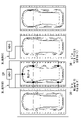
- FIG. 7 is a diagram showing an embodiment of a process of preparing charging for an electric vehicle of the present invention applied to a non-parallel type parking lot.
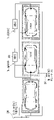
- FIG. 8 is a diagram showing an embodiment of a process of preparing charging for an electric vehicle of the present invention applied to a parallel type parking space.
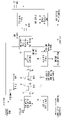
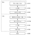
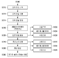
- 9 and 10 are operational flowcharts illustrating an example of a method of controlling opening and closing of a charging port executed in a charging manipulator or a charging system according to an embodiment of the present invention.
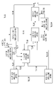
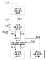
- 11 and 12 are state diagrams illustrating an example of a method of controlling opening and closing of a charging port executed in a charging manipulator or a charging system according to an embodiment of the present invention.
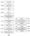
- FIG. 13 and 14 are operational flowcharts illustrating an example of a method of controlling opening and closing of a charging port executed in a charging manipulator or a charging system according to an embodiment of the present invention.
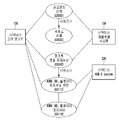
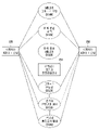
- 15 to 17 are diagrams illustrating an example of a protocol for controlling opening and closing of a charging port executed in a charging manipulator or a charging system according to an embodiment of the present invention.
- FIG. 18 is a diagram showing details of an embodiment of step S1000 in FIG. 15 .
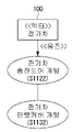
- FIG. 19 is a diagram showing details of an embodiment of step S1112 in FIG. 13 .
- FIG. 20 is a diagram showing details of an embodiment of step S1114 in FIG. 13 .
- FIG. 21 is a diagram showing details of an embodiment of steps S1120 and S1130 of FIG. 13 .
- FIG. 22 is a diagram showing details of an embodiment of steps S1230 and S1240 of FIG. 14 .
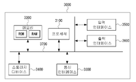
- FIG. 23 is a block diagram showing a generalized configuration of hardware for controlling opening and closing of a charging door/port in preparation for charging in connection with the electric vehicle charging system of the present invention and/or the charging manipulator.
- first, second, A, and B may be used to describe various components, but the components should not be limited by the terms. These terms are only used for the purpose of distinguishing one component from another. For example, a first element may be termed a second element, and similarly, a second element may be termed a first element, without departing from the scope of the present invention.
- the term “and/or” includes any combination of a plurality of related listed items or any of a plurality of related listed items.
- An electric vehicle may refer to an automobile defined in 49 code of federal regulations (CFR) 523.3 or the like. Electric vehicles can be used on highways and driven by electricity supplied from a vehicle-mounted energy storage device such as a rechargeable battery from a power source outside the vehicle.
- the power supply source may include a residence, a public electric service, or a generator using vehicle-mounted fuel.
- An electric vehicle may be referred to as an electric car, an electric automobile, an electric road vehicle (ERV), a plug-in vehicle (PV), a plug-in vehicle (xEV), and the like.
- xEV is BEV (plug-in all-electric vehicle or battery electric vehicle), PEV (plug-in electric vehicle), HEV (hybrid electric vehicle), HPEV (hybrid plug-in electric vehicle), PHEV (plug-in hybrid electric vehicle), etc., or may be classified.
- a plug-in electric vehicle may be referred to as an electric vehicle that recharges a vehicle-mounted primary battery by connecting to a power grid.
- a plug-in vehicle may be referred to herein as a vehicle that can be recharged through a wireless charging method without using a physical plug and socket from an electric vehicle supply equipment (EVSE).
- EVSE electric vehicle supply equipment
- Heavy duty vehicles may refer to any vehicle with four or more wheels as defined in 49 CFR 523.6 or CFR 37.3 (bus).
- Light duty plug-in electric vehicles are three or four wheels propelled by an electric motor supplied with current from a rechargeable battery or other energy device, primarily for use on public streets, roads and highways. You can refer to a vehicle with A lightweight plug-in electric vehicle can be specified with a total weight of less than 4.545 kg.
- a wireless power charging system is a system for control between a supply device (or Ground Assembly, GA) and an EV device (or Vehicle Assembly, VA), including wireless power transmission and alignment (position alignment) and communication.
- a supply device or Ground Assembly, GA
- an EV device or Vehicle Assembly, VA
- WCS wireless power charging system
- Wireless power transfer may refer to transmission of electrical power through a contactless means from an alternating current (AC) power supply network such as a utility or a grid to an electric vehicle.
- AC alternating current
- Utility is a set of systems that provide electrical energy and usually include Customer Information System (CIS), Advanced Metering Infrastructure (AMI), Rates and Revenue system, etc. can be referred to as Utilities make energy available to plug-in electric vehicles through price tags or discrete events.
- utilities can provide information on tariff rates, intervals for metered power consumption, and validation of electric vehicle programs for plug-in electric vehicles.
- Smart charging can be described as a system in which EVSEs and/or electric vehicles (including plug-in hybrid electric vehicles) communicate the vehicle charge rate or discharge rate with the power grid to optimize the grid capacity or time-to-use ratio.
- EVSEs and/or electric vehicles including plug-in hybrid electric vehicles
- Automatic charging may be defined as an operation of placing a vehicle in an appropriate position with respect to a primary charger assembly capable of transmitting power and performing conductive or inductive charging. Auto-recharge can be done after obtaining the necessary authentication and authorization.
- Interoperability can refer to a state in which components of a system relative to each other can work together to perform the desired operation of the overall system.
- Information interoperability can refer to the ability of two or more networks, systems, devices, applications or components to share and easily use information safely and effectively with little or no inconvenience to the user. .
- An inductive charging system may refer to a system that transfers energy electromagnetically in the forward direction from an electrical supply network to an electric vehicle through a transformer in which two parts are loosely coupled.
- the inductive charging system may correspond to an electric vehicle charging system.
- An inductive coupler may refer to a transformer formed of a primary device and a secondary device to transmit power through electrical isolation.
- Inductive coupling may refer to magnetic coupling between two coils.
- the two coils may refer to a primary coil/ground assembly coil and a secondary coil/vehicle assembly coil.
- a supply power circuit (SPC)/Ground assembly (GA) is a primary/ground assembly or assembly that is disposed on the infrastructure side, including the primary coil/GA coil and other suitable components.
- SPC power circuit
- Ground assembly is a primary/ground assembly or assembly that is disposed on the infrastructure side, including the primary coil/GA coil and other suitable components.
- suitable components may include at least one component for controlling impedance and resonant frequency, ferrite and electromagnetic shielding material for enhancing a magnetic path.
- an SPC or GA may include a power/frequency conversion device, an SPC controller/GA controller, and wiring from the grid required to function as a power source for a wireless charging system, and wiring between each unit and filtering circuits, housing, etc. can
- An EV power circuit (EVPC)/Vehicle assembly (VA) may refer to an assembly disposed in a vehicle including a secondary side coil/VA coil and other appropriate components.
- Other suitable components may include at least one component for controlling impedance and resonant frequency, ferrite and electromagnetic shielding material for strengthening the magnetic path.
- EVPC or VA is the wiring between each unit and filtering circuits, housing, etc. as well as the wiring of the rectifier/power converter and EVPC controller/VA controller and vehicle battery necessary to function as vehicle parts of the wireless charging system. can include
- the aforementioned SPC may be referred to as or classified as a ground assembly (GA) or the like, and similarly, the EVPC may be referred to as or classified as a vehicle assembly (VA) or the like.
- G ground assembly
- VA vehicle assembly
- the aforementioned GA may be referred to as a primary device (PD), a primary device, and the like, and similarly, a VA may be referred to as a secondary device (SD), a secondary device, and the like.
- the aforementioned GA may be referred to as a supply device, a power supply side device, and the like, and similarly, a VA may be referred to as an EV device, an electric vehicle side device, and the like.
- the primary device may be a device that provides contactless coupling to the secondary device, that is, a device external to the electric vehicle.
- a primary device may be referred to as a primary side device. When an electric vehicle receives power, the primary device can act as a power source that transmits power.
- a primary device may include a housing and all covers.
- the secondary device may be an electric vehicle-mounted device that provides contactless coupling to the primary device.
- a secondary device may be referred to as a secondary side device.
- the secondary device may transfer power from the primary device to the electric vehicle.
- the secondary device may include a housing and all covers.
- the supply power electronics may be part of the SPC or GA that adjusts the output power level to the primary coil/GA coil based on information from the vehicle.
- EV power electronics may be part of the EVPC or VA that monitors certain vehicle parameters during charging and initiates communication with the SPC or GA to control the output power level.
- the above-mentioned supply power electronics may be referred to as ground assembly electronics (GA electronics), ground assembly controller (GA controller), or primary device communication controller (PDCC), and electric vehicle EV power electronics may be referred to as VA electronics, a VA controller, or an electric vehicle communication controller (VA controller).
- G electronics ground assembly electronics
- GA controller ground assembly controller
- PDCC primary device communication controller
- VA electronics electric vehicle EV power electronics
- VA controller electric vehicle communication controller
- the magnetic gap is the highest plane of the top of the litz wire or the top of the magnetic material of the primary coil/GA coil and the lowest plane of the magnetic material of the bottom of the litz wire or the secondary coil/VA coil may refer to the vertical distance between them when aligned with each other.
- Ambient temperature may refer to the ground level temperature measured in the atmosphere of the subject subsystem not directly illuminated by sunlight.
- Vehicle ground clearance may refer to the vertical distance between a road or road pavement and the lowermost portion of a vehicle floor pan.
- Vehicle magnetic ground clearance may refer to the vertical distance between the bottom plane of the Litz wire or the insulating material of the secondary coil/VA coil mounted on the vehicle and the road pavement.
- Secondary coil surface distance/Vehicle assembly coil surface distance is the plane at the bottom of the bottom of the Litz wire or the magnetic material of the secondary coil/VA coil and the secondary coil/VA It may refer to the vertical distance between the lowermost outer surfaces of a coil. This distance may include additional items wrapped in protective covers and coil wraps.
- the aforementioned secondary coil may be referred to as a VA coil, a vehicle coil, a receiver coil, and the like, and similarly, the primary coil may be referred to as a ground assembly It may be referred to as a ground assembly coil (GA coil), a transmit coil, and the like.
- VA coil vehicle coil
- G coil ground assembly coil
- transmit coil transmit coil
- An exposed conductive component may refer to a conductive component of an electrical device (eg, an electric vehicle) that can be contacted by a person and does not normally flow electricity, but electricity may flow in the event of a failure.
- an electrical device eg, an electric vehicle
- Hazardous live component may refer to a live component capable of giving a hazardous electric shock under certain conditions.
- a live component can refer to any conductor or conductive component that is electrically energized in its primary use.
- Direct contact may refer to contact of a living being, a person.
- Indirect contact may refer to a person contacting an exposed, conductive, live active component due to an insulation failure (see IEC 61140).
- Alignment may refer to a procedure for finding a relative location of a secondary device with respect to a primary device and/or a procedure for finding a relative location of a primary device with respect to a secondary device for prescribed efficient power transmission.
- alignment may refer to positional alignment of a wireless power transmission system, but is not limited thereto.
- Pairing may refer to a procedure in which a vehicle (electric vehicle) is associated with a single dedicated ground assembly (primary device) arranged to be capable of transmitting power.
- pairing may include a procedure for associating a charging spot or a specific SPC/ground assembly with an EVPC/vehicle assembly controller.
- Correlation/Association may include a procedure for establishing a relationship between two peer communication entities.
- Command and control communication may refer to communication between an electric vehicle power supply and an electric vehicle that exchanges information necessary for initiating, controlling, and terminating a wireless power transfer process.
- High level communication can handle all information beyond that covered by command and control communication.
- a data link of high level communication may use power line communication (PLC), but is not limited thereto.
- PLC power line communication
- Low power excitation may refer to, but is not limited to, activating an electric vehicle to detect a primary device to perform precise positioning and pairing, and vice versa.
- SSID Service set identifier
- BSS basic service set
- APs access points
- terminal/station equipment that want to use a specific wireless LAN can use the same SSID.
- Devices that do not use a unique SSID cannot join the BSS. Since the SSID appears in plain text, it may not provide any security features to the network.
- ESSID Extended service set identifier
- a basic service set identifier is usually 48 bits and is used to identify a specific basic service set (BSS).
- BSSID may be a medium access control (MAC) of an AP device.
- MAC medium access control
- the BSSID can be generated with an arbitrary value.
- the charging station may include one or more ground assemblies and one or more ground assembly controllers that manage the one or more ground assemblies.
- the ground assembly may include at least one wireless communicator.
- a charging station may refer to a place having at least one ground assembly installed in a home, office, public place, road, parking lot, or the like.
- association is a term meaning a procedure for establishing wireless communication between an electric vehicle communication controller (EVCC) and a supply equipment communication controller (SECC) that controls a charging infrastructure.
- EVCC electric vehicle communication controller
- SECC supply equipment communication controller
- FIG. 1 is a diagram illustrating an example of a charging process for an electric vehicle to which an embodiment of the present invention is applied.
- an electric vehicle charging process may be performed by at least one component of an electric vehicle 100 and a charging station 200, and power is supplied to the electric vehicle 100 wired or wirelessly. can be used for transmission.
- the electric vehicle 100 may include a hybrid vehicle having both an electric motor and a general internal combustion engine, and may be used not only in automobiles but also in motorcycles, carts, may include scooters and electric bicycles.
- the electric vehicle 100 may generally be defined as a vehicle that supplies current induced from a rechargeable energy storage device such as the battery 120 as an energy source for an electric motor, which is a power unit.
- the electric vehicle 100 may include a power receiving device/pad 110 including a receiving coil to charge the battery 120 wirelessly, and a plug connector to charge the battery 120 by wire. may also include In this case, the electric vehicle 100 capable of charging the battery 120 by wire may be referred to as a plug-in electric vehicle (PEV).
- PEV plug-in electric vehicle
- the charging station 200 may be connected to a power grid 300 or a power backbone, and an AC power transmission device/pad 210 including a transmission coil is provided through a power link. (AC) or direct current (DC) power can be provided.
- AC AC
- DC direct current
- the charging station 200 may communicate with a power grid 30 or an infrastructure management system or infrastructure server that manages the power grid through wired or wireless communication, and performs wireless communication with the electric vehicle 100. can do.
- wireless communication may include Bluetooth, zigbee, cellular, wireless local area network, and the like.
- the charging station 200 may be located in various places, such as a parking lot attached to the house of the owner of the electric vehicle 100, a parking area for charging an electric vehicle at a gas station, a shopping center or a parking area at a workplace.
- the power receiving device/pad 110 of the electric vehicle 100 transmits an energy field by the power transmitting device/pad 210.
- the transmission coil of the power transmission device/pad 210 and the reception coil of the power reception device/pad 110 may interact or be coupled to each other.
- electromotive force is induced in the power receiving device/pad 110, and the battery 120 may be charged by the induced electromotive force.
- all or part of the charging station 200 and the power transmission device/pad 210 may be referred to as a power supply circuit (SPC) or a ground assembly (GA), and the SPC or ground assembly is defined above. meaning can be referenced.
- SPC power supply circuit
- GA ground assembly
- EVPC EV power circuit
- VA vehicle assembly
- FIG. 2 is a conceptual diagram of an example of a charging system for an electric vehicle to which an embodiment of the present invention is applied.
- an electric vehicle charging system may include, but is not limited to, a conductive charging system using a cable or a non-contact wireless power transmission system.
- An electric vehicle charging system can be basically defined as a system for charging the battery 120 mounted in the electric vehicle 100 using power from a grid 300 of commercial power or an energy storage device. The system may have various forms depending on the type of electric vehicle.
- SAE TIR J2954 is an industry-standard specification guideline that defines acceptance criteria for interoperability, electromagnetic compatibility, minimum performance, safety, and testing for wireless charging of light-duty electric and plug-in electric vehicles. is establishing It will be readily understood by those skilled in the art that similar guidelines may apply to wired charging systems.
- WCS Wireless Communication System
- J2954 represents an example of a wireless charging system
- a utility interface includes a utility interface, a high-frequency power inverter, a coupling coil, a rectifier, a filter, an optional regulator, and a vehicle energy charging/storage system and a power inverter connected to the utility. It can consist of inter-communication.
- the utility interface is similar to a conventional EVSE connection to single- or three-phase AC power. It will be readily understood by those skilled in the art that this basic configuration can also be applied to a wired charging system.
- Wired/wireless charging systems for electric vehicles can be largely classified into the following three types.
- VA coil with rectification, filtering components (21) and charging control power electronics (22) for regulation/safety/shutdown if necessary, and communication link (23) with base station side
- 3 and 4 are conceptual diagrams for x, y, and z axes specified in SAE J2954 applicable to an embodiment of the present invention.
- the forward direction or the front-back direction of the vehicle can be defined as the +/-X axis direction, and in one embodiment of the present invention, shown in FIGS. 3 and 4 -X axis direction can be defined as
- the driver side for left hand side vehicle or the left and right sides of the vehicle may be defined as the +/-Y axis direction, and in one embodiment of the present invention, as shown in FIGS. 3 and 4, -Y Axis direction can be defined.
- the up or down direction of the vehicle can be defined as the z-axis.
- ACD-S arm-side type robot charging system
- ACD-U Underbody
- ACD-S Advanced Driver Assistance Device
- ISO 15118-8 an international standard related to electric vehicle charging wireless communication, allows vehicles to be connected to charger APs rather than general APs through the MAC Frame's VSE (Vendor Specific Element) Field, which corresponds to the second layer of OSI 7 Layer.
- VSE Vehicle Specific Element
- WPT wireless power transfer
- ACD automatic connection device
- the vehicle cannot know whether the corresponding charger provides proper positioning and pairing methods only with the VSE field information of the charger.
- PPD Packeting and Positioning Device
- VSE field of WLAN does not contain detailed information such as maximum charging power
- a charging station where one SECC and multiple EVSEs coexist may prevent users from properly connecting to the charger they want to actually charge.
- a positioning procedure must be performed for precise alignment between the vehicle and the EVSE. or it becomes impossible to charge.
- a procedure is required to check whether a physical connection with the EVSE to be connected is possible. If the vehicle cannot physically connect to the EVSE to be charged, charging cannot proceed, so after WLAN association, the vehicle and Pairing procedures must be performed between EVSEs.
- P2PS Point to Point Signal
- ACD automatic connection device
- the present invention provides an accurate positioning, aligning, pairing, and mating procedure between the charging manipulator 220 for the electric vehicle 100 and the charging door/port 130 of the electric vehicle 100, and in this process, the charging manipulator 220 and We propose a procedure for identifying each other's type between the charging doors/ports 130 and/or selecting an EVSE suitable for charging the charging doors/ports 130.
- the power (Psrc) supplied from the power grid is AC power during the charging process for the electric vehicle 100, an AC/DC converter that converts it into DC power and a low-frequency converter that converts the DC power into power of an operating frequency suitable for wireless charging (or LF converter).
- the operating frequency may be determined to be located between, for example, 80 to 90 kHz, but is not limited thereto.
- Power transfer may be performed from the transmitting coil/primary coil L1 to the receiving coil/secondary coil L2, and at this time, the resonance frequencies of the transmitting coil L1 and the receiving coil L2 are different from each other. It may be similar or identical, and the receiving coil L2 may be located in a short distance to the electromagnetic field generated by the transmitting coil L1.
- the transmitting coil L1 may be included in the power transmitting device/pad 210 of FIG. 1
- the receiving coil L2 may be included in the power receiving device/pad 110 of FIG. 1
- the transmitting coil may be referred to as a primary coil or a ground assembly coil (GA coil)
- the receiving coil may be referred to as a secondary coil or a vehicle assembly coil (VA coil). Therefore, positioning between the power transmission device/pad 210 and the power reception device/pad 110 or positioning between the electric vehicle 100 and the power transmission device/pad 210 is also an important factor.
- Positional alignment between the power transmission device/pad 210 in FIG. 1 and the power reception device/pad 110 built into the electric vehicle 100 may correspond to the previously described term alignment, and thus, SPC It may be defined as positional alignment between /GA and EVPC/VA, and is not limited to positional alignment between the power transmitter/pad 210 and the power receiver/pad 110.
- the x-axis may indicate the forward and backward directions of the vehicle
- the y-axis may indicate the left and right directions of the vehicle
- the z-axis may indicate the up and down directions of the vehicle.
- FIG. 6 is a diagram showing a position where a charging port of an electric vehicle 100 to which an embodiment of the present invention is applied can be disposed.
- a charging port can be placed in an electric vehicle 100
- a front bumper 140, a front fender panel 150, and a rear fender panel ) 160 and the like are illustratively shown.
- each charging port is a vehicle internal switch type in which a switch capable of opening and closing the door is disposed inside the vehicle, and a switch capable of opening and closing the door from the outside of the vehicle is disposed. It can be divided into a vehicle external switch type, which can open and close the door from the outside of the vehicle, and a push door type that operates by pressing pressure.
- a switch capable of opening and closing the charging door/port is disposed near the driver's seat inside the vehicle, and the driver or passenger can open and close the charging door/port by manipulating the switch.
- a switch capable of mechanically opening and closing the charging door/port is disposed outside the vehicle, and may generally be disposed near the charging door/port.
- the external switch may be manually operated or disposed at a predetermined distance from the charging door/port.
- the push door type is a modified type of the vehicle exterior switch type, and the push switch may be disposed inside the charging door/port.
- the push switch may be operated manually or mechanically.
- the inlet cover may be made of a plastic or rubber component for insulation.
- the ACD-S charging manipulator 220 shown in FIG. 5 In order for the ACD-S charging manipulator 220 shown in FIG. 5 to open and close the charging door/port, it is necessary to identify the type of charging door/port or the type of inlet cover. For example, when the charging door/port is opened and closed by a switch inside the vehicle, the charging manipulator 220 cannot open the charging door/port from the outside, and the charging door/port can be opened by the driver or passenger's switch operation. there is. In this case, the charging manipulator 220 uses wired/wireless communication with the electric vehicle 100 so that the charging manipulator 220 is close to the charging door/port for charging, and instructs the user inside the vehicle to open the charging door/port. You can send messages as requested.
- the charging manipulator 220 may open and close the charging door/port when a specific condition is met. If the charging manipulator 220 has an appropriate size and shape to operate an external switch and can provide an adequate force through precise manipulation, the charging manipulator 220 can open the charging door/port from the outside of the vehicle. will be able to open and close.
- the charging manipulator 220 may further include a separate effector small enough to open and close an external switch in addition to a port for charging. At this time, the size of the separate effector may be designed to be small enough to operate only an external switch without affecting other mechanisms.
- the charging manipulator 220 can provide an appropriate force, the charging door/port can be opened and closed from the outside of the vehicle.
- the charging manipulator 220 When the inlet cover is disposed separately and the cover switch capable of opening and closing the inlet cover is disposed, the charging manipulator 220 has a tip of a sufficiently small size to operate only the cover switch without affecting other mechanisms, and The inlet cover can be opened and closed when force is applied to operate the cover switch.
- the charging manipulator 220 has a structure that can open and close the inlet cover, for example, a structure that can change a clamp structure or clamp type. can exchange clamp type), the inlet cover can be opened and closed.
- FIG. 7 is a diagram showing an embodiment of a process of preparing charging for an electric vehicle of the present invention applied to a non-parallel type parking lot.
- the positioning of the manipulator should take precedence over opening the EV charging door/port. .
- each country has different laws regarding parking and different sizes of parking lots are regulated.
- a parallel type parking space has a width of 2.0 m and a length of 6.0 m, and the interval between individual parking space sections is specified as 0.15.
- a non-parallel type parking space has a width of 2.3 m and a length of 5.0 m, and the spacing between individual parking space sections is specified as 0.15 m.
- the charging manipulator 220 must be positioned in an appropriate position before charging the electric vehicle 100, which prevents unwanted accidents such as collision with the moving manipulator 220 while the charging door/port of the vehicle is open. Also needed for It may be required that the position of the charging manipulator 220 be determined by considering the position of the charging door/port and the direction in which the charging door/port is opened.
- the process of determining the location of the charging manipulator 220 for charging the electric vehicle 100 is the position of the charging door/port of the electric vehicle 100, the manipulator 220 is the electric vehicle 100 It may be executed based on at least one of the movable distance 230 of the manipulator between vehicles related to whether the vehicle can move between vehicles and the movable distance 240 of the charging door (after opening) of the electric vehicle 100.
- the position of the manipulator 220 may be determined to be sufficiently spaced in consideration of the protruding size when the charging door is opened for charging.
- the process of determining the position of the charging manipulator 220 for charging the electric vehicle 100 may be executed assuming the following various cases.
- the charging manipulator 220 determines whether the distance obtained by subtracting the movable distance 240 of the charging door of the electric vehicle 100 from the movable distance 230 of the manipulator between vehicles is greater than a threshold value, and then moves to the side of the charging door.
- the minimum movable distance of the arm of the manipulator 220 may be defined assuming that adjacent vehicles on the left and right sides of the vehicle are not parked crookdedly or cross-over (in opposite directions). For example, if the width of the arm of the manipulator 220 is less than 2 cm, the minimum movable distance may be defined as 2 cm.
- FIG. 8 is a diagram showing an embodiment of a process of preparing charging for an electric vehicle of the present invention applied to a parallel type parking space.
- the distance between individual parking space sections in a parallel-type parking space is 50 cm, but in France it may be 0 cm.
- the manipulator 220 moves between vehicles while the charging door/port of the electric vehicle 100 is open, the space will be more insufficient. Therefore, it is preferable to determine the size of each section of the parking space by assuming this case. However, if the space is not sufficiently provided, it may be required to calculate a route for the manipulator 220 to approach the charging door/port considering whether the charging door/port of the surrounding vehicle or the vehicle to be charged is open.
- the charging manipulator 220 needs to be positioned in an appropriate position before charging the electric vehicle 100, which prevents collision with the moving manipulator 220 while the charging door/port of the vehicle is open. It is also necessary to prevent accidents. It may be required that the position of the charging manipulator 220 be determined by considering the position of the charging door/port and the direction in which the charging door/port is opened.
- the process of determining the position of the charging manipulator 220 for charging the electric vehicle 100 is the position of the charging door/port of the electric vehicle 100
- the manipulator 220 is the electric vehicle 100 It may be executed based on at least one of the movable distance 230 of the manipulator between vehicles related to whether the vehicle can move between vehicles and the movable distance 240 of the charging door (after opening) of the electric vehicle 100.
- the position of the manipulator 220 may be determined to be sufficiently spaced in consideration of the protruding size when the charging door is opened for charging.
- the process of determining the position of the charging manipulator 220 for charging the electric vehicle 100 may be executed assuming the following various cases.
- the charging manipulator 220 In parallel parking as shown in FIG. 8 and when the charging door is located on the front bumper side, when an obstacle, wall, or other vehicle is located right next to the charging door of the electric vehicle 100, the charging manipulator 220 operates on the charging door/ Being located close to the port can be problematic. Even at this time, the charging manipulator 220 determines whether or not a distance obtained by subtracting the movable distance 240 of the charging door of the electric vehicle 100 from the movable distance 230 of the manipulator between vehicles is greater than a threshold value, and moves to the side of the charging door. Mobility may be required.
- Moving the ACD-S charging manipulator 220 through or close to a vehicle while the vehicle's charging door/port is open may damage the vehicle's charging door.
- the charging manipulator 220 is moved to be located near the charging door of the vehicle and the charging door of the vehicle is opened while the manipulator 220 is stopped.
- the moving manipulator 220 may be required to monitor movements of passengers around the vehicle and drivers/passengers getting off the vehicle, and to move in consideration of their safety. For example, when the manipulator 220 moves in front of a vehicle door, the act of opening the door for the driver/passenger to get off, the act of the driver/passenger getting off, and the act of moving after getting off will all be considered for safety. may be requested
- the movement path of the manipulator 220 may be required to be calculated/determined in consideration of a plurality of safety-related factors.
- 9 and 10 are operational flowcharts illustrating an example of a method of controlling opening and closing of a charging port executed in a charging manipulator or a charging system according to an embodiment of the present invention.
- the charging manipulator 220 When the electric vehicle 100 provides a function to automatically open the charging door/port and inlet after parking, the charging manipulator 220 directly opens the charging door/port and inlet to the electric vehicle 100 without opening the charging door/port and inlet. You can ask to open an inlet.
- the electric vehicle 100 side may detect whether the charging door/port and inlet are opened using a separate sensor, and the charging manipulator 220 may detect whether the charging door/port and inlet are opened using an image sensor or the like. In addition, the charging manipulator 220 and the electric vehicle 100 can check whether information (opening and closing of the charging door/port and inlet) matches each other.
- Whether the charging manipulator 220 closes the charging door/port and inlet may be determined depending on whether the electric vehicle 100 provides a function for automatically closing the charging door/port and inlet after the charging of the electric vehicle 100 is completed.
- the charging manipulator 220 needs to proceed with preparation for charging, a charging process, and post-processing after charging in a state in which it is identified whether the charging door/port and the inlet are integrated.
- the electric vehicle 100 provides the function of opening and closing the charging door/port and inlet, whether the electric vehicle 100 can automatically open and close the charging door/port and inlet by the internal controller, or whether the user (driver or passenger) Since the role of the internal controller of the electric vehicle 100 is different depending on whether the charging door/port and inlet can be opened and closed according to the command of the electric vehicle 100 according to various embodiments of the present invention, the sensor and the charging manipulator 220 of the electric vehicle 100 ) side, a process of identifying the open/closed state of the charging door/port and/or inlet may be required.
- the charging manipulator 220 opens the charging door/port and/or inlet before charging, and opens the charging door/port and/or inlet after charging is completed. /or it may be desired to have the ability to close the inlet.
- the electric car 100 and the charging manipulator 220 may partially or complement each other to open and close the charging door/port and/or inlet.
- the electric car 100 may provide a function of opening the charging door/port and/or inlet
- the charging manipulator 220 may provide a function of closing the charging door/port and/or inlet.
- the charging manipulator 220 When the charging manipulator 220 provides the ability to open or close the charging door/port and/or inlet, the charging manipulator 220 applies an appropriate or appropriate force to prevent damage to the vehicle. It may be required to be controlled to provide.
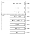
- preparation and docking processes may be required before reaching the charging process (S1200) of the electric vehicle 100.
- the preparation process may include communication setup/association between the electric vehicle 100 and the charging system/manipulator 220 (S1010), pairing (S1020), and service selection (S1030).
- the docking process includes device positioning (S1110) between the electric vehicle 100 and the charging system/manipulator 220, charging door/port opening (S1120), mating (S1130), and connection check (S1150). can do.
- the mating (S1130) process may mean mechanical coupling between the charging effector of the manipulator 220 and the inlet of the charging port.
- the connection check (S1150) process may refer to a check for an electrical or mechanical connection.
- charging preparation and docking steps are performed by the procedure shown in FIG. 9, whereas in an environment where communication support is insufficiently provided, as shown in FIG.
- the preparation of the charge and the docking steps can be done as a procedure.
- 11 and 12 are state diagrams illustrating an example of a method of controlling opening and closing of a charging port executed in a charging manipulator or a charging system according to an embodiment of the present invention.
- FIGS. 11 and 12 may be diagrams showing states and procedures defined by, for example, the IEC-TC69-WG14_N040 document. At least part of FIGS. 11 and 12 may be diagrams showing states and procedures that are not defined in standard documents.
- Some of the protocols shown in FIGS. 11 and 12 may be protocols corresponding to charging preparation and charging process when communication support is not provided. Another part of the protocol shown in FIGS. 11 and 12 may be a protocol corresponding to charging preparation and charging process when communication support is provided.
- the system of the manipulator 220 or the EVSE may change from the system OFF state (ACD_S_OFF) (S2110) to the system ON state (ACD_S_ON) (S2120) based on the protocol of the TS_01 standard.
- the system may change from the system ON state (S2120) to the system OFF state (S2110) based on the protocol of the TS_02 standard.
- the system may change from the system ON state (S2120) to a session initiated state (ACD_S_SI) (S2130) based on the protocol of the TS_03 standard.
- the system may change from the session start state (S2130) to the system ON state (S2120) based on the protocol of the TS_04 standard.
- the system may change from the session initiation state (S2130) to the charging door (port) open state (ACD_S_DO) (S2140) based on the protocol of the TS_C standard.
- the TS_C protocol may be a protocol for transmitting and receiving a command and/or request to open a charging door (port).
- the system may change from the charging door (port) open state (S2140) to the docking standby state (ACD_S_AD) (S2150) based on the protocol of the TS_D standard.
- the TS_D protocol may be a protocol for transmitting and receiving commands and/or requests that initiate more precise alignment between the manipulator 220 and the charging inlet.
- the system When communication support capable of executing the TS_C and/or TS_D standard protocols is not provided or when the automatic or semi-automatic charging door opening/closing function is not provided, the system establishes a session start state (S2130) based on the TS_05 standard protocol. ) to a docking standby state (S2150).
- the system may change from the docking standby state (S2150) to the idle state (ACD_S_IDLE) (S2210) based on the protocol of the TS_06 standard.
- the system may change from an idle state (S2210) to a power transfer active state (ACD_S_PTA) (S2220) based on the protocol of the TS_07 standard.
- the system may change from the power transfer active state (S2220) to the power transfer state (ACD_S_PT) (S2230) based on the protocol of the TS_16 standard.
- the TS_16 standard may be a protocol for transmitting and receiving commands and/or requests for power transmission after it is confirmed that the position alignment (S1110), mating (S1130), and connection check (S1150) processes for power transmission have proceeded without problems. .
- the system may change from the power transmission state (S2230) to the power transmission active state (S2220) based on the protocol of the TS_17 standard.
- the protocol of the TS_17 standard may be a protocol for transmitting and receiving a command and/or request to terminate power transmission after it is confirmed that the charging process (S1200) is completed.
- the TS_17 standard protocol may be a protocol for transmitting and receiving a command and/or request to terminate power transfer due to an interruption during the charging process (S1200).
- the system may change from the power transfer active state (S2220) to the standby state (ACD_S_STBY) (S2240) based on the protocol of the TS_14 standard. Based on the protocol of the TS_15 standard, the system may return from the standby state (S2240) to the power transmission active state (S2220).
- the protocol of the TS_14 standard may include a protocol for transmitting and receiving a command and/or request to wait when the protocol of the TS_16 standard is not satisfied in the power transfer active state (S2220).
- the protocol of the TS_15 standard may include a protocol for transmitting and receiving a command and/or request for periodically or aperiodically testing the protocol of the TS_16 standard in the standby state (S2240).
- the system may return from the power transfer active state (S2220) to the idle state (S2210) based on the protocol of the TS_08 standard.
- the protocol of the TS_08 standard may include a protocol for transmitting and receiving a command and/or request to change to an idle state (S2210) when power transmission is complete or power transmission fails.
- the system may change from an idle state (S2210) to a session terminated occupied state (ACD_S_STO) (S2160) based on the protocol of the TS_09 standard.
- the system may change from the session end occupied state (S2160) to the charging door (port) closed state (ACD_S_DC) (S2170) based on the protocol of the TS_A standard.
- a protocol of the TS_A standard may be a protocol for transmitting and receiving a command or request to close a charging door (port).
- the system may change from the charging door (port) closed state (S2170) to the system ON state (S2120) based on the protocol of the TS_B standard.
- the protocol of the TS_B standard may be a protocol for transmitting and receiving information, commands, and/or requests for the electric vehicle 100 to depart from the EVSE.
- the system may change from the session end occupied state (S2160) to the system ON state (S2120) based on the protocol of the TS_11 standard.
- the system may change from the session end occupation state (S2160) to the session start state (S2130) based on the protocol of the TS_10 standard.
- the system may change from the idle state (S2210) to the sleep mode state (ACD_S_SLP) (S2250) based on the protocol of the TS_12 standard.
- the system may change from the sleep mode state (S2250) to the session end occupancy state (S2160) based on the protocol of the TS_13 standard.
- the system may change to an exception handling state (ACD_S_ERR) (S2180).
- the system may change from the exception handling state (S2180) to the system OFF state (S2110) based on the protocol of the TS_E_01 standard.
- the system may change from the exception processing state (S2180) to the system ON state (S2120) based on the protocol of the TS_E_02 standard.
- the system may change from the exception handling state (S2180) to the session initiation state (S2130) based on the protocol of the TS_E_03 standard.
- the system may change from the exception processing state (S2180) to the idle state (S2210) based on the protocol of the TS_E_04 standard.
- 13 and 14 are operational flowcharts illustrating an example of a method of controlling opening and closing of a charging port executed in the charging manipulator 220 or the charging system 210 according to an embodiment of the present invention.
- a communication setup step (S1010) may be executed between the charging manipulator 220/charging system 210 and the electric vehicle 100.
- the vehicle positioning step (S1014) may be executed.
- a process for the electric vehicle 100 to select the charging manipulator 220/charging system 210 may precede the vehicle positioning step (S1014).
- the selection process is executed before the communication setup step (S1010) and the communication setup step for the selected charging system 210 (S1010) may be executed.
- the manipulators when one charging system 210 is connected to a plurality of manipulators and one of the plurality of manipulators is required to be selected, the manipulators after the communication setup step (S1010) Any one of them may be selected, and the vehicle may be positioned to a position where charging is possible with the selected manipulator 220 (S1014). According to another embodiment of the present invention, the charging system 210 and/or the manipulator 220 may be selected before the communication setup step (S1010).
- a pairing step (S1020) between the manipulator 220/charging system 210 and the electric vehicle 100 may be executed.
- a service selection step (S1030) may be executed.
- the process of selecting the manipulator 220 may be executed after the pairing step (S1020) or after the service selection step (S1030).
- a positioning setup step (S1112) of the manipulator 220 may be executed.
- Step S1112 may be executed based on the type of manipulator 220, such as ACD-S or ACD-U.
- a positioning step (S1114) of the manipulator 220 may be executed.
- the step of positioning the manipulator 220 (S1114) may be a process of manipulating the manipulator 220 to be positioned very close to the charging door/port.
- the charging door opening step (S1120) is the step of automatically opening the charging door by the electric vehicle 100 according to the performer (S1122), the step of opening the charging door by the manipulator 220 (S1124), the user or a third subject It can be executed as any one of the steps of manually opening the charging door (S1126).
- the inlet cover opening step (S1130) may be executed.
- the inlet cover is automatically opened by the electric vehicle 100 according to the performer (S1132), the manipulator 220 opens the inlet cover (S1134), and the user or a third subject Thus, the inlet cover may be manually opened as one of the steps (S1136).
- the inlet cover opening step (S1130) may be merged with the charging door opening step (S1120) or may be omitted.
- a mating step (S1140) may be executed after the charging door opening step (S1120) and/or the inlet cover opening step (S1130).
- the mating step (S1140) may be understood as a process in which the manipulator 220 is coupled to and connected to the inlet.
- a start power transfer step (S1210) may be executed.
- a power transfer performance step (S1212) may be executed.
- a power transmission stop step (S1214) may be executed.
- a disconnect/unmating step (S1220) of the manipulator 220 may be executed.
- the inlet cover closing step (S1230) and/or the charging door closing step (S1240) may be executed.
- the inlet cover closing step (S1230) is a step of automatically closing the inlet cover by the electric vehicle 100 according to the subject (S1232), a step of opening the inlet cover by the manipulator 220 (S1234), and a user or a third subject Thus, the inlet cover may be manually opened as one of the steps (S1236).
- the charging door closing step (S1240) is a step of automatically closing the charging door by the electric vehicle 100 according to the subject (S1242), a step of closing the charging door by the manipulator 220 (S1244), a user or a third subject It can be executed as any one of the steps (S1246) of manually closing the charging door.
- the inlet cover closing step (S1230) may be merged with the charging door closing step (S1240) or may be omitted.
- a communication termination step (S1250) may be executed. After the communication termination step (S1250), the electric vehicle 100 may leave the charging spot (S1260).
- step (S1122, S1132, S1232, S1242) of automatically opening or closing the charging door and/or the inlet cover by the electric vehicle 100 it is determined that the positioning of the manipulator 220 has been completed or that the manipulator 220 has been unmated from the inlet.
- Information may be shared between the electric vehicle 100 and the manipulator 220, and commands or requests for automatic opening/closing of the charging door and/or inlet cover may be shared between the electric vehicle 100 and the manipulator 220. .
- the charging door and/or the inlet cover may be automatically opened or closed by the controller of the electric vehicle 100.
- the manipulator 220 or the electric vehicle 100 may obtain information on whether the charging door and/or the inlet cover is open or closed based on at least one sensor, and based on this information, the charging door And/or a command or request for automatic opening/closing of the inlet cover may be attempted again between the electric vehicle 100 and the manipulator 220 .
- the charging door and/or inlet Information, guidance, or notification about manual automatic opening/closing of the cover may be conveyed back to the user or a third party.
- the steps of opening or closing the charging door and/or the inlet cover by the manipulator 220 (S1124, S1134, S1234, S1244), information indicating that the positioning of the manipulator 220 has been completed or that the manipulator 220 is unmated from the inlet is displayed. It is shared between the electric vehicle 100 and the manipulator 220, and a command or request for automatic opening/closing of the charging door and/or the inlet cover may be shared between the electric vehicle 100 and the manipulator 220. Afterwards, the charging door and/or the inlet cover may be opened or closed by the manipulator 220 .
- the charging door and/or inlet A command or request for opening/closing of the cover may be shared between the electric vehicle 100 and the manipulator 220 again.
- the manipulator 220 applies appropriate force ( may be required to be precisely controlled to apply an adequate force.
- the performers of the steps of opening/closing the charging door and/or the inlet cover may be the same or different.
- Individual performers of the opening/closing steps (S1120, S1130, S1230, and S1240) of the charging door and/or inlet cover may be determined by the types of the charging door and/or inlet cover. Accordingly, types of the charging door and/or inlet cover may be identified before the opening/closing steps ( S1120 , S1130 , S1230 , and S1240 ) of the charging door and/or inlet cover are performed.
- the charging door and/or the inlet cover may be automatically opened or closed by the electric vehicle 100 (S1122, S1132, S1232, S1242).
- the charging door and/or the inlet cover may be opened or closed by the manipulator 220 (S1124, S1134, S1234, S1244).
- the charging door and/or the inlet cover may be automatically opened by the electric vehicle 100 (S1122 and S1132) and closed by the manipulator 220 (S1234 and S1244).
- 15 to 17 are diagrams illustrating an example of a protocol for controlling opening and closing of a charging port executed in a charging manipulator or a charging system according to an embodiment of the present invention.
- a step of selecting an EVSE between the electric vehicle 100 and the autonomous driving system 150 may be executed.
- a service selection step (S1030) may be executed.
- the service selection step (S1030) may be performed using the execution result of the EVSE selection step (S1000).
- the electric vehicle 100 receives information about a plurality of EVSEs, the movable range and operating range of the manipulator associated with each EVSE, and the function of the manipulator (charging door and/or inlet cover) This can be done by selecting an EVSE with a suitable manipulator based on its ability to open and close.
- the plurality of EVSEs may periodically or non-periodically broadcast information about charging infrastructure.
- Information on the charging infrastructure may include information on the location and function of the EVSE, the type of charger associated with the EVSE, whether a manipulator exists, and information on the function of the manipulator and its range of motion/movement.
- a plurality of EVSEs may broadcast their own information only when one or more electric vehicles are detected nearby or entering a parking space including a charging facility. EVSE may not broadcast even if a new vehicle enters in a state where both the charger and the manipulator are occupied by the vehicle, or may broadcast with a notification notifying that the current vehicle is occupied.
- a precise positioning step (S1040) of the electric vehicle 100 may be executed between the electric vehicle 100 and the autonomous driving system 150.
- a positioning setup step of the ACD-S manipulator 220 between the electric vehicle 100 and the ACD-S system or manipulator 220 (S1112) may be executed.
- the positioning setup step (S1112) of the ACD-S manipulator 220 may be performed using the execution result of the precise positioning step (S1040) of the electric vehicle 100.
- the positioning step (S1114) of the ACD-S manipulator 220 may be executed.
- the electric vehicle 100 may open the charging door (S1122). Subsequently, the electric vehicle 100 may open the inlet cover (S1132).
- FIG. 17 a workflow assuming the case of an EVSE 210 including an ACD-U system 250 in addition to the ACD-S system 220 is shown.
- the ACD-S/U mechanics docking step (S1144) may be executed by at least one of the ACD-S system 220 and the ACD-U system 250.
- a power connection check step (S1150) may be executed by at least one of the ACD-S system 220 and the ACD-U system 250.
- the ACD-S/U power transmission step (S1200) may be executed by the EVSE 210.
- the mechanics undocking step (S1220) may be executed by at least one of the ACD-S system 220 and the ACD-U system 250.
- the inlet cover closing step (S1230) and the charging door closing step (S1240) may be executed.
- FIGS. 6 to 16 have been described centering on the ACD-S system, but as shown in FIG. 17, in another embodiment of the present invention, power transmission preparation and power based on the ACD-U system transfer can be performed.
- the ACD-S system or ACD-U system is only an example of the currently known charging specifications of electric vehicles, and other embodiments of the present invention are not limited to the ACD-S system or the ACD-U system but are related to various electric vehicle charging specifications.
- Preparing the charging process for the electric vehicle positioning, opening of the charging door/port and/or inlet cover, docking/mating
- executing the charging process post-processing after completion of the charging process (unmating/undocking, charging) closing of doors/ports and/or inlet covers, leaving the vehicle).
- FIG. 18 is a diagram showing details of an embodiment of step S1000 in FIG. 15 .
- the content disclosed in FIG. 18 is a process for the electric vehicle 100 to select a charging spot. It is assumed that communication between the electric vehicle 100 and a supply equipment communication controller (SECC) is not established. When the process disclosed in FIG. 18 is executed, as a result, communication between the electric vehicle 100 and the SECC is established, and information on a charging spot selected by the electric vehicle 100 may be provided.
- SECC supply equipment communication controller
- step S1000 basic scenarios, alternatives, and exceptions may be defined in addition to the above purpose, prerequisites, and follow-up conditions with respect to step S1000.
- the basic scenario may be described with respect to a process in which the electric vehicle 100 selects a charging spot with support from the SECC.
- the basic scenario may start from a process in which the electric vehicle 100 moves into the range of the communication system.
- the electric vehicle 100 may initiate communication with the EVSE or the SECC of the charging site.
- service selection can be applied.
- An available EVSE or ACD-S/U system may be provided to a user (customer) of the electric vehicle 100 through a power supply system (SE) site or an EV information system.
- SE power supply system
- selection of a compatible EVSE or ACD-S/U system may be performed prior to entry into the parking region by a backend Internet service or other system.
- compatibility may be confirmed as part of the negotiation process.
- Exceptions include communication failure, vehicle positioning failure, pairing signal unavailable, and pairing not being confirmed.
- FIG. 19 is a diagram showing details of an embodiment of step S1112 in FIG. 13 .
- the content disclosed in FIG. 19 is a protocol in which at least one entity among the electric vehicle 100, the electric vehicle communication controller (EVCC), the ACD-S/U system, and the SECC participates, and the ACD-S/U manipulator positioning setup step (S1112).
- the purpose of the content disclosed in FIG. 19 may be to define a use case for exchanging location and type information of the charging door of the electric vehicle 100.
- EVs can also be precondition to complete parking and not moving.
- a subsequent condition obtained by executing step S1112 is that the ACD-S/U manipulator is ready to perform positioning.
- a basic scenario may define an operation of exchanging information required to open a charging door and an inlet cover between an EV and an ACD-S/U system.
- the exchangeable information may include information about the location and size of the EV charging door, the opening direction of the charging door, and how the door and inlet cover are opened.
- Information on how to open the door and inlet cover is information on whether the door and/or cover can be opened automatically by the EV, whether it can be opened by the ACD-S/U manipulator, or whether it must be opened manually by a human. can include
- it may further include information necessary for the manipulator to be located in a safe place to avoid a collision while the charging door is open or the manipulator is moving.
- Exceptions include communication failure, vehicle positioning failure, pairing signal unavailable, and pairing not being confirmed.
- FIG. 20 is a diagram showing details of an embodiment of step S1114 in FIG. 13 .
- the contents disclosed in FIG. 20 relate to the ACD-S/U manipulator positioning step (S1114) as a protocol in which at least one entity among EV, EVCC, ACD-S/U system, and SECC participates.
- the purpose of the content disclosed in FIG. 20 may be to define a use case for the manipulator of the ACD-S/U system to be properly positioned in the EV charging door.
- manipulators of the ACD-S/U system can be understood to be properly positioned by being positioned to fully utilize the system functions.
- a precondition may be that EVCC and SECC have completed ACD-S/U manipulator positioning setup and exchanged necessary information for manipulator positioning.
- a subsequent condition may be a state in which the manipulator is positioned in front of the charging door and the EV is ready to open the charging door and inlet cover.
- a base scenario may involve moving an ACD-S manipulator near the EV charging door and positioning the manipulator so that the charging door and/or inlet cover can be safely opened by the EV or the manipulator. At this time, when the positioning of the manipulator is completed, the connector (for charging the vehicle) can be connected to the inlet.
- Exceptions include communication failure and ACD-S/U manipulator positioning failure.
- FIG. 21 is a diagram showing details of an embodiment of steps S1120 and S1130 of FIG. 13 .
- the content disclosed in FIG. 21 is a protocol in which at least one entity among EV, EVCC, ACD-S/U system, and SECC participates, and relates to opening steps (S1120 and S1130) of the charging door and the inlet cover.
- the purpose of the content disclosed in FIG. 21 may be to define a use case for opening the charging door and inlet cover of the EV.
- Prerequisites may be that communication between the EVCC and the SECC is established, and that the ACD-S manipulator is positioned around the EV charging door.
- the ACD-S manipulator or the SECC may notify the EVCC that the ACD-S manipulator is positioned near the EV charging door, and the EVCC may return a response confirming that the notification has been received.
- a subsequent condition may be preparation for connecting the connector of the ACD-S/U system to the vehicle inlet.
- the basic scenario may be a scenario in which the EV and the ACD-S/U system exchange necessary information to open the charging door and the inlet cover, and consequently secure the open state of the charging door and the inlet cover.
- Case 1 is a process in which the EV opens the door and inlet cover, and the EV may request permission to open the door to the SECC. If SECC confirms, the EV can automatically open the charging door and inlet cover. The EV can report the completion of opening the charging door and inlet cover. If SECC confirms, you can proceed with subsequent steps.
- Case 2 is a process in which the manipulator opens the door and inlet cover, and the EV requests the SECC to open the door/inlet.
- the SECC may report door/inlet opening completion.
- the EV can confirm to the SECC that the door/inlet is actually open. If SECC confirms, you can proceed with subsequent steps.
- Case 3 assumes a case where humans have to open the door and inlet cover.
- the EVCC may inform the SECC of a manual door opening process by a human. If the SECC confirms, the EV can prompt the EV user to manually open the door/inlet. EVCC may report door/inlet opening completion to SECC. If SECC confirms, you can proceed with subsequent steps.
- Exceptions include communication failure, failure to open the charging door, and failure to open the inlet cover.
- FIG. 22 is a diagram showing details of an embodiment of steps S1230 and S1240 of FIG. 14 .
- the content disclosed in FIG. 22 is a protocol in which at least one entity among EV, EVCC, ACD-S/U system, and SECC participates, and relates to closing steps (S1230 and S1240) of the charging door and the inlet cover.
- the purpose of the content disclosed in FIG. 22 may be to define a use case for closing the charging door and inlet cover of the EV.
- Prerequisites include that the ACD-S/U system has completed power transfer to the EV, that the vehicle's connector/inlet has been unlocked if locked, and that the unmating and redtracting use cases have been completed. can do.
- a subsequent condition may be the closed state of the EV inlet cover and charging door.
- the basic scenario may be a scenario in which the EV and the ACD-S/U system exchange necessary information to close the charging door and the inlet cover, and consequently ensure that the charging door and the inlet cover are closed.
- the charging door may be closed after the closing of the inlet cover is completed.
- Case 1 is a process in which the EV closes the door and inlet cover, and the EV may request permission to close the door to the SECC. If SECC confirms, the EV can automatically close the charging door and inlet cover. The EV can report charging door and inlet cover closure completion. If SECC confirms, you can proceed with subsequent steps.
- Case 2 is a process in which the manipulator closes the door and inlet cover, and the EV requests the SECC to close the door/inlet.
- the SECC may report the completion of closing of the door/inlet.
- the EV can confirm to the SECC that the door/inlet is actually closed. If SECC confirms, you can proceed with subsequent steps.
- Case 3 assumes a case where a human needs to close the door and the inlet cover.
- the EVCC may inform the SECC of a manual door closing process by a human. If the SECC confirms, the EV can prompt the EV user to manually close the door/inlet. The EVCC may report the closing completion of the door/inlet to the SECC. If SECC confirms, you can proceed with subsequent steps.
- Exceptions include communication failure, failure to close the inlet cover, and failure to close the charging door.
- FIG. 23 is a block showing a generalized configuration of hardware for controlling the opening and closing of the charging door/port 130 in preparation for charging in connection with the electric vehicle charging system 210 and/or the charging manipulator 220 of the present invention. It is also
- controller 3000 hardware that controls a sequence related to opening and closing of the charging door/port 130 may be referred to as a controller 3000 .
- the controller 3000 may be disposed on the electric vehicle 100 side, electric vehicle power supply facility (EVSE) side, or disposed on the power transmission device/pad 210 side.
- EVSE electric vehicle power supply facility
- the controller 3000 includes at least one processor 3100, a memory 3200 storing at least one command for executing the above-described operation through the processor 3100, and a communication interface 3300 connected to a network to perform communication. ) may be included.
- the controller 3000 for wireless power transmission may further include a storage device 3400 capable of storing at least one command executing the above-described operation or data generated during an execution process.
- the controller 3000 for wireless power transmission may further include an input interface 3500 and an output interface 3600 for interaction with a user.
- Each component included in the controller 3000 for wireless power transmission may be connected by a system bus 3700 to communicate with each other.
- the processor 3100 may execute a program command/instruction stored in the memory 3200, and may use a central processing unit (CPU), graphics processing unit (GPU), or according to the present invention. It may refer to a dedicated processor in which methods are performed.
- CPU central processing unit
- GPU graphics processing unit
- Each of the memory 3200 and the storage device 3400 may include at least one of a volatile storage medium and a non-volatile storage medium.
- the memory 3200 may include at least one of a read only memory (ROM) and a random access memory (RAM).
- the at least one command is a sequence capable of mutually identifying at least one of the electric vehicle 100, the electric vehicle power supply facility (EVSE), the power transmission device/pad 210, and the manipulator 220, and the electric vehicle 100 Aligning and/or pairing by wireless communication association sequence between at least two of EVSE, electric power transmission device/pad 210, and manipulator 220, mutual positioning It may include at least one of a sequence that performs pairing and a sequence that allows AC signal application so that power is transmitted after alignment and/or pairing.
- EVSE electric vehicle power supply facility
- the at least one command is a sequence of exchanging information for opening the charging door and/or inlet cover between the electric vehicle 100 and the manipulator 220, providing or requesting information necessary to actually open the charging door and/or inlet cover, Sequence of actually opening the charging door and/or inlet cover in response to a request, checking whether the charging door and/or inlet cover is actually open, report based on the check result, confirmation of the report, mating between inlet and connector, power transmission process , unmating, a sequence for closing the charging door and/or an inlet cover, and a sequence executed for the vehicle to safely leave the parking space.
- a method for controlling and operating peripheral devices to open and close the charging door/port of the electric vehicle 100 is implemented in the form of program commands that can be executed through various computer means and stored in a computer readable medium.
- the computer readable medium may include program instructions, data files, data structures, etc. alone or in combination.
- Program instructions recorded on the medium may be those specially designed and configured for the present invention or those known and usable to those skilled in computer software.
- Examples of computer-readable recording media include magnetic media such as hard disks, floppy disks and magnetic tapes, optical media such as CD-ROMs and DVDs, and magnetic media such as floptical disks.
- - includes hardware devices specially configured to store and execute program instructions, such as magneto-optical media, and ROM, RAM, flash memory, and the like.
- program instructions include high-level language codes that can be executed by a computer using an interpreter, as well as machine language codes such as those produced by a compiler.
- the hardware devices described above may be configured to act as one or more software modules to perform the operations of the present invention, and vice versa.
- a block or apparatus corresponds to a method step or feature of a method step.
- aspects described in the context of a method may also be represented by a corresponding block or item or a corresponding feature of a device.
- Some or all of the method steps may be performed by (or using) a hardware device such as, for example, a microprocessor, programmable computer, or electronic circuitry. In some embodiments, one or more of the most important method steps may be performed by such an apparatus.
- a programmable logic device eg, a field programmable gate array
- a field programmable gate array may operate in conjunction with a microprocessor to perform one of the methods described herein.
- methods are preferably performed by some hardware device.
- various types of electric vehicle charging ports, various types of electric vehicle power supply devices, and various charging methods when power is supplied from a power supply device or electric vehicle supply equipment (EVSE) to an electric vehicle Considering this, it is possible to provide a procedure for positioning between an electric vehicle and a charging manipulator, and a preparatory step for power supply.
- EVSE electric vehicle supply equipment
- an electric vehicle charging port that can correspond to various types of electric vehicle charging ports, various types of electric vehicle power supply devices, and various charging methods.
- an electric vehicle charging inlet that can correspond to various types of electric vehicle charging ports, various types of electric vehicle power supply devices, and various charging methods.
- a procedure for positioning, mating, and unmating steps after charging is completed between an electric vehicle and a charge manipulator capable of responding to various types of electric vehicle charging ports, various types of electric vehicle power supplies, and various charging methods. can provide.
Landscapes
- Engineering & Computer Science (AREA)
- Power Engineering (AREA)
- Transportation (AREA)
- Mechanical Engineering (AREA)
- Life Sciences & Earth Sciences (AREA)
- Sustainable Development (AREA)
- Sustainable Energy (AREA)
- Chemical & Material Sciences (AREA)
- Combustion & Propulsion (AREA)
- Computer Networks & Wireless Communication (AREA)
- Charge And Discharge Circuits For Batteries Or The Like (AREA)
- Electric Propulsion And Braking For Vehicles (AREA)
Abstract
Description
Claims (20)
- 충전 매니퓰레이터를 포함하는 전기차 전원 공급장치(EVSE)에 의하여 실행되는 방법으로서,상기 충전 매니퓰레이터를 전기차의 충전 도어에 대응하는 위치에 위치시키는 단계;상기 충전 도어를 열기 위한 프로토콜을 수행하는 단계;상기 충전 도어가 열렸는 지 여부를 확인하는 단계; 및상기 충전 도어의 인렛(inlet)에 상기 충전 매니퓰레이터를 결합하는 단계;를 포함하는 전기차 충전 도어의 개폐를 위한 제어 방법.
- 제1항에 있어서,상기 전기차에 대한 전력 전송 과정이 종료되면 상기 충전 매니퓰레이터를 상기 인렛으로부터 언메이팅하는 단계;상기 충전 도어를 닫기 위한 프로토콜을 수행하는 단계; 및상기 충전 도어가 닫혔는 지 여부를 확인하는 단계;를 더 포함하는 전기차의 충전 도어의 개폐를 위한 제어 방법.
- 제1항에 있어서,상기 전기차로부터 상기 충전 도어의 형태, 상기 충전 도어가 열리는 타입, 및 상기 충전 도어가 열리는 방향 중 적어도 하나 이상을 수신하는 단계;를 더 포함하는 전기차의 충전 도어의 개폐를 위한 제어 방법.
- 제1항에 있어서,상기 전기차로부터 인렛 커버가 상기 충전 도어와 독립적으로 형성되어 있는 지에 대한 정보를 수신하는 단계;를 더 포함하는 전기차의 충전 도어의 개폐를 위한 제어 방법.
- 제1항에 있어서,상기 충전 도어가 열린 것이 확인된 상태에서 상기 인렛에 상기 충전 매니퓰레이터가 결합되기 전에 상기 전기차의 인렛 커버를 열기 위한 프로토콜을 수행하는 단계; 및상기 인렛 커버가 열렸는 지 여부를 확인하는 단계;를 더 포함하는 전기차의 충전 도어의 개폐를 위한 제어 방법.
- 제2항에 있어서,상기 충전 매니퓰레이터가 상기 인렛으로부터 언메이팅된 것이 확인된 상태에서 상기 충전 도어를 닫기 위한 프로토콜을 수행하는 단계 이전에,상기 인렛 커버를 닫기 위한 프로토콜을 수행하는 단계; 및상기 인렛 커버가 닫혔는 지 여부를 확인하는 단계;를 더 포함하는 전기차의 충전 도어의 개폐를 위한 제어 방법.
- 제1항에 있어서,상기 충전 매니퓰레이터를 전기차의 충전 도어에 대응하는 위치에 위치시키는 단계는상기 충전 도어의 위치, 차량 간 거리, 상기 충전 도어가 열린 후를 가정할 때의 차량 간 거리 중 적어도 하나 이상에 기반하여 상기 충전 매니퓰레이터가 상기 충전 도어에 대응하는 위치에 대응하도록 상기 충전 매니퓰레이터의 이동 경로를 결정하는 전기차의 충전 도어의 개폐를 위한 제어 방법.
- 제1항에 있어서,상기 충전 도어를 열기 위한 프로토콜을 수행하는 단계는상기 충전 매니퓰레이터가 상기 충전 도어에 대응하는 위치에 위치하고 있음을 상기 전기차와 공유하는 단계;상기 전기차로부터 상기 충전 도어를 열기 위한 퍼미션 요청을 수신하는 단계; 및상기 전기차로부터 상기 충전 도어를 열었음을 알리는 통지를 수신하는 단계;를 포함하는 전기차 충전 도어의 개폐를 위한 제어 방법.
- 제1항에 있어서,상기 충전 도어를 열기 위한 프로토콜을 수행하는 단계는상기 충전 매니퓰레이터가 상기 충전 도어에 대응하는 위치에 위치하고 있음을 상기 전기차와 공유하는 단계;상기 전기차로부터 상기 충전 도어를 열기 위한 요청을 수신하는 단계;상기 충전 도어의 형태, 상기 충전 도어가 열리는 타입, 및 상기 충전 도어가 열리는 방향 중 적어도 하나 이상에 기반하여 상기 충전 도어를 열도록 상기 매니퓰레이터를 제어하는 단계; 및상기 전기차로부터 상기 충전 도어가 열렸음을 확인하는 통지를 수신하는 단계;를 포함하는 전기차 충전 도어의 개폐를 위한 제어 방법.
- 제1항에 있어서,상기 충전 도어를 열기 위한 프로토콜을 수행하는 단계는상기 충전 매니퓰레이터가 상기 충전 도어에 대응하는 위치에 위치하고 있음을 상기 전기차와 공유하는 단계;상기 전기차로부터 상기 충전 도어가 인간의 수동적인 조작에 의하여 열리는 프로세스를 진행 중임을 알리는 통지를 수신하는 단계; 및상기 전기차로부터 상기 충전 도어가 열렸음을 확인하는 통지를 수신하는 단계;를 포함하는 전기차 충전 도어의 개폐를 위한 제어 방법.
- 충전 매니퓰레이터를 포함하며 전기차로 전력을 전송하는 전기차 전원 공급장치(EVSE)로서,적어도 하나 이상의 명령을 저장하는 메모리;상기 적어도 하나 이상의 명령을 상기 메모리로부터 로드하여 실행함으로써 상기 충전 매니퓰레이터의 움직임을 제어하는 프로세서; 및상기 전기차로 전력을 전송하는 과정에 필요한 정보를 상기 전기차와 송수신하는 통신 인터페이스;를 포함하고,상기 프로세서는 상기 충전 매니퓰레이터를 상기 전기차의 충전 도어에 대응하는 위치에 위치시키도록 상기 충전 매니퓰레이터를 제어하고,상기 프로세서는 상기 통신부를 경유하여 상기 전기차와 통신함으로써 상기 충전 도어를 열기 위한 프로토콜을 수행하고,상기 프로세서는 상기 충전 도어가 열렸는 지 여부를 확인하고,상기 프로세서는 상기 충전 도어가 열린 상태에서 상기 충전 도어의 인렛에 상기 충전 매니퓰레이터를 결합하도록 상기 매니퓰레이터를 제어하는, 전기차 전원 공급장치(EVSE).
- 제11항에 있어서,상기 프로세서는상기 전기차에 대한 전력 전송 과정이 종료되면 상기 충전 매니퓰레이터를 상기 인렛으로부터 언메이팅하도록 상기 충전 매니퓰레이터를 제어하고,상기 통신부를 경유하여 상기 전기차와 통신함으로써 상기 충전 도어를 닫기 위한 프로토콜을 수행하고,상기 충전 도어가 닫혔는 지 여부를 확인하는,전기차 전원 공급장치(EVSE).
- 제11항에 있어서,상기 프로세서는 상기 통신부를 경유하여 상기 전기차와 통신함으로써 상기 전기차로부터 상기 충전 도어의 형태, 상기 충전 도어가 열리는 타입, 및 상기 충전 도어가 열리는 방향 중 적어도 하나 이상을 수신하는, 전기차 전원 공급장치(EVSE).
- 제11항에 있어서,상기 프로세서는 상기 통신부를 경유하여 상기 전기차와 통신함으로써 상기 전기차로부터 인렛 커버가 상기 충전 도어와 독립적으로 형성되어 있는 지에 대한 정보를 수신하는, 전기차 전원 공급장치(EVSE).
- 제11항에 있어서,상기 프로세서는 상기 충전 도어의 위치, 차량 간 거리, 상기 충전 도어가 열린 후를 가정할 때의 차량 간 거리 중 적어도 하나 이상에 기반하여 상기 충전 매니퓰레이터가 상기 충전 도어에 대응하는 위치에 대응하도록 상기 충전 매니퓰레이터의 이동 경로를 결정하는, 전기차 전원 공급장치(EVSE).
- 충전 매니퓰레이터를 포함하는 전기차 전원 공급장치(EVSE)와 통신 가능한 전기차에 의하여 실행되는 방법으로서,상기 충전 매니퓰레이터가 상기 전기차의 충전 도어에 대응하는 위치에 위치하는 지에 대한 정보를 수신하는 단계;상기 충전 도어를 열기 위한 프로토콜을 수행하는 단계;상기 충전 도어가 열렸는 지 여부를 확인하는 단계; 및상기 충전 도어에 상기 충전 매니퓰레이터가 결합되었는 지를 인식하는 단계;를 포함하는 전기차 충전 도어의 개폐를 위한 제어 방법.
- 제16항에 있어서,복수의 전기차 전원 공급장치에 대한 식별 정보를 수신하는 단계; 및상기 복수의 전기차 전원 공급장치 중 상기 충전 매니퓰레이터를 포함하는 상기 전기차 전원 공급장치(EVSE)를 선택하는 단계;를 더 포함하는 전기차 충전 도어의 개폐를 위한 제어 방법.
- 제16항에 있어서,복수의 전기차 전원 공급장치 중 상기 충전 매니퓰레이터를 포함하는 상기 전기차 전원 공급장치(EVSE)의 동작 가능 범위 내로 상기 전기차를 이동하여 주차하거나 상기 전기차를 주차하도록 사용자에게 안내하는 단계;를 더 포함하는 전기차 충전 도어의 개폐를 위한 제어 방법.
- 제16항에 있어서,상기 충전 도어를 상기 전기차가 자동으로 열 수 있는 지에 대한 정보 및 상기 충전 도어를 상기 전기차가 자동으로 닫을 수 있는 지에 대한 정보 중 적어도 하나 이상을 상기 전기차 전원 공급장치로 제공하는 단계;를 더 포함하는 전기차 충전 도어의 개폐를 위한 제어 방법.
- 제16항에 있어서,상기 충전 도어를 상기 충전 매니퓰레이터가 자동으로 열 수 있는 지에 대한 정보 및 상기 충전 도어를 상기 충전 매니퓰레이터가 자동으로 닫을 수 있는 지에 대한 정보 중 적어도 하나 이상을 상기 전기차 전원 공급장치로부터 수신하는 단계;를 더 포함하는 전기차 충전 도어의 개폐를 위한 제어 방법.
Priority Applications (3)
| Application Number | Priority Date | Filing Date | Title |
|---|---|---|---|
| CN202280049335.5A CN117615935A (zh) | 2021-07-12 | 2022-07-12 | 用于打开和关闭电动车辆充电门/端口的控制方法及供电装置 |
| EP22842427.1A EP4371804A4 (en) | 2021-07-12 | 2022-07-12 | CONTROL METHOD AND POWER SUPPLY DEVICE FOR OPENING AND CLOSING ELECTRIC VEHICLE CHARGING DOOR/PORT |
| US18/578,969 US20240317093A1 (en) | 2021-07-12 | 2022-07-12 | Control method and power supply device for opening and closing electric vehicle charging door/port |
Applications Claiming Priority (6)
| Application Number | Priority Date | Filing Date | Title |
|---|---|---|---|
| KR10-2021-0091206 | 2021-07-12 | ||
| KR20210091206 | 2021-07-12 | ||
| US202163225088P | 2021-07-23 | 2021-07-23 | |
| US63/225,088 | 2021-07-23 | ||
| KR10-2022-0085120 | 2022-07-11 | ||
| KR1020220085120A KR20230010595A (ko) | 2021-07-12 | 2022-07-11 | 전기차 충전구의 개폐를 위한 제어 방법 및 전원 공급 장치 |
Publications (1)
| Publication Number | Publication Date |
|---|---|
| WO2023287165A1 true WO2023287165A1 (ko) | 2023-01-19 |
Family
ID=84920138
Family Applications (1)
| Application Number | Title | Priority Date | Filing Date |
|---|---|---|---|
| PCT/KR2022/010130 Ceased WO2023287165A1 (ko) | 2021-07-12 | 2022-07-12 | 전기차 충전구의 개폐를 위한 제어 방법 및 전원 공급 장치 |
Country Status (3)
| Country | Link |
|---|---|
| US (1) | US20240317093A1 (ko) |
| EP (1) | EP4371804A4 (ko) |
| WO (1) | WO2023287165A1 (ko) |
Cited By (1)
| Publication number | Priority date | Publication date | Assignee | Title |
|---|---|---|---|---|
| WO2025254884A1 (en) * | 2024-06-06 | 2025-12-11 | Caterpillar Inc. | Door closing system of an energy transfer system |
Families Citing this family (3)
| Publication number | Priority date | Publication date | Assignee | Title |
|---|---|---|---|---|
| CN113086025B (zh) * | 2021-04-26 | 2022-04-15 | 长春捷翼汽车零部件有限公司 | 一种电动汽车的充电盖控制方法、设备及电动汽车 |
| US20240140230A1 (en) * | 2022-10-28 | 2024-05-02 | Evjam Llc | Electric vehicle charging system with charging bus charging robot |
| NL2037995B1 (en) * | 2024-06-19 | 2026-01-14 | Rocsys B V | Method for controlling operation of an autonomous charging device based on vehicle inlet features and vehicle positioning |
Citations (5)
| Publication number | Priority date | Publication date | Assignee | Title |
|---|---|---|---|---|
| US20180001777A1 (en) * | 2014-12-18 | 2018-01-04 | Robert Bosch Gmbh | Charging station and method for automatically charging an electrical energy storage means in a vehicle |
| KR20190008729A (ko) * | 2017-07-17 | 2019-01-25 | (주)대륜엔지니어링 | 이동형 전기자동차 충전기 |
| KR101973389B1 (ko) * | 2018-07-23 | 2019-08-23 | 최해동 | 전기차량 충전시스템 |
| KR20200046711A (ko) * | 2018-10-25 | 2020-05-07 | 현대자동차주식회사 | 차량용 충전기를 충전구에 유도하는 방법 |
| KR20210038199A (ko) * | 2019-09-30 | 2021-04-07 | 현대자동차주식회사 | 자동 차량 충전 장치 및 방법 |
Family Cites Families (3)
| Publication number | Priority date | Publication date | Assignee | Title |
|---|---|---|---|---|
| US9770993B2 (en) * | 2013-05-31 | 2017-09-26 | GM Global Technology Operations LLC | Electric vehicle charging station |
| JP6979117B2 (ja) * | 2018-03-07 | 2021-12-08 | 本田技研工業株式会社 | 受給電装置 |
| KR102859544B1 (ko) * | 2019-08-08 | 2025-09-17 | 엘지전자 주식회사 | 로봇 시스템 및 그 제어 방법 |
-
2022
- 2022-07-12 EP EP22842427.1A patent/EP4371804A4/en active Pending
- 2022-07-12 WO PCT/KR2022/010130 patent/WO2023287165A1/ko not_active Ceased
- 2022-07-12 US US18/578,969 patent/US20240317093A1/en active Pending
Patent Citations (5)
| Publication number | Priority date | Publication date | Assignee | Title |
|---|---|---|---|---|
| US20180001777A1 (en) * | 2014-12-18 | 2018-01-04 | Robert Bosch Gmbh | Charging station and method for automatically charging an electrical energy storage means in a vehicle |
| KR20190008729A (ko) * | 2017-07-17 | 2019-01-25 | (주)대륜엔지니어링 | 이동형 전기자동차 충전기 |
| KR101973389B1 (ko) * | 2018-07-23 | 2019-08-23 | 최해동 | 전기차량 충전시스템 |
| KR20200046711A (ko) * | 2018-10-25 | 2020-05-07 | 현대자동차주식회사 | 차량용 충전기를 충전구에 유도하는 방법 |
| KR20210038199A (ko) * | 2019-09-30 | 2021-04-07 | 현대자동차주식회사 | 자동 차량 충전 장치 및 방법 |
Non-Patent Citations (1)
| Title |
|---|
| See also references of EP4371804A4 * |
Cited By (1)
| Publication number | Priority date | Publication date | Assignee | Title |
|---|---|---|---|---|
| WO2025254884A1 (en) * | 2024-06-06 | 2025-12-11 | Caterpillar Inc. | Door closing system of an energy transfer system |
Also Published As
| Publication number | Publication date |
|---|---|
| EP4371804A1 (en) | 2024-05-22 |
| US20240317093A1 (en) | 2024-09-26 |
| EP4371804A4 (en) | 2025-07-30 |
Similar Documents
| Publication | Publication Date | Title |
|---|---|---|
| WO2023287165A1 (ko) | 전기차 충전구의 개폐를 위한 제어 방법 및 전원 공급 장치 | |
| WO2024005604A1 (ko) | 전기차 충전을 위한 무선랜 기반의 충전 통신 장치 및 방법 | |
| WO2020222516A1 (ko) | 전기차 충전을 위한 교차 인증 방법 및 장치 | |
| WO2020218810A1 (ko) | Ev 사용자 인가 방법 및 시스템 | |
| WO2023022510A1 (ko) | 무선 전력 전송을 위한 코일 구조 및 전력 전달 회로를 포함하는 무선 전력 송신 장치, 및 무선 전력 전송 시스템 | |
| WO2018074804A1 (ko) | 운송 장치를 위한 무선 충전 장치 및 시스템 | |
| WO2021172800A1 (ko) | 무선 충전을 위한 위치 정렬 장치 및 방법 | |
| WO2021025306A1 (ko) | 전력 전송에서의 페어링 제어 방법 및 장치 | |
| WO2019203420A1 (ko) | 무선전력 전송 시스템에서 이물질 검출을 수행하는 장치 및 방법 | |
| WO2010068063A2 (ko) | 무접점 전력 수신장치 및 수신장치용 코어를 제작하기 위한 지그 | |
| WO2013058615A2 (ko) | 가정 통신 제어 장치 및 그 동작 방법 | |
| WO2022265469A1 (ko) | 무선 전력 전송을 위한 코일 구조 및 전력 전달 회로를 포함하는 무선 전력 송신 장치, 및 무선 전력 수신 장치 | |
| WO2022075778A1 (ko) | 전기차와 그리드 간 메시지 시퀀싱에서의 조기 재협상 방법 및 장치 | |
| WO2024019543A1 (ko) | 수소 충전 통신 양방향 프로세스 및 이를 이용하는 장치 | |
| WO2023191451A1 (ko) | 무선 전력 전송을 위한 코일 구조를 포함하는 무선 전력 전송 장치 및 방법 | |
| WO2024025329A1 (ko) | 동적 무선 전력 전송을 위한 무선랜 기반의 충전 통신 장치 및 방법 | |
| WO2025014117A1 (ko) | 공랭식 방열 구조를 포함하는 무선 충전 패드 및 무선 충전 시스템 | |
| WO2025063661A1 (ko) | 전기차의 충전을 위한 이미지 기반 객체 검출 방법, 충전 로봇, 및 충전 로봇의 컨트롤러 | |
| WO2025198442A1 (ko) | 자율 주행 가능한 모바일 로봇 기반 전기차 로봇 충전 시스템 | |
| WO2024167286A1 (ko) | 수소 충전을 위한 통신 방법 및 장치 | |
| WO2025216565A1 (ko) | 자동 연결 장치와 관련된 부가 정보를 이용하는 전기 모빌리티 충전을 위한 통신 방법 및 장치 | |
| WO2025029038A1 (ko) | 전기자동차 무선충전을 위한 코일 도선의 인터페이스 장치, 코일 도선 및 인터페이스 장치의 결합 구조, 및 결합 구조를 이용하는 무선 충전 패드 | |
| WO2024053981A1 (ko) | 무선 전력 전송을 위한 자성체 코어 구조, 코어 구조를 이용하는 무선 전력 전송 장치 및 방법 | |
| WO2024053983A1 (ko) | 3상 무선 전력 전송을 위한 코일 구조, 코일 구조를 이용하는 무선 전력 전송 장치 및 방법 | |
| WO2025192939A1 (ko) | 스위칭 제어 커패시터를 이용하는 양방향 무선 충전 시스템 및 방법 |
Legal Events
| Date | Code | Title | Description |
|---|---|---|---|
| 121 | Ep: the epo has been informed by wipo that ep was designated in this application |
Ref document number: 22842427 Country of ref document: EP Kind code of ref document: A1 |
|
| WWE | Wipo information: entry into national phase |
Ref document number: 202280049335.5 Country of ref document: CN |
|
| WWE | Wipo information: entry into national phase |
Ref document number: 18578969 Country of ref document: US |
|
| WWE | Wipo information: entry into national phase |
Ref document number: 2022842427 Country of ref document: EP |
|
| NENP | Non-entry into the national phase |
Ref country code: DE |
|
| ENP | Entry into the national phase |
Ref document number: 2022842427 Country of ref document: EP Effective date: 20240212 |