WO2024004855A1 - 検出装置 - Google Patents
検出装置 Download PDFInfo
- Publication number
- WO2024004855A1 WO2024004855A1 PCT/JP2023/023317 JP2023023317W WO2024004855A1 WO 2024004855 A1 WO2024004855 A1 WO 2024004855A1 JP 2023023317 W JP2023023317 W JP 2023023317W WO 2024004855 A1 WO2024004855 A1 WO 2024004855A1
- Authority
- WO
- WIPO (PCT)
- Prior art keywords
- unit
- light
- section
- imaging
- temperature
- Prior art date
- Legal status (The legal status is an assumption and is not a legal conclusion. Google has not performed a legal analysis and makes no representation as to the accuracy of the status listed.)
- Ceased
Links
Images








Classifications
-
- B—PERFORMING OPERATIONS; TRANSPORTING
- B01—PHYSICAL OR CHEMICAL PROCESSES OR APPARATUS IN GENERAL
- B01L—CHEMICAL OR PHYSICAL LABORATORY APPARATUS FOR GENERAL USE
- B01L7/00—Heating or cooling apparatus; Heat insulating devices
- B01L7/52—Heating or cooling apparatus; Heat insulating devices with provision for submitting samples to a predetermined sequence of different temperatures, e.g. for treating nucleic acid samples
-
- G—PHYSICS
- G01—MEASURING; TESTING
- G01N—INVESTIGATING OR ANALYSING MATERIALS BY DETERMINING THEIR CHEMICAL OR PHYSICAL PROPERTIES
- G01N21/00—Investigating or analysing materials by the use of optical means, i.e. using sub-millimetre waves, infrared, visible or ultraviolet light
- G01N21/01—Arrangements or apparatus for facilitating the optical investigation
- G01N21/03—Cuvette constructions
- G01N21/0332—Cuvette constructions with temperature control
-
- G—PHYSICS
- G01—MEASURING; TESTING
- G01N—INVESTIGATING OR ANALYSING MATERIALS BY DETERMINING THEIR CHEMICAL OR PHYSICAL PROPERTIES
- G01N21/00—Investigating or analysing materials by the use of optical means, i.e. using sub-millimetre waves, infrared, visible or ultraviolet light
- G01N21/62—Systems in which the material investigated is excited whereby it emits light or causes a change in wavelength of the incident light
- G01N21/63—Systems in which the material investigated is excited whereby it emits light or causes a change in wavelength of the incident light optically excited
- G01N21/64—Fluorescence; Phosphorescence
-
- G—PHYSICS
- G01—MEASURING; TESTING
- G01N—INVESTIGATING OR ANALYSING MATERIALS BY DETERMINING THEIR CHEMICAL OR PHYSICAL PROPERTIES
- G01N21/00—Investigating or analysing materials by the use of optical means, i.e. using sub-millimetre waves, infrared, visible or ultraviolet light
- G01N21/62—Systems in which the material investigated is excited whereby it emits light or causes a change in wavelength of the incident light
- G01N21/63—Systems in which the material investigated is excited whereby it emits light or causes a change in wavelength of the incident light optically excited
- G01N21/64—Fluorescence; Phosphorescence
- G01N21/6428—Measuring fluorescence of fluorescent products of reactions or of fluorochrome labelled reactive substances, e.g. measuring quenching effects, using measuring "optrodes"
-
- G—PHYSICS
- G01—MEASURING; TESTING
- G01N—INVESTIGATING OR ANALYSING MATERIALS BY DETERMINING THEIR CHEMICAL OR PHYSICAL PROPERTIES
- G01N21/00—Investigating or analysing materials by the use of optical means, i.e. using sub-millimetre waves, infrared, visible or ultraviolet light
- G01N21/62—Systems in which the material investigated is excited whereby it emits light or causes a change in wavelength of the incident light
- G01N21/63—Systems in which the material investigated is excited whereby it emits light or causes a change in wavelength of the incident light optically excited
- G01N21/64—Fluorescence; Phosphorescence
- G01N21/645—Specially adapted constructive features of fluorimeters
- G01N21/6452—Individual samples arranged in a regular 2D-array, e.g. multiwell plates
-
- G—PHYSICS
- G01—MEASURING; TESTING
- G01N—INVESTIGATING OR ANALYSING MATERIALS BY DETERMINING THEIR CHEMICAL OR PHYSICAL PROPERTIES
- G01N21/00—Investigating or analysing materials by the use of optical means, i.e. using sub-millimetre waves, infrared, visible or ultraviolet light
- G01N21/62—Systems in which the material investigated is excited whereby it emits light or causes a change in wavelength of the incident light
- G01N21/63—Systems in which the material investigated is excited whereby it emits light or causes a change in wavelength of the incident light optically excited
- G01N21/64—Fluorescence; Phosphorescence
- G01N21/645—Specially adapted constructive features of fluorimeters
- G01N21/6456—Spatial resolved fluorescence measurements; Imaging
-
- B—PERFORMING OPERATIONS; TRANSPORTING
- B01—PHYSICAL OR CHEMICAL PROCESSES OR APPARATUS IN GENERAL
- B01L—CHEMICAL OR PHYSICAL LABORATORY APPARATUS FOR GENERAL USE
- B01L2200/00—Solutions for specific problems relating to chemical or physical laboratory apparatus
- B01L2200/06—Fluid handling related problems
- B01L2200/0673—Handling of plugs of fluid surrounded by immiscible fluid
-
- B—PERFORMING OPERATIONS; TRANSPORTING
- B01—PHYSICAL OR CHEMICAL PROCESSES OR APPARATUS IN GENERAL
- B01L—CHEMICAL OR PHYSICAL LABORATORY APPARATUS FOR GENERAL USE
- B01L2200/00—Solutions for specific problems relating to chemical or physical laboratory apparatus
- B01L2200/14—Process control and prevention of errors
- B01L2200/142—Preventing evaporation
-
- B—PERFORMING OPERATIONS; TRANSPORTING
- B01—PHYSICAL OR CHEMICAL PROCESSES OR APPARATUS IN GENERAL
- B01L—CHEMICAL OR PHYSICAL LABORATORY APPARATUS FOR GENERAL USE
- B01L2300/00—Additional constructional details
- B01L2300/08—Geometry, shape and general structure
- B01L2300/0848—Specific forms of parts of containers
- B01L2300/0851—Bottom walls
-
- B—PERFORMING OPERATIONS; TRANSPORTING
- B01—PHYSICAL OR CHEMICAL PROCESSES OR APPARATUS IN GENERAL
- B01L—CHEMICAL OR PHYSICAL LABORATORY APPARATUS FOR GENERAL USE
- B01L2300/00—Additional constructional details
- B01L2300/08—Geometry, shape and general structure
- B01L2300/0861—Configuration of multiple channels and/or chambers in a single devices
- B01L2300/0877—Flow chambers
-
- B—PERFORMING OPERATIONS; TRANSPORTING
- B01—PHYSICAL OR CHEMICAL PROCESSES OR APPARATUS IN GENERAL
- B01L—CHEMICAL OR PHYSICAL LABORATORY APPARATUS FOR GENERAL USE
- B01L2300/00—Additional constructional details
- B01L2300/18—Means for temperature control
- B01L2300/1805—Conductive heating, heat from thermostatted solids is conducted to receptacles, e.g. heating plates, blocks
- B01L2300/1816—Conductive heating, heat from thermostatted solids is conducted to receptacles, e.g. heating plates, blocks using induction heating
-
- B—PERFORMING OPERATIONS; TRANSPORTING
- B01—PHYSICAL OR CHEMICAL PROCESSES OR APPARATUS IN GENERAL
- B01L—CHEMICAL OR PHYSICAL LABORATORY APPARATUS FOR GENERAL USE
- B01L2300/00—Additional constructional details
- B01L2300/18—Means for temperature control
- B01L2300/1805—Conductive heating, heat from thermostatted solids is conducted to receptacles, e.g. heating plates, blocks
- B01L2300/1822—Conductive heating, heat from thermostatted solids is conducted to receptacles, e.g. heating plates, blocks using Peltier elements
-
- B—PERFORMING OPERATIONS; TRANSPORTING
- B01—PHYSICAL OR CHEMICAL PROCESSES OR APPARATUS IN GENERAL
- B01L—CHEMICAL OR PHYSICAL LABORATORY APPARATUS FOR GENERAL USE
- B01L2300/00—Additional constructional details
- B01L2300/18—Means for temperature control
- B01L2300/1805—Conductive heating, heat from thermostatted solids is conducted to receptacles, e.g. heating plates, blocks
- B01L2300/1827—Conductive heating, heat from thermostatted solids is conducted to receptacles, e.g. heating plates, blocks using resistive heater
-
- B—PERFORMING OPERATIONS; TRANSPORTING
- B01—PHYSICAL OR CHEMICAL PROCESSES OR APPARATUS IN GENERAL
- B01L—CHEMICAL OR PHYSICAL LABORATORY APPARATUS FOR GENERAL USE
- B01L3/00—Containers or dishes for laboratory use, e.g. laboratory glassware; Droppers
- B01L3/50—Containers for the purpose of retaining a material to be analysed, e.g. test tubes
- B01L3/502—Containers for the purpose of retaining a material to be analysed, e.g. test tubes with fluid transport, e.g. in multi-compartment structures
- B01L3/5027—Containers for the purpose of retaining a material to be analysed, e.g. test tubes with fluid transport, e.g. in multi-compartment structures by integrated microfluidic structures, i.e. dimensions of channels and chambers are such that surface tension forces are important, e.g. lab-on-a-chip
-
- G—PHYSICS
- G01—MEASURING; TESTING
- G01N—INVESTIGATING OR ANALYSING MATERIALS BY DETERMINING THEIR CHEMICAL OR PHYSICAL PROPERTIES
- G01N21/00—Investigating or analysing materials by the use of optical means, i.e. using sub-millimetre waves, infrared, visible or ultraviolet light
- G01N21/62—Systems in which the material investigated is excited whereby it emits light or causes a change in wavelength of the incident light
- G01N21/63—Systems in which the material investigated is excited whereby it emits light or causes a change in wavelength of the incident light optically excited
- G01N21/64—Fluorescence; Phosphorescence
- G01N21/645—Specially adapted constructive features of fluorimeters
- G01N2021/6482—Sample cells, cuvettes
-
- G—PHYSICS
- G01—MEASURING; TESTING
- G01N—INVESTIGATING OR ANALYSING MATERIALS BY DETERMINING THEIR CHEMICAL OR PHYSICAL PROPERTIES
- G01N21/00—Investigating or analysing materials by the use of optical means, i.e. using sub-millimetre waves, infrared, visible or ultraviolet light
- G01N21/75—Systems in which material is subjected to a chemical reaction, the progress or the result of the reaction being investigated
- G01N21/77—Systems in which material is subjected to a chemical reaction, the progress or the result of the reaction being investigated by observing the effect on a chemical indicator
- G01N2021/7769—Measurement method of reaction-produced change in sensor
- G01N2021/7786—Fluorescence
-
- G—PHYSICS
- G01—MEASURING; TESTING
- G01N—INVESTIGATING OR ANALYSING MATERIALS BY DETERMINING THEIR CHEMICAL OR PHYSICAL PROPERTIES
- G01N21/00—Investigating or analysing materials by the use of optical means, i.e. using sub-millimetre waves, infrared, visible or ultraviolet light
- G01N21/62—Systems in which the material investigated is excited whereby it emits light or causes a change in wavelength of the incident light
- G01N21/63—Systems in which the material investigated is excited whereby it emits light or causes a change in wavelength of the incident light optically excited
- G01N21/64—Fluorescence; Phosphorescence
- G01N21/645—Specially adapted constructive features of fluorimeters
- G01N21/6456—Spatial resolved fluorescence measurements; Imaging
- G01N21/6458—Fluorescence microscopy
-
- G—PHYSICS
- G01—MEASURING; TESTING
- G01N—INVESTIGATING OR ANALYSING MATERIALS BY DETERMINING THEIR CHEMICAL OR PHYSICAL PROPERTIES
- G01N2201/00—Features of devices classified in G01N21/00
- G01N2201/02—Mechanical
- G01N2201/023—Controlling conditions in casing
- G01N2201/0231—Thermostating
Definitions
- the present invention relates to a detection device.
- This application claims priority to Japanese Patent Application No. 2022-106963 filed in Japan on July 1, 2022, the contents of which are incorporated herein.
- Patent Document 1 The inventors have previously developed a digital measurement technology using a reaction container (also referred to as a fluidic device) having multiple wells (see Patent Document 1).
- a reaction container also referred to as a fluidic device
- Patent Document 1 an aqueous medium containing a target substance is delivered to a channel of a fluidic device, and is sealed in a plurality of wells provided on a wall of the channel.
- the reaction solution is heated and a detection reaction is caused, thereby causing specific fluorescence emission and detecting the target substance.
- one embodiment of the present invention includes the following embodiments.
- the detection device further comprising a control unit that controls the operation of the temperature adjustment unit, and the control unit controls the heating unit to a temperature of 50° C. or more and 99° C. or less.
- the imaging unit includes a light source unit that emits the excitation light, a dichroic mirror that reflects the excitation light and transmits the fluorescence, and projects the excitation light reflected by the dichroic mirror onto the fluidic device. an imaging lens that forms an image of the fluorescence that has passed through the dichroic mirror; and an imaging unit that captures an image formed by the imaging lens;
- the detection device according to any one of [1] to [5], which also serves as an objective lens that condenses the fluorescence generated from the device and guides it to the imaging lens.
- the light source section includes a light source that emits light including the excitation light, and an optical filter that transmits light of a wavelength used as the excitation light among the light.
- the light source section includes a first optical filter that transmits light of a first wavelength used as the excitation light among the light, and a second optical filter that transmits light of a second wavelength used as the excitation light.
- the imaging unit includes a spatial filter having a pinhole between the imaging lens and the imaging means, and the confocal position of the confocal optical system is set between the imaging lens and the imaging means.
- the present invention it is possible to provide a detection device that enables a large number of detections in a short time while ensuring high detection accuracy in detection based on digital ICA.
- FIG. 1 is a schematic perspective view showing a detection device 1.
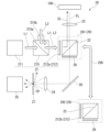
- FIG. FIG. 2 is a schematic diagram showing the configuration of the imaging section 20.
- FIG. 3 is a schematic diagram of the transport section 30 included in the detection device 1.
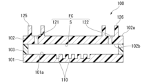
- FIG. 4 is a schematic perspective view showing the fluidic device 100.
- FIG. 5 is a cross-sectional view of fluidic device 100.
- FIG. 6 is a plan view showing a portion of the plurality of microwells 110.
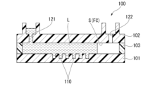
- FIG. 7 is an explanatory diagram of a method for detecting a sample using the fluidic device 100 described above.
- FIG. 8 is an explanatory diagram of a method for detecting a sample using the fluidic device 100 described above.
- FIG. 9 is an explanatory diagram of a method for detecting a sample using the fluidic device 100 described above.
- FIG. 10 is a schematic diagram illustrating an example of the ICA method.
- FIG. 11 is an explanatory diagram illustrating the operation of the detection device 1.
- FIG. 12 is an explanatory diagram illustrating the operation of the detection device 1.
- FIG. 13 is an explanatory diagram illustrating the operation of the detection device 1.
- FIG. 14 is an explanatory diagram illustrating the operation of the detection device 1.
- FIG. 15 is a schematic perspective view showing the detection device 2.
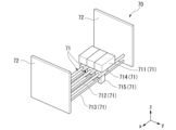
- FIG. 16 is a schematic perspective view of the moving means 70.
- FIG. 17 is a schematic perspective view showing the heating section 11 and the conveying section 35.
- FIG. 18 is an explanatory diagram illustrating the operation of the detection device 2.
- FIG. 19 is an explanatory diagram illustrating the operation of the detection device 2.
- the temperature adjustment section 10, the imaging section 20, the transport section 30, and the control section 40 are provided on a base 90.
- the detection device 1 is used to detect a target substance contained in a liquid sample. Specifically, the detection apparatus 1 is used to detect a target substance using the fluidic device 100 based on the principle of digital ICA (hereinafter referred to as dICA). The detection device 1 detects a target substance by exciting a product generated inside the fluidic device 100 with light and imaging and analyzing the generated fluorescence. Below, they will be explained in order.
- dICA digital ICA
- the temperature adjustment unit 10 includes a heating unit 11 that heats the fluid device 100 and a cooling unit 12 that cools the heated fluid device 100.
- the heating unit 11 in FIG. 1 generates heat on its upper surface (+z side surface) and directly heats the object in contact with the upper surface.
- the heating unit 11 can employ a heater using a known heating method, and examples thereof include resistance heating and induction heating.
- the heating unit 11 is shown as a rectangular member in plan view. It is preferable that the heating unit 11 is provided with a known temperature sensor such as a thermocouple so as to be able to control the temperature while measuring the temperature.
- a known temperature sensor such as a thermocouple
- the heating unit 11 has, for example, a lid having an internal space for accommodating a target object (that is, the fluid device 100), and indirectly heats the target object by heating the internal space. It is also possible to adopt a configuration in which the temperature is heated manually.
- the heating unit 11 is controlled by the control unit 40 to a temperature of 30°C or higher and 99°C or lower.
- the cooling unit 12 in FIG. 1 cools the object in contact with the upper surface.
- the cooling unit 12 may employ a known cooling method.
- the cooling unit 12 may employ a known Peltier element, and may have a configuration in which the upper surface is cooled by energization.
- the cooling unit 12 is shown as a rectangular member in plan view. It is preferable that the cooling unit 12 is provided with a known temperature sensor such as a thermocouple so as to be able to control the temperature while measuring the temperature.
- the cooling unit 12 is controlled by the control unit 40 to a temperature of 0.1°C or more and less than 30°C.
- the cooling unit 12 may be a heat transfer plate whose upper surface is made of metal with good heat transfer characteristics, and may have a configuration in which the lower surface has a known water-cooled or air-cooled heat dissipation section. Furthermore, the cooling unit 12 may be simply provided with a metal plate having good heat transfer characteristics.
- the temperature adjustment section 10 is provided on the mounting section 50 that spans above the base 90 (in the +z direction).
- the mounting unit 50 includes a stage 51 that is rectangular in plan view and extends in the x direction, and a pair of piers 52 provided at both ends of the stage 51 in the longitudinal direction.
- the temperature adjustment section 10 is arranged in order from one end 51a of the stage 51 in the +x direction, including the heating section 11 and the cooling section 12.
- a standby section 55 may be provided on the -x side of the heating section 11, where a transport stage (described later) of the transport section 30 waits.
- FIG. 2 is a schematic diagram showing the configuration of the imaging section 20.
- the imaging section 20 includes a light source section 21 , a dichroic mirror 22 , a projection lens 23 , an imaging lens 24 , an imaging means 25 , an absorption filter 26 , a spatial filter 27 , and a reflection mirror 28 .
- the light source 211 can be, for example, a known mercury lamp. Further, the light source 211 may be a known LED light source or LD light source. In the following description, it is assumed that the light source 211 is a mercury lamp that is a white light source, and that the light L1 is white light.
- the optical filter 212 transmits light (i.e., excitation light EL) of a wavelength necessary for excitation of a product (i.e., fluorescent substance) generated inside the fluidic device 100 out of the light L1 that is white light, and transmits the excitation light EL. Extract.
- the optical filter 212 is a bandpass filter that transmits the excitation light EL and blocks other light.
- the reflection mirror 215a of the external light introducing section 215 retreats from the optical path and allows the light L1 to pass. Furthermore, when using the external light L2, the reflection mirror 215a of the external light introduction section 215 is placed on the optical path to block the light L1 and direct the external light L2 introduced from the introduction port 215b toward the optical filter 212. lead to.
- the excitation light EL emitted from the light source section 21 enters the dichroic mirror 22.
- the dichroic mirror 22 has the property of reflecting the excitation light EL and transmitting the fluorescence FL.
- the dichroic mirror 22 is arranged at an angle of 45° (that is, an incident angle of 45°) with respect to the direction of incidence of the excitation light EL, and reflects the excitation light EL in a direction of 90° with respect to the direction of incidence of the excitation light EL. do.
- the excitation light EL reflected by the dichroic mirror 22 enters the projection lens 23 and is projected onto the fluidic device 100.
- fluorescence FL is emitted from the fluorescent substance excited by the excitation light EL.
- the fluorescent light FL enters the dichroic mirror 22 via the projection lens 23.
- the dichroic mirror 22 transmits the fluorescent light FL.
- the dichroic mirror 22 reflects the excitation light EL. Thereby, the excitation light EL and the fluorescence FL are separated.
- a dichroic mirror that transmits the fluorescent light FL and does not transmit light of other wavelengths can be used.
- a dichroic mirror which has a better wavelength separation ability than the dichroic mirror 22 and which transmits long wavelength light including the fluorescence FL and blocks (and reflects) short wavelength light including the excitation light EL. This eliminates stray light and enables highly accurate detection.
- the fluorescence FL that has passed through the absorption filter 26 enters the imaging lens 24 via the reflection mirror 28 and is imaged.
- the imaging means 25 captures an image formed by the imaging lens 24.
- a digital camera having a known imaging device can be employed.
- the projection lens 23 that projects the excitation light EL emitted from the light source unit 21 onto the fluidic device 100 collects the fluorescence FL generated from the fluidic device 100 and guides it to the imaging lens 24. It also serves as an objective lens.
- the projection lens 23 (and objective lens) may have an autofocus mechanism.
- the projection lens 23 and the imaging lens 24 preferably form a confocal optical system.
- the imaging unit 20 includes a spatial filter 27 having a pinhole P between the imaging lens 24 and the imaging means 25, and the confocal FP of the confocal optical system is provided between the imaging lens 24 and the imaging means 25. is located.
- the other confocal point of the confocal optical system is located at a position overlapping the fluidic device 100.
- the spatial filter 27 is arranged at a position where the pinhole P spatially overlaps with the confocal FP. This allows the imaging unit 20 to remove stray light and perform highly accurate detection. Note that in order to make the confocal optical system function, known members constituting the confocal optical system can be appropriately employed.
- the imaging unit 20 may include a filter block 29 in which an optical filter 212, a dichroic mirror 22, and an absorption filter 26 are integrated.
- the light source section 21 also includes a first optical filter 212a that transmits light of a first wavelength used as excitation light EL out of the light L1, and a second optical filter 212b that transmits light of a second wavelength used as excitation light EL.
- the first optical filter 212a and the second optical filter 212b may be configured to be switchable.
- the light source section 21 includes filter blocks 291 and 292 and a switching section 295.
- Filter block 291 has a first optical filter 212a.
- Filter block 292 has a second optical filter 212b.
- the switching unit 295 switches between the filter block 291 and the filter block 292.
- the switching unit 295 includes a turntable 296 and a drive unit 297.
- the turntable 296 is provided with a filter block, and the drive unit 297 drives the turntable 296 in the circumferential direction.
- the filter block 29 and the switching section 295 are supported by a support 299 provided on the base 90.
- the switching unit 295 can switch the filter block 292 provided on the turntable 296 by moving the turntable 296 in the circumferential direction using the drive unit 297.
- the transport section 30 includes a rail 31 extending in the x-axis direction, a transport main body 32 that moves in the ⁇ x-axis direction along the rail 31, and a drive section 33 that drives the transport main body 32.
- FIG. 3 is a schematic diagram of the transport section 30 included in the detection device 1.
- the transport main body 32 includes a first member 321, a second member 322, a stage 323, and a lighting section 325.
- the first member 321 is connected to the rail 31 and moves in the ⁇ x axis direction.
- the second member 322 is connected to the first member 321 and moves in the ⁇ z axis direction.
- Stage 323 connects to second member 322.
- the illumination unit 325 illuminates the stage 323.
- the stage 323 has an upper surface parallel to the xy plane, and the fluid device 100 to be observed is placed thereon.
- the stage 323 can have various configurations as long as the fluid device 100 is placed thereon and the fluid device 100 can be observed from below (ie, in the -z direction).
- the stage 323 may be a plate-like member having optical transparency, or may be a frame in which the observation portion of the fluidic device 100 is a gap.
- the stage 323 may be a gripping member that grips the fluid device 100 from the side. In FIG. 3, three fluid devices 100 are placed, but the number of fluid devices 100 placed on the stage 323 can be set depending on the size of the stage 323.
- the illumination unit 325 illuminates the fluidic device 100 placed on the stage 323 with white light, thereby enabling bright field imaging.
- Such a transport unit 30 can move the fluid device 100 placed on the stage 323 in the x-axis direction and the z-axis direction.
- Control unit The control unit 40 shown in FIG. 1 controls the operations of the temperature adjustment unit 10, the imaging unit 20, and the transport unit 30.
- the control unit 40 may be a dedicated device provided in the detection device 1, or may be a general-purpose computer installed with control software.
- FIG. 4 is a schematic perspective view showing the fluidic device 100.
- FIG. 5 is a cross-sectional view of the fluidic device 100, taken along line VV in FIG. 4. As shown in FIG. The fluidic device 100 is used to detect a target substance contained in a liquid sample (liquid sample).
- a liquid sample is an aqueous solution containing a target substance, and includes, for example, a biological sample or an environmental sample.
- Biological samples are not particularly limited, and include serum, plasma, urine, cell culture fluid, and the like. Alternatively, it may be a PCR reaction solution or the like that uses a biological sample as a template and contains a staining reagent as a detection reagent.
- examples of environmental samples include river water and industrial wastewater.
- target substances include DNA, RNA, proteins, viruses, cells, and exosomes.
- examples of RNA include miRNA and mRNA.
- examples of cells include bacteria, yeast, animal cells, plant cells, and insect cells.
- the target substance contained in the sample as described above is reacted with a detection reagent to detect the target substance.
- the fluidic device 100 includes a well plate 101, a lid member 102, and a wall member 103.
- the fluidic device 100 is used as a reaction vessel that accommodates a sample in an internal space S and performs a reaction to detect a target substance contained in the sample.
- the well plate 101 is a plate-like member that is rectangular or strip-shaped in plan view.
- a plurality of wells (also referred to as microwells) 110 are provided on the upper surface 101a of the well plate 101 at the center in the longitudinal direction of the well plate 101.
- the microwell 110 is a recess provided in the upper surface 101a of the well plate 101, and is open to the upper surface 101a.
- the microwell 110 refers to a space surrounded by the recess and a virtual plane parallel to and in contact with the upper surface 101a.
- the microwell 110 accommodates the sample contained in the internal space S, and functions as a reaction field between the target substance contained in the sample and the detection reagent.
- the material of the well plate 101 has electromagnetic wave transparency.
- electromagnetic waves to be evaluated for transparency include X-rays, ultraviolet rays, visible light, and infrared rays.
- electromagnetic wave transparency it becomes possible to utilize electromagnetic waves in order to analyze the results of experiments conducted with the fluidic device 100 having the well plate 101. For example, fluorescence or phosphorescence generated as a result of irradiation with electromagnetic waves can be measured from the well plate 101 side.
- the microwell 110 when detecting a sample by generating fluorescence having a peak in the wavelength range of 400 to 700 nm, which is the visible light region, in the microwell 110, the microwell 110 is good for at least light in the visible light region.
- a material with good transparency may be used.
- Examples of materials having electromagnetic wave permeability include glass and resin.
- the resin include ABS resin, polycarbonate, COC (cycloolefin copolymer), COP (cycloolefin polymer), acrylic resin, polyvinyl chloride, polystyrene, polyethylene, polypropylene, polyvinyl acetate, PET (polyethylene terephthalate), and PEN ( polyethylene naphthalate), etc.
- These resins may contain various additives, or may be a polymer alloy in which a plurality of resins are mixed.
- the material having electromagnetic wave transparency has substantially no autofluorescence.
- substantially no autofluorescence means that the material has no autofluorescence at the wavelength used for sample detection, or it is so weak that it does not affect sample detection.
- the autofluorescence is 1/2 or less, more preferably 1/10 or less of the fluorescence of the detection target, it can be said to be so weak that it does not affect sample detection.
- detection sensitivity can be increased in sample detection using electromagnetic waves.
- the thickness of the well plate 101 can be determined as appropriate. When observing fluorescence using a fluorescence microscope from the well plate 101 side, the thickness of the well plate 101 may be, for example, 5 mm or less, 2 mm or less, or 1.6 mm or less. good.
- the well plate 101 may have a single layer structure using only the above-mentioned materials, or may be a laminate of a plurality of materials.
- the layer having the microwells 110 and the layer supporting the layer may be made of different materials.
- microwell 110 Various shapes can be adopted as the shape of the microwell 110.
- the shape of the microwell 110 include a cylindrical shape such as a cylinder, an elliptical cylinder, and a polygonal cylinder, a conical shape such as a cone and a pyramid, and a truncated cone shape such as a truncated cone and a truncated pyramid.
- the opening diameter gradually decreases in the depth direction of the well.
- the maximum diameter of the microwell 110 in plan view is, for example, preferably 10 nm to 100 ⁇ m, more preferably 100 nm to 50 ⁇ m, and even more preferably 1 ⁇ m to 20 ⁇ m.
- the depth of the microwell 110 is preferably, for example, 10 nm to 100 ⁇ m, more preferably 100 nm to 50 ⁇ m, and even more preferably 1 ⁇ m to 20 ⁇ m.
- the capacity of the microwell 110 is, for example, preferably 1 fL to 6 nL, more preferably 1 fL to 5 pL, even more preferably 1 fL to 2 pL, and particularly preferably 1 fL to 300 fL.
- enzyme reactions such as digital PCR and invader reactions can be suitably performed in a microscopic space.
- gene mutation detection can be performed by digital PCR.
- the well plate 101 has a plurality of microwells 110 of the same shape and size.
- the same shape and same size may be defined as having the same shape and the same capacity to the extent required for digital measurement, and variations to the extent of manufacturing errors are acceptable.
- the density of the microwells 110 is, for example, 100,000 to 10 million cells/cm 2 , preferably 100,000 to 5 million cells/cm 2 , and more preferably 100,000 to 1 million cells/cm 2 .
- the density of the microwells 110 is within this range, it is easy to encapsulate a sample in a predetermined number of microwells 110. Furthermore, observation of wells for analyzing experimental results is easy.
- the abundance ratio of the mutation to be detected relative to the wild type is about 0.01%, for example, 1 to 2 million microwells are used. 110 is preferably used.
- FIG. 6 is a plan view showing a portion of the plurality of microwells 110. As shown in FIG. 6, the plurality of microwells 110 in the well plate 101 have the same shape in plan view. Note that a small number (for example, 1 to 4) of the plurality of microwells may have different shapes in order to be used as an alignment mark in imaging or device manufacturing.
- the plurality of microwells 110 are regularly arranged in a matrix.
- the expression that the microwells 110 are "regularly arranged” means that the centers of gravity of the openings of the plurality of microwells 110 are arranged in a fixed pattern.
- the centers of gravity of the openings of the microwells 110 may be arranged in a square grid.
- a line connecting the centers of gravity of the openings of four adjacent microwells 110 forms a rectangle, preferably a square.
- the centers of gravity of the openings of the microwells 110 may be arranged in a triangular lattice shape (hexagonal lattice shape). In this case, lines connecting the centers of gravity of the openings of three adjacent microwells 110 form an equilateral triangle.
- an arbitrary well (first well) A and a well (second well) B closest to well A preferably satisfy the following formula (1).
- 0.8 ⁇ Da/Dab ⁇ 1 (1) (Da is the equivalent circle diameter of the opening of well A, and Dab is the distance between the center of gravity of the opening of well A and the center of gravity of the opening of well B.)
- the lower limit of the value of Da/Dab is 0.8, and may be 0.83 or more. Further, the upper limit of the value of Da/Dab is less than 1, may be 0.92 or less, or may be about 0.9. These lower limit values and upper limit values can be arbitrarily combined.
- the microwells 110 shown in FIG. 6 are arranged in a triangular lattice. As shown in FIG. 6, the centers of gravity Ca, Cb, and Cc of the respective openings of any well A, well B closest to well A, and well C closest to both well A and well B form an equilateral triangle with each as a vertex.
- the equivalent circular diameter of the opening of the microwell 110 is preferably 1 ⁇ m or more and 50 ⁇ m or less. That is, the lower limit of the equivalent circular diameter of the opening of the microwell 110 is preferably 1 ⁇ m.
- the upper limit of the equivalent circle diameter of the opening of the microwell 110 may be less than 20 ⁇ m, may be less than 19 ⁇ m, may be less than 18 ⁇ m, may be less than 17 ⁇ m, and may be less than 16 ⁇ m. It may be 15 ⁇ m or less, 14 ⁇ m or less, 13 ⁇ m or less, 12 ⁇ m or less, 11 ⁇ m or less, 10 ⁇ m or less. It's okay.
- the upper limit and lower limit of the equivalent circle diameter of the opening of the microwell 110 can be arbitrarily combined.
- the lid member 102 has the same contour shape as the well plate 101 (that is, a rectangular shape) in plan view.
- the lid member 102 is arranged to face the upper surface 101a of the well plate 101 with a gap therebetween.
- the lid member 102 has two through holes that penetrate in the thickness direction.
- the two through holes are provided at one end and the other end of the lid member 102 in the longitudinal direction, respectively.
- One of the through holes is an inlet 121 used when injecting a liquid substance into the internal space S of the fluid device 100, and the other through hole is an outlet 122 used when discharging a liquid substance from the internal space S. be.
- liquid material includes not only liquid samples but also detection reagents and sealing liquids.
- the inlet 121, the internal space S, and the outlet 122 communicate in this order, forming a flow path FC as a whole.
- a detection reaction of a target substance is performed by appropriately flowing a liquid material through the channel FC.
- a plurality of microwells 110 are arranged between an inlet 121 and an outlet 122.
- a cylindrical injection port 125 surrounding the injection port 121 is provided on the upper surface 102a of the lid member 102. Injection port 125 communicates with inlet 121 .
- the injection port 125 is used, for example, to connect a syringe when filling the internal space with a liquid substance using a syringe filled with a liquid substance.
- a cylindrical discharge port 126 surrounding the discharge port 122 is provided on the upper surface 102a of the lid member 102.
- Exhaust port 126 communicates with exhaust port 122 .
- the discharge port 126 is used, for example, to connect a tube through which the liquid flows when extracting the liquid from the internal space S.
- the material of the lid member 102 As the material of the lid member 102, the material exemplified as the material of the well plate 101 mentioned above can be adopted.
- the material of the lid member 102 may be the same as the material of the well plate 101, or may be different.
- the material of the lid member 102 is preferably hydrophobic. Specifically, it is preferable that the material forming the surface of the lid member 102 facing the internal space S (that is, the lower surface 102b) has a contact angle with the sealing liquid SL of 5° or more and 80° or less. When the lid member 102 is formed of such a material, the contact angle between the lower surface 102b and the sealing liquid SL will be 5° or more and 80° or less. When the contact angle of the lower surface 102b is within the above range, the sample tends to be easily isolated in the microwell 110 when a sealing liquid is introduced into the internal space S by the method described later.
- the wall member 103 is formed into a closed ring shape when viewed from above, and is arranged along the outer edge of the upper surface 101a of the well plate 101.
- the wall surface of the wall member 103 facing the internal space S is approximately rectangular in plan view, and the width gradually decreases on the injection port 121 side.
- the wall member 103 is sandwiched between the well plate 101 and the lid member 102, and together form the fluid device 100.
- a space surrounded by the well plate 101, the lid member 102, and the wall member 103 is an internal space S in which a liquid sample is accommodated.
- the internal space S extends in the longitudinal direction of the well plate 101 along the rectangular well plate 101.
- the wall member 103 not only functions as a wall surface of the internal space S, but also functions as a spacer between the well plate 101 and the lid member 102.
- the height of the wall member 103 that is, the height of the internal space S, may be, for example, 100 ⁇ m or less.
- the material of the wall member 103 is not particularly limited, but for example, a double-sided adhesive tape in which an acrylic adhesive is laminated on both sides of a core film can be suitably used.
- Examples of materials for the core film include silicone rubber and acrylic foam.
- the same material as the well plate 101 described above can be used for the wall member 103.
- the wall member 103 made of such a material can be integrated with the well plate 101 and the lid member 102 by adhesive bonding, thermal welding, ultrasonic welding, laser welding, or the like.
- the wall member 103 may be formed integrally with the well plate 101 and constitute a part of the well plate 101. Similarly, the wall member 103 may be formed integrally with the lid member 102 and constitute a part of the lid member 102.
- the well plate 101 described above can be manufactured using known injection molding, microimprinting technology, or nanoimprinting technology. Further, the well plate 101 can also be manufactured by forming the microwells 110 by etching using a known photolithography technique.
- the above-mentioned lid member 102 and wall member 103 can be manufactured by known injection molding.
- the detection reagent is used to detect the target substance by reacting with the target substance.
- Detection reagents include buffer substances, enzymes, substrates, antibodies, antibody fragments, and the like.
- the enzyme is selected in accordance with the content of the biochemical reaction in order to perform a biochemical reaction such as an enzymatic reaction on a template nucleic acid related to the target substance.
- a biochemical reaction to a template nucleic acid is, for example, a reaction in which signal amplification occurs under conditions in which the template nucleic acid is present.
- the detection reagent is selected depending on the detection reaction employed. Specific detection reactions include the ICA method, the loop-mediated isothermal amplification (LAMP) method (registered trademark), the 5' ⁇ 3' nuclease method (TaqMan (registered trademark) method), the fluorescent probe method, and the like.
- 7 to 9 are explanatory diagrams of a method for detecting a sample using the above-described fluidic device 100.
- a liquid sample and a detection reagent are mixed to prepare a mixed aqueous solution.
- concentration of the detection reagent in the mixed aqueous solution is adjusted as appropriate depending on the type of detection reagent used and the type of detection reaction.
- the detection reagent used may contain an adsorption inhibitor.
- Anti-adsorption agents include surfactants and proteins.
- the sample may be pretreated prior to preparing the mixed aqueous solution.
- Pretreatment includes concentration adjustment (that is, dilution or concentration), support on a carrier, and binding reaction of two or more target substances.
- a mixed aqueous solution L containing a detection reagent is injected into the internal space S from the injection port 121.
- the mixed aqueous solution L flows through the internal space S (that is, the flow path FC)
- the microwell 110 that is open to the internal space S is also filled with the mixed aqueous solution L.
- the mixed aqueous solution L that has passed through the flow path FC is discharged from the discharge port 122.
- the concentration of the mixed aqueous solution L in advance so that one target substance is filled inside one microwell 110.
- concentration of the mixed aqueous solution L in advance so that one target substance is filled inside one microwell 110.
- one microwell 110 is filled with one or less target substances, that is, zero or one target substance.
- the number of microwells 110 in which a detection reaction, which will be described later, has been confirmed corresponds to the number of target substances, and the target substances can be detected one by one, that is, digital measurement becomes possible. Note that the target substance does not need to be introduced into all microwells 110.
- the means for introducing the target substance into the microwell 110 is not particularly limited, and an appropriate means can be selected depending on the target substance to be detected. For example, there is a method in which the target substance is allowed to settle within the fluidic device 100 (specifically, within the channel FC) by its own weight, and then distributed to the microwells.
- a substance that captures the target substance may be used to bind the capture substance to the target substance, which does not easily settle under its own weight, and then send the liquid.
- the efficiency of introduction of the target substance into the microwell 110 can be improved by immobilizing the capture substance in the microwell in advance and allowing the capture substance to capture the target substance sent together with the mixed aqueous solution L. .
- the reaction that binds the captured material and the target substance can be performed at any time.
- the target substance and the captured substance may be brought into contact in a sample tube.
- the target substance may be introduced into the microwell 110, and the captured substance and the target substance may be brought into contact with each other in the microwell 110.
- a capture substance is a substance that can capture a target substance.
- the capture material may be, for example, a combination of a solid phase and a substance that specifically binds to the target substance.
- Examples of the solid phase constituting the supplement include particles, membranes, and substrates. Furthermore, the number of substances that specifically bind to the target substance may be one type, or two or more types may be used. For example, there may be three types, four types, or five or more types.
- the particles are not particularly limited, and include polymer particles, magnetic particles, glass particles, and the like.
- the particles are surface-treated to avoid non-specific adsorption.
- particles having a functional group such as a carboxyl group on the surface are preferable. More specifically, a product such as "Magnosphere LC300" manufactured by JSR Corporation can be used.
- cells to which the virus can attach ie, cells that have virus receptors
- the capture material may be used as the capture material.
- the sealing liquid SL is sent from the injection port 121 to the flow path FC.
- the sealing liquid SL sent to the channel FC flows in the surface direction of the upper surface 101a in the internal space S, and out of the mixed aqueous solution L sent to the channel FC, the mixed solution SL that is not accommodated in the microwell 110 is removed. Aqueous solution L is flushed away and replaced.
- FIG. 9 shows a state in which all of the plurality of microwells 110 are sealed with the sealing liquid SL, and all the channels FC are replaced with the sealing liquid SL.
- the fluidic device 100 is heated to cause a reaction between the target substance and the detection reagent.
- a method for detecting the target substance any known detection method can be used depending on the characteristics of the target substance to be detected. This can be carried out by first performing a reaction (also referred to as signal amplification reaction) in which a signal derived from the target substance is amplified to a detectable level, and then detecting the amplified signal using an appropriate means.
- an isothermal signal amplification reaction can be adopted as the signal amplification reaction, and ICA reaction, loop-mediated isothermal amplification (LAMP) method (registered trademark), 5' ⁇ 3' nuclease method (TaqMan (registered trademark)), etc. (Trademark) method) or a fluorescent probe method can be employed.
- LAMP loop-mediated isothermal amplification
- TaqMan registered trademark
- Trademark fluorescent probe method
- signal amplification progresses through a cycle of two reactions: (1) complementary binding between nucleic acids, and (2) recognition and cleavage of a triplex structure by an enzyme.
- the influence of reaction cycle inhibition by impurities other than the target substance is small. Therefore, even if various components other than the target substance (for example, impurities) are present in the microwell 110, the target substance can be detected with high accuracy by using the ICA reaction.
- the mixed aqueous solution L contains reaction reagents and template nucleic acids necessary for the ICA reaction.
- the fluorescent substance is released from the quencher by an isothermal enzymatic reaction, and a predetermined fluorescent signal is emitted in response to the excitation light.
- the reaction temperature between the target substance and the detection reagent is preferably 50°C or higher and 99°C or lower.
- the specific reaction temperature may be determined through preliminary experiments depending on the reagents used and the sensitivity of the desired results. After determining the composition of the reagents to be used, conduct an ICA reaction as a preliminary experiment, and determine the reaction temperature based on the results of the signal, noise, signal-to-noise ratio (also called S/N ratio), and signal-to-noise difference after a certain period of time. Better to optimize.
- FIG. 10 is a schematic diagram illustrating an example of the ICA method.
- FIG. 10 shows how DNA, which is a target substance, is detected by the ICA method.
- the flap probe 810 and the invasion probe 830 are nucleic acid fragments (also referred to as oligonucleotides) designed to hybridize to DNA as a target substance (also referred to as target DNA) and form a flap structure with the double-stranded nucleic acid 140. It is.
- the fluorescent substrate 820 has a hairpin structure and is a nucleic acid fragment in which a fluorescent substance F and a quencher Q are bound.
- a fluorescent substance F is bound to the 5' end of the nucleic acid fragment, and a quencher Q is bound to a few bases 3' from the 5' end.
- the quencher Q suppresses the luminescence of the fluorescent material F.
- the flap probe 810 and the invasion probe 830 are hybridized to the target DNA.
- the flap probe 810 and the invasion probe 830 each overlap by one base at the SNP site of the target DNA, forming an unstable three-base-like structure.
- a first flap portion 811 is formed.
- the first flap region 811 is a portion of the flap probe 810 that did not hybridize with the target DNA.
- the generated nucleic acid fragment 811 hybridizes to the fluorescent substrate 820.
- Nucleic acid fragment 811 invades the hairpin structure of fluorescent substrate 820, overlaps by one base at the SNP site, and forms an unstable three-base-like structure.
- a second flap portion 821 is formed.
- the second flap region 821 is a portion of the fluorescent substrate 820 that is no longer hybridized due to the invasion of the nucleic acid fragment 811.
- the fluorescent substance F separates from the quencher Q and generates fluorescence FL.
- Target DNA can be detected by detecting this fluorescence FL.
- Detection of the target substance can also be performed by binding a substance that specifically binds to the target substance (also referred to as a specific binding substance) to the target substance, and detecting the bound specific binding substance.
- a substance that specifically binds to the target substance also referred to as a specific binding substance
- the target substance is a protein
- it can be detected using ELISA. More specifically, detection may be performed by sandwich ELISA using, for example, the principle of FRET.
- the target substance eg, antigen
- the target substance eg, antigen
- the target substance is brought into contact with both the first specific binding substance and the second specific binding substance to form a complex.
- the distance between the donor and acceptor becomes close, and the fluorescence wavelength of the acceptor can be detected by irradiation with the excitation wavelength of the donor.
- the specific binding substance may be labeled with a nucleic acid fragment, and the nucleic acid fragment may be detected by an ICA reaction.
- the specific binding substance substances similar to specific binding molecules for the structure described below, such as antibodies, antibody fragments, or aptamers, can be used.
- the specific binding substance may be labeled directly or indirectly, for example with an enzyme such as horseradish peroxidase (HRP).
- HRP horseradish peroxidase
- a mixed aqueous solution of a liquid sample containing a target substance and a detection reagent that reacts with the target substance to produce a product that emits fluorescence is housed in the fluidic device 100, and the stage of the transport body 32 is Place it on 323. This operation is preferably performed in the standby section 55 of the fluid device 100.
- the control unit 40 preferably heats the heating unit 11 in advance (also referred to as preheating) to a temperature higher than room temperature and lower than a preset reaction temperature.
- the reaction temperature between the target substance and the detection reagent is preferably 50°C or more and 99°C or less.
- the preheating temperature is preferably higher than room temperature, for example, 90° C. or lower. "Room temperature” is, for example, 25°C.
- the transport section 30 is driven to move the fluid device 100 placed on the stage 323 to the heating section 11. Thereby, the fluid device 100 is heated in the heating section 11 .
- the control section 40 changes the heating temperature of the heating section 11 from the preheating set temperature. , it is preferable to change the reaction temperature to that of the ICA reaction.
- the control unit 40 changes the heating temperature of the heating unit 11 from the preheating set temperature to the reaction temperature of the ICA reaction at some point while the transport unit 30 transports the fluid device 100 from the standby unit 55 to the heating unit 11. It is recommended to change it to .
- control unit 40 cools (preliminarily cools) the cooling unit 12 to a preset cooling temperature or higher and lower than the reaction temperature in the heating unit 11 in advance.
- the precooling temperature is preferably, for example, 0°C or higher and lower than room temperature.
- the transport section 30 is driven to move the fluid device 100 placed on the stage 323 from the heating section 11 to the cooling section 12. Thereby, the fluid device 100 is cooled in the cooling section 12 .
- the control unit 40 changes the cooling temperature of the cooling unit 12 from the pre-cooling set temperature. , it is better to change it to the actual cooling temperature.
- the control unit 40 changes the cooling temperature of the cooling unit 12 from the pre-cooling set temperature to the actual cooling temperature at some point while the transport unit 30 transports the fluid device 100 from the heating unit 11 to the cooling unit 12. It is a good idea to change it.
- the transport unit 30 is driven to move the fluid device 100 placed on the stage 323 from the cooling unit 12 to above the projection lens 23 of the imaging unit 20.
- the imaging unit 20 irradiates the fluidic device 100 with excitation light and captures an image of the generated fluorescence.
- the number of wells emitting fluorescence can be counted and the target substance can be quantified.
- the detection device 1 as described above provides the following effects.
- the detection reagent When the detection reagent continues to be heated, it produces a product that emits fluorescence due to a side reaction even in the absence of the target substance.
- the product generated in this way cannot be distinguished from the fluorescence caused by the target substance in the image captured by the imaging unit 20, and may cause an error in detection of the target substance.
- the ICA reaction progresses between heating and cooling. Therefore, if it takes time from heating to cooling, both the signal emission to be detected and the noise emission will become stronger, and it is assumed that the detection sensitivity will decrease.
- the detection device 1 after heating in the heating unit 11, the fluid device 100 is cooled in the cooling unit 12 provided separately from the heating unit 11. Therefore, the reaction between the target substance and the detection reagent, which had been accelerated by heating, can be deactivated and side reactions can be suppressed. These allow the detection device 1 to perform highly accurate detection.
- a cooling unit is also provided at the location where the heating unit 11 is provided, and the configuration is such that both heating and cooling can be performed at the same location, when cooling is started after heating, the ICA reaction etc.
- the heating section 11 that has been heated to the reaction temperature in the detection reaction also needs to be cooled down. In such a configuration, although it is possible to cool the fluid device 100, additional time is required to cool the heating section 11.
- the fluid device 100 is made of glass or resin. Further, liquid such as a liquid sample or a reagent is stored inside the fluidic device 100. Furthermore, in order to increase the volume of the fluidic device 100, changes such as attaching a separate member to the device or enlarging the device itself are envisaged. All of these increase the specific heat of the fluid device 100 and inhibit quick cooling of the fluid device 100.
- the detection device 1 since the heating section 11 and the cooling section 12 are provided separately, compared to the device configuration in which the cooling section is also provided at the location where the heating section 11 is provided, , the fluidic device 100 can be quickly cooled. Furthermore, in the detection device 1, since the heating section 11 and the cooling section 12 are provided separately, the above-mentioned preheating and precooling are possible. Thereby, the detection device 1 can perform detection in a short time, improving work efficiency.
- the detection device 1 having the above configuration, it is possible to provide a detection device that can perform a large number of detections in a short time while ensuring high detection accuracy in detection based on digital ICA.
- a member for cooling the object is provided at the position of the cooling unit 12, but the present invention is not limited to this.
- the cooling device may have any configuration as long as the fluid device 100 heated by the heating unit 11 is transported to the imaging position of the imaging unit 20 and cooling of the fluid device 100 is completed before observation is started.
- the fluid device 100 may be cooled by blowing air while the fluid device 100 is being transported from the heating unit 11 to the imaging position.
- the means for blowing air along the conveyance path from the heating section 11 to the imaging position corresponds to the cooling section.
- the fluid device 100 may be cooled at the imaging position.
- the means for cooling the fluid device 100 can employ a known configuration.
- means for cooling the fluid device 100 at the imaging position corresponds to the cooling unit.
- observation (or imaging) may be performed while cooling, or observation (or imaging) may be performed after cooling.
- the control unit 40 controls the autofocus mechanism prior to imaging to adjust the focal position of the objective lens to the microwell 110. You can do that.
- the detection device 1 can capture an image with high accuracy and perform highly accurate detection.
- the microwell 110 as an alignment mark and adjusting the focus position to the microwell 110 in advance, the focus position can be quickly readjusted even if the entire fluidic device 100 is warped or distorted. be able to.
- the focal position of the objective lens may be adjusted to the microwell 110 using another method.
- an alignment mark may be provided on the fluidic device 100, and the detection device 1 may image another microwell 110 after focusing using the alignment mark.
- the alignment mark is preferably provided at the same focal position as the microwell 110.
- the focal position of the alignment mark is different from the focal position of the microwell 110 in the z-axis direction, the amount of deviation between the two focal positions is measured, the amount of deviation is corrected, and the focal position is adjusted to the microwell 110. may be imaged.
- the focal length for each microwell 110 may be different for each microwell 110.
- the focal lengths of the microwells 110 located at the periphery of the array and the center of the array were measured, and the obtained focal length and focal length were measured.
- the amount of warpage of the fluidic device 100 may be roughly estimated from the correspondence with the position of the microwell 110. It is preferable to image the microwell 110 by using the obtained amount of warpage as a correction value for the amount of deviation and aligning the focal position.
- the amount of warpage of the fluidic device 100 is estimated from the focal length of the microwell 110, but an alignment mark that the fluidic device 100 has may be used as a measurement target when calculating the amount of warpage.
- the alignment mark provided on the fluidic device 100 may be provided using a part of the plurality of wells (for example, 1 to 4) as described above, or may be provided separately around the area where the microwell 110 is provided. good.
- a composite image in which the entire image is in focus may be obtained by capturing images of the fluidic device 100 at a plurality of focal positions and synthesizing a known z-stack image using the plurality of obtained images.
- FIG. 15 to 19 are explanatory diagrams of a detection device according to a second embodiment of the present invention. Components in this embodiment that are common to those in the first embodiment are given the same reference numerals, and detailed explanations will be omitted.
- FIG. 15 is a schematic perspective view showing the detection device 2 of this embodiment, and corresponds to FIG. 1 of the first embodiment.
- the detection device 2 includes a temperature adjustment section 10, an imaging section 20, a transport section 35, and a control section 40. Furthermore, the detection device 2 includes a lid 60 and a moving means 70.
- the lid 60 is a box-shaped member that covers the entire structure arranged on the stage 51.
- the lid 60 is provided so that it can be opened and closed by rotating around a rotation axis that passes through a point P1 and is set parallel to the x-axis.
- FIG. 16 is a schematic perspective view of the moving means 70.
- the moving means 70 is provided on the inner upper surface of the lid 60 (see FIG. 15).
- the moving means 70 has a plurality of (three in the figure) extrusion parts 71 arranged in the y direction, and a pair of attachment parts 72 that support the extrusion parts 71 on both sides in the x direction.
- the attachment portion 72 is shown as a plate-shaped member that collectively supports the plurality of extrusion portions 71, but there is no particular limitation.
- the extrusion section 71 has a motor 711, a feed screw 712, a guide shaft 713, a nut 714, and a hook 715.
- the motor 711 rotates the feed screw 712 via a reduction gear (not shown).
- the feed screw 712 is provided extending in the x direction. Both ends of the feed screw 712 in the x direction are rotatably supported by the mounting portion 72 . The feed screw 712 is rotated around the central axis of the feed screw 712 by being driven by the motor 711 .
- the guide shaft 713 is provided extending in the x direction at the position of the feed screw 712 in the -z direction.
- the guide shaft 713 is inserted into a through hole (not shown) provided in the hook 715, and both ends in the x direction are fixed at the attachment part 72.
- a feed screw 712 is inserted into the nut 714.
- a hook 715 is coupled to the lower side (-z side) of the nut 714.
- the shape of the hook 715 is not particularly limited as long as it has the extrusion function described below.
- FIG. 17 is a schematic perspective view showing the heating section 11 and the conveying section 35.
- the heating section 11 has a temperature control holder 15 .
- the temperature control holder 15 may be integrally formed on the upper surface of the heating section 11, or may be formed as a separate member from the heating section 11 and fixed to the upper surface of the heating section 11.
- the temperature control holder 15 has a base 151 that is rectangular in plan view, and a plurality of (four in the figure) rails 152 extending in the x direction on the upper surface of the base 151.
- the interval between adjacent rails 152 is equivalent to the width of the fluid device 100 in the transverse direction, and a groove (also referred to as a first accommodating portion) 152a into which the fluid device 100 is inserted is formed between the rails 152.
- the groove 152a is formed to extend in the transport direction of the transport main body 36, that is, in the x direction.
- At least the base part 151 is formed of a metal material with high thermal conductivity such as aluminum or copper.
- the transport section 35 has a transport main body 36.
- the transport main body 36 includes a first member 321, a second member 322, and a measurement holder 330.
- the measurement holder 330 includes a base 331 that is rectangular in plan view, a plurality of (four in the figure) rails 332 extending in the x direction on the upper surface of the base 331, and a wall 333 provided at the +x side end of the rails 332. , has.
- the base 331 can have various configurations as long as the fluid device 100 is placed thereon and the fluid device 100 can be observed from below (that is, in the -z direction).
- the stage 323 may be a plate-like member having optical transparency, or may be a frame in which the observation portion of the fluidic device 100 is a gap.
- the top surface of the base 331 of the measurement holder 330 and the top surface of the base 151 of the temperature control holder 15 are approximately at the same height in the z direction.
- the interval between adjacent rails 332 is equivalent to the width of the fluid device 100 in the transverse direction, and a groove (second accommodating portion) 332a into which the fluid device 100 is inserted is formed between the rails 332.
- the groove 332a is formed to extend in the transport direction of the transport main body 36, that is, in the x direction. Further, the +x side of the groove 332a is closed by a wall portion 333.
- grooves 152a of the temperature control holder 15 and the grooves 332a of the measurement holder 330 shown in FIG. 17 are the same, they may be different.
- the grooves 152a and the grooves 332a are each arranged in the x direction.
- grooves 152a of the temperature control holder 15 and the extrusion portions 71 of the moving means 70 shown in FIG. 16 are, for example, the same number, but may be different.
- FIGS. 18 and 19 are explanatory diagrams illustrating the operation of the detection device 2.
- illustration of the guide shaft of the extrusion portion 71 is omitted for ease of viewing.
- the detection device 2 can observe heating and cooling of each of the plurality of fluid devices 100 at different times.
- the fluid device 100 is placed in the groove 152a (see FIG. 17) of the temperature control holder 15, and the fluid device 100 and the temperature control holder 15 are heated in the heating section 11.
- the transport main body 36 is moved in the ⁇ x direction to bring the end of the measurement holder 330 on the ⁇ x side and the end of the temperature control holder 15 on the +x side close to each other.
- the lower end of the hook 715 of the extrusion part 71 is located on the ⁇ z side with respect to the upper surface of the fluid device 100.
- the motor 711 of the extrusion section 71 is driven to move the nut 714 and hook 715 in the +x direction.
- the hook 715 contacts the fluid device 100A when moving in the +x direction, and as the hook 715 moves, the fluid device 100A is pushed out in the +x direction and moved to the measurement holder 330.
- the fluidic device 100 transferred to the measurement holder 330 is accommodated in the groove 332a.
- the remaining fluid devices 100B remain placed in the temperature control holder 15.
- the transport unit 35 moves the transport main body 36 in the +x direction.
- the detection device 2 appropriately cools the fluid device 100A in the cooling section 12 (see FIG. 15), and performs imaging and detection using the imaging section 20.
- the detection device 2 performs the same operation as the fluid device 100A for the remaining fluid device 100B, and performs imaging and detection using the imaging unit 20 (see FIG. 15).
- the detection process can be performed with different heating times between the fluid device 100A and the fluid device 100B.
- the detection device 2 configured as described above, it is possible to provide a detection device that can perform a large number of detections in a short time while ensuring high detection accuracy in detection based on digital ICA.
Landscapes
- Health & Medical Sciences (AREA)
- Chemical & Material Sciences (AREA)
- Immunology (AREA)
- Physics & Mathematics (AREA)
- Biochemistry (AREA)
- General Health & Medical Sciences (AREA)
- Life Sciences & Earth Sciences (AREA)
- Pathology (AREA)
- Analytical Chemistry (AREA)
- General Physics & Mathematics (AREA)
- Nuclear Medicine, Radiotherapy & Molecular Imaging (AREA)
- Chemical Kinetics & Catalysis (AREA)
- Optics & Photonics (AREA)
- Molecular Biology (AREA)
- Clinical Laboratory Science (AREA)
- Investigating, Analyzing Materials By Fluorescence Or Luminescence (AREA)
- Automatic Analysis And Handling Materials Therefor (AREA)
- Apparatus Associated With Microorganisms And Enzymes (AREA)
- Optical Measuring Cells (AREA)
- Measuring Or Testing Involving Enzymes Or Micro-Organisms (AREA)
- Investigating Or Analysing Materials By The Use Of Chemical Reactions (AREA)
Abstract
Description
本願は、2022年7月1日に日本に出願された特願2022-106963号について優先権を主張し、その内容をここに援用する。
以下、図1~図14を参照しながら、本発明の第1実施形態に係る検出装置及び流体デバイスについて説明する。なお、以下の全ての図面においては、図面を見やすくするため、各構成要素の寸法や比率などは、適宜異ならせてある。
図1は、本実施形態の検出装置1を示す概略斜視図である。検出装置1は、温度調整部10と、撮像部20と、搬送部30とを有する。さらに、検出装置1は、検出装置1の動作を制御する制御部40を有する。
以下、順に説明する。
温度調整部10は、流体デバイス100の加熱を行う加熱部11と、加熱された流体デバイス100を冷却する冷却部12と、を有する。
撮像部20は、ステージ51において冷却部12よりも+x側に設けられている。撮像部20は、流体デバイス100に励起光を照射するとともに、流体デバイス100から発せられる蛍光の像を撮像する。
図1に示すように、搬送部30は、x軸方向に延びるレール31と、レール31に沿って±x軸方向に移動する搬送本体32と、搬送本体32を駆動する駆動部33と、を有する。
図1に示す制御部40は、温度調整部10、撮像部20及び搬送部30の動作を制御する。制御部40は、検出装置1に設けられた専用の装置であってもよく、制御用のソフトウエアをインストールした汎用のコンピュータを用いてもよい。
図4及び図5に示すように、流体デバイス100は、ウェルプレート101、蓋部材102及び壁部材103を有する。流体デバイス100は、内部空間Sに試料を収容し、試料に含まれる標的物質の検出反応を行う反応容器として用いられる。
ウェルプレート101は、平面視矩形又は短冊状を呈する板状部材である。ウェルプレート101の上面101aには、ウェルプレート101の長手方向の中央に、複数のウェル(マイクロウェルともいう)110が設けられている。
マイクロウェル110の形状は、種々の形状を採用することができる。マイクロウェル110の形状として、例えば円筒形、楕円筒形、多角筒形等の筒形、円錐形、角錐形等の錘形、円錐台及び角錐台等の錘台形を例示できる。マイクロウェル110が錐形又は錘台形の場合、開口径がウェルの深さ方向に漸減する形状であるとよい。
0.8≦Da/Dab<1 …(1)
(Daは、ウェルAの開口部の円相当径であり、Dabは、ウェルAの開口部の重心と、ウェルBの開口部の重心と、との距離である。)
蓋部材102は、平面視でウェルプレート101と同じ輪郭形状(つまり短冊状)を呈している。蓋部材102は、ウェルプレート101の上面101aに対し隙間を開けて対向して配置されている。
壁部材103は、平面視で閉環状に形成され、ウェルプレート101の上面101aの外縁に沿って配置されている。図4では、壁部材103の内部空間Sに面する壁面は、平面視で略矩形であり、注入口121側において幅が漸減している。
検出試薬は、標的物質と反応して、標的物質の検出に用いられる。検出試薬としては、緩衝物質、酵素、基質、抗体及び抗体断片等が挙げられる。
図10は、ICA法の一例を説明する模式図である。図10では、ICA法により標的物質であるDNAを検出する様子を示す。
図11~14は、検出装置1の動作を説明する説明図である。
図15~19は、本発明の第2実施形態に係る検出装置の説明図である。本実施形態において第1実施形態と共通する構成要素については同じ符号を付し、詳細な説明は省略する。
Claims (13)
- 流体デバイスの温度を調整する温度調整部と、
前記流体デバイスに励起光を照射するとともに、前記流体デバイスから発せられる蛍光の像を撮像する撮像部と、
前記流体デバイスを前記温度調整部及び前記撮像部に搬送する搬送部と、を有し、
前記流体デバイスは、標的物質を含む液状試料と、前記標的物質と反応して前記蛍光を発する生成物を生じる検出試薬と、の混合水溶液を収容し、
前記温度調整部は、前記流体デバイスを加熱する加熱部と、
加熱された前記流体デバイスを冷却する冷却部と、を有する検出装置。 - 前記温度調整部の動作を制御する制御部を有し、
前記制御部は、前記加熱部を50℃以上99℃以下に制御する請求項1に記載の検出装置。 - 前記制御部は、前記流体デバイスの加熱に先立って、前記加熱部を、室温より高く且つ予め設定された反応温度以下に加熱する予備加熱を行う請求項2に記載の検出装置。
- 前記温度調整部の動作を制御する制御部を有し、
前記制御部は、前記冷却部を0.1℃以上30℃未満に制御する請求項1から3のいずれか1項に記載の検出装置。 - 前記制御部は、前記流体デバイスの冷却に先立って、前記冷却部を、予め設定された冷却温度以上室温未満に冷却する予備冷却を行う請求項4に記載の検出装置。
- 前記撮像部は、前記励起光を射出する光源部と、
前記励起光を反射するとともに前記蛍光を透過させるダイクロイックミラーと、
前記ダイクロイックミラーに反射された前記励起光を前記流体デバイスに投射する投射レンズと、
前記ダイクロイックミラーを透過した前記蛍光を結像させる結像レンズと、
前記結像レンズにより結像された像を撮像する撮像手段と、を有し、
前記投射レンズは、前記流体デバイスから生じる前記蛍光を集光し前記結像レンズに導光する対物レンズを兼ねる請求項1に記載の検出装置。 - 前記光源部は、前記励起光を含む光を射出する光源と、
前記光のうち前記励起光として用いる波長の光を透過する光学フィルタと、を有する請求項6に記載の検出装置。 - 前記光源部は、前記光のうち前記励起光として用いる第1波長の光を透過させる第1光学フィルタと、
前記励起光として用いる第2波長の光を透過させる第2光学フィルタと、
前記第1光学フィルタと前記第2光学フィルタとを切り替える切替部と、を有する請求項7に記載の検出装置。 - 前記光源部は、外光を導入し前記流体デバイスに導光する外光導入部を有する請求項6に記載の検出装置。
- 前記投射レンズと前記対物レンズとが共焦点光学系を形成する請求項6に記載の検出装置。
- 前記撮像部は、前記結像レンズと前記撮像手段との間に、ピンホールを有する空間フィルタを備え、
前記共焦点光学系の共焦点位置は、前記結像レンズと前記撮像手段との間の位置し、
前記ピンホールは、前記共焦点位置と空間的に重なる請求項10に記載の検出装置。 - 前記流体デバイスは、前記標的物質と前記検出試薬とを収容し、前記生成物を生じる反応場として用いられるマイクロウェルを有し、
前記対物レンズは、オートフォーカス機構を有し、
前記撮像手段による撮像に先だって、前記オートフォーカス機構を制御し、前記対物レンズの焦点位置を前記マイクロウェルに合わせる制御部を有する請求項6に記載の検出装置。 - 前記加熱部は、複数の前記流体デバイスを収容する温調ホルダを有し、
前記搬送部は、複数の前記流体デバイスを収容する搬送ホルダを有し、
前記温調ホルダは、前記搬送部の搬送方向に向かって延びても受けられ前記流体デバイスを収容する第1収容部を有し、
前記温調ホルダは、前記搬送部の搬送方向に向かって延びても受けられ前記流体デバイスを収容する第2収容部を有し、
前記温調ホルダと前記搬送ホルダとを近接させた状態で、前記第1収容部に収容された前記流体デバイスを、前記第2収容部に向けて押し出して移動させる移動手段をさらに有する請求項1に記載の検出装置。
Priority Applications (3)
| Application Number | Priority Date | Filing Date | Title |
|---|---|---|---|
| CN202380048003.XA CN119404104A (zh) | 2022-07-01 | 2023-06-23 | 检测装置 |
| EP23831297.9A EP4549949A4 (en) | 2022-07-01 | 2023-06-23 | DETECTION DEVICE |
| US19/002,825 US20250123207A1 (en) | 2022-07-01 | 2024-12-27 | Detection device |
Applications Claiming Priority (2)
| Application Number | Priority Date | Filing Date | Title |
|---|---|---|---|
| JP2022-106963 | 2022-07-01 | ||
| JP2022106963A JP7416134B1 (ja) | 2022-07-01 | 2022-07-01 | 検出装置 |
Related Child Applications (1)
| Application Number | Title | Priority Date | Filing Date |
|---|---|---|---|
| US19/002,825 Continuation US20250123207A1 (en) | 2022-07-01 | 2024-12-27 | Detection device |
Publications (1)
| Publication Number | Publication Date |
|---|---|
| WO2024004855A1 true WO2024004855A1 (ja) | 2024-01-04 |
Family
ID=89382949
Family Applications (1)
| Application Number | Title | Priority Date | Filing Date |
|---|---|---|---|
| PCT/JP2023/023317 Ceased WO2024004855A1 (ja) | 2022-07-01 | 2023-06-23 | 検出装置 |
Country Status (5)
| Country | Link |
|---|---|
| US (1) | US20250123207A1 (ja) |
| EP (1) | EP4549949A4 (ja) |
| JP (2) | JP7416134B1 (ja) |
| CN (1) | CN119404104A (ja) |
| WO (1) | WO2024004855A1 (ja) |
Families Citing this family (2)
| Publication number | Priority date | Publication date | Assignee | Title |
|---|---|---|---|---|
| WO2025254035A1 (ja) * | 2024-06-06 | 2025-12-11 | Toppanホールディングス株式会社 | 複数種類の標的分子を検出する方法 |
| JP2026000788A (ja) * | 2024-06-18 | 2026-01-06 | キヤノン株式会社 | 反応測定装置 |
Citations (7)
| Publication number | Priority date | Publication date | Assignee | Title |
|---|---|---|---|---|
| JP2002148265A (ja) * | 2000-09-04 | 2002-05-22 | Fuji Photo Film Co Ltd | 生化学解析方法、それに用いる生化学解析用ユニットならびに生化学解析用ユニットからターゲットを検出するターゲット検出装置 |
| WO2007074929A1 (ja) * | 2005-12-27 | 2007-07-05 | Olympus Corporation | 生物由来の被験試料の画像を取得する装置及び方法 |
| JP2013122395A (ja) * | 2011-12-09 | 2013-06-20 | Asahi Glass Co Ltd | バイオ分析用基板および反応容器 |
| JP2017070308A (ja) * | 2017-01-12 | 2017-04-13 | ソニー株式会社 | 核酸解析用マイクロチップ |
| JP2020521960A (ja) * | 2017-05-24 | 2020-07-27 | ノースウエスタン ユニバーシティNorthwestern University | 迅速な試料処理及び分析のための装置及び方法 |
| JP2021081359A (ja) * | 2019-11-21 | 2021-05-27 | 株式会社日立ハイテク | 分子間相互作用の解析方法および解析装置 |
| JP2022106963A (ja) | 2010-07-02 | 2022-07-20 | ドルビー・インターナショナル・アーベー | 復号器システム及び方法 |
Family Cites Families (9)
| Publication number | Priority date | Publication date | Assignee | Title |
|---|---|---|---|---|
| JPH076992B2 (ja) * | 1985-06-21 | 1995-01-30 | 富士写真フイルム株式会社 | 化学分析装置 |
| GB0307684D0 (en) * | 2003-04-02 | 2003-05-07 | Amersham Biosciences Uk Ltd | Determining cell cycle phase data |
| WO2005118144A1 (en) * | 2004-06-04 | 2005-12-15 | Abacus Diagnostica Oy | Temperature control of reaction vessel, system with reaction vessel, software product for system and use of system |
| US9445025B2 (en) * | 2006-01-27 | 2016-09-13 | Affymetrix, Inc. | System, method, and product for imaging probe arrays with small feature sizes |
| JP4969650B2 (ja) * | 2007-06-29 | 2012-07-04 | 凸版印刷株式会社 | 遺伝子検出判定装置および遺伝子検出判定方法並びに遺伝子反応装置 |
| US11123739B2 (en) * | 2016-04-15 | 2021-09-21 | Cbf Systems Inc. | Thermal cycling methods and apparatuses for carrying out efficient polymerase chain reaction (PCR) processes to amplify deoxyribonucleic acid (DNA) |
| KR102246609B1 (ko) * | 2018-08-01 | 2021-04-30 | 주식회사 미코바이오메드 | 복수의 열 블록을 구비한 핵산 증폭 장치 |
| JP2023532054A (ja) * | 2020-06-26 | 2023-07-26 | ファースト・エムディーエックス(アイピー)・リミテッド | 超高速pcrサーマルサイクラー |
| LU102014B1 (en) * | 2020-08-25 | 2022-02-25 | Toby Overmaat | Micro-Thermocycler |
-
2022
- 2022-07-01 JP JP2022106963A patent/JP7416134B1/ja active Active
-
2023
- 2023-06-23 WO PCT/JP2023/023317 patent/WO2024004855A1/ja not_active Ceased
- 2023-06-23 EP EP23831297.9A patent/EP4549949A4/en active Pending
- 2023-06-23 CN CN202380048003.XA patent/CN119404104A/zh active Pending
- 2023-12-27 JP JP2023220501A patent/JP2024046653A/ja active Pending
-
2024
- 2024-12-27 US US19/002,825 patent/US20250123207A1/en active Pending
Patent Citations (7)
| Publication number | Priority date | Publication date | Assignee | Title |
|---|---|---|---|---|
| JP2002148265A (ja) * | 2000-09-04 | 2002-05-22 | Fuji Photo Film Co Ltd | 生化学解析方法、それに用いる生化学解析用ユニットならびに生化学解析用ユニットからターゲットを検出するターゲット検出装置 |
| WO2007074929A1 (ja) * | 2005-12-27 | 2007-07-05 | Olympus Corporation | 生物由来の被験試料の画像を取得する装置及び方法 |
| JP2022106963A (ja) | 2010-07-02 | 2022-07-20 | ドルビー・インターナショナル・アーベー | 復号器システム及び方法 |
| JP2013122395A (ja) * | 2011-12-09 | 2013-06-20 | Asahi Glass Co Ltd | バイオ分析用基板および反応容器 |
| JP2017070308A (ja) * | 2017-01-12 | 2017-04-13 | ソニー株式会社 | 核酸解析用マイクロチップ |
| JP2020521960A (ja) * | 2017-05-24 | 2020-07-27 | ノースウエスタン ユニバーシティNorthwestern University | 迅速な試料処理及び分析のための装置及び方法 |
| JP2021081359A (ja) * | 2019-11-21 | 2021-05-27 | 株式会社日立ハイテク | 分子間相互作用の解析方法および解析装置 |
Non-Patent Citations (1)
| Title |
|---|
| See also references of EP4549949A4 |
Also Published As
| Publication number | Publication date |
|---|---|
| CN119404104A (zh) | 2025-02-07 |
| JP7416134B1 (ja) | 2024-01-17 |
| JP2024010679A (ja) | 2024-01-25 |
| US20250123207A1 (en) | 2025-04-17 |
| JP2024046653A (ja) | 2024-04-03 |
| EP4549949A4 (en) | 2025-12-31 |
| EP4549949A1 (en) | 2025-05-07 |
Similar Documents
| Publication | Publication Date | Title |
|---|---|---|
| US20200230604A1 (en) | System and method for isolating and analyzing cells | |
| JP4850072B2 (ja) | マイクロチップ | |
| US20080085552A1 (en) | Systems and methods for measurement optimization | |
| US7682565B2 (en) | Assay apparatus and method using microfluidic arrays | |
| JP7754931B2 (ja) | 多色撮像のためのシステム及び方法 | |
| US20250123207A1 (en) | Detection device | |
| CN111748466A (zh) | 一种基于数字微流控的检测装置及其应用和检测方法 | |
| US20110189701A1 (en) | Centrifugal micro-fluidic device and method for detecting analytes from liquid specimen | |
| CN1143917A (zh) | 用于测定和加工分析物的中尺度样品制备设备和系统 | |
| WO2012051206A1 (en) | System and method for cell analysis | |
| JP2011196849A (ja) | 回転式分析チップおよびそれを用いた測定システム | |
| CA2621449A1 (en) | Thermal cycler for microfluidic array assays | |
| US20140293731A1 (en) | Method and apparatus for contactless mixing of liquids | |
| US20210311033A1 (en) | Automated liquid-phase immunoassay apparatus and method therefor | |
| JP2009074947A (ja) | 標的物質を検出するための分析装置、又は分析方法、若しくはこれら分析装置及び分析方法に用いるデバイス | |
| JP7694382B2 (ja) | 標的分子の検出方法 | |
| EP3598129A1 (en) | Sample detecting system | |
| US20090284746A1 (en) | Radiation detectors using evanescent field excitation | |
| KR20140090509A (ko) | 내부 전반사기를 이용한 형광 검출 장치 | |
| CN101523198A (zh) | 用于利用前照射进行检测的方法和系统 | |
| JP5994116B2 (ja) | 回転式分析チップおよび測定システム | |
| JP5569281B2 (ja) | プラズモン励起センサを用いるアッセイ方法及びプラズモン励起センサを有するキット | |
| JP2007003401A (ja) | 試料分析装置 | |
| JP2011519017A (ja) | 輸送システムの測定装置 | |
| JP6481371B2 (ja) | 検出方法および検出キット |
Legal Events
| Date | Code | Title | Description |
|---|---|---|---|
| 121 | Ep: the epo has been informed by wipo that ep was designated in this application |
Ref document number: 23831297 Country of ref document: EP Kind code of ref document: A1 |
|
| WWE | Wipo information: entry into national phase |
Ref document number: 202380048003.X Country of ref document: CN |
|
| WWE | Wipo information: entry into national phase |
Ref document number: 2023831297 Country of ref document: EP |
|
| NENP | Non-entry into the national phase |
Ref country code: DE |
|
| WWP | Wipo information: published in national office |
Ref document number: 202380048003.X Country of ref document: CN |
|
| ENP | Entry into the national phase |
Ref document number: 2023831297 Country of ref document: EP Effective date: 20250203 |
|
| WWP | Wipo information: published in national office |
Ref document number: 2023831297 Country of ref document: EP |