WO2024004873A1 - 被覆切削工具 - Google Patents
被覆切削工具 Download PDFInfo
- Publication number
- WO2024004873A1 WO2024004873A1 PCT/JP2023/023386 JP2023023386W WO2024004873A1 WO 2024004873 A1 WO2024004873 A1 WO 2024004873A1 JP 2023023386 W JP2023023386 W JP 2023023386W WO 2024004873 A1 WO2024004873 A1 WO 2024004873A1
- Authority
- WO
- WIPO (PCT)
- Prior art keywords
- hard coating
- less
- atomic
- elements
- coated cutting
- Prior art date
- Legal status (The legal status is an assumption and is not a legal conclusion. Google has not performed a legal analysis and makes no representation as to the accuracy of the status listed.)
- Ceased
Links
Classifications
-
- C—CHEMISTRY; METALLURGY
- C23—COATING METALLIC MATERIAL; COATING MATERIAL WITH METALLIC MATERIAL; CHEMICAL SURFACE TREATMENT; DIFFUSION TREATMENT OF METALLIC MATERIAL; COATING BY VACUUM EVAPORATION, BY SPUTTERING, BY ION IMPLANTATION OR BY CHEMICAL VAPOUR DEPOSITION, IN GENERAL; INHIBITING CORROSION OF METALLIC MATERIAL OR INCRUSTATION IN GENERAL
- C23C—COATING METALLIC MATERIAL; COATING MATERIAL WITH METALLIC MATERIAL; SURFACE TREATMENT OF METALLIC MATERIAL BY DIFFUSION INTO THE SURFACE, BY CHEMICAL CONVERSION OR SUBSTITUTION; COATING BY VACUUM EVAPORATION, BY SPUTTERING, BY ION IMPLANTATION OR BY CHEMICAL VAPOUR DEPOSITION, IN GENERAL
- C23C14/00—Coating by vacuum evaporation, by sputtering or by ion implantation of the coating forming material
- C23C14/06—Coating by vacuum evaporation, by sputtering or by ion implantation of the coating forming material characterised by the coating material
- C23C14/0641—Nitrides
-
- B—PERFORMING OPERATIONS; TRANSPORTING
- B23—MACHINE TOOLS; METAL-WORKING NOT OTHERWISE PROVIDED FOR
- B23B—TURNING; BORING
- B23B27/00—Tools for turning or boring machines; Tools of a similar kind in general; Accessories therefor
- B23B27/14—Cutting tools of which the bits or tips or cutting inserts are of special material
- B23B27/148—Composition of the cutting inserts
-
- B—PERFORMING OPERATIONS; TRANSPORTING
- B23—MACHINE TOOLS; METAL-WORKING NOT OTHERWISE PROVIDED FOR
- B23C—MILLING
- B23C5/00—Milling-cutters
- B23C5/16—Milling-cutters characterised by physical features other than shape
-
- C—CHEMISTRY; METALLURGY
- C23—COATING METALLIC MATERIAL; COATING MATERIAL WITH METALLIC MATERIAL; CHEMICAL SURFACE TREATMENT; DIFFUSION TREATMENT OF METALLIC MATERIAL; COATING BY VACUUM EVAPORATION, BY SPUTTERING, BY ION IMPLANTATION OR BY CHEMICAL VAPOUR DEPOSITION, IN GENERAL; INHIBITING CORROSION OF METALLIC MATERIAL OR INCRUSTATION IN GENERAL
- C23C—COATING METALLIC MATERIAL; COATING MATERIAL WITH METALLIC MATERIAL; SURFACE TREATMENT OF METALLIC MATERIAL BY DIFFUSION INTO THE SURFACE, BY CHEMICAL CONVERSION OR SUBSTITUTION; COATING BY VACUUM EVAPORATION, BY SPUTTERING, BY ION IMPLANTATION OR BY CHEMICAL VAPOUR DEPOSITION, IN GENERAL
- C23C14/00—Coating by vacuum evaporation, by sputtering or by ion implantation of the coating forming material
- C23C14/06—Coating by vacuum evaporation, by sputtering or by ion implantation of the coating forming material characterised by the coating material
- C23C14/14—Metallic material, boron or silicon
- C23C14/16—Metallic material, boron or silicon on metallic substrates or on substrates of boron or silicon
-
- C—CHEMISTRY; METALLURGY
- C23—COATING METALLIC MATERIAL; COATING MATERIAL WITH METALLIC MATERIAL; CHEMICAL SURFACE TREATMENT; DIFFUSION TREATMENT OF METALLIC MATERIAL; COATING BY VACUUM EVAPORATION, BY SPUTTERING, BY ION IMPLANTATION OR BY CHEMICAL VAPOUR DEPOSITION, IN GENERAL; INHIBITING CORROSION OF METALLIC MATERIAL OR INCRUSTATION IN GENERAL
- C23C—COATING METALLIC MATERIAL; COATING MATERIAL WITH METALLIC MATERIAL; SURFACE TREATMENT OF METALLIC MATERIAL BY DIFFUSION INTO THE SURFACE, BY CHEMICAL CONVERSION OR SUBSTITUTION; COATING BY VACUUM EVAPORATION, BY SPUTTERING, BY ION IMPLANTATION OR BY CHEMICAL VAPOUR DEPOSITION, IN GENERAL
- C23C28/00—Coating for obtaining at least two superposed coatings either by methods not provided for in a single one of groups C23C2/00 - C23C26/00 or by combinations of methods provided for in subclasses C23C and C25C or C25D
- C23C28/04—Coating for obtaining at least two superposed coatings either by methods not provided for in a single one of groups C23C2/00 - C23C26/00 or by combinations of methods provided for in subclasses C23C and C25C or C25D only coatings of inorganic non-metallic material
- C23C28/042—Coating for obtaining at least two superposed coatings either by methods not provided for in a single one of groups C23C2/00 - C23C26/00 or by combinations of methods provided for in subclasses C23C and C25C or C25D only coatings of inorganic non-metallic material including a refractory ceramic layer, e.g. refractory metal oxides, ZrO2, rare earth oxides
-
- C—CHEMISTRY; METALLURGY
- C23—COATING METALLIC MATERIAL; COATING MATERIAL WITH METALLIC MATERIAL; CHEMICAL SURFACE TREATMENT; DIFFUSION TREATMENT OF METALLIC MATERIAL; COATING BY VACUUM EVAPORATION, BY SPUTTERING, BY ION IMPLANTATION OR BY CHEMICAL VAPOUR DEPOSITION, IN GENERAL; INHIBITING CORROSION OF METALLIC MATERIAL OR INCRUSTATION IN GENERAL
- C23C—COATING METALLIC MATERIAL; COATING MATERIAL WITH METALLIC MATERIAL; SURFACE TREATMENT OF METALLIC MATERIAL BY DIFFUSION INTO THE SURFACE, BY CHEMICAL CONVERSION OR SUBSTITUTION; COATING BY VACUUM EVAPORATION, BY SPUTTERING, BY ION IMPLANTATION OR BY CHEMICAL VAPOUR DEPOSITION, IN GENERAL
- C23C28/00—Coating for obtaining at least two superposed coatings either by methods not provided for in a single one of groups C23C2/00 - C23C26/00 or by combinations of methods provided for in subclasses C23C and C25C or C25D
- C23C28/04—Coating for obtaining at least two superposed coatings either by methods not provided for in a single one of groups C23C2/00 - C23C26/00 or by combinations of methods provided for in subclasses C23C and C25C or C25D only coatings of inorganic non-metallic material
- C23C28/044—Coating for obtaining at least two superposed coatings either by methods not provided for in a single one of groups C23C2/00 - C23C26/00 or by combinations of methods provided for in subclasses C23C and C25C or C25D only coatings of inorganic non-metallic material coatings specially adapted for cutting tools or wear applications
-
- C—CHEMISTRY; METALLURGY
- C23—COATING METALLIC MATERIAL; COATING MATERIAL WITH METALLIC MATERIAL; CHEMICAL SURFACE TREATMENT; DIFFUSION TREATMENT OF METALLIC MATERIAL; COATING BY VACUUM EVAPORATION, BY SPUTTERING, BY ION IMPLANTATION OR BY CHEMICAL VAPOUR DEPOSITION, IN GENERAL; INHIBITING CORROSION OF METALLIC MATERIAL OR INCRUSTATION IN GENERAL
- C23C—COATING METALLIC MATERIAL; COATING MATERIAL WITH METALLIC MATERIAL; SURFACE TREATMENT OF METALLIC MATERIAL BY DIFFUSION INTO THE SURFACE, BY CHEMICAL CONVERSION OR SUBSTITUTION; COATING BY VACUUM EVAPORATION, BY SPUTTERING, BY ION IMPLANTATION OR BY CHEMICAL VAPOUR DEPOSITION, IN GENERAL
- C23C30/00—Coating with metallic material characterised only by the composition of the metallic material, i.e. not characterised by the coating process
- C23C30/005—Coating with metallic material characterised only by the composition of the metallic material, i.e. not characterised by the coating process on hard metal substrates
-
- B—PERFORMING OPERATIONS; TRANSPORTING
- B23—MACHINE TOOLS; METAL-WORKING NOT OTHERWISE PROVIDED FOR
- B23B—TURNING; BORING
- B23B2222/00—Materials of tools or workpieces composed of metals, alloys or metal matrices
- B23B2222/28—Details of hard metal, i.e. cemented carbide
-
- B—PERFORMING OPERATIONS; TRANSPORTING
- B23—MACHINE TOOLS; METAL-WORKING NOT OTHERWISE PROVIDED FOR
- B23B—TURNING; BORING
- B23B2224/00—Materials of tools or workpieces composed of a compound including a metal
- B23B2224/24—Titanium aluminium nitride
-
- B—PERFORMING OPERATIONS; TRANSPORTING
- B23—MACHINE TOOLS; METAL-WORKING NOT OTHERWISE PROVIDED FOR
- B23B—TURNING; BORING
- B23B2228/00—Properties of materials of tools or workpieces, materials of tools or workpieces applied in a specific manner
- B23B2228/08—Properties of materials of tools or workpieces, materials of tools or workpieces applied in a specific manner applied by physical vapour deposition [PVD]
-
- B—PERFORMING OPERATIONS; TRANSPORTING
- B23—MACHINE TOOLS; METAL-WORKING NOT OTHERWISE PROVIDED FOR
- B23B—TURNING; BORING
- B23B2228/00—Properties of materials of tools or workpieces, materials of tools or workpieces applied in a specific manner
- B23B2228/10—Coatings
Definitions
- the present invention relates to coated cutting tools.
- This application claims priority based on Japanese Patent Application No. 2022-102962 filed in Japan on June 27, 2022, the contents of which are incorporated herein.
- Cited Document 1 discloses a coated cutting tool provided with a nitride film of AlTiW containing the element tungsten (W).
- One aspect of the present invention includes a base material and a hard coating formed on the base material,
- the hard coating contains, based on the total amount of metal (including metalloid) elements, Al is 60 at % or more and 70 at % or less, Ti is 20 at % or more and 40 at % or less, W, Cr, Ta, Nb, Zr. , Mo, and V in an amount of 1 atomic % or more and 10 atomic % or less, and 0.01 atomic % of Ar with respect to the total amount of metal (including semimetal) elements, nitrogen elements, and Ar elements.
- the crystal structure of the hard coating is a face-centered cubic lattice structure, and the coated cutting tool has a half width of the X-ray diffraction peak of the (111) plane of 0.75° or more and 0.95° or less.
- the half width of the X-ray diffraction peak of the (111) plane of the hard coating is preferably 0.78° or more and 0.95° or less.
- the hard coating does not have a diffraction peak intensity corresponding to AlN having a hexagonal close-packed structure in an intensity profile of a selected area diffraction pattern using a transmission electron microscope.
- a coated cutting tool with excellent durability can be provided.
- the coated cutting tool of this embodiment has a base material and a hard coating formed on the base material.
- the hard coating according to this embodiment is a nitride mainly composed of Al and Ti, which is a film type having excellent heat resistance and wear resistance. If necessary, an intermediate film may be provided between the base material and the hard film. Further, an upper layer may be provided on the hard coating if necessary. This will be explained in detail below.
- the base material is not particularly limited, but it is preferable that the base material is a WC-Co-based cemented carbide having excellent strength and toughness.
- Al is 60 atomic % or more and 70 atomic % or less with respect to the total amount of metal (including metalloid; hereinafter the same) elements.
- Al is an element that increases the heat resistance of the hard coating. As the Al content of the hard coating increases, the heat resistance of the hard coating increases. Furthermore, as the Al content of the hard coating increases, an oxidation protective coating is more likely to be formed on the tool surface, making it easier to suppress coating damage. Furthermore, as the Al content of the hard coating increases, the coating structure becomes finer, making it easier to suppress coating damage. In order to fully exhibit these effects of Al addition, the hard coating according to this embodiment has an Al content of 60 atomic % or more based on the total amount of metal elements.
- the hard coating according to this embodiment preferably contains 62 atomic % or more of Al.
- the Al content of the hard coating becomes too large, AlN in the brittle hexagonal close-packed structure (hereinafter referred to as hcp structure) increases and the durability of the coated cutting tool decreases. Therefore, in the hard coating according to this embodiment, the Al content is 70 at % or less based on the total amount of metal elements.
- the hard coating according to this embodiment preferably contains 68 at % or less of Al. Furthermore, it is preferable that the hard coating according to the present embodiment contains Al at 65 atomic % or less.
- the Ti content is 20 atomic % or more and 40 atomic % or less with respect to the total amount of metal elements.
- the crystal structure of the hard coating becomes a face-centered cubic lattice structure, increasing the durability of the coated cutting tool.
- the heat resistance of the hard coating increases because Ti is 40 atomic % or less with respect to the total amount of metal elements.
- one or more selected from W, Cr, Ta, Nb, Zr, Mo, and V is present in an amount of 1 atomic % or more and 10 atomic % or less with respect to the total amount of metal elements.
- These elements are transition metal elements belonging to Groups 4a, 5a, and 6a of the periodic table, and are generally added to AlTi nitride to improve film properties such as heat resistance, wear resistance, and lubricity. has been done.
- the hard film according to the present embodiment contains W, Cr, Ta, Nb, Zr, Mo, and V selected from W, Cr, Ta, Nb, Zr, Mo, and V based on the total amount of metal elements.
- the content of one or more of these is 1 atomic % or more. Furthermore, it is preferable that the content be 2 atomic % or more. Furthermore, it is preferable that the content be 3 atomic % or more.
- the amount of elements other than Al and Ti added is too large, the film properties of the hard film may deteriorate.
- the hard coating according to the present embodiment contains at least 10 atomic % of one or more selected from W, Cr, Ta, Nb, Zr, Mo, and V based on the total amount of metal elements. Furthermore, it is preferable that the content be 8 at % or less. Further, it is preferably 6 at % or less. Particularly in the cutting of high-hardness steel, it is preferable to apply a hard coating containing W, as this tends to improve the durability of the coated cutting tool.
- the hard coating according to this embodiment contains Ar in an amount of 0.01 atomic % or more and 0.15 atomic % or less with respect to the total amount of metal (including semimetal) elements, nitrogen elements, and Ar elements (the entire hard coating). do.
- the hard coating according to this embodiment is a hard coating formed by a sputtering method.
- the hard film of this embodiment is a sputtered film, and is a sputtered hard film.
- the hard coating formed by the sputtering method has compressive residual stress, has fewer droplets, and has a smoother surface than the hard coating formed by the arc ion plating method.
- the target component is sputtered using Ar ions to cover the hard film, so the formed hard film contains Ar.
- the hard coating according to this embodiment contains 0.01 atomic % or more of Ar based on the total amount of metal (including semimetal) elements, nitrogen elements, and Ar elements (the entire hard coating).
- the hard coating according to this embodiment preferably contains Ar at 0.03 atomic % or more.
- the crystal grain size of the hard coating becomes finer, the hardness increases, but the number of grain boundaries increases, and Ar contained in the hard coating becomes concentrated in the grain boundaries.
- the Ar content of the hard coating is high, the toughness of the hard coating decreases, making it difficult to exhibit sufficient tool performance.
- the hard coating according to this embodiment has an Ar content of 0.15 atomic % or less. It is preferable that the hard coating according to this embodiment contains Ar at 0.10 atomic % or less.
- the hard coating according to this embodiment has a face-centered cubic lattice structure (FCC structure).
- FCC structure face-centered cubic lattice structure
- having a face-centered cubic lattice structure means that the hard coating has only a diffraction peak intensity corresponding to a face-centered cubic lattice structure in X-ray diffraction. That is, in the hard coating of this embodiment, no diffraction peaks corresponding to the hcp structure and bcc structure are observed in X-ray diffraction.
- a hard coating having a diffraction peak intensity corresponding to AlN having an hcp structure in X-ray diffraction reduces the durability of the coated cutting tool.
- the diffraction peak intensity of the (200) plane or (111) plane of the face-centered cubic lattice structure is the highest among the diffraction peak intensities of a plurality of observed diffraction peaks. becomes.
- the diffraction peak intensity of the (111) plane is the maximum intensity in X-ray diffraction.
- the hard coating according to this embodiment preferably does not have a diffraction peak intensity corresponding to AlN with an hcp structure in the intensity profile of a selected area diffraction pattern using a transmission electron microscope. Even if it does not have a diffraction peak intensity corresponding to AlN with an hcp structure in X-ray diffraction, it has a diffraction peak intensity corresponding to AlN with an hcp structure in the intensity profile of a selected area diffraction pattern using a transmission electron microscope. There are cases.
- the hard coating according to this embodiment has a fine coating structure.
- the fineness of the film structure makes it easier to suppress tool damage when machining high-hardness steel.
- the present inventor found that in a hard coating with a face-centered cubic lattice structure, there is a certain correlation between the value of the half-width of the X-ray diffraction peak of the (111) plane, which is the closest packed plane, and the size of the columnar particles in the coating structure. It was confirmed. In the above composition range, by setting the full width at half maximum (FWHM) of the X-ray diffraction peak of the (111) plane to 0.75° or more, the columnar particles of the hard coating become fine and the coated cutting tool becomes fine.
- FWHM full width at half maximum
- the half width of the X-ray diffraction peak of the (111) plane is 0.78° or more. Furthermore, in the hard coating according to this embodiment, it is preferable that the half width of the X-ray diffraction peak of the (111) plane is 0.80° or more. On the other hand, if the value of the half-width becomes too large, the film becomes amorphous and AlN with the hcp structure tends to increase. Therefore, in the hard coating according to this embodiment, the half width of the X-ray diffraction peak of the (111) plane is 0.95° or less.
- the half width of the X-ray diffraction peak of the (111) plane is 0.92° or less. Furthermore, in the hard coating according to this embodiment, it is preferable that the half width of the X-ray diffraction peak of the (111) plane is 0.88° or less. In the hard coating according to the present invention, the half width of the X-ray diffraction peak of the (200) plane is preferably 0.90° or more and 1.1° or less. This makes it easy to obtain a hard coating with a finely textured face-centered cubic lattice structure.
- the hard coating according to the present embodiment may contain other metal elements or metalloid elements within a range that satisfies the composition and half-width described above.
- it may contain one or more metal elements or metalloid elements selected from Si, B, Cu, Y, and Yb. When these elements are contained, it is preferably 1 atomic % or more and 5 atomic % or less.
- an intermediate coating may be provided between the base material and the hard coating, if necessary.
- a nitride, carbonitride, or carbide containing one or more elements selected from Ti, Cr, and Al can be provided.
- a hard coating may be provided directly on the base material.
- the coated cutting tool of this embodiment may be provided with an upper layer having a different component ratio or composition than the hard coating of this embodiment on the hard coating of this embodiment, if necessary.
- the upper layer may have a plurality of layers or may be a laminated film.
- a sputtering method in which power is sequentially applied to targets among sputtering methods is applied, and when the target to which power is applied is switched, the target to which power application ends and the target to which power is applied are changed. It is preferable to provide a period of time during which power is applied to both targets at the same time. If power is applied for too short or too long at the same time to both the alloy target at which power application ends and the alloy target at which power application begins, the ionization of the target may not be sufficient and a hard coating may occur. It is difficult to form sufficient nitride.
- the time during which power is simultaneously applied to both the alloy target to which power application ends and the alloy target to which power application begins is preferably 1 microsecond or more and 20 microseconds or less.
- the maximum power density of the power pulse is preferably 0.5 kW/cm 2 or more.
- it is preferable to use three or more AlTiMe alloy targets (Me is one or more selected from W, Cr, Ta, Nb, Zr, Mo, and V).
- the coating temperature should be 400°C to 460°C, and the negative bias voltage applied to the cutting tool as the base should be -70V. It is preferable to control the voltage within the range of -40V.
- the tool used as the base material had a composition of WC (bal.)-Co (8.0% by mass)-Ta (0.3% by mass), a WC average particle size of 0.5 ⁇ m, and a hardness of 93.2HRA (Rockwell hardness).
- a two-flute ball end mill made of cemented carbide (tool diameter 1.0 mm, manufactured by MOLDINO Co., Ltd.) was prepared.
- a sputtering device capable of mounting 12 sputter evaporation sources was used.
- these vapor deposition sources six AlTiW alloy targets were installed in the apparatus as vapor deposition sources. Note that a target with dimensions of 16 cm in diameter and 12 mm in thickness was used.
- the tool was fixed to a sample holder in the sputtering apparatus, and a bias power source was connected to the tool. Note that the bias power supply has a structure that applies a negative bias voltage to the tool independently of the target.
- the tool rotates at three revolutions per minute and revolves around the fixture and sample holder. The distance between the tool and the target surface was 100 mm.
- the introduced gases used were Ar and N2 , and were introduced from a gas supply port provided in the sputtering apparatus.
- ⁇ Bombard treatment> First, before coating the tool with a hard coating, the tool was subjected to bombardment treatment using the following procedure. The inside of the sputtering apparatus was evacuated, and then heating was performed for 30 minutes using a heater in the sputtering apparatus to bring the temperature inside the furnace to 430°C. Then, Ar gas was introduced into the furnace of the sputtering apparatus. Then, a DC bias voltage was applied to the tool to perform cleaning (bombardment treatment) of the tool with Ar ions.
- the hardness and elastic modulus of the hard coating were measured using a nanoindentation tester (ENT-2100 manufactured by Elionix Co., Ltd.).
- the film composition of the hard film was measured using a wavelength dispersive electron probe microanalysis (WDS-EPMA) attached to an electron probe microanalyzer device (JXA-8500F manufactured by JEOL Ltd.).
- the measurement conditions were an accelerating voltage of 10 kV, an irradiation current of 5 x 10 -8 A, and a capture time of 10 seconds.
- the analysis area was measured at 5 points within a diameter of 1 ⁇ m, and the average value was used to determine the metal content ratio and metal elements of the hard coating.
- the content ratio of Ar to the total amount of nitrogen element and Ar element was determined. Table 2 shows the results of physical property evaluation.
- Example 1 in which the hard coating was made finer, had a small maximum wear width and excellent wear resistance in all cutting tests, and was a coated cutting tool with excellent durability.
Landscapes
- Chemical & Material Sciences (AREA)
- Engineering & Computer Science (AREA)
- Mechanical Engineering (AREA)
- Chemical Kinetics & Catalysis (AREA)
- Materials Engineering (AREA)
- Metallurgy (AREA)
- Organic Chemistry (AREA)
- Inorganic Chemistry (AREA)
- Ceramic Engineering (AREA)
- Physical Vapour Deposition (AREA)
- Cutting Tools, Boring Holders, And Turrets (AREA)
Abstract
Description
本願は、2022年6月27日に、日本に出願された特願2022-102962号に基づき優先権を主張し、その内容をここに援用する。
前記硬質皮膜は、金属(半金属を含む)元素の総量に対して、Alが60原子%以上70原子%以下、Tiが20原子%以上40原子%以下、W、Cr、Ta、Nb、Zr、Mo、Vから選択される1種以上が1原子%以上10原子%以下であって、金属(半金属を含む)元素と窒素元素とAr元素の総量に対して、Arを0.01原子%以上0.15原子%以下で含有している窒化物であり、
前記硬質皮膜の結晶構造は面心立方格子構造であり、(111)面のX線回折ピークの半値幅は0.75°以上0.95°以下である被覆切削工具である。
前記硬質皮膜は、透過型電子顕微鏡を用いた制限視野回折パターンの強度プロファイルにおいて、六方最密充墳構造のAlNに対応する回折ピーク強度を有さないことが好ましい。
本実施形態に係る硬質皮膜は、金属(半金属を含む。以下、同様)元素の総量に対して、Alが60原子%以上70原子%以下である。Alは硬質皮膜の耐熱性を高める元素である。硬質皮膜のAl含有量が多くなることで硬質皮膜の耐熱性が高まる。また、硬質皮膜のAl含有量が多くなることで工具表面に酸化保護皮膜が形成され易くなり皮膜損傷が抑制され易くなる。また、硬質皮膜のAl含有量が多くなることで皮膜組織が微細となり皮膜損傷が抑制され易くなる。これらのAl添加効果を十分に発揮するために、本実施形態に係る硬質皮膜は、金属元素の総量に対して、Alが60原子%以上とする。本実施形態に係る硬質皮膜は、Alが62原子%以上とすることが好ましい。
一方、硬質皮膜のAl含有量が多くなり過ぎると脆弱な六方最密充墳構造(以下、hcp構造)のAlNが増加して被覆切削工具の耐久性が低下する。そのため、本実施形態に係る硬質皮膜は、金属元素の総量に対してAlが70原子%以下とする。本実施形態に係る硬質皮膜は、Alが68原子%以下とすることが好ましい。更には本実施形態に係る硬質皮膜は、Alが65原子%以下とすることが好ましい。
本実施形態に係る硬質皮膜は、金属元素の総量に対して、Tiが20原子%以上40原子%以下とする。本実施形態に係る硬質皮膜は、金属元素の総量に対して、Tiが20原子%以上であることで硬質皮膜の結晶構造が面心立方格子構造となり被覆切削工具の耐久性が高まる。また、本実施形態に係る硬質皮膜は、金属元素の総量に対して、Tiが40原子%以下であることで硬質皮膜の耐熱性が高まる。
本実施形態に係る硬質皮膜は、金属元素の総量に対して、W、Cr、Ta、Nb、Zr、Mo、Vから選択される1種以上が1原子%以上10原子%以下である。これらの元素は周期律表の4a族、5a族、6a族に属する遷移金属元素であり、耐熱性、耐摩耗性及び潤滑性等の皮膜特性を向上させるために一般的にAlTi窒化物に添加されている。これらの元素添加による皮膜特性を高める効果を十分に得るために、本実施形態に係る硬質皮膜は、金属元素の総量に対して、W、Cr、Ta、Nb、Zr、Mo、Vから選択される1種以上を1原子%以上とする。更には2原子%以上とすることが好ましい。更には3原子%以上とすることが好ましい。一方、AlとTi以外の元素の添加量が多くなり過ぎると硬質皮膜の皮膜特性が低下する場合がある。そのため、本実施形態に係る硬質皮膜は、金属元素の総量に対して、W、Cr、Ta、Nb、Zr、Mo、Vから選択される1種以上を10原子%以下とする。更には8原子%以下とすることが好ましい。更には6原子%以下とすることが好ましい。特に高硬度鋼の切削加工においてはWを添加した硬質皮膜を適用することで被覆切削工具の耐久性が優れる傾向にあり好ましい。
本実施形態に係る硬質皮膜は、金属(半金属を含む)元素と窒素元素とAr元素の総量(硬質皮膜全体)に対して、Arを0.01原子%以上0.15原子%以下で含有する。本実施形態に係る硬質皮膜は、スパッタリング法により形成される硬質皮膜である。本実施形態の硬質皮膜は、スパッタ膜であり、スパッタ硬質皮膜である。スパッタリング法により形成される硬質皮膜は圧縮残留応力を有しており、ドロップレットが少なくアークイオンプレーティング法により形成される硬質皮膜よりも平滑な表面状態となる。また、スパッタリング法では、Arイオンを用いてターゲット成分をスパッタリングして硬質皮膜を被覆するため、成膜される硬質皮膜にArが含まれる。本実施形態に係る硬質皮膜は、金属(半金属を含む)元素と窒素元素とAr元素の総量(硬質皮膜全体)に対して、Arを0.01原子%以上を含有する。被覆プロセスを安定させるために本実施形態に係る硬質皮膜はArを0.03原子%以上とすることが好ましい。
硬質皮膜の結晶粒径が微粒化すると硬度が高まる一方、結晶粒界が多くなり、硬質皮膜に含有されるArが結晶粒界に濃化する。硬質皮膜のAr含有量が多い場合には、硬質皮膜の靭性が低下し、十分な工具性能が発揮され難い。硬質皮膜の結晶粒界に濃化するArを低減させるよう、本実施形態に係る硬質皮膜はArを0.15原子%以下とする。本実施形態に係る硬質皮膜はArを0.10原子%以下とすることが好ましい。
本実施形態に係る硬質皮膜は、面心立方格子構造(fcc構造)である。本実施形態において、面心立方格子構造であるとは、硬質皮膜のX線回折において、面心立方格子構造に対応する回折ピーク強度のみを有することを意味する。すなわち本実施形態の硬質皮膜では、X線回折において、hcp構造、bcc構造に対応する回折ピークは観測されない。X線回折においてhcp構造のAlNに対応する回折ピーク強度を有する硬質皮膜では被覆切削工具の耐久性が低下する。
本実施形態に係る硬質皮膜は、X線回折において面心立方格子構造の(200)面あるいは(111)面の回折ピーク強度が、観測された複数の回折ピークの回折ピーク強度のうちで最大強度となる。本実施形態に係る硬質皮膜は、X線回折において(111)面の回折ピーク強度が最大強度であることが好ましい。(111)面の回折ピーク強度が最大強度となることで硬質皮膜の柱状組織がより微細になり易い。
本実施形態に係る硬質皮膜は皮膜組織が微細であることが重要である。皮膜組織が微細であることで高硬度鋼の加工において工具損傷が抑制され易くなる。本発明者は面心立方格子構造である硬質皮膜において最密面である(111)面のX線回折ピークの半値幅の値と皮膜組織の柱状粒子の大きさには一定の相関性があることを確認した。そして上述した組成範囲においては(111)面のX線回折ピークの半値幅(FWHM:full width at half maximum)を0.75°以上にすることで硬質皮膜の柱状粒子が微細となり被覆切削工具の耐久性にも優れることを確認した。本実施形態に係る硬質皮膜は(111)面のX線回折ピークの半値幅が0.78°以上であることが好ましい。更には、本実施形態に係る硬質皮膜は(111)面のX線回折ピークの半値幅が0.80°以上であることが好ましい。一方、半値幅の値が大きくなり過ぎるとアモルファス状の皮膜組織になるとともにhcp構造のAlNが増加し易くなる。そのため、本実施形態に係る硬質皮膜は(111)面のX線回折ピークの半値幅が0.95°以下とする。本実施形態に係る硬質皮膜は(111)面のX線回折ピークの半値幅が0.92°以下であることが好ましい。更には、本実施形態に係る硬質皮膜は(111)面のX線回折ピークの半値幅が0.88°以下であることが好ましい。
本発明に係る硬質皮膜は(200)面のX線回折ピークの半値幅が0.90°以上1.1°以下であることが好ましい。これにより微細組織な面心立方格子構造の硬質皮膜が得られ易い。
X線回折ピークの半値幅は、X線回折装置を用いて管電圧45kV、管電流40mA、X線源Cukα(λ=0.15405nm)、2θが20~80度の測定条件で求めればよい。
本実施形態の被覆切削工具は必要に応じて基材と硬質皮膜の間に中間皮膜を設けても良い。例えば、Ti、Cr、Alから選ばれる1種以上の元素を含む窒化物、炭窒化物、炭化物を設けることができる。本実施形態の被覆切削工具は基材の直上に硬質皮膜を設けてもよい。
本実施形態の被覆切削工具は、必要に応じて本実施形態に係る硬質皮膜の上に本実施形態に係る硬質皮膜と異なる成分比や別組成の上層を設けても良い。上層は複数であってもよいし積層皮膜であってもよい。
電力の印加が終了する合金ターゲットと電力の印加を開始する合金ターゲットの両方の合金ターゲットに同時に電力が印加されている時間が短すぎたり長すぎる場合には、ターゲットのイオン化が十分でなく硬質皮膜に十分な窒化物が形成され難い。そのため、電力の印加が終了する合金ターゲットと電力の印加を開始する合金ターゲットの両方の合金ターゲットに同時に電力が印加されている時間は1マイクロ秒以上20マイクロ秒以下とすることが好ましい。電力パルスの最大電力密度は、0.5kW/cm2以上とすることが好ましい。ターゲット成分のイオン化率を高めるためには、AlTiMe系合金ターゲット(Meは、W、Cr、Ta、Nb、Zr、Mo、Vから選択される1種以上)を3個以上を用いることが好ましい。
硬質皮膜を面心立方格子構造とし、かつ、結晶性が高い微粒組織とするには、成膜温度を400℃~460℃として、基体となる切削工具に印加する負のバイアス電圧は、-70V~-40Vの範囲に制御することが好ましい。
基材となる工具として、組成がWC(bal.)-Co(8.0質量%)-Ta(0.3質量%)、WC平均粒度0.5μm、硬度93.2HRA(ロックウェル硬さ、JIS G 0202に準じて測定した値)からなる超硬合金製の2枚刃ボールエンドミル(工具径1.0mm、株式会社MOLDINO製)を準備した。
工具をスパッタリング装置内のサンプルホルダーに固定し、工具にバイアス電源を接続した。なお、バイアス電源は、ターゲットとは独立して工具に負のバイアス電圧を印加する構造となっている。工具は、毎分3回転で自転し、かつ、固定治具とサンプルホルダーを介して公転する。工具とターゲット表面との間の距離を100mmとした。
導入ガスは、ArおよびN2を用い、スパッタリング装置に設けられたガス供給ポートから導入した。
まず、工具に硬質皮膜を被覆する前に、以下の手順で工具にボンバード処理を行った。スパッタリング装置内を真空排気し、その後スパッタリング装置内のヒーターにより炉内温度が430℃になった状態で30分間の加熱を行った。そして、Arガスをスパッタリング装置の炉内に導入した。そして、工具に直流バイアス電圧を印加して、Arイオンによる工具のクリーニング(ボンバード処理)を実施した。


作製した被覆切削工具について、以下に示す切削条件にて乾式と湿式の切削試験を行った。表3に切削試験結果を示す。切削条件の詳細は、以下の通りである。
<加工条件>
・切削方法:底面切削
・被削材:STAVAX(52HRC)
・使用工具:2枚刃ボールエンドミル(工具径1.0mm首下長6mm)
・切り込み:軸方向、0.04mm、径方向、0.04mm
・切削速度:75m/min
・一刃送り量:0.018mm/刃
・切削距離:乾式=60m、湿式=40m
湿式加工は約10%濃度に希釈した水溶性切削油を工具により被削材が加工される箇所にクーラントホースを通じて直接かけて実施した。
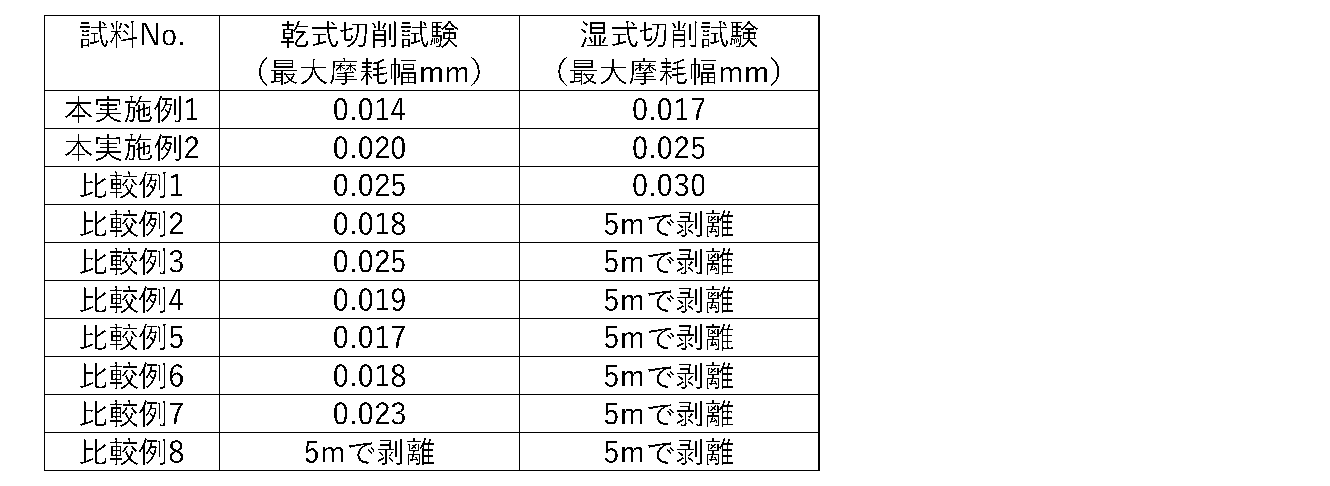
比較例8は硬質皮膜の被覆時に基材に印加する負圧のバイアス電圧の絶対値が大きく硬質皮膜に残留圧縮応力が過多に付与され乾式の切削試験でも早期の皮膜剥離が発生した。
また、結晶構造にhcp構造を含まない比較例1は湿式での切削試験において早期の皮膜剥離は発生しなかったが、本実施例に比べて皮膜組織が若干粗大であることで最大摩耗幅が大きくなった。
一方、本実施例は湿式および乾式での切削試験で優れた耐久性を示した。特に硬質皮膜がより微細になっている本実施例1は何れの切削試験においても最大摩耗幅が小さく耐摩耗性に優れており、耐久性に優れる被覆切削工具であった。
Claims (3)
- 基材と、前記基材上に形成される硬質皮膜とを備え、
前記硬質皮膜は、金属(半金属を含む)元素の総量に対して、Alが60原子%以上70原子%以下、Tiが20原子%以上40原子%以下、W、Cr、Ta、Nb、Zr、Mo、Vから選択される1種以上が1原子%以上10原子%以下であって、金属(半金属を含む)元素と窒素元素とAr元素の総量に対して、Arを0.01原子%以上0.15原子%以下で含有している窒化物であり、
前記硬質皮膜の結晶構造は面心立方格子構造であり、(111)面のX線回折ピークの半値幅は0.75°以上0.95°以下であることを特徴とする被覆切削工具。 - 前記硬質皮膜の(111)面のX線回折ピークの半値幅は0.78°以上0.95°以下であることを特徴とする請求項1に記載の被覆切削工具。
- 前記硬質皮膜は、透過型電子顕微鏡を用いた制限視野回折パターンの強度プロファイルにおいて、六方最密充墳構造のAlNに対応する回折ピーク強度を有さないことを特徴とする請求項1又は2に記載の被覆切削工具。
Priority Applications (5)
| Application Number | Priority Date | Filing Date | Title |
|---|---|---|---|
| US18/867,931 US20250332643A1 (en) | 2022-06-27 | 2023-06-23 | Coated cutting tool |
| JP2024530780A JPWO2024004873A1 (ja) | 2022-06-27 | 2023-06-23 | |
| CN202380042994.0A CN119278107A (zh) | 2022-06-27 | 2023-06-23 | 包覆切削工具 |
| EP23831315.9A EP4545225A4 (en) | 2022-06-27 | 2023-06-23 | COATED CUTTING TOOL |
| KR1020247038745A KR20250002597A (ko) | 2022-06-27 | 2023-06-23 | 피복 절삭 공구 |
Applications Claiming Priority (2)
| Application Number | Priority Date | Filing Date | Title |
|---|---|---|---|
| JP2022102962 | 2022-06-27 | ||
| JP2022-102962 | 2022-06-27 |
Publications (1)
| Publication Number | Publication Date |
|---|---|
| WO2024004873A1 true WO2024004873A1 (ja) | 2024-01-04 |
Family
ID=89382959
Family Applications (1)
| Application Number | Title | Priority Date | Filing Date |
|---|---|---|---|
| PCT/JP2023/023386 Ceased WO2024004873A1 (ja) | 2022-06-27 | 2023-06-23 | 被覆切削工具 |
Country Status (6)
| Country | Link |
|---|---|
| US (1) | US20250332643A1 (ja) |
| EP (1) | EP4545225A4 (ja) |
| JP (1) | JPWO2024004873A1 (ja) |
| KR (1) | KR20250002597A (ja) |
| CN (1) | CN119278107A (ja) |
| WO (1) | WO2024004873A1 (ja) |
Citations (6)
| Publication number | Priority date | Publication date | Assignee | Title |
|---|---|---|---|---|
| JP2003034858A (ja) * | 2001-07-23 | 2003-02-07 | Kobe Steel Ltd | 切削工具用硬質皮膜およびその製造方法並びに硬質皮膜形成用ターゲット |
| WO2014157688A1 (ja) | 2013-03-28 | 2014-10-02 | 日立ツール株式会社 | 被覆切削工具及びその製造方法 |
| JP2015110256A (ja) * | 2013-11-07 | 2015-06-18 | 三菱マテリアル株式会社 | 表面被覆切削工具 |
| WO2017094440A1 (ja) * | 2015-12-02 | 2017-06-08 | 三菱日立ツール株式会社 | 硬質皮膜、硬質皮膜被覆部材及びその製造方法、及び硬質皮膜の製造に用いるターゲット及びその製造方法 |
| WO2021167087A1 (ja) * | 2020-02-21 | 2021-08-26 | 株式会社Moldino | 被覆工具 |
| JP2022102962A (ja) | 2020-12-25 | 2022-07-07 | 美和子 堺 | 乾燥花の製造方法、乾燥植物の製造方法、食品の製造方法、および乾燥葉の製造方法 |
Family Cites Families (3)
| Publication number | Priority date | Publication date | Assignee | Title |
|---|---|---|---|---|
| ATE343659T1 (de) * | 2000-12-28 | 2006-11-15 | Kobe Steel Ltd | Hartstoffschicht für schneidwerkzeuge |
| JP3931325B2 (ja) * | 2001-10-03 | 2007-06-13 | 三菱マテリアル株式会社 | 高速切削加工で硬質被覆層がすぐれた耐摩耗性を発揮する表面被覆超硬合金製切削工具 |
| JP6844705B2 (ja) * | 2017-08-15 | 2021-03-17 | 株式会社Moldino | 被覆切削工具 |
-
2023
- 2023-06-23 EP EP23831315.9A patent/EP4545225A4/en active Pending
- 2023-06-23 JP JP2024530780A patent/JPWO2024004873A1/ja active Pending
- 2023-06-23 CN CN202380042994.0A patent/CN119278107A/zh active Pending
- 2023-06-23 US US18/867,931 patent/US20250332643A1/en active Pending
- 2023-06-23 KR KR1020247038745A patent/KR20250002597A/ko active Pending
- 2023-06-23 WO PCT/JP2023/023386 patent/WO2024004873A1/ja not_active Ceased
Patent Citations (6)
| Publication number | Priority date | Publication date | Assignee | Title |
|---|---|---|---|---|
| JP2003034858A (ja) * | 2001-07-23 | 2003-02-07 | Kobe Steel Ltd | 切削工具用硬質皮膜およびその製造方法並びに硬質皮膜形成用ターゲット |
| WO2014157688A1 (ja) | 2013-03-28 | 2014-10-02 | 日立ツール株式会社 | 被覆切削工具及びその製造方法 |
| JP2015110256A (ja) * | 2013-11-07 | 2015-06-18 | 三菱マテリアル株式会社 | 表面被覆切削工具 |
| WO2017094440A1 (ja) * | 2015-12-02 | 2017-06-08 | 三菱日立ツール株式会社 | 硬質皮膜、硬質皮膜被覆部材及びその製造方法、及び硬質皮膜の製造に用いるターゲット及びその製造方法 |
| WO2021167087A1 (ja) * | 2020-02-21 | 2021-08-26 | 株式会社Moldino | 被覆工具 |
| JP2022102962A (ja) | 2020-12-25 | 2022-07-07 | 美和子 堺 | 乾燥花の製造方法、乾燥植物の製造方法、食品の製造方法、および乾燥葉の製造方法 |
Non-Patent Citations (1)
| Title |
|---|
| See also references of EP4545225A4 |
Also Published As
| Publication number | Publication date |
|---|---|
| KR20250002597A (ko) | 2025-01-07 |
| US20250332643A1 (en) | 2025-10-30 |
| EP4545225A1 (en) | 2025-04-30 |
| EP4545225A4 (en) | 2026-02-18 |
| JPWO2024004873A1 (ja) | 2024-01-04 |
| CN119278107A (zh) | 2025-01-07 |
Similar Documents
| Publication | Publication Date | Title |
|---|---|---|
| EP3437774B1 (en) | Coated cutting tool | |
| KR102167200B1 (ko) | 피복 절삭 공구 | |
| JP6525310B2 (ja) | 被覆工具 | |
| JP7525669B2 (ja) | 被覆工具 | |
| JP7636492B2 (ja) | 被覆切削工具 | |
| EP4316707A1 (en) | Coated cutting tool | |
| JP2024047170A (ja) | 被覆切削工具 | |
| WO2020075356A1 (ja) | 切削工具及びその製造方法 | |
| JP7164828B2 (ja) | 被覆切削工具 | |
| JP7594220B2 (ja) | 被覆工具 | |
| JP6844704B2 (ja) | 被覆切削工具 | |
| EP4545225A1 (en) | Coated cutting tool | |
| WO2024048304A1 (ja) | 被覆工具 | |
| JP7760424B2 (ja) | 被覆部材 | |
| JP2024027836A (ja) | 被覆工具 | |
| WO2020039735A1 (ja) | 切削工具 | |
| JP2024075109A (ja) | 被覆切削工具 | |
| JP2024032363A (ja) | 被覆工具 | |
| JP2024132010A (ja) | 被覆切削工具 |
Legal Events
| Date | Code | Title | Description |
|---|---|---|---|
| 121 | Ep: the epo has been informed by wipo that ep was designated in this application |
Ref document number: 23831315 Country of ref document: EP Kind code of ref document: A1 |
|
| ENP | Entry into the national phase |
Ref document number: 20247038745 Country of ref document: KR Kind code of ref document: A |
|
| WWE | Wipo information: entry into national phase |
Ref document number: 1020247038745 Country of ref document: KR Ref document number: 18867931 Country of ref document: US |
|
| WWE | Wipo information: entry into national phase |
Ref document number: 202380042994.0 Country of ref document: CN |
|
| WWE | Wipo information: entry into national phase |
Ref document number: 2024530780 Country of ref document: JP |
|
| WWP | Wipo information: published in national office |
Ref document number: 202380042994.0 Country of ref document: CN |
|
| WWE | Wipo information: entry into national phase |
Ref document number: 2023831315 Country of ref document: EP |
|
| NENP | Non-entry into the national phase |
Ref country code: DE |
|
| ENP | Entry into the national phase |
Ref document number: 2023831315 Country of ref document: EP Effective date: 20250127 |
|
| WWP | Wipo information: published in national office |
Ref document number: 2023831315 Country of ref document: EP |
|
| WWP | Wipo information: published in national office |
Ref document number: 18867931 Country of ref document: US |