WO2024004941A1 - 手術支援システムおよび手術支援システムの制御方法 - Google Patents
手術支援システムおよび手術支援システムの制御方法 Download PDFInfo
- Publication number
- WO2024004941A1 WO2024004941A1 PCT/JP2023/023580 JP2023023580W WO2024004941A1 WO 2024004941 A1 WO2024004941 A1 WO 2024004941A1 JP 2023023580 W JP2023023580 W JP 2023023580W WO 2024004941 A1 WO2024004941 A1 WO 2024004941A1
- Authority
- WO
- WIPO (PCT)
- Prior art keywords
- surgical instrument
- endoscope
- control device
- support system
- axis
- Prior art date
- Legal status (The legal status is an assumption and is not a legal conclusion. Google has not performed a legal analysis and makes no representation as to the accuracy of the status listed.)
- Ceased
Links
Images







Classifications
-
- A—HUMAN NECESSITIES
- A61—MEDICAL OR VETERINARY SCIENCE; HYGIENE
- A61B—DIAGNOSIS; SURGERY; IDENTIFICATION
- A61B34/00—Computer-aided surgery; Manipulators or robots specially adapted for use in surgery
- A61B34/30—Surgical robots
-
- A—HUMAN NECESSITIES
- A61—MEDICAL OR VETERINARY SCIENCE; HYGIENE
- A61B—DIAGNOSIS; SURGERY; IDENTIFICATION
- A61B34/00—Computer-aided surgery; Manipulators or robots specially adapted for use in surgery
- A61B34/30—Surgical robots
- A61B34/37—Leader-follower robots
-
- A—HUMAN NECESSITIES
- A61—MEDICAL OR VETERINARY SCIENCE; HYGIENE
- A61B—DIAGNOSIS; SURGERY; IDENTIFICATION
- A61B34/00—Computer-aided surgery; Manipulators or robots specially adapted for use in surgery
- A61B34/70—Manipulators specially adapted for use in surgery
- A61B34/74—Manipulators with manual electric input means
-
- A—HUMAN NECESSITIES
- A61—MEDICAL OR VETERINARY SCIENCE; HYGIENE
- A61B—DIAGNOSIS; SURGERY; IDENTIFICATION
- A61B34/00—Computer-aided surgery; Manipulators or robots specially adapted for use in surgery
- A61B34/70—Manipulators specially adapted for use in surgery
- A61B34/77—Manipulators with motion or force scaling
-
- A—HUMAN NECESSITIES
- A61—MEDICAL OR VETERINARY SCIENCE; HYGIENE
- A61B—DIAGNOSIS; SURGERY; IDENTIFICATION
- A61B90/00—Instruments, implements or accessories specially adapted for surgery or diagnosis and not covered by any of the groups A61B1/00 - A61B50/00, e.g. for luxation treatment or for protecting wound edges
- A61B90/36—Image-producing devices or illumination devices not otherwise provided for
- A61B90/37—Surgical systems with images on a monitor during operation
-
- A—HUMAN NECESSITIES
- A61—MEDICAL OR VETERINARY SCIENCE; HYGIENE
- A61B—DIAGNOSIS; SURGERY; IDENTIFICATION
- A61B90/00—Instruments, implements or accessories specially adapted for surgery or diagnosis and not covered by any of the groups A61B1/00 - A61B50/00, e.g. for luxation treatment or for protecting wound edges
- A61B90/50—Supports for surgical instruments, e.g. articulated arms
-
- B—PERFORMING OPERATIONS; TRANSPORTING
- B25—HAND TOOLS; PORTABLE POWER-DRIVEN TOOLS; MANIPULATORS
- B25J—MANIPULATORS; CHAMBERS PROVIDED WITH MANIPULATION DEVICES
- B25J13/00—Controls for manipulators
-
- A—HUMAN NECESSITIES
- A61—MEDICAL OR VETERINARY SCIENCE; HYGIENE
- A61B—DIAGNOSIS; SURGERY; IDENTIFICATION
- A61B34/00—Computer-aided surgery; Manipulators or robots specially adapted for use in surgery
- A61B34/20—Surgical navigation systems; Devices for tracking or guiding surgical instruments, e.g. for frameless stereotaxis
- A61B2034/2046—Tracking techniques
- A61B2034/2048—Tracking techniques using an accelerometer or inertia sensor
-
- A—HUMAN NECESSITIES
- A61—MEDICAL OR VETERINARY SCIENCE; HYGIENE
- A61B—DIAGNOSIS; SURGERY; IDENTIFICATION
- A61B34/00—Computer-aided surgery; Manipulators or robots specially adapted for use in surgery
- A61B34/30—Surgical robots
- A61B2034/301—Surgical robots for introducing or steering flexible instruments inserted into the body, e.g. catheters or endoscopes
-
- A—HUMAN NECESSITIES
- A61—MEDICAL OR VETERINARY SCIENCE; HYGIENE
- A61B—DIAGNOSIS; SURGERY; IDENTIFICATION
- A61B90/00—Instruments, implements or accessories specially adapted for surgery or diagnosis and not covered by any of the groups A61B1/00 - A61B50/00, e.g. for luxation treatment or for protecting wound edges
- A61B90/06—Measuring instruments not otherwise provided for
- A61B2090/067—Measuring instruments not otherwise provided for for measuring angles
-
- A—HUMAN NECESSITIES
- A61—MEDICAL OR VETERINARY SCIENCE; HYGIENE
- A61B—DIAGNOSIS; SURGERY; IDENTIFICATION
- A61B90/00—Instruments, implements or accessories specially adapted for surgery or diagnosis and not covered by any of the groups A61B1/00 - A61B50/00, e.g. for luxation treatment or for protecting wound edges
- A61B90/36—Image-producing devices or illumination devices not otherwise provided for
- A61B90/37—Surgical systems with images on a monitor during operation
- A61B2090/372—Details of monitor hardware
-
- A—HUMAN NECESSITIES
- A61—MEDICAL OR VETERINARY SCIENCE; HYGIENE
- A61B—DIAGNOSIS; SURGERY; IDENTIFICATION
- A61B90/00—Instruments, implements or accessories specially adapted for surgery or diagnosis and not covered by any of the groups A61B1/00 - A61B50/00, e.g. for luxation treatment or for protecting wound edges
- A61B90/50—Supports for surgical instruments, e.g. articulated arms
- A61B2090/5025—Supports for surgical instruments, e.g. articulated arms with a counter-balancing mechanism
-
- A—HUMAN NECESSITIES
- A61—MEDICAL OR VETERINARY SCIENCE; HYGIENE
- A61B—DIAGNOSIS; SURGERY; IDENTIFICATION
- A61B90/00—Instruments, implements or accessories specially adapted for surgery or diagnosis and not covered by any of the groups A61B1/00 - A61B50/00, e.g. for luxation treatment or for protecting wound edges
- A61B90/50—Supports for surgical instruments, e.g. articulated arms
- A61B2090/508—Supports for surgical instruments, e.g. articulated arms with releasable brake mechanisms
Definitions
- the present disclosure relates to a surgical support system and a method of controlling the surgical support system.
- the surgical support system of US Patent Application Publication No. 2012/0283876 includes a master controller and a slave robot manipulator.
- the master control device includes a display section and an operation section.
- a surgical instrument is attached to the slave robot manipulator.
- An image of the surgical site taken by the endoscope is displayed on the display section of the master control device.
- the surgical instrument attached to the slave robot manipulator is moved by the operator operating the operating section of the master control device while viewing the image of the surgical site displayed on the display section.
- An object of the present invention is to provide a support system and a method for controlling a surgical support system.
- a surgical support system includes a first robot arm having an endoscope attached to its tip, and a second robot arm having a predetermined surgical instrument other than the endoscope attached to its tip.
- an operating device including an operating section that accepts operations on a predetermined surgical instrument or endoscope, and a control device that controls the movement of the predetermined surgical instrument or endoscope based on the accepted operation.
- the operating device includes: a display unit that displays an image taken by the endoscope and rotates to be tilted with respect to a horizontal plane; and a tilt detection sensor that detects a tilt of the display unit with respect to the horizontal plane; The control device corrects the translational movement of a predetermined surgical instrument based on the tilt detected by the tilt detection sensor.
- the control device performs translational movement of a predetermined surgical instrument based on the tilt detected by the tilt detection sensor that detects the tilt of the display unit with respect to the horizontal plane. Correct. Thereby, even if the inclination of the display unit with respect to the horizontal plane changes, the translational movement of the predetermined surgical instrument is corrected by the control device. Therefore, even if the inclination of the display section changes, the surgical instrument can be accurately translated in the desired direction intended by the operator. Further, based on the tilt detection sensor, the tilt of the display unit with respect to the horizontal plane can be detected relatively easily. Therefore, while easily detecting the inclination of the display section with respect to the horizontal plane, even if the inclination of the display section changes, it is possible to accurately translate the surgical instrument in the desired direction intended by the operator.
- a method for controlling a surgical support system includes a first robot arm having an endoscope attached to its tip, and a second robot arm having a predetermined surgical instrument other than the endoscope attached to its tip.
- a surgical device including a robot arm; an operating device including an operating unit that receives an operation for a predetermined surgical instrument or an endoscope; and a control device that controls moving the predetermined surgical instrument or endoscope based on the received operation.
- a control method for a surgical support system comprising: a control device for detecting a tilt with respect to a horizontal plane of a display unit on which an image taken by an endoscope is displayed and which rotates so as to be tilted with respect to a horizontal plane; and correcting translational movement of a predetermined surgical instrument based on the detected tilt.
- a method for controlling a surgical support system includes, as described above, an image captured by an endoscope is displayed, and a display section that rotates to be inclined with respect to a horizontal plane is tilted with respect to a horizontal plane.
- the method includes detecting the angle of the surgical instrument using a tilt detection sensor, and correcting the translational movement of a predetermined surgical instrument based on the detected tilt. Thereby, even if the inclination of the display unit with respect to the horizontal plane changes, the translational movement of the predetermined surgical instrument is corrected. Therefore, it is possible to provide a control method for a surgical support system that can accurately translate the surgical instrument in the desired direction intended by the operator even when the inclination of the display unit changes.
- the surgical support system can easily detect the tilt of the display unit with respect to the horizontal plane, and can accurately translate the surgical instruments in the desired direction intended by the operator even if the tilt of the display unit changes. can provide a control method.
- the surgical instrument can be accurately translated in the desired direction intended by the operator.
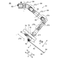
- FIG. 1 is a diagram showing the configuration of a surgical support system according to an embodiment.
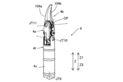
- FIG. 2 is a diagram illustrating the configuration of a robot arm according to one embodiment. It is a figure showing forceps.
- FIG. 3 is a perspective view showing the configuration of an arm operating section according to one embodiment.
- FIG. 3 is a diagram for explaining translational movement of a robot arm.
- FIG. 3 is a diagram for explaining rotational movement of a robot arm.
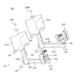
- FIG. 3 is a diagram showing an operation unit according to one embodiment.
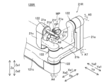
- FIG. 3 is a diagram showing the configuration of a right-hand operation section according to an embodiment.
- FIG. 3 is a diagram showing the configuration of a left-hand operation section according to an embodiment.
- FIG. 3 is a diagram illustrating the configuration of a foot pedal according to one embodiment.
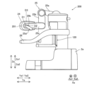
- FIG. 2 is a side view of a remote control device according to one embodiment.
- FIG. 3 is a diagram showing a state where the monitor is tilted.
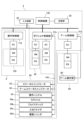
- FIG. 1 is a control block diagram of a surgical support system according to an embodiment.
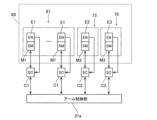
- FIG. 2 is a control block diagram of a robot arm according to one embodiment.
- FIG. 2 is a control block diagram of a remote control device according to an embodiment.
- FIG. 3 is a diagram showing an operator and an HC coordinate system.
- FIG. 3 is a diagram showing a surgical instrument, an endoscope, and an endoscope coordinate system.
- FIG. 6 is a diagram for explaining the operation when the operation unit receives an operation.
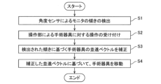
- FIG. 2 is a flow diagram of a method for controlling a surgical support system according to an embodiment. It is a side view of the remote control device by a modification.
- the surgical support system 100 includes a surgical support robot 1 and a remote control device 2.
- the surgical support robot 1 and the remote control device 2 are examples of a surgical device and a control device, respectively.
- the longitudinal direction of the shaft 4c of the surgical instrument 4 is defined as the Z direction.
- the distal end side of the surgical instrument 4 is defined as the Z1 side, and the proximal end side of the surgical instrument 4 is defined as the Z2 side.
- the direction perpendicular to the Z direction is defined as the X direction.
- the direction perpendicular to the Z direction and the X direction is defined as the Y direction.
- the direction along the vertical direction is referred to as the Za direction.
- One side in the Za direction is defined as the Za1 side, and the other side is defined as the Za2 side.
- the direction perpendicular to the Z direction is defined as the Xa direction.
- One side in the Xa direction is defined as the Xa1 side, and the other side is defined as the Xa2 side.
- the direction perpendicular to the Za direction and the Xa direction is the Ya direction.
- One side in the Ya direction is defined as the Ya1 side, and the other side is defined as the Ya2 side.
- the Xa direction and the Ya direction are directions along the horizontal plane.
- the surgical support robot 1 is placed in the operating room.
- the remote control device 2 is placed at a position separated from the surgical support robot 1.
- An operator such as a doctor inputs a command to the remote control device 2 to cause the surgical support robot 1 to perform a desired operation.
- the remote control device 2 transmits the input command to the surgical support robot 1.
- the surgical support robot 1 operates based on the received command.
- the surgical support robot 1 is placed in an operating room, which is a sterilized field.
- the surgical support robot 1 includes a medical cart 3, a positioner 40, an arm base 50, a plurality of robot arms 60, and an arm operation section 80.
- the medical cart 3 moves the positioner 40.
- the medical trolley 3 includes an input device 33.
- the input device 33 accepts operations for moving the positioner 40, the arm base 50, and the plurality of robot arms 60 and changing the posture, mainly in order to prepare for the surgery before the surgery.
- the medical trolley 3 includes an operation handle 34 that accepts steering by an operator.
- the positioner 40 is composed of, for example, a 7-axis articulated robot.
- the positioner 40 is placed on the medical cart 3.
- Positioner 40 adjusts the position of arm base 50.
- the positioner 40 moves the position of the arm base 50 three-dimensionally.
- the positioner 40 includes a base portion 41 and a plurality of link portions 42 connected to the base portion 41.
- the plurality of link parts 42 are connected to each other by joints 43.
- the arm base 50 is attached to the tip of the positioner 40.
- the base end of each of the plurality of robot arms 60 is attached to the arm base 50.
- the plurality of robot arms 60 can take a folded storage posture.
- the arm base 50 and the plurality of robot arms 60 are used while being covered with a sterile drape. Additionally, the robot arm 60 supports the surgical instrument 4.
- a plurality of robot arms 60 are arranged. Specifically, four robot arms 60a, 60b, 60c and 60d are arranged. Robot arms 60a, 60b, 60c and 60d have similar configurations. 60a, 60b, and 60d are examples of second robot arms. 60c is an example of the first robot arm.
- the robot arm 60 includes an arm section 61, a first link section 72, a second link section 73, and a translation mechanism section 70.
- the robot arm 60 has JT1, JT2, JT3, JT4, JT5, JT6, and JT7 axes as rotational axes, and a J8 axis as a linear motion axis.
- the JT1, JT2, JT3, JT4, JT5, JT6, and JT7 axes are rotational axes of the joints 64 of the arm portion 61.
- the JT7 axis is the rotation axis of the first link portion 72.
- the JT8 axis is a linear axis along which the translation mechanism section 70 moves the second link section 73 relative to the first link section 72 along the Z direction.
- the arm section 61 consists of a 7-axis articulated robot arm.
- the first link part 72 is arranged at the tip of the arm part 61.
- An arm operating section 80 is attached to the second link section 73.
- the translation mechanism section 70 is arranged between the first link section 72 and the second link section 73.
- a holder 71 that holds the surgical instrument 4 is arranged in the second link portion 73 .
- a surgical instrument 4 is attached to the tip of each of the plurality of robot arms 60.
- the surgical instruments 4 include, for example, replaceable instruments, an endoscope 6 for capturing images of the surgical site, and the like.
- the surgical instrument 4 as an instrument includes a driven unit 4a, a forceps 4b, and a shaft 4c connecting the driven unit 4a and the forceps 4b.
- the driven unit 4a, the shaft 4c, and the forceps 4b are arranged along the Z direction.
- the endoscope 6 is attached to the tip of one of the plurality of robot arms 60, for example, the robot arm 60c, and the endoscope 6 is attached to the tip of the remaining robot arms 60a, 60b, and 60d, for example. , surgical instruments 4 other than the endoscope 6 are attached.
- the endoscope 6 is attached to one of the two centrally located robot arms 60b and 60c among the four robot arms 60 that are arranged adjacent to each other.
- forceps 4b are arranged at the tip of the instrument.
- the tip of the instrument includes jointed instruments such as scissors, a grasper, a needle holder, a micro dissector, a stable applier, a tacker, a suction cleaning tool, a snare wire, and a clip applier.
- jointed instruments such as scissors, a grasper, a needle holder, a micro dissector, a stable applier, a tacker, a suction cleaning tool, a snare wire, and a clip applier.
- non-articulated instruments such as a cutting blade, a cautery probe, an irrigator, a catheter, and a suction orifice.
- the forceps 4b includes a first support 4e that rotatably supports the proximal ends of the jaw members 104a and 104b around the JT11 axis on the distal side, and a first support 4e that rotatably supports the proximal ends of the jaw members 104a and 104b around the JT11 axis on the distal side. and a second support body 4f that rotatably supports the second support body 4f.
- the shaft 4c rotates around the JT9 axis. Jaw member 104a and jaw member 104b open and close around the JT11 axis.
- a portion on the Z1 direction side, which is the tip end side, of the first support body 4e has a U-shape.
- the arm operating section 80 is attached to the robot arm 60. Specifically, the arm operation section 80 is attached to the second link section 73.
- the arm operation section 80 includes an enable switch 81, a joystick 82, a linear switch 83, a mode switching button 84, a mode indicator 84a, a pivot button 85, and an adjustment button 86. include.
- the enable switch 81 is a switch that allows or disallows movement of the robot arm 60 by the joystick 82 and linear switch 83.
- the joystick 82 is an operating tool for operating the movement of the surgical instrument 4 by the robot arm 60.
- the linear switch 83 is a switch for moving the surgical instrument 4 in a direction along the longitudinal direction of the surgical instrument 4.
- the mode switching button 84 is a button for switching between a translational movement mode shown in FIG. 5 and a rotational movement mode shown in FIG. 6 for the surgical instrument 4.
- Mode indicator 84a displays the switched mode.
- the pivot button 85 is a button for teaching the pivot position PP, which is the fulcrum of movement of the surgical instrument 4 attached to the robot arm 60.
- Adjustment button 86 is a button for optimizing the position of robot arm 60.
- the remote control device 2 As shown in FIG. 1, the remote control device 2 is placed, for example, in or outside the operating room.
- the remote control device 2 includes a main body portion 2a, an operation portion 120, a foot pedal 22, a touch panel 23, a monitor 24, a support arm 25, a support bar 26, a foot detection portion 27, and an angle shown in FIG. It includes a sensor 29a and a switch section 29b shown in FIG. 11.
- the monitor 24 is an example of a display section.
- the angle sensor 29a is an example of a tilt detection sensor.
- the operation unit 120 accepts operations on the endoscope 6 or a surgical instrument 4 other than the endoscope 6.
- the operating section 120 is supported by the main body section 2a.
- the operation unit 120 includes a left-hand operation unit 120L that is placed on the left side and is operated by the operator's left hand when viewed from an operator such as a doctor, and a left-hand operation unit 120L that is placed on the right side and is operated by the operator's right hand. and a right-hand operation section 120R operated by the right-hand operation section 120R.
- the configuration of the left-hand operation section 120L and the configuration of the right-hand operation section 120R are similar.
- the operating section 120 includes a substantially L-shaped arm 121 and an operating handle 21.
- the arm 121 includes a link portion 121a, a link portion 121b, and a link portion 121c.
- the upper end side of the link part 121a is attached to the main body part 2a so as to be rotatable around the A1 axis along the vertical direction.
- the upper end side of the link part 121b is attached to the lower end side of the link part 121a so as to be rotatable around the A2 axis along the horizontal direction.
- One end side of the link part 121c is attached to the lower end side of the link part 121b so as to be rotatable around the A3 axis along the horizontal direction.
- the operating handle 21 is attached to the other end of the link portion 121c so as to be rotatable around the A4 axis.
- Each link portion is connected by a joint 122.
- the arm 121 supports the operating handle 21.
- the arm 121 supports the operating handle 21 movably within a predetermined three-dimensional operating range. Specifically, the arm 121 supports the operating handle 21 so as to be movable in the up-down direction, left-right direction, and front-back direction.
- the robot arm 60 is moved three-dimensionally to correspond to the three-dimensional operation of the arm 121.
- the operating handle 21 includes an operating handle 21R that is operated by the operator's right hand as shown in FIG. 8, and an operating handle 21L that is operated by the operator's left hand as shown in FIG.
- FIG. 8 shows the standard posture of the right hand operating section 120R
- FIG. 9 shows the standard posture of the left hand operating section 120L.
- the configuration of the operating handle 21R and the configuration of the operating handle 21L are similar.
- the operating handle 21 includes a link portion 21a, a link portion 21b, a link portion 21c, and a link portion 21d operated by an operator such as a doctor.
- the link portion 21a rotates around the A4 axis.
- the link portion 21b is attached to the link portion 21a so as to be rotatable around the A5 axis.
- the link portion 21c is rotatably attached to the link portion 21b around the A6 axis.
- the link portion 21d is rotatably attached to the link portion 21c around the A7 axis.
- Each link portion is connected by a joint 122.
- the link portion 21a, the link portion 21b, and the link portion 21c each have an L-shape.
- the operating handle 21 includes a pair of grip members 21f that are opened and closed by the operator.
- the grip member 21f is made of an elongated plate-like lever member, and the proximal ends of the pair of grip members 21f are rotatably connected to the proximal end G1 of the link portion 21d.
- a cylindrical finger insertion portion 21e is arranged on the grip member 21f. The operator inserts the fingers of his right hand into the pair of finger insertion portions 21e and operates the operating handle 21R. The operator inserts the fingers of his left hand into the pair of finger insertion parts 21e and operates the operating handle 21L.
- the pair of grip members 21f have their base ends connected to the link portion 21d, and by increasing or decreasing the angle between the pair of grip members 21f, the jaw members 104a and 104b can be opened. The angle is changed.
- a magnet is arranged on one side of the grip member 21f, and a Hall sensor is arranged on the link part 21d.
- the magnet and the Hall sensor function as an angle detection sensor, and the Hall sensor outputs the opening angle.
- a Hall sensor may be disposed on the grip member 21f, and a magnet may be disposed on the link portion 21d.
- a magnet or a Hall sensor may be arranged as an angle detection sensor on both grip members 21f.
- the intersection of the plurality of rotational axes of the operation unit 120 is called a gimbal point GP.
- the gimbal point GP is a point where the A4 axis, the A5 axis, the A6 axis, and the A7 axis intersect.
- the gimbal point GP is located at the link portion 21d to which the pair of grip members 21f is attached.
- the gimbal point GP exists separately for each of the left-hand operation section 120L and the right-hand operation section 120R.
- a plurality of foot pedals 22 are provided to perform functions related to the surgical instrument 4. Further, the plurality of foot pedals 22 are arranged on the base section 28.
- the foot pedal 22 includes a switching pedal 22a, a clutch pedal 22b, a camera pedal 22c, an incision pedal 22d, and a coagulation pedal 22e.
- the switching pedal 22a, the clutch pedal 22b, the camera pedal 22c, the incision pedal 22d, and the coagulation pedal 22e are operated by the operator's feet.
- the incision pedal 22d includes an incision pedal 22dR for the right robot arm 60 and an incision pedal 22dL for the left robot arm 60.
- the coagulation pedal 22e includes a coagulation pedal 22eR for the right robot arm 60 and a coagulation pedal 22eL for the left robot arm 60.
- the switching pedal 22a switches the robot arm 60 operated by the operating handle 21.
- the clutch pedal 22b performs a clutch operation that temporarily disconnects the robot arm 60 and the operating handle 21. While the clutch pedal 22b is depressed by the operator, the operation by the operating handle 21 is no longer transmitted to the robot arm 60. Further, while the camera pedal 22c is depressed by the operator, the robot arm 60 to which the endoscope 6 is attached can be operated by the operating handle 21. While the incision pedal 22d or the coagulation pedal 22e is depressed by the operator, the electrosurgical device is activated.
- the foot detection unit 27 detects the foot of the operator who operates the foot pedal 22.
- the foot detection unit 27 detects a foot located above the foot pedal 22 in a hovering state.
- the foot detection section 27 is arranged on the base section 28.
- the monitor 24 is a scope-type display device for displaying images taken by the endoscope 6.
- the monitor 24 rotates so as to be inclined with respect to the horizontal plane. Specifically, the monitor 24 rotates around the D1 axis along the Xa direction.
- the D1 axis is an example of a first axis.
- the support arm 25 supports the monitor 24 so that the height of the monitor 24 matches the height of the face of an operator such as a doctor.
- the support arm 25 includes a first link portion 25a, a second link portion 25b, a third link portion 25c, and a grip portion 25d.
- One end of the first link portion 25a is attached to the main body portion 2a.
- a joint JT21 is arranged at one end of the first link portion 25a.
- the other end of the first link portion 25a and one end of the second link portion 25b are connected by a joint JT22.
- the other end of the second link portion 25b and one end of the third link portion 25c are connected by a joint JT23.
- the monitor 24 is rotatably attached to the third link portion 25c.
- the grip portion 25d is arranged on the third link portion 25c.
- the grip portion 25d is arranged on both the Xa1 side and the Xa2 side of the third link portion 25c.
- the first link portion 25a and the second link portion 25b are examples of link portions.
- the third link portion 25c is an example of a link portion and a holding portion.
- a spring SP1 is arranged at the base end of the first link portion 25a.
- the first link portion 25a is lifted by the spring SP1.
- a spring SP2 is arranged in the first link portion 25a.
- the second link portion 25b is lifted by the spring SP2.
- a spring SP3 is arranged in the second link portion 25b.
- the third link portion 25c is lifted by the spring SP3.
- a brake BRK1 is arranged on the base end side of the first link portion 25a. Brake BRK1 fixes joint JT21 so that it does not rotate.
- a brake BRK2 is arranged at the joint JT23 where the second link portion 25b and the third link portion 25c are connected. Brake BRK2 fixes joint JT23 so that it does not rotate.
- Brake BRK1 and brake BRK2 are electromagnetic brakes of non-excitation operation type, and are configured so that joint JT21 and joint JT23 do not move even if an external force is applied. Note that only one or two of the springs SP1, SP2, and SP3 may be arranged. Further, only the brake BRK1 or the brake BRK2 may be arranged. Further, a brake may also be provided at the joint JT22.
- the switch section 29b switches between a state in which the change in attitude of the support arm 25 is permitted and a state in which it is not permitted.
- the switch section 29b is arranged on the grip section 25d.
- the brake BRK1 and the brake BRK2 are released, and when the operator grips and moves the grip part 25d, the attitude of the support arm 25 can be changed.
- the angle of inclination of the monitor 24 with respect to the horizontal plane can be changed by the operator holding and tilting the grip portion 25d.
- the brake BRK3 may be arranged so as to fix the rotation of the monitor 24 and the third link portion 25c. It may be configured such that when the operator presses the switch portion 29b, in addition to changing the posture of the support arm 25, the brake BRK3 is released, thereby making it possible to change the inclination angle of the monitor 24 with respect to the horizontal plane. good.
- the angle sensor 29a detects the inclination of the monitor 24 with respect to the horizontal plane.
- the monitor 24 rotates around the D1 axis with respect to the third link portion 25c.
- the angle sensor 29a detects the rotation angle ⁇ of the monitor 24 around the D1 axis along the horizontal plane.
- the angle sensor 29a detects the rotation angle ⁇ of the monitor 24 with respect to the third link portion 25c.
- the angle sensor 29a is, for example, an encoder that detects the rotation angle ⁇ of the monitor 24.
- the touch panel 23 is arranged on the support bar 26.
- the surgical support robot 1 can be operated by the remote control device 2.
- the operator operates the operating section 120 and the foot pedal 22 while visually checking the affected area on the monitor 24.
- a command is input to the remote control device 2.
- the command input to the remote control device 2 is transmitted to the surgical support robot 1.
- Support arm 25 is an example of a support section.
- the surgical support system 100 includes a control device 130, an arm control section 31a, a positioner control section 31b, and an operation control section 110.
- the control device 130 is arranged inside the medical trolley 3 so as to communicate with the arm control section 31a and the positioner control section 31b, and controls the entire surgical support system 100. Specifically, the control device 130 communicates with and controls each of the arm control section 31a, positioner control section 31b, and operation control section 110. The control device 130, the arm control section 31a, the positioner control section 31b, and the operation control section 110 are connected via a LAN or the like. The control device 130 is arranged inside the medical trolley 3.
- the arm control section 31a is arranged for each of the plurality of robot arms 60. That is, inside the medical trolley 3, a plurality of arm control units 31a corresponding to the number of the plurality of robot arms 60 are arranged.
- the input device 33 is connected to the control device 130 via a LAN or the like.
- the status indicator 53, the arm status indicator 54, the operating handle 34, the throttle 34a, the joystick 33b, the stabilizer 34c, the electric cylinder 34d, and the positioner control unit 31b communicate serially through a communication network that allows them to share information with each other through wiring 145. It is connected.
- FIG. 13 shows that the status indicator 53, arm status indicator 54, etc. are all connected to one wiring 145, in reality, the status indicator 53, arm status indicator 54, and operation Wiring 145 is arranged for each handle 34, throttle 34a, joystick 33b, stabilizer 34c, and electric cylinder 34d.
- the arm portion 61 is provided with a plurality of servo motors M1, an encoder E1, and a reduction gear so as to correspond to the plurality of joints 64.
- Encoder E1 detects the rotation angle of servo motor M1.
- the speed reducer slows down the rotation of the servo motor M1 and increases the torque.
- a servo control section C1 for controlling the servo motor M1 is arranged adjacent to the arm control section 31a.
- an encoder E1 for detecting the rotation angle of the servo motor M1 is electrically connected to the servo control section C1.
- a servo motor M2 for rotating a driven member disposed in the driven unit 4a of the surgical instrument 4, an encoder E2, and a speed reducer are arranged in the second link portion 73.
- Encoder E2 detects the rotation angle of servo motor M2.
- the speed reducer slows down the rotation of the servo motor M2 and increases the torque.
- a servo control section C2 for controlling a servo motor M2 that drives the surgical instrument 4 is arranged on the medical cart 3.
- An encoder E2 for detecting the rotation angle of the servo motor M2 is electrically connected to the servo control unit C2. Note that a plurality of servo motors M2, encoders E2, and servo control units C2 are each arranged.
- the translation mechanism section 70 is provided with a servo motor M3 for translationally moving the surgical instrument 4, an encoder E3, and a speed reducer.
- Encoder E3 detects the rotation angle of servo motor M3.
- the speed reducer slows down the rotation of the servo motor M3 and increases the torque.
- a servo control unit C3 for controlling a servo motor M3 that translates the surgical instrument 4 is arranged on the medical cart 3.
- An encoder E3 for detecting the rotation angle of the servo motor M3 is electrically connected to the servo control unit C3.
- the positioner control section 31b is arranged on the medical cart 3.
- the positioner control unit 31b controls the positioner 40 and the medical trolley 3.
- a servo motor SM, an encoder EN, a speed reducer, and a servo control unit SC are arranged in the positioner 40 so as to correspond to the plurality of joints 43 of the positioner 40.
- the medical cart 3 is provided with a servo motor SM that drives each of the plurality of front wheels of the medical cart 3, an encoder EN, a speed reducer, a servo control unit SC, and a brake.
- the operation unit 120 includes servo motors M6a, M6b, M6c, M6d, and M6e corresponding to each of the rotation axes A1, A2, A3, A4, A5, A6, and A7. , M6f and M6g are arranged. Further, the medical trolley 3 is provided with servo control units C6a, C6b, C6c, C6d, C6e, C6f, and C6g for controlling each servo motor. Encoders E6a, E6b, E6c, E6d, E6e, E6f, and E6g for detecting the rotation angle of each servo motor are electrically connected to each servo control section. Note that each servo motor, each servo control section, and each encoder are provided in the left-hand operation section 120L and the right-hand operation section 120R, respectively.
- the control device 130 controls each servo motor via the operation control unit 110 in accordance with the attitude of the operation unit 120 so as to generate a torque that cancels the gravitational torque generated on the rotational axis of each servo motor. . This allows the operator to operate the operating section 120 with relatively small force.
- the control device 130 controls each servo motor to generate torque on each rotation axis of each servo motor via the operation control unit 110 in response to the operation of the operation unit 120, and to assist the operator's operation. . This allows the operator to operate the operating section 120 with relatively small force.
- the control device 130 controls the movement of the endoscope 6 or a surgical instrument 4 other than the endoscope 6 based on the operation accepted by the operation unit 120. Specifically, as shown in FIGS. 8 and 9, the control device 130 sets the operating unit reference point MP for the operating unit 120.
- the operating unit reference point MP is also called a mapping point.
- the operating unit reference point MP is set, for example, to the gimbal point GP.
- the control device 130 sets a surgical instrument reference point CP shown in FIG. 3 for the surgical instrument 4.
- the control device 130 controls the surgical instrument 4 to move when the operating section 120 is operated so that the surgical instrument reference point CP moves in accordance with the movement of the operating section reference point MP.
- the surgical instrument reference point CP is set at the center of the Z1 direction side portion of the first support 4e in the JT 11 axial direction.
- the surgical instrument reference point CP is called a tool center point or clevis point.
- a coordinate system of the operation unit 120 is set in the operation unit 120.
- the coordinate system of the operation unit 120 will be referred to as an HC coordinate system.
- a coordinate system of the endoscope 6 is set in the endoscope 6.
- the coordinate system of the endoscope 6 will be referred to as an endoscope coordinate system.
- the surgical instrument 4 moves along the Yc direction of the endoscope coordinate system, which is the direction in which the endoscope 6 extends. .
- the inventor of the present invention found that the direction in which the operator operates the operating unit 120 changes due to the change in the direction of the operator's line of sight when viewing the monitor 24. For example, suppose that the operator attempts to translate the surgical instrument 4 along the Yc direction of the endoscopic coordinate system when the monitor 24 is tilted diagonally downward. At this time, it has been found that the operator moves the operating unit 120 not in the Yb direction of the HC coordinate system, but in a diagonal downward direction intersecting the Yb direction, as shown in the translation vector uh shown in FIG. Therefore, the surgical instrument 4 is translated in a direction different from the operator's intention. Note that uh in FIG. 16 is a translation vector representing the direction in which the operating unit 120 is moved as seen from the HC coordinate system.
- the control device 130 corrects the translational movement of the surgical instrument 4 based on the inclination detected by the angle sensor 29a.
- the surgical instrument 4 is, for example, an instrument having forceps 4b disposed at its tip.
- the control device 130 causes the surgical instrument 4 to move along the direction in which the endoscope 6 extends based on the inclination detected by the angle sensor 29a.
- the direction of translation of the surgical instrument 4 is corrected so that the surgical instrument 4 is translated. That is, even when the translation vector uh of the operation unit 120 is directed diagonally upward, the control device 130 corrects the translation vector uf so that it follows the Yc direction of the endoscope coordinate system.
- uf is a translation vector representing the moving direction of the forceps 4b as seen from the robot reference coordinate system.
- the control device 130 controls the operation of the surgical instrument 4 when an operation for translating the surgical instrument 4 in the front-rear direction as seen from the operator is received.
- the direction of translation is not corrected. That is, when the monitor 24 is disposed along a horizontal plane and an operation for translational movement along the Yb direction of the HC coordinate system is received, the control device 130 moves the monitor 24 along the Yc direction of the endoscope coordinate system.
- the surgical instrument 4 is translated so that the surgical instrument 4 is translated.
- the control device 130 controls the posture of the endoscope 6 based on the coordinate system of the endoscope 6.
- the direction of translation of the surgical instrument 4 is corrected based on a posture term representing the position and a correction term that corrects the posture term based on the inclination detected by the angle sensor 29a.
- the control device 130 changes the translation vector uh of the surgical instrument 4 based on the coordinate system of the operation unit 120 to the translation vector uh based on the coordinate system of the endoscope 6.
- the translation vector uf of the surgical instrument 4 is corrected by multiplying the posture matrix Hcam of the endoscope 6 by the posture correction matrix Rx based on the inclination detected by the angle sensor 29a.
- uf Hcam ⁇ Rx ⁇ uh ⁇ (1)
- Hcam is a posture matrix of the camera coordinate system viewed from the robot reference coordinate system.
- Rx is an attitude correction matrix according to the rotation angle ⁇ of the monitor 24 around the D1 axis.
- Rx is changed according to the rotation angle ⁇ .
- Rx corresponds to the inclination of the monitor 24 with respect to the horizontal plane. That is, the control device 130 corrects the translational movement of the surgical instrument 4 based on the rotation angle ⁇ about the D1 axis detected by the angle sensor 29a.
- the control device 130 corrects the translational movement of the surgical instrument 4 based on the inclination detected by the angle sensor 29a during a surgery in which an operation on the surgical instrument 4 is accepted by the remote control device 2. Specifically, the control device 130 corrects the translational movement of the surgical instrument 4 based on the inclination detected by the angle sensor 29a while following, which is an operation of moving the surgical instrument 4, is performed. do. Furthermore, when the operator presses the switch part 29b to change the inclination angle of the monitor 24 with respect to the horizontal plane during surgery, the above equation ( 1) Rx is changed. Then, the translational movement of the surgical instrument 4 is corrected based on the changed Rx.
- a method of calculating the input value of the operation unit 120 when an operation by the operator is accepted will be described.
- an operation by the operator is accepted by the operation unit 120.
- the axis values of the A1 axis, A2 axis, A3 axis, A4 axis, A5 axis, A6 axis, and A7 axis of the operation unit 120 are input to the operation control unit 110.
- the control device 130 performs forward kinematics calculations based on each axis value input to the operation control unit 110.
- a homogeneous transformation matrix representing the displacement and rotation of the operating unit reference point MP from the reference posture is updated as an input value from the operating unit 120.
- Forward kinematics calculation is a means of calculating the displacement and rotation of a focused part of the mechanism from the axis values of the link mechanism.
- the control device 130 transforms the homogeneous transformation matrix representing the input from the operation unit 120 according to the viewing direction of the endoscope 6. At this time, the translational movement of the surgical instrument 4 is corrected based on the above formula (1).
- the obtained homogeneous transformation matrix includes a translational component for the translational movement of the surgical instrument 4 and a translational component for the rotation of the surgical instrument 4, which produce a movement corresponding to the input of the operating unit 120 within the field of view of the endoscope 6. rotational component.
- the control device 130 performs scaling on the translational component and the rotational component.
- Scaling means multiplying the translational component and the rotational component by a scaling value that is the ratio between the amount of operation received by the operation unit 120 and the amount of movement of the surgical instrument 4 that actually moves.
- the control device 130 calculates a target homogeneous transformation matrix based on the scaled translational and rotational components.
- the control device 130 performs inverse kinematics calculations on the target homogeneous transformation matrix.
- the control device 130 calculates target axis values for the robot arm 60 and the surgical instrument 4 by inverse kinematic calculation.
- step S1 the angle sensor 29a detects the tilt of the monitor 24 with respect to the horizontal plane.
- step S2 the operation unit 120 accepts an operation on the surgical instrument 4.
- step S3 the control device 130 corrects the translation vector of the surgical instrument 4 using the above equation (1) based on the detected tilt.
- step S4 the control device 130 controls the movement of the surgical instrument 4 based on the corrected translation vector.
- the control device 130 corrects the translational movement of the surgical instrument 4 based on the inclination detected by the angle sensor 29a that detects the inclination of the monitor 24 with respect to the horizontal plane. Thereby, even if the inclination of the monitor 24 with respect to the horizontal plane changes, the translational movement of the surgical instrument 4 is corrected by the control device 130. Therefore, even if the tilt of the monitor 24 changes, the surgical instrument 4 can be accurately translated in the desired direction intended by the operator. Furthermore, the inclination of the monitor 24 with respect to the horizontal plane can be detected relatively easily based on the angle sensor 29a. Therefore, while the inclination of the monitor 24 with respect to the horizontal plane is easily detected, even if the inclination of the monitor 24 changes, the surgical instrument 4 can be accurately translated in the desired direction intended by the operator.
- the control device 130 controls the surgical instrument 4 to translate along the direction in which the endoscope 6 extends based on the inclination detected by the angle sensor 29a. , correct the direction of translation of the surgical instrument 4. Thereby, even if the inclination of the monitor 24 changes, the surgical instrument 4 can be accurately translated along the direction in which the endoscope 6 extends.
- the control device 130 When an operation for translational movement of the surgical instrument 4 is accepted, the control device 130 performs a translation operation based on the attitude term representing the attitude of the endoscope 6 based on the coordinate system of the endoscope 6 and the inclination detected by the angle sensor 29a.
- the direction of translation of the surgical instrument 4 is corrected based on the correction term for correcting the posture term.
- the posture term representing the posture of the endoscope 6 is corrected by the correction term based on the inclination detected by the angle sensor 29a, so the surgical instrument 4 is appropriately translated so as to follow the posture of the endoscope 6. It can be moved.
- the control device 130 changes the translational vector uh of the surgical instrument 4 based on the coordinate system of the operation unit 120 to the translational vector uh of the endoscope 6 based on the coordinate system of the endoscope 6.
- the translation vector uf of the surgical instrument 4 is corrected by multiplying the posture matrix Hcam by the posture correction matrix Rx based on the inclination detected by the angle sensor 29a.
- the translation vector uf of the surgical instrument 4 is corrected by the posture matrix Hcam of the endoscope 6 and the posture correction matrix Rx, so that the surgical instrument 4 is appropriately translated so as to follow the posture of the endoscope 6. be able to.
- the remote control device 2 includes a support arm 25 that supports a monitor 24.
- the support arm 25 includes a first link portion 25a, a second link portion 25b, a third link portion 25c, joints JT21, JT22, and JT23, a brake BRK1 that fixes the joint JT21 so that it does not rotate, and a joint JT23. It includes a brake BRK2 that is fixed so as not to rotate, a spring SP1 that lifts the first link part 25a, a spring SP2 that lifts the second link part 25b, and a spring SP3 that lifts the third link part 25c.
- the joints JT21 and JT23 can be fixed by the brakes BRK1 and BRK2 so that they do not move. Further, since the weights of the support arm 25 and the monitor 24 are supported by the springs SP1, SP2, and SP3, the posture of the support arm 25 is maintained.
- the control device 130 corrects the translational movement of the surgical instrument 4 based on the inclination detected by the angle sensor 29a during a surgery in which an operation on the surgical instrument 4 is accepted by the remote control device 2. Thereby, even if the inclination of the monitor 24 is changed during surgery, the surgical instrument 4 can be translated in the desired direction intended by the operator.
- the angle sensor 29a detects the rotation angle ⁇ of the monitor 24 about the D1 axis along the horizontal plane, and the control device 130 controls the surgical instrument based on the rotation angle ⁇ about the D1 axis detected by the angle sensor 29a. Correct the translation of 4. Thereby, the inclination of the monitor 24 with respect to the horizontal plane can be easily detected based on the rotation angle ⁇ of the monitor 24 around the D1 axis.
- the remote control device 2 includes a switch section 29b that switches between a state in which changing the inclination angle of the monitor 24 with respect to the horizontal plane is permitted and a state in which it is not permitted. Thereby, the switch portion 29b can prevent the tilt of the monitor 24 from being changed at a timing not intended by the operator.
- the direction of the translational movement of the surgical instrument 4 is corrected so that the surgical instrument 4 is translated along the Yc direction of the endoscopic coordinate system in which the endoscope 6 extends.
- This disclosure is not limited thereto.
- the direction of translation of the surgical instrument 4 may be corrected so that the surgical instrument 4 is translated along a direction other than the Yc direction of the endoscopic coordinate system.
- the translation vector is corrected based on the above equation (1), but the present disclosure is not limited to this.
- the translation vector may be corrected based on a formula other than the above formula (1).
- a state in which the translational movement of the surgical instrument 4 is corrected and a state in which the translational movement of the surgical instrument 4 is not corrected may be switched based on an operation by the operator.
- an example has been shown in which the control device 130 corrects the translational movement of the surgical instrument 4 based on the rotation angle ⁇ of the monitor 24 around the D1 axis detected by the angle sensor 29a.
- an acceleration sensor 201 may be arranged as in a modified remote control device 200 shown in FIG.
- the acceleration sensor 201 is arranged on the monitor 24 at the end of the third link portion 25c of the remote control device 200 in the Ya1 direction. Acceleration sensor 201 detects the inclination of monitor 24 with respect to at least a horizontal plane.
- the acceleration sensor 201 detects the rotation angle of the monitor 24 around the D1 axis along the horizontal plane, around the D2 axis that is perpendicular to the D1 axis and along the horizontal plane, and around the D3 axis along the vertical direction. do. Thereby, the tilt of the monitor 24 can be easily detected by the acceleration sensor 201. Further, the acceleration sensor 201 can easily detect a three-dimensional change in the tilt of the monitor 24.
- the control device 130 corrects the translational movement of the surgical instrument 4 based on the rotation angles around the D1 axis, the D2 axis, and the D3 axis detected by the acceleration sensor 201.
- the surgical instrument 4 can be accurately translated in the desired direction intended by the operator.
- the translational movement of the surgical instrument 4 is corrected based on the following equation (2).
- uf Hcam ⁇ Mcomp ⁇ uh...(2)
- Mcomp is an attitude correction matrix that is changed according to the rotation angle of the monitor 24 around the D1 axis, the D2 axis, and the D3 axis.
- Acceleration sensor 201 is an example of a tilt detection sensor.
- the D2 axis and the D3 axis are examples of the second axis and the third axis, respectively.
- the switch unit 29b switches between a state in which the change in the tilt angle of the monitor 24 with respect to the horizontal plane is permitted and a state in which it is not permitted, but the present disclosure is not limited to this.
- the inclination angle of the monitor 24 may be freely changed by the operator without the switch portion 29b being provided.
- the present disclosure is not limited to this.
- the number of robot arms 60 may be any other number as long as at least one is provided.
- the arm section 61 and the positioner 40 are composed of a 7-axis articulated robot, but the present disclosure is not limited to this.
- the arm portion 61 and the positioner 40 may be composed of an articulated robot having an axis configuration other than a seven-axis articulated robot.
- Axis configurations other than the 7-axis articulated robot include, for example, 6 axes and 8 axes.
- the surgical support robot 1 includes the medical trolley 3, the positioner 40, and the arm base 50, but the present disclosure is not limited to this.
- the medical cart 3, the positioner 40, and the arm base 50 are not necessarily necessary, and the surgical support robot 1 may be configured only with the robot arm 60.
- circuits may be implemented using general purpose processors, special purpose processors, integrated circuits, ASICs (Application Specific Integrated Circuits), conventional circuits, and/or those configured or programmed to perform the disclosed functions.
- Processors are considered processing circuits or circuits because they include transistors and other circuits.
- a circuit, unit, or means is hardware that performs the recited functions or is hardware that is programmed to perform the recited functions.
- the hardware may be the hardware disclosed herein or other known hardware that is programmed or configured to perform the recited functions.
- the hardware is a processor, which is considered a type of circuit
- the circuit, means or unit is a combination of hardware and software, the software being used to configure the hardware and/or the processor.
- a surgical device including a first robot arm having an endoscope attached to its tip; and a second robot arm having a predetermined surgical instrument other than the endoscope attached to its tip; an operating device including an operating section that receives an operation on the predetermined surgical instrument or the endoscope; a control device that controls the movement of the predetermined surgical instrument or the endoscope based on the accepted operation,
- the operating device includes: a display unit that displays an image taken by the endoscope and rotates to be inclined with respect to a horizontal plane; a tilt detection sensor that detects a tilt of the display unit with respect to a horizontal plane, A surgical support system, wherein the control device corrects translational movement of the predetermined surgical instrument based on the tilt detected by the tilt detection sensor.
- the control device When a translational movement operation for the predetermined surgical instrument is accepted, the control device includes an attitude term representing an attitude of the endoscope based on a coordinate system of the endoscope, and an attitude term detected by the inclination detection sensor.
- the control device When a translational movement operation for the predetermined surgical instrument is accepted, the control device includes a translation vector of the predetermined surgical instrument based on the coordinate system of the operation section, and a translation vector of the predetermined surgical instrument based on the coordinate system of the endoscope.
- the surgical support system according to item 2 wherein the translational movement vector of the predetermined surgical instrument is corrected by multiplying the posture matrix of the endoscope and the posture correction matrix based on the tilt detected by the tilt detection sensor. .
- the operating device includes a support arm that supports the display section, The support arm is multiple link parts, a plurality of joints connecting the plurality of link parts; The surgical support system according to any one of items 1 to 3, including a brake that fixes at least one joint of the plurality of joints from rotating.
- the operating device includes a support arm that supports the display section, The support arm is multiple link parts, a joint connecting the plurality of link parts; The surgical support system according to any one of items 1 to 4, including a spring that lifts at least one link portion of the plurality of link portions.
- (Item 6) Item 1, wherein the control device corrects the translational movement of the predetermined surgical instrument based on the tilt detected by the tilt detection sensor during a surgery in which the operating device accepts an operation on the predetermined surgical instrument.
- the surgical support system according to any one of items 5 to 5.
- the tilt detection sensor detects a rotation angle of the display unit around a first axis along a horizontal plane
- the control device corrects the translational movement of the predetermined surgical instrument based on the rotation angle about the first axis detected by the tilt detection sensor, according to any one of items 1 to 6.
- the tilt detection sensor detects a rotation angle of the display unit around a first axis along a horizontal plane, around a second axis perpendicular to the first axis and along the horizontal plane, and around a third axis along the vertical direction. detect, Item 1, wherein the control device corrects the translational movement of the predetermined surgical instrument based on rotation angles about the first axis, the second axis, and the third axis detected by the tilt detection sensor.
- the surgical support system according to any one of items 6 to 6.
- the operating device includes a holding part that holds the display part, The display unit rotates around a first axis along a horizontal plane with respect to the holding unit,
- the surgical support system according to any one of items 1 to 8, wherein the tilt detection sensor includes an angle sensor that detects a rotation angle of the display unit about the first axis.
- the tilt detection sensor includes an acceleration sensor that detects a tilt of the display unit with respect to at least a horizontal plane.
- a surgical device including a first robot arm having an endoscope attached to its tip; and a second robot arm having a predetermined surgical instrument other than the endoscope attached to its tip; an operating device including an operating section that receives an operation for the predetermined surgical instrument or the endoscope; and a control device that controls moving the predetermined surgical instrument or the endoscope based on the accepted operation.
- a method for controlling a surgical support system comprising: an image taken by the endoscope is displayed, and a tilt detection sensor detects a tilt of a display unit, which rotates to be tilted with respect to a horizontal plane, with respect to a horizontal plane;
- a method of controlling a surgical support system comprising: correcting translational movement of the predetermined surgical instrument based on the detected inclination.
Landscapes
- Health & Medical Sciences (AREA)
- Engineering & Computer Science (AREA)
- Life Sciences & Earth Sciences (AREA)
- Surgery (AREA)
- Nuclear Medicine, Radiotherapy & Molecular Imaging (AREA)
- Robotics (AREA)
- General Health & Medical Sciences (AREA)
- Biomedical Technology (AREA)
- Heart & Thoracic Surgery (AREA)
- Medical Informatics (AREA)
- Molecular Biology (AREA)
- Animal Behavior & Ethology (AREA)
- Public Health (AREA)
- Veterinary Medicine (AREA)
- Pathology (AREA)
- Oral & Maxillofacial Surgery (AREA)
- Radiology & Medical Imaging (AREA)
- Mechanical Engineering (AREA)
- Gynecology & Obstetrics (AREA)
- Manipulator (AREA)
- Physics & Mathematics (AREA)
- Biophysics (AREA)
- Optics & Photonics (AREA)
- Accommodation For Nursing Or Treatment Tables (AREA)
Abstract
Description
本実施形態による手術支援システム100の構成について説明する。手術支援システム100は、手術支援ロボット1と、遠隔操作装置2とを備えている。手術支援ロボット1および遠隔操作装置2は、それぞれ、手術装置および操作装置の一例である。
図1に示すように、手術支援ロボット1は、医療用台車3と、ポジショナ40と、アームベース50と、複数のロボットアーム60と、アーム操作部80と、を備えている。
図3に示すように、インストゥルメントの先端には、たとえば、鉗子4bが配置されている。インストゥルメントの先端には、鉗子4b以外に、関節を有する器具として、ハサミ、グラスパー、ニードルホルダ、マイクロジセクター、ステーブルアプライヤー、タッカー、吸引洗浄ツール、スネアワイヤ、および、クリップアプライヤーなどが配置される。インストゥルメントの先端には、関節を有しない器具として、切断刃、焼灼プローブ、洗浄器、カテーテル、および、吸引オリフィスなどが配置される。
図1に示すように、遠隔操作装置2は、たとえば、手術室の中または手術室の外に配置されている。遠隔操作装置2は、本体部2aと、操作部120と、フットペダル22と、タッチパネル23と、モニタ24と、支持アーム25と、支持バー26と、足検知部27と、図11に示す角度センサ29aと、図11に示すスイッチ部29bと、を含む。モニタ24は、表示部の一例である。角度センサ29aは、傾き検出センサの一例である。
図13に示すように、手術支援システム100は、制御装置130と、アーム制御部31aと、ポジショナ制御部31bと、操作制御部110と、を備えている。
制御装置130は、操作部120により受け付けられた操作に基づいて内視鏡6または内視鏡6以外の手術器具4を移動させる制御を行う。具体的には、図8および図9に示すように、制御装置130は、操作部120に対して操作部基準点MPを設定する。操作部基準点MPは、マッピングポイントとも呼ばれる。操作部基準点MPは、たとえば、ジンバル点GPに設定されている。制御装置130は、手術器具4に対して図3に示す手術器具基準点CPを設定する。制御装置130は、操作部120が操作された際に、操作部基準点MPの移動に対応して手術器具基準点CPが移動するように、手術器具4を移動させるように制御する。なお、操作部基準点MPの移動に対応して手術器具基準点CPが移動するように、手術器具4を移動させる動作を、フォローイングと呼ぶ。図3に示すように、手術器具基準点CPは、第1支持体4eのZ1方向側の部分のJT11軸線方向における中央部に設定されている。手術器具基準点CPは、ツールセンターポイント、または、クレビス点と呼ばれる。
uf=Hcam・Rx・uh ・・・・(1)
Hcamは、ロボット基準座標系から見たカメラ座標系の姿勢行列である。Rxは、モニタ24のD1軸線周りの回動角度θに応じた姿勢補正行列である。Rxは、回動角度θに応じて変更される。また、Rxは、モニタ24の水平面に対する傾きに対応する。すなわち、制御装置130は、角度センサ29aに検出されたD1軸線周りの回動角度θに基づいて、手術器具4の並進移動を補正する。
操作者による操作が受け付けられた場合の、操作部120の入力値の算出方法について説明する。図18に示すように、操作者による操作が操作部120により受け付けられる。これにより、操作部120のA1軸、A2軸、A3軸、A4軸、A5軸、A6軸およびA7軸の軸値が、操作制御部110に入力される。制御装置130は、操作制御部110に入力された各軸値に基づいて、順運動学計算を行う。これにより、操作部120からの入力値として、操作部基準点MPの基準姿勢からの変位と回転とを表す同次変換行列が更新される。順運動学計算とは、リンク機構の軸値から、機構上の着目した部位の変位と回転とを計算する手段のことである。制御装置130は、内視鏡6の視野方向に応じて操作部120からの入力を表す同次変換行列を変換する。この際、上記の数式(1)に基づいて、手術器具4の並進移動が補正される。得られた同次変換行列は、内視鏡6の視野内で操作部120の入力に対応した動きを生む、手術器具4の並進移動のための並進成分と、手術器具4の回転のための回転成分とを含む。制御装置130は、並進成分と回転成分とに対してスケーリングを行う。スケーリングとは、操作部120が受け付けた操作量と、実際に手術器具4が移動する移動量との比であるスケーリング値を、並進成分と回転成分とに乗算することである。制御装置130は、スケーリングされた並進成分と回転成分とに基づいて、目標となる同次変換行列を算出する。制御装置130は、目標となる同次変換行列に対して逆運動学計算を行う。制御装置130は、逆運動学計算により、ロボットアーム60および手術器具4の目標となる各軸値を算出する。
次に、手術支援システム100の制御方法について説明する。
制御装置130は、モニタ24の水平面に対する傾きを検出する角度センサ29aに検出された傾きに基づいて、手術器具4の並進移動を補正する。これにより、モニタ24の水平面に対する傾きが変化した場合でも、制御装置130によって手術器具4の並進移動が補正される。このため、モニタ24の傾きが変化した場合でも、操作者が意図する所望の方向に手術器具4を正確に並進移動させることができる。また、角度センサ29aに基づいて、比較的容易にモニタ24の水平面に対する傾きを検出することができる。このため、モニタ24の水平面に対する傾きを容易に検出しながら、モニタ24の傾きが変化した場合でも、操作者が意図する所望の方向に手術器具4を正確に並進移動させることができる。
なお、今回開示された実施形態は、すべての点で例示であって制限的なものではないと考えられるべきである。本開示の範囲は、上記した実施形態の説明ではなく請求の範囲によって示され、さらに請求の範囲と均等の意味および範囲内でのすべての変更または変形例が含まれる。
uf=Hcam・Mcomp・uh ・・・・(2)
Mcompは、モニタ24のD1軸線、D2軸線およびD3軸線周りの回動角度に応じて変更される姿勢補正行列である。加速度センサ201は、傾き検出センサの一例である。D2軸線およびD3軸線は、それぞれ、第2軸線および第3軸線の一例である。
上記した例示的な実施形態は、以下の態様の具体例であることが当業者により理解される。
先端に内視鏡が取り付けられる第1ロボットアームと、先端に前記内視鏡以外の手術器具である所定の手術器具が取り付けられる第2ロボットアームと、を含む手術装置と、
前記所定の手術器具または前記内視鏡に対する操作を受け付ける操作部を含む操作装置と、
受け付けられた操作に基づいて前記所定の手術器具または前記内視鏡を移動させる制御を行う制御装置と、を備え、
前記操作装置は、
前記内視鏡により撮影された画像が表示され、水平面に対して傾斜するように回動する表示部と、
前記表示部の水平面に対する傾きを検出する傾き検出センサと、を含み、
前記制御装置は、前記傾き検出センサに検出された傾きに基づいて、前記所定の手術器具の並進移動を補正する、手術支援システム。
前記制御装置は、前記所定の手術器具に対する並進移動の操作が受け付けられた場合、前記内視鏡の座標系に基づく前記内視鏡の姿勢を表す姿勢項と、前記傾き検出センサに検出された傾きに基づいて前記姿勢項を補正する補正項と、に基づいて、前記所定の手術器具の並進移動の方向を補正する、項目1に記載の手術支援システム。
前記制御装置は、前記所定の手術器具に対する並進移動の操作が受け付けられた場合、前記操作部の座標系に基づく前記所定の手術器具の並進ベクトルに、前記内視鏡の座標系に基づく前記内視鏡の姿勢行列と、前記傾き検出センサに検出された傾きに基づく姿勢補正行列と、を乗算することより、前記所定の手術器具の並進移動ベクトルを補正する、項目2に記載の手術支援システム。
前記操作装置は、前記表示部を支持する支持アームを含み、
前記支持アームは、
複数のリンク部分と、
前記複数のリンク部分同士を接続する複数の関節と、
前記複数の関節のうちの少なくとも一つの関節が回転しないように固定するブレーキと、を含む、項目1から項目3までのいずれか1項に記載の手術支援システム。
(項目5)
前記操作装置は、前記表示部を支持する支持アームを含み、
前記支持アームは、
複数のリンク部分と、
前記複数のリンク部分同士を接続する関節と、
前記複数のリンク部分のうちの少なくとも1つのリンク部分を持ち上げるバネと、を含む、項目1から項目4までのいずれか1項に記載の手術支援システム。
前記制御装置は、前記操作装置によって前記所定の手術器具に対する操作が受け付けられる手術中に、前記傾き検出センサに検出された傾きに基づいて、前記所定の手術器具の並進移動を補正する、項目1から項目5までのいずれか1項に記載の手術支援システム。
前記傾き検出センサは、水平面に沿った第1軸線周りの前記表示部の回動角度を検出し、
前記制御装置は、前記傾き検出センサに検出された前記第1軸線周りの回動角度に基づいて、前記所定の手術器具の並進移動を補正する、項目1から項目6までのいずれか1項に記載の手術支援システム。
前記傾き検出センサは、水平面に沿った第1軸線周り、前記第1軸線に直交し水平面に沿った第2軸線周り、および、鉛直方向に沿った第3軸線周りの前記表示部の回動角度を検出し、
前記制御装置は、前記傾き検出センサに検出された前記第1軸線、前記第2軸線および前記第3軸線周りの回動角度に基づいて、前記所定の手術器具の並進移動を補正する、項目1から項目6までのいずれか1項に記載の手術支援システム。
前記操作装置は、前記表示部を保持する保持部を含み、
前記表示部は、前記保持部に対して水平面に沿った第1軸線周りに回動し、
前記傾き検出センサは、前記表示部の前記第1軸線周り回転角度を検出する角度センサを含む、項目1から項目8までのいずれか1項に記載の手術支援システム。
前記傾き検出センサは、前記表示部の少なくとも水平面に対する傾きを検出する加速度センサを含む、項目1から項目8までのいずれか1項に記載の手術支援システム。
前記操作装置は、前記表示部の水平面に対する傾斜角度の変更を許可する状態と許可しない状態とに切り替えるスイッチ部をさらに含む、項目1から項目10までのいずれか1項に記載の手術支援システム。
先端に内視鏡が取り付けられる第1ロボットアームと、先端に前記内視鏡以外の手術器具である所定の手術器具が取り付けられる第2ロボットアームと、を含む手術装置と、
前記所定の手術器具または前記内視鏡に対する操作を受け付ける操作部を含む操作装置と、受け付けられた操作に基づいて前記所定の手術器具または前記内視鏡を移動させる制御を行う制御装置と、を備える手術支援システムの制御方法であって、
前記内視鏡により撮影された画像が表示され、水平面に対して傾斜するように回動する表示部の水平面に対する傾きを傾き検出センサにより検出することと、
検出された傾きに基づいて、前記所定の手術器具の並進移動を補正することと、を備える、手術支援システムの制御方法。
Claims (12)
- 先端に内視鏡が取り付けられる第1ロボットアームと、先端に前記内視鏡以外の手術器具である所定の手術器具が取り付けられる第2ロボットアームと、を含む手術装置と、
前記所定の手術器具または前記内視鏡に対する操作を受け付ける操作部を含む操作装置と、
受け付けられた操作に基づいて前記所定の手術器具または前記内視鏡を移動させる制御を行う制御装置と、を備え、
前記操作装置は、
前記内視鏡により撮影された画像が表示され、水平面に対して傾斜するように回動する表示部と、
前記表示部の水平面に対する傾きを検出する傾き検出センサと、を含み、
前記制御装置は、前記傾き検出センサに検出された傾きに基づいて、前記所定の手術器具の並進移動を補正する、手術支援システム。 - 前記制御装置は、前記所定の手術器具に対する並進移動の操作が受け付けられた場合、前記内視鏡の座標系に基づく前記内視鏡の姿勢を表す姿勢項と、前記傾き検出センサに検出された傾きに基づいて前記姿勢項を補正する補正項と、に基づいて、前記所定の手術器具の並進移動の方向を補正する、請求項1に記載の手術支援システム。
- 前記制御装置は、前記所定の手術器具に対する並進移動の操作が受け付けられた場合、前記操作部の座標系に基づく前記所定の手術器具の並進ベクトルに、前記内視鏡の座標系に基づく前記内視鏡の姿勢行列と、前記傾き検出センサに検出された傾きに基づく姿勢補正行列と、を乗算することより、前記所定の手術器具の並進移動ベクトルを補正する、請求項2に記載の手術支援システム。
- 前記操作装置は、前記表示部を支持する支持アームを含み、
前記支持アームは、
複数のリンク部分と、
前記複数のリンク部分同士を接続する複数の関節と、
前記複数の関節のうちの少なくとも一つの関節が回転しないように固定するブレーキと、を含む、請求項1に記載の手術支援システム。 - 前記操作装置は、前記表示部を支持する支持アームを含み、
前記支持アームは、
複数のリンク部分と、
前記複数のリンク部分同士を接続する関節と、
前記複数のリンク部分のうちの少なくとも1つのリンク部分を持ち上げるバネと、を含む、請求項1に記載の手術支援システム。 - 前記制御装置は、前記操作装置によって前記所定の手術器具に対する操作が受け付けられる手術中に、前記傾き検出センサに検出された傾きに基づいて、前記所定の手術器具の並進移動を補正する、請求項1に記載の手術支援システム。
- 前記傾き検出センサは、水平面に沿った第1軸線周りの前記表示部の回動角度を検出し、
前記制御装置は、前記傾き検出センサに検出された前記第1軸線周りの回動角度に基づいて、前記所定の手術器具の並進移動を補正する、請求項1に記載の手術支援システム。 - 前記傾き検出センサは、水平面に沿った第1軸線周り、前記第1軸線に直交し水平面に沿った第2軸線周り、および、鉛直方向に沿った第3軸線周りの前記表示部の回動角度を検出し、
前記制御装置は、前記傾き検出センサに検出された前記第1軸線、前記第2軸線および前記第3軸線周りの回動角度に基づいて、前記所定の手術器具の並進移動を補正する、請求項1に記載の手術支援システム。 - 前記操作装置は、前記表示部を保持する保持部を含み、
前記表示部は、前記保持部に対して水平面に沿った第1軸線周りに回動し、
前記傾き検出センサは、前記表示部の前記第1軸線周り回転角度を検出する角度センサを含む、請求項1に記載の手術支援システム。 - 前記傾き検出センサは、前記表示部の少なくとも水平面に対する傾きを検出する加速度センサを含む、請求項1に記載の手術支援システム。
- 前記操作装置は、前記表示部の水平面に対する傾斜角度の変更を許可する状態と許可しない状態とに切り替えるスイッチ部をさらに含む、請求項1に記載の手術支援システム。
- 先端に内視鏡が取り付けられる第1ロボットアームと、先端に前記内視鏡以外の手術器具である所定の手術器具が取り付けられる第2ロボットアームと、を含む手術装置と、
前記所定の手術器具または前記内視鏡に対する操作を受け付ける操作部を含む操作装置と、受け付けられた操作に基づいて前記所定の手術器具または前記内視鏡を移動させる制御を行う制御装置と、を備える手術支援システムの制御方法であって、
前記内視鏡により撮影された画像が表示され、水平面に対して傾斜するように回動する表示部の水平面に対する傾きを傾き検出センサにより検出することと、
検出された傾きに基づいて、前記所定の手術器具の並進移動を補正することと、を備える、手術支援システムの制御方法。
Priority Applications (3)
| Application Number | Priority Date | Filing Date | Title |
|---|---|---|---|
| CN202380036838.3A CN119095549A (zh) | 2022-06-27 | 2023-06-26 | 手术辅助系统及手术辅助系统的控制方法 |
| US18/866,829 US20250331702A1 (en) | 2022-06-27 | 2023-06-26 | Robotic surgical system and control method for robotic surgical system |
| EP23831381.1A EP4516255A4 (en) | 2022-06-27 | 2023-06-26 | SURGICAL SUPPORT SYSTEM AND METHOD FOR CONTROLLING SURGICAL SUPPORT SYSTEM |
Applications Claiming Priority (2)
| Application Number | Priority Date | Filing Date | Title |
|---|---|---|---|
| JP2022102885A JP2024003621A (ja) | 2022-06-27 | 2022-06-27 | 手術支援システムおよび手術支援システムの制御方法 |
| JP2022-102885 | 2022-06-27 |
Publications (1)
| Publication Number | Publication Date |
|---|---|
| WO2024004941A1 true WO2024004941A1 (ja) | 2024-01-04 |
Family
ID=89383049
Family Applications (1)
| Application Number | Title | Priority Date | Filing Date |
|---|---|---|---|
| PCT/JP2023/023580 Ceased WO2024004941A1 (ja) | 2022-06-27 | 2023-06-26 | 手術支援システムおよび手術支援システムの制御方法 |
Country Status (5)
| Country | Link |
|---|---|
| US (1) | US20250331702A1 (ja) |
| EP (1) | EP4516255A4 (ja) |
| JP (1) | JP2024003621A (ja) |
| CN (1) | CN119095549A (ja) |
| WO (1) | WO2024004941A1 (ja) |
Cited By (2)
| Publication number | Priority date | Publication date | Assignee | Title |
|---|---|---|---|---|
| EP4609812A1 (en) * | 2024-03-01 | 2025-09-03 | Kawasaki Jukogyo Kabushiki Kaisha | Robotic surgical system |
| EP4613228A1 (en) * | 2024-03-01 | 2025-09-10 | Kawasaki Jukogyo Kabushiki Kaisha | Robotic surgical system, control method for robotic surgical system, program, and storage medium |
Citations (5)
| Publication number | Priority date | Publication date | Assignee | Title |
|---|---|---|---|---|
| JP2011237987A (ja) * | 2010-05-10 | 2011-11-24 | Olympus Corp | 操作入力装置およびマニピュレータシステム |
| US20120283876A1 (en) | 2009-03-09 | 2012-11-08 | Goldberg Randal P | Adjustable ergonomic control console with user login |
| JP2017054201A (ja) * | 2015-09-07 | 2017-03-16 | 株式会社ソニー・インタラクティブエンタテインメント | 情報処理装置および画像生成方法 |
| JP2018202032A (ja) * | 2017-06-08 | 2018-12-27 | 株式会社メディカロイド | 医療器具の遠隔操作装置 |
| JP2020162916A (ja) * | 2019-03-29 | 2020-10-08 | ソニー株式会社 | 制御装置及びマスタスレーブシステム |
Family Cites Families (4)
| Publication number | Priority date | Publication date | Assignee | Title |
|---|---|---|---|---|
| EP4159153B1 (en) * | 2015-06-10 | 2024-09-25 | Intuitive Surgical Operations, Inc. | Master-to-slave orientation mapping when misaligned |
| CN109806002B (zh) * | 2019-01-14 | 2021-02-23 | 微创(上海)医疗机器人有限公司 | 一种手术机器人 |
| KR20220052961A (ko) * | 2019-08-23 | 2022-04-28 | 인튜어티브 서지컬 오퍼레이션즈 인코포레이티드 | 트랙 상의 이동 가능한 디스플레이 유닛 |
| JP2024036816A (ja) * | 2022-09-06 | 2024-03-18 | 川崎重工業株式会社 | 手術支援システムおよび操作装置の制御方法 |
-
2022
- 2022-06-27 JP JP2022102885A patent/JP2024003621A/ja active Pending
-
2023
- 2023-06-26 WO PCT/JP2023/023580 patent/WO2024004941A1/ja not_active Ceased
- 2023-06-26 US US18/866,829 patent/US20250331702A1/en active Pending
- 2023-06-26 EP EP23831381.1A patent/EP4516255A4/en active Pending
- 2023-06-26 CN CN202380036838.3A patent/CN119095549A/zh active Pending
Patent Citations (5)
| Publication number | Priority date | Publication date | Assignee | Title |
|---|---|---|---|---|
| US20120283876A1 (en) | 2009-03-09 | 2012-11-08 | Goldberg Randal P | Adjustable ergonomic control console with user login |
| JP2011237987A (ja) * | 2010-05-10 | 2011-11-24 | Olympus Corp | 操作入力装置およびマニピュレータシステム |
| JP2017054201A (ja) * | 2015-09-07 | 2017-03-16 | 株式会社ソニー・インタラクティブエンタテインメント | 情報処理装置および画像生成方法 |
| JP2018202032A (ja) * | 2017-06-08 | 2018-12-27 | 株式会社メディカロイド | 医療器具の遠隔操作装置 |
| JP2020162916A (ja) * | 2019-03-29 | 2020-10-08 | ソニー株式会社 | 制御装置及びマスタスレーブシステム |
Non-Patent Citations (1)
| Title |
|---|
| See also references of EP4516255A4 |
Cited By (2)
| Publication number | Priority date | Publication date | Assignee | Title |
|---|---|---|---|---|
| EP4609812A1 (en) * | 2024-03-01 | 2025-09-03 | Kawasaki Jukogyo Kabushiki Kaisha | Robotic surgical system |
| EP4613228A1 (en) * | 2024-03-01 | 2025-09-10 | Kawasaki Jukogyo Kabushiki Kaisha | Robotic surgical system, control method for robotic surgical system, program, and storage medium |
Also Published As
| Publication number | Publication date |
|---|---|
| CN119095549A (zh) | 2024-12-06 |
| EP4516255A4 (en) | 2025-08-20 |
| JP2024003621A (ja) | 2024-01-15 |
| US20250331702A1 (en) | 2025-10-30 |
| EP4516255A1 (en) | 2025-03-05 |
Similar Documents
| Publication | Publication Date | Title |
|---|---|---|
| JP7712117B2 (ja) | 手術支援システム、操作者側装置および手術支援システムの制御方法 | |
| JP2024036816A (ja) | 手術支援システムおよび操作装置の制御方法 | |
| JP7746073B2 (ja) | 手術支援システムおよび手術支援システムの制御方法 | |
| EP4516255A1 (en) | Surgery support system and surgery support system control method | |
| EP4140436A1 (en) | Robotic surgical system and control method of robotic surgical system | |
| JPH08224246A (ja) | 医療用マニピュレータ | |
| US20250127582A1 (en) | Robotic surgical system and control method for robotic surgical system | |
| JP7748263B2 (ja) | 手術支援システム | |
| WO2023219143A1 (ja) | 手術支援システムおよび手術支援システムの制御方法 | |
| JP2023167996A (ja) | 手術支援システムおよび手術支援システムの制御方法 | |
| US20240359334A1 (en) | Robotic surgical system, operation apparatus and robotic-surgical-system control method | |
| JP7700271B2 (ja) | 手術支援システムおよび操作者側装置 | |
| US20250275822A1 (en) | Robotic surgical system, control method for robotic surgical system, and storage medium | |
| JP2025133132A (ja) | 手術支援システムおよび手術支援システムの制御方法 | |
| JP2023020582A (ja) | 手術支援システム、操作者側装置および手術支援システムの制御方法 | |
| JP2025133134A (ja) | 手術支援システムおよび手術支援システムの制御方法 | |
| JP2025149247A (ja) | 手術支援ロボット、手術支援システムおよび手術支援ロボットの制御方法 | |
| JP2025154561A (ja) | 支援システムおよび支援方法 | |
| JP2026039613A (ja) | 手術支援システム、操作装置、手術支援システムの制御方法およびプログラム |
Legal Events
| Date | Code | Title | Description |
|---|---|---|---|
| 121 | Ep: the epo has been informed by wipo that ep was designated in this application |
Ref document number: 23831381 Country of ref document: EP Kind code of ref document: A1 |
|
| WWE | Wipo information: entry into national phase |
Ref document number: 202380036838.3 Country of ref document: CN |
|
| WWE | Wipo information: entry into national phase |
Ref document number: 18866829 Country of ref document: US |
|
| WWE | Wipo information: entry into national phase |
Ref document number: 2023831381 Country of ref document: EP |
|
| ENP | Entry into the national phase |
Ref document number: 2023831381 Country of ref document: EP Effective date: 20241125 |
|
| NENP | Non-entry into the national phase |
Ref country code: DE |
|
| WWP | Wipo information: published in national office |
Ref document number: 18866829 Country of ref document: US |