WO2024005096A1 - 装置及び方法 - Google Patents
装置及び方法 Download PDFInfo
- Publication number
- WO2024005096A1 WO2024005096A1 PCT/JP2023/024033 JP2023024033W WO2024005096A1 WO 2024005096 A1 WO2024005096 A1 WO 2024005096A1 JP 2023024033 W JP2023024033 W JP 2023024033W WO 2024005096 A1 WO2024005096 A1 WO 2024005096A1
- Authority
- WO
- WIPO (PCT)
- Prior art keywords
- electrolytic cell
- electrode
- history information
- electrolytic
- evaluation value
- Prior art date
- Legal status (The legal status is an assumption and is not a legal conclusion. Google has not performed a legal analysis and makes no representation as to the accuracy of the status listed.)
- Ceased
Links
Images



Classifications
-
- C—CHEMISTRY; METALLURGY
- C25—ELECTROLYTIC OR ELECTROPHORETIC PROCESSES; APPARATUS THEREFOR
- C25B—ELECTROLYTIC OR ELECTROPHORETIC PROCESSES FOR THE PRODUCTION OF COMPOUNDS OR NON-METALS; APPARATUS THEREFOR
- C25B15/00—Operating or servicing cells
- C25B15/02—Process control or regulation
-
- C—CHEMISTRY; METALLURGY
- C25—ELECTROLYTIC OR ELECTROPHORETIC PROCESSES; APPARATUS THEREFOR
- C25B—ELECTROLYTIC OR ELECTROPHORETIC PROCESSES FOR THE PRODUCTION OF COMPOUNDS OR NON-METALS; APPARATUS THEREFOR
- C25B1/00—Electrolytic production of inorganic compounds or non-metals
- C25B1/01—Products
- C25B1/02—Hydrogen or oxygen
- C25B1/04—Hydrogen or oxygen by electrolysis of water
-
- C—CHEMISTRY; METALLURGY
- C25—ELECTROLYTIC OR ELECTROPHORETIC PROCESSES; APPARATUS THEREFOR
- C25B—ELECTROLYTIC OR ELECTROPHORETIC PROCESSES FOR THE PRODUCTION OF COMPOUNDS OR NON-METALS; APPARATUS THEREFOR
- C25B15/00—Operating or servicing cells
- C25B15/02—Process control or regulation
- C25B15/023—Measuring, analysing or testing during electrolytic production
-
- C—CHEMISTRY; METALLURGY
- C25—ELECTROLYTIC OR ELECTROPHORETIC PROCESSES; APPARATUS THEREFOR
- C25B—ELECTROLYTIC OR ELECTROPHORETIC PROCESSES FOR THE PRODUCTION OF COMPOUNDS OR NON-METALS; APPARATUS THEREFOR
- C25B1/00—Electrolytic production of inorganic compounds or non-metals
- C25B1/01—Products
- C25B1/34—Simultaneous production of alkali metal hydroxides and chlorine, oxyacids or salts of chlorine, e.g. by chlor-alkali electrolysis
- C25B1/46—Simultaneous production of alkali metal hydroxides and chlorine, oxyacids or salts of chlorine, e.g. by chlor-alkali electrolysis in diaphragm cells
-
- C—CHEMISTRY; METALLURGY
- C25—ELECTROLYTIC OR ELECTROPHORETIC PROCESSES; APPARATUS THEREFOR
- C25B—ELECTROLYTIC OR ELECTROPHORETIC PROCESSES FOR THE PRODUCTION OF COMPOUNDS OR NON-METALS; APPARATUS THEREFOR
- C25B11/00—Electrodes; Manufacture thereof not otherwise provided for
- C25B11/04—Electrodes; Manufacture thereof not otherwise provided for characterised by the material
- C25B11/051—Electrodes formed of electrocatalysts on a substrate or carrier
- C25B11/052—Electrodes comprising one or more electrocatalytic coatings on a substrate
-
- C—CHEMISTRY; METALLURGY
- C25—ELECTROLYTIC OR ELECTROPHORETIC PROCESSES; APPARATUS THEREFOR
- C25B—ELECTROLYTIC OR ELECTROPHORETIC PROCESSES FOR THE PRODUCTION OF COMPOUNDS OR NON-METALS; APPARATUS THEREFOR
- C25B11/00—Electrodes; Manufacture thereof not otherwise provided for
- C25B11/04—Electrodes; Manufacture thereof not otherwise provided for characterised by the material
- C25B11/051—Electrodes formed of electrocatalysts on a substrate or carrier
- C25B11/073—Electrodes formed of electrocatalysts on a substrate or carrier characterised by the electrocatalyst material
- C25B11/075—Electrodes formed of electrocatalysts on a substrate or carrier characterised by the electrocatalyst material consisting of a single catalytic element or catalytic compound
- C25B11/081—Electrodes formed of electrocatalysts on a substrate or carrier characterised by the electrocatalyst material consisting of a single catalytic element or catalytic compound the element being a noble metal
-
- C—CHEMISTRY; METALLURGY
- C25—ELECTROLYTIC OR ELECTROPHORETIC PROCESSES; APPARATUS THEREFOR
- C25B—ELECTROLYTIC OR ELECTROPHORETIC PROCESSES FOR THE PRODUCTION OF COMPOUNDS OR NON-METALS; APPARATUS THEREFOR
- C25B15/00—Operating or servicing cells
-
- C—CHEMISTRY; METALLURGY
- C25—ELECTROLYTIC OR ELECTROPHORETIC PROCESSES; APPARATUS THEREFOR
- C25B—ELECTROLYTIC OR ELECTROPHORETIC PROCESSES FOR THE PRODUCTION OF COMPOUNDS OR NON-METALS; APPARATUS THEREFOR
- C25B9/00—Cells or assemblies of cells; Constructional parts of cells; Assemblies of constructional parts, e.g. electrode-diaphragm assemblies; Process-related cell features
- C25B9/70—Assemblies comprising two or more cells
-
- C—CHEMISTRY; METALLURGY
- C25—ELECTROLYTIC OR ELECTROPHORETIC PROCESSES; APPARATUS THEREFOR
- C25B—ELECTROLYTIC OR ELECTROPHORETIC PROCESSES FOR THE PRODUCTION OF COMPOUNDS OR NON-METALS; APPARATUS THEREFOR
- C25B9/00—Cells or assemblies of cells; Constructional parts of cells; Assemblies of constructional parts, e.g. electrode-diaphragm assemblies; Process-related cell features
- C25B9/70—Assemblies comprising two or more cells
- C25B9/73—Assemblies comprising two or more cells of the filter-press type
- C25B9/77—Assemblies comprising two or more cells of the filter-press type having diaphragms
Definitions
- the present invention relates to apparatus and methods.
- the ion exchange membrane method using an electrolytic cell equipped with an ion exchange membrane is mainly used, and reducing energy consumption, that is, reducing electrolysis voltage, is a major issue.
- reducing energy consumption that is, reducing electrolysis voltage
- the present invention has been made in view of the above-mentioned problems, and provides a device and method that contributes to managing the usage history of electrodes in electrolytic cells, thereby appropriately evaluating the lifespan of the electrodes, and contributing to longer use of the electrodes.
- the purpose is to provide
- the present invention is as follows. [1] comprising a management unit that records usage history information of electrodes included in the electrolytic cell based on operation history information of an electrolytic cell including one or more electrolytic cells; Device. [2] the usage history information of the electrode includes a repair history of the electrode; The device according to [1]. [3] The management unit further records a metal content evaluation value of the electrode as the usage history information. The device according to [1] or [2]. [4] The metal content evaluation value includes a remaining coating amount of a noble metal selected from the group consisting of ruthenium, rhodium, palladium, osmium, iridium, and platinum. The device described in [3].
- the management unit records X-ray fluorescence analysis data, inductively coupled plasma emission analysis data, X-ray diffraction data, or X-ray photoelectron spectroscopy data of the electrodes of the electrolytic cell.
- the device according to any one of [1] to [4].
- an evaluation unit that evaluates future performance of the electrode based on the usage history information of the electrode;
- the device according to any one of [1] to [5].
- the evaluation unit evaluates the magnitude of the metal content evaluation value and the impurity evaluation value, and outputs repair content that can extend the life of the performance the most or improve it temporarily based on the evaluation results.
- [8] further comprising an operation proposal unit that proposes operation conditions for the electrolytic cell, The operation proposal unit proposes the operation conditions for increasing current efficiency based on the usage history information, The operating conditions include voltage conditions and electrolyte flow conditions, The device according to any one of [1] to [7].
- [9] further comprising a stop proposal unit that proposes stop conditions for the electrolytic cell; The stop suggestion unit proposes the stop condition under which the amount of metal in the electrode is difficult to decrease, based on the usage history information, The stop condition includes a current attenuation condition and/or an electrolyte flow rate increase condition, The device according to any one of [1] to [8].
- the electrolytic cell includes a plurality of the electrolytic cells, Based on the usage history information, changing the positions of the electrolytic cell in which the electrode has a relatively high metal content or impurity content and the electrolytic cell in which the electrode has a relatively low metal content or impurity content in the electrolytic tank; further comprising a position change proposal unit that proposes The device according to any one of [1] to [9].
- the evaluation unit evaluates the future performance of the electrode after repair based on the usage history information of the electrode and the planned repair method.
- the device according to [6].
- the device is Based on the operation history information of an electrolytic cell including one or more electrolytic cells, performing a process of recording usage history information of electrodes included in the electrolytic cell; Method. [13] to the device, Based on the operation history information of an electrolytic cell including one or more electrolytic cells, performing a process of recording usage history information of the electrodes included in the electrolytic cell; program.
- the present invention by managing the usage history of the electrodes of an electrolytic cell, it is possible to provide a device and a method that can appropriately evaluate the lifespan of the electrodes and contribute to the use of the electrodes for a longer period of time.
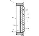
- FIG. 1 is a schematic cross-sectional view showing an example of an electrolytic cell in this embodiment.
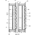
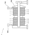
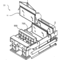
- FIG. 1B is an explanatory diagram when two electrolytic cells of FIG. 1A are connected in series. It is an explanatory view showing an example of an electrolytic cell in this embodiment. It is an explanatory view showing an example of a process of assembling an electrolytic cell in this embodiment.
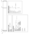
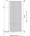
- 1 is an example of a block diagram showing a functional configuration of a device according to the present embodiment. It is a schematic diagram showing an example of electrolytic cell data concerning this embodiment. It is a schematic diagram showing an example of electrolytic cell data concerning this embodiment.
- FIG. 2 is a schematic diagram showing the amount of metal remaining in the electrodes for each electrolytic cell of an early bipolar electrolytic cell.
- FIG. 1 is a schematic cross-sectional view showing an example of an electrolytic cell in this embodiment.
- FIG. 1B is an explanatory diagram when two electrolytic cells of FIG. 1A are connected in series. It is an explanatory view showing an example
- FIG. 2 is a schematic diagram showing the amount of metal remaining in the electrodes for each electrolytic cell of a bipolar electrolytic cell in the middle stage. It is a schematic diagram showing the residual metal amount of the electrode for each electrolytic cell of the bipolar electrolytic cell of the latter stage.
- FIG. 2 is a schematic diagram showing the amount of metal remaining in the electrodes of each electrolytic cell of a bipolar electrolytic cell having a reverse current absorber and the like.
- FIG. 2 is a schematic diagram showing the amount of metal remaining in the electrodes of each electrolytic cell of a bipolar electrolytic cell when there is a reverse current. It is a schematic diagram showing an example of learning data concerning this embodiment. It is a schematic diagram showing an example of evaluation contents outputted by the device of this embodiment.
- FIG. 2 is a sequence diagram illustrating an example of a process executed by the apparatus according to the present embodiment.
- FIG. 1 is a schematic diagram showing an example of how the device according to the present embodiment is used.
- FIG. 1 is a schematic diagram showing an example of how the device according to the present embodiment is used.
- FIG. 1 is a schematic diagram showing an example of how the device according to the present embodiment is used.
- FIG. 1 is a schematic diagram showing an example of how the device according to the present embodiment is used.
- the present embodiment an embodiment of the present invention (hereinafter referred to as “the present embodiment") will be described in detail, but the present invention is not limited thereto, and various modifications can be made without departing from the gist thereof. It is.
- Electrolytic Cell FIG. 1A is a schematic cross-sectional view of an example of an electrolytic cell constituting the electrolytic cell of this embodiment.
- the electrolytic cell 90 includes an anode chamber 10, a cathode chamber 20, a partition wall 29 separating the anode chamber 10 and the cathode chamber 20, an anode 11 installed in the anode chamber 10, and a cathode 21 installed in the cathode chamber 20. , is provided.
- the anode 11 and cathode 21 belonging to one electrolytic cell 90 are electrically connected to each other.
- the cathode chamber 20 further includes a cathode 21 installed in the cathode chamber 20, a current collector 23, a support 24 that supports the current collector, and an elastic mat 1.
- the elastic mat 1 is placed between the current collector 23 and the cathode 21.
- the support body 24 is installed between the current collector 23 and the partition wall 29.
- the current collector 23 is electrically connected to the cathode 21 via the elastic mat 1.
- the partition 29 is electrically connected to the current collector 23 via the support 24 . Therefore, the partition 29, the support 24, the current collector 23, the elastic mat 1, and the cathode 21 are electrically connected.
- the cathode 21 and the reverse current absorber may be directly connected, or may be indirectly connected via a current collector, a support, a metal elastic body, a partition, or the like.
- the entire surface of the cathode 21 is coated with a catalyst layer for the reduction reaction.
- the form of electrical connection is such that the partition wall 29 and the support 24, the support 24 and the current collector 23, and the current collector 23 and the elastic mat 1 are directly attached, respectively, and the cathode 21 is laminated on the elastic mat 1. It may be a form. Methods for directly attaching these constituent members to each other include welding, the above-mentioned folding, and the like.
- each cathode 21 of a plurality of electrolytic cells 90 connected in series is pressed against the ion exchange membrane 2, and each anode 11 and each cathode are 21 becomes shorter, and the voltage applied to the entire plurality of electrolytic cells 90 connected in series can be lowered. By lowering the voltage, power consumption can be lowered.
- pressure can be applied to the ion exchange membrane with a moderate normal surface pressure, so a zero gap configuration can be achieved while maintaining current efficiency. , damage to the ion exchange membrane can also be preferably prevented.
- the cathode can be directly stacked on the elastic mat, or the cathode can be stacked with another conductive member interposed therebetween.
- a cathode that can be used for zero gap a cathode with a small wire diameter and a small mesh number is preferable because it has high flexibility.
- the wire constituting such a cathode is not particularly limited, but a wire with a wire diameter of 0.1 to 0.5 mm and an opening of about 20 mesh to 80 mesh can also be used.
- FIG. 1B is a cross-sectional view of two adjacent electrolytic cells 90 in the electrolytic bath 4 of this embodiment.
- FIG. 2A shows an electrolytic cell 30.
- FIG. 2B shows the process of assembling the electrolytic cell 30.
- the electrolytic cell 90, the ion exchange membrane 2, and the electrolytic cell 90 are arranged in series in this order.
- the ion exchange membrane 2 is arranged between the anode chamber of one electrolytic cell 90 and the cathode chamber of the other electrolytic cell 90 among two adjacent electrolytic cells in the electrolytic cell. That is, the anode chamber 10 of the electrolytic cell 90 and the cathode chamber 20 of the adjacent electrolytic cell 90 are separated by the ion exchange membrane 2.
- the electrolytic cell 30 is composed of a plurality of electrolytic cells 90 connected in series through the ion exchange membrane 2. That is, the electrolytic cell 30 is a bipolar electrolytic cell that includes a plurality of electrolytic cells 90 arranged in series and an ion exchange membrane 2 arranged between adjacent electrolytic cells 90. As shown in FIG. 2B, the electrolytic cell 30 is assembled by arranging a plurality of electrolytic cells 90 in series via the ion exchange membrane 2 and connecting them by a press 500.
- the electrolytic cell 30 has an anode terminal 700 and a cathode terminal 600 that are connected to a power source.
- the anode 11 of the electrolytic cell 90 located at the end of the plurality of electrolytic cells 90 connected in series in the electrolytic cell 30 is electrically connected to the anode terminal 700 .
- the cathode 21 of the electrolytic cell located at the opposite end of the anode terminal 700 is electrically connected to the cathode terminal 600 .
- Current during electrolysis flows from the anode terminal 700 side toward the cathode terminal 600 via the anode and cathode of each electrolysis cell 90.
- an electrolytic cell having only an anode chamber (anode terminal cell) and an electrolytic cell having only a cathode chamber (cathode terminal cell) may be arranged at both ends of the connected electrolytic cells 90.
- the anode terminal 700 is connected to the anode terminal cell arranged at one end
- the cathode terminal 600 is connected to the cathode terminal cell arranged at the other end.
- salt water is supplied to each anode chamber 10, and pure water or a low concentration aqueous sodium hydroxide solution is supplied to the cathode chamber 20.
- Each liquid is supplied to each electrolytic cell 90 from an electrolyte supply pipe (not shown) via an electrolyte supply hose (not shown). Further, the electrolytic solution and the products of electrolysis are recovered from an electrolytic solution recovery pipe (not shown).
- sodium ions in salt water move from the anode chamber 10 of one electrolytic cell 90 to the cathode chamber 20 of the adjacent electrolytic cell 90 through the ion exchange membrane 2 . Therefore, the current during electrolysis flows along the direction in which the electrolytic cells 90 are connected in series.
- the current flows from the anode chamber 10 to the cathode chamber 20 via the ion exchange membrane 2.
- chlorine gas is generated on the anode 11 side
- sodium hydroxide (solute) and hydrogen gas are generated on the cathode 21 side.
- alkaline water electrolysis There are two types of alkaline water electrolysis: one that uses a cation exchange membrane and one that uses an anion exchange membrane.
- alkali metal ions K + and Na +
- hydroxide ions OH -
- the remaining amount of noble metal coating on the electrodes of the electrolytic cell gradually decreases as the electrolytic apparatus operates.
- the degree of reduction is affected by operating conditions such as operating time and operating voltage, and operating problems such as occurrence of reverse current.
- operating conditions such as operating time and operating voltage, and operating problems such as occurrence of reverse current.
- the magnitude of the reverse current generated varies depending on the position of the electrolytic cell in the electrolytic cell, so the electrolytic cell in the electrolytic cell.
- the degree of reduction in the remaining amount of precious metal coating also differs depending on the position.
- the device of this embodiment includes a management unit that records usage history information of electrodes included in the electrolytic cell based on operation history information of an electrolytic cell including one or more electrolytic cells.
- the history of the electrolytic cell is referred to as "operation history” and the history of the electrodes is referred to as "usage history.”
- This "usage history” is used to refer to all the history that the electrode has undergone, and includes information based on the past operation history of the electrolytic cell, as well as repair history. Further, the usage history may also include a history of reusing an electrode of one electrolytic cell as an electrode of a different electrolytic cell.
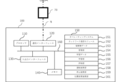
- the device 100 may be a device connected to the electrolysis device 10 via a wired or wireless network N, or the device 100 and the electrolysis device 10 may be connected together. It may be configured as one device. Further, the device 100 may have a configuration in which at least part of the processing of the functional unit shown in FIG. 3 is performed by another device such as a server connected through the network N.
- Device 100 includes, for example, a processor 110, a communications interface 120, an input/output interface 130, memory 140, storage 150, and one or more communications buses 160 for interconnecting these components.
- the processor 110 executes processes, functions, or methods implemented by codes or instructions included in programs stored in the storage 150.
- Processor 110 may include, by way of example and not limitation, one or more central processing units (CPUs), MPUs (Micro Processing Units), GPUs (Graphics Processing Units), microprocessors, processor cores, multiprocessors.
- Logic circuits hardware formed on integrated circuits (IC (Integrated Circuit) chips, LSI (Large Scale Integration)), etc.
- IC Integrated Circuit
- LSI Large Scale Integration
- the communication interface 120 sends and receives various data to and from other devices via the network.
- the communication may be performed by wire or wirelessly, and any communication protocol may be used as long as mutual communication can be performed.
- the communication interface 120 is implemented as hardware such as a network adapter, various communication software, or a combination thereof.
- Networks include, by way of example and not limitation, an ad hoc network, an intranet, an extranet, a virtual private network (VPN), a local area network (LAN), or a wireless LAN.
- VPN virtual private network
- LAN local area network
- LAN wireless LAN
- WLAN Wireless LAN: WLAN
- Wide Area Network WAN
- WWAN Wireless WAN
- Metropolitan Area Network MAN
- PSTN Public Switched Telephone Network Telephone Network
- PSTN Public Switched Telephone Network Telephone Network
- PSTN Public Switched Telephone Network Telephone Network
- PSTN Public Switched Telephone Network Telephone Network
- PSTN Public Switched Telephone Network Telephone Network
- PSTN Public Switched Telephone Network Telephone Network
- PSTN Public Switched Telephone Network Telephone Network
- PSTN Public Switched Telephone Network Telephone Network
- PSTN Public Switched Telephone Network Telephone Network
- PSTN Public Switched Telephone Network Telephone Network
- PSTN Public Switched Telephone Network Telephone Network
- PSTN Public Switched Telephone Network Telephone Network
- PSTN Public Switched Telephone
- the input/output interface 130 includes an input device for inputting various operations to the device 100, and an output device for outputting processing results processed by the device 100.
- the input/output interface 130 includes information input devices such as a keyboard, mouse, and touch panel, and information output devices such as a display.
- the device 100 may receive a predetermined input by connecting an external input/output interface 130.
- the device 100 is connected to an X-ray fluorescence spectrometer, an inductively coupled plasma emission spectrometer, an X-ray diffraction device, or an X-ray photoelectron spectrometer as an external input/output interface 130 via a priority or wireless network N. may have been done.
- an X-ray fluorescence spectrometer an inductively coupled plasma emission spectrometer, an X-ray diffraction device, or an X-ray photoelectron spectrometer as an external input/output interface 130 via a priority or wireless network N.
- the memory 140 temporarily stores programs loaded from the storage 150 and provides a work area for the processor 110.
- the memory 140 also temporarily stores various data generated while the processor 110 is executing a program.
- Memory 140 may be, for example, a high speed random access memory such as DRAM, SRAM, DDR RAM or other random access solid state storage, or a combination thereof.
- Storage 150 stores programs, each functional unit, and various data.
- Storage 150 may be, for example, non-volatile memory such as one or more magnetic disk storage devices, optical disk storage devices, flash memory devices, or other non-volatile solid state storage devices, or a combination thereof.
- Other examples of storage 150 may include one or more storage devices located remotely from processor 110.
- storage 150 stores programs, functions and data structures, or a subset thereof.
- the device 100 has a management section 154, a learning section 156, an evaluation section 157, a driving suggestion section 158, and a stoppage section, as shown in FIG. It is configured to function as a proposal unit 159 and a position change proposal unit 161.
- Operating system 151 includes, for example, procedures for handling various basic system services and performing tasks using hardware.
- Network communication unit 152 may, for example, communicate device 100 to other computers via communication interface 120 and one or more communication networks, such as the Internet, other wide area networks, local area networks, metropolitan area networks, etc. used to connect.
- communication networks such as the Internet, other wide area networks, local area networks, metropolitan area networks, etc. used to connect.
- Electrolytic cell data 153 may store information regarding the electrolytic cell 30 and operation history information of the electrolytic cell 30 for each electrolytic cell. Electrolytic cell data 153 stored in storage 150 will be described with reference to FIGS. 4A and 4B.
- Information regarding the electrolytic cell 30 is not particularly limited, and includes, for example, the number of electrolytic cells 31 that the electrolytic cell 30 has, the device configuration of the electrolytic device 10, and the like.
- the usage history information of the electrode is not particularly limited, but includes, for example, initial data on the types of metals the electrode has and the amount of metals supported before operation, and measurements of the types of metals the electrode has and the amount of metals supported during operation. Examples include actual measurement data, repair history, information based on electrolytic cell operation history information, and evaluation values.
- the initial data may be, for example, information obtained from an electrode manufacturer.
- the actual measurement data may be data acquired from the input/output interface 130 of a fluorescent X-ray analyzer or the like, such as fluorescent X-ray analysis data, inductively coupled plasma emission analysis data, and X-ray diffraction data of the electrodes of the electrolytic cell. , or may include X-ray photoelectron spectroscopy data.
- the method for quantifying precious metals from these analysis data is not particularly limited as long as it is a conventionally known method, but for example, by using a calibration curve from fluorescent X-ray analysis data, it is possible to determine the amount of each precious metal in the catalyst layer of the electrode.
- Examples include a method of calculating the remaining amount of coating, and a method of calculating the remaining amount of coating of each noble metal in the catalyst layer of the electrode from the strength ratio of the metal used in the base material of the electrode and each noble metal contained in the catalyst layer.
- the initial data and actual measurement data may be stored for each electrolytic cell 31.
- the initial data and actual measurement data do not need to include initial data and actual measurement data regarding all the electrolytic cells 31-1 to 31-N included in the electrolytic cell 30, but regarding some of the electrolytic cells 31-N.
- the information may include initial data and measured data.
- the measured data of FIG. 4A the measured data for all electrolytic cells 31-1 to 31-100 are not measured, and the measured data for cells 31-1, 31-50, and 31-100 are not measured.
- An example in which actual measurement data is measured and stored is shown.
- the electrolytic cell 30 is a bipolar type
- information regarding the position of each electrolytic cell in the electrolytic cell 30 may be included.
- Information regarding the position of each electrolytic cell in the electrolytic cell 30 is not particularly limited, but may be, for example, the position of the electrolytic cell counted from the end, such as the first, second, etc. from the end. .
- the actual measurement data is written as 31-1 cell, 31-50 cell, and 31-100 cell, so that the position of each electrolytic cell in the electrolytic cell 30 is memorized. Good too. Thereby, the state of the electrolytic cell 31-N according to the position in the electrolytic cell 30 can be specifically stored.
- the timing and contents of replacement or repair of the electrolytic cell may be stored for each electrolytic cell.
- the information based on the operation history information of the electrolytic cell included in the electrode usage history information includes the total operating time of the electrolytic cell, the total amount of current, and other information described in the operation history information of the electrolytic cell described later. Good too.
- the evaluation values include, for example, a metal amount evaluation value that evaluates the catalytic ability, such as the amount of metal in the catalyst layer of the electrode, and an impurity evaluation value that shows the extent to which the catalytic ability is inhibited, such as the amount of impurities attached to the electrode. etc. may be included.
- the metal content evaluation value is also referred to as the remaining precious metal coating amount.
- the metal content evaluation value it is possible to evaluate whether the catalytic ability of the electrode has decreased due to a decrease in the metal content
- the impurity evaluation value it is possible to evaluate whether the electrode has deteriorated due to the adhesion of impurities. It is possible to evaluate whether or not the ability is decreasing.
- the metal content evaluation value of a certain electrode is high and the impurity evaluation value is low, this means that the metal content of that electrode is maintained, but sufficient performance cannot be achieved due to the adhesion of impurities. It can be evaluated as follows. Through this kind of evaluation, it is possible to decide whether to extend the life of the electrode by increasing its metal content or by removing impurities. You can make better point judgments.
- the metal content evaluation value of a certain electrode is low, whether the degree of decrease in metal content is within a range that can be recovered with simple treatment or whether it can be recovered with fundamental treatment. It is also possible to evaluate the extent of the problem. By performing this kind of evaluation, it is possible to determine which treatment is appropriate among multiple types of treatment when extending the life of an electrode by increasing its metal content. It is possible to make a more appropriate judgment in this regard.
- the operation history information of the electrolytic cell included in the electrolytic cell data 153 is not particularly limited, but includes, for example, the total operating time of the electrolytic cell, the total amount of current supplied, the current density, the operating voltage, the current efficiency, the operating temperature, the electrolyte, and the anode.
- the flow rate of the electrolytic solution supplied to the chamber and the cathode chamber, information regarding reverse current, the number of stops, etc., and other known conditions to be controlled or observed in the operation of the electrolyzer 10 may be mentioned.
- gas purity refers to the purity of gas generated at the cathode or anode.
- the operation history information of the electrolytic cell 30 may be recorded over time. As shown in FIG. 4B, current density, operating voltage, operating temperature, and other conditions that may change over time can be stored as information over time. It has been found that the remaining amount of noble metal coating on the electrode gradually decreases even when the electrolyzer 10 is operating normally. Therefore, by recording driving history information as time-dependent information in this way, the metal content evaluation value of the electrode may be estimated more specifically.
- the impurity evaluation value of the electrode may be estimated more specifically by recording driving history information.
- such data on the operating history over time may include evidence of stoppage periods and reverse current.
- reverse current will be explained.
- the electrolysis cell 31 can cause a self-discharge reaction through a leakage current circuit formed by the electrolyte supply piping when electrolysis is stopped.
- the self-discharge reaction is called a reverse current because the direction of the current flowing through the current-carrying surface is opposite to that during electrolysis.
- the electrode of the electrolytic cell 31 is oxidized and reduced in the process of generating a reverse current, and the catalyst layer on the surface of the base material may fall off, which may severely affect the amount of precious metal coating remaining.
- the negative electrode 35 tends to be more affected by the reduction in the amount of noble metal coating remaining due to such reverse current.
- a reverse current may also occur when the current density is extremely reduced. Specifically, when a positive electrolytic current and a reverse current are compared and the reverse current is larger, a reverse current may occur. Data on driving history over time may include evidence of such reverse current.
- the information regarding the electrolytic solution in the operation history information of the electrolytic cell 30 may include information regarding the type and amount of impurities in addition to the composition of the electrolytic solution. If the electrolyte contains impurities, the impurities may adhere to the electrodes. Impurities adhering to the electrodes affect the operation of the electrolyzer 10 and also affect the amount of precious metal coating remaining on the electrodes. Therefore, by recording information regarding the electrolytic solution as driving history information in this way, the behavior of decreasing the amount of noble metal coating remaining on the electrode may be estimated more specifically. In particular, the influence of the reduction in the remaining amount of precious metal coating due to such impurities tends to be greater on the anode 33.
- the management unit 154 records usage history information of the electrodes included in the electrolytic cell based on the operation history information of the electrolytic cell. More specifically, the management unit 154 acquires operational history information of the electrolytic cell from the control unit 70 of the electrolyzer 10, records the acquired operational history information in electrolytic cell data, and records the recorded operational history information. Based on this, recording of usage history information of electrodes included in the electrolytic cell may be performed. Note that the destination from which the management unit 154 of the device 100 acquires the operation history information of the electrolytic cell is not limited to the control unit 70 of the electrolytic device 10.
- the management unit 154 may further record the metal content evaluation value of the electrode and the impurity evaluation value of the electrode as usage history information.
- the metal content evaluation value is not particularly limited as long as it is a value indicating catalytic ability such as the metal content of the catalyst layer of the electrode, and may be the remaining amount of precious metal coating.
- the impurity evaluation value is not particularly limited as long as it is a value indicating the extent to which the performance of the catalyst is inhibited, such as the amount of impurities attached to the electrode, and may be the amount of impurities attached.
- the management unit 154 may record actual measurement data of the remaining amount of precious metal coating as the metal content evaluation value, or may record at least one of initial data, actual measurement data, repair history, and operation history information of the electrolytic cell. Based on this, the metal content evaluation value may be calculated and recorded.
- the metal content evaluation value may be calculated and recorded.
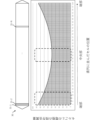
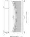
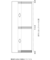
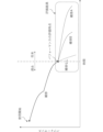
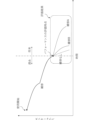
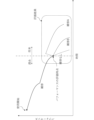
- FIG. 5A to 5E show the amount of remaining metal in the electrodes for each electrolytic cell of a bipolar electrolytic cell, with the vertical axis showing the remaining amount of metal and the horizontal axis showing the amount of metal remaining in the electrode in the bipolar electrolytic cell.
- FIG. 5A is a graph showing the amount of remaining metal in the unused electrode before operation as 100%
- FIG. 5B is a graph showing the amount of remaining metal in the electrode after operating the electrolyzer 10 for a predetermined time
- 5C is a graph showing the amount of metal remaining in the electrode after the electrolyzer 10 is further operated from the state shown in FIG. 5B.
- the remaining amount of precious metal coating tends to gradually decrease as the electrolytic device 10 operates. Therefore, it is possible to estimate the remaining amount of noble metal coating on the electrode based on operation history information such as how long the device was operated and under what conditions (voltage, current, etc.).
- FIGS. 5A to 5C it has been found that in the case of a bipolar electrolytic cell, the degree of reduction in the remaining amount of noble metal coating varies depending on the position of the electrolytic cell. More specifically, it has been found that the electrolytic cell located in the center of a bipolar electrolytic cell tends to have a smaller amount of precious metal coating remaining. This is because when the electrolyzer 10 is repeatedly operated and stopped, reverse current is more likely to occur in the electrolytic cell located in the center.
- the evaluation is performed by weighting the degree of decrease in the remaining amount of precious metal coating according to the cell position. You may do so. More specifically, the remaining amount of noble metal coating may be evaluated by adjusting the electrolytic cell located in the center of the bipolar electrolytic cell so that the degree of decrease in the remaining amount of noble metal coating becomes greater. This makes it possible to collectively estimate the amount of noble metal coating remaining on the electrodes of the electrolytic cells even in the case of having a large number of electrolytic cells such as a bipolar electrolytic cell.
- the electrolytic cell has a reverse current absorber or the electrode has a reverse current absorbing layer
- the electrolytic cell located in the center of the bipolar electrolytic cell and the electrolytic cell located at the end The amount of precious metal coating remaining may be more relaxed (FIG. 5D).
- the repair history includes repainting the catalyst layer on the electrode of the electrolytic cell, or replacing the electrode or the electrolytic cell itself, the time when the electrolytic cell was repaired or replaced should be noted.
- the degree of decrease in the remaining amount of precious metal coating from that point may be calculated by setting it as 100%. Thereby, the remaining amount of precious metal coating can be individually evaluated even for electrolytic cells that have a history of repair.
- the calculation process of the metal content evaluation value executed by the management unit 154 is not particularly limited, but for example, a formula for calculating the metal content evaluation value of the electrode is calculated using values included in the driving history information as variables. Examples of methods used include: More specifically, the formula for calculating the metal content evaluation value includes values that indicate the total amount of operation such as total operating time and total energization amount, and steady state values such as operating voltage, operating temperature, current density, and type of electrolyte. One example is one in which variables are values indicating operating conditions.
- Such a formula is generated by machine learning processing based on learning data that includes information on the operating history and information on the metal content evaluation value of the electrodes of each electrolytic cell of the bipolar electrolytic cell that has undergone the operating history. It may also be obtained as a trained model.
- the management unit 154 performs machine learning processing based on learning data including information regarding the operation history and information regarding the metal content evaluation value of the electrodes of each electrolytic cell of the bipolar electrolytic cell that has undergone the operation history.
- the metal content evaluation value may be predicted using the trained model generated by . Note that generation of learning data and trained models will be described later.
- the management unit 154 determines the metal content evaluation values of the electrodes of other electrolytic cells based on the operation history information of the electrolytic cell and the data obtained by actually measuring the metal content evaluation values of the electrodes of some electrolytic cells. may be predicted.
- the metal content evaluation value varies from the edge to the center.
- the weight of the degree of decrease in the metal content evaluation value depending on the position of the cell may be adjusted based on the estimated phenomenon curve.
- the phenomenon curve refers to a curve that shows a tendency for the metal content evaluation value to increase as it approaches the edges and decrease as it approaches the center, as shown in FIGS. 5B and 5C. .
- the electrolytic cells located at the ends and the center of the bipolar electrolytic cell are surrounded by a square with a broken line as the electrolytic cells from which the actual measured data is obtained, and the actual measured data considered by the management unit 154 is It shows that it includes actual measurement data of the metal content evaluation values of the electrodes of the electrolytic cells located at the ends and center of the electrolytic cell.
- the reduction curve is not limited to this but can be estimated if there is actual measurement data of at least two arbitrary electrolytic cells. More specifically, if it is known in advance that a reduction curve can be obtained, and if there is actual measurement data for electrolytic cells at two arbitrary locations, the metal content evaluation value actually measured by the electrolytic cells at those two locations can be calculated. It is possible to fit a decreasing curve that satisfies Further, in FIG. 5B, a plurality of electrolytic cells are collectively surrounded by a rectangle with a broken line, but the present invention is not limited to this, and as long as there is actually measured data of at least one electrolytic cell at two locations, the reduction curve can be fitted.
- the actual measurement data may include fluorescent X-ray analysis data, inductively coupled plasma emission analysis data, X-ray diffraction data, or X-ray photoelectron spectroscopy data of the electrodes included in the electrolytic cell.
- the actual measurement data may be data acquired from the input/output interface 130 of a fluorescent X-ray analyzer or the like, and may include fluorescent X-ray analysis data, inductively coupled plasma emission analysis data, and X-ray diffraction data of the electrodes of the electrolytic cell. , or may include X-ray photoelectron spectroscopy data.
- the management unit 154 may predict the metal content evaluation value of the cathode based on operation history information including information regarding reverse current. This makes it possible to predict the metal content evaluation value in consideration of the decrease in the metal content evaluation value at the cathode due to the occurrence of a reverse current as shown in FIG. 5E.
- the management unit 154 may predict the metal content evaluation value of the anode based on operation history information including information regarding impurities in the electrolytic solution. If the electrolyte contains impurities, the impurities may adhere to the electrodes. Impurities adhering to the electrodes affect the operation of the electrolyzer 10 and also affect the amount of precious metal coating remaining on the electrodes. In particular, the anode 33 tends to be more affected by the reduction in the amount of noble metal coating remaining due to such reverse current. Therefore, by recording information regarding the electrolyte as driving history information in this way, it becomes possible to predict the metal content evaluation value of the electrode.
- the management unit 154 may predict the metal content evaluation value for each of the anode and cathode. As mentioned above, although the decreasing trends in the metal content evaluation values may not match for the anode and cathode, it is possible to more appropriately estimate the precious metal content by predicting the metal content evaluation values for the anode and cathode respectively. Can be done.
- the metal content evaluation value predicted by the management unit 154 may include the remaining coating amount of a noble metal selected from the group consisting of ruthenium, rhodium, palladium, osmium, iridium, and platinum. Since these metals function as the main active species in the catalyst layer of the electrode, it is useful to non-invasively evaluate the remaining amount of these rare metals.
- a noble metal selected from the group consisting of ruthenium, rhodium, palladium, osmium, iridium, and platinum. Since these metals function as the main active species in the catalyst layer of the electrode, it is useful to non-invasively evaluate the remaining amount of these rare metals.
- the calculation process of the impurity evaluation value executed by the management unit 154 is not particularly limited, but for example, a method using a formula for calculating the impurity evaluation value of the electrode using values included in the driving history information as variables is a method.
- the formula for calculating the impurity evaluation value includes values that indicate the total amount of operation, such as total operating time and total energization amount, as well as values that indicate the amount of impurity during operation, such as the type of electrolyte and the type and amount of impurities contained in it.
- the impurity evaluation value may include indicators such as the surface coverage of the electrode by impurities and the thickness of impurity adhesion.
- Such a formula was generated by machine learning processing based on learning data including information on the operating history and information on the impurity evaluation value of the electrodes of each electrolytic cell of the bipolar electrolytic cell that has undergone the operating history. It may also be obtained as a trained model.
- the management unit 154 performs machine learning processing based on learning data including information regarding the operation history and information regarding the impurity evaluation value of the electrodes of each electrolytic cell of the bipolar electrolyzer that has undergone the operation history.
- the impurity evaluation value may be predicted using the generated trained model. Note that generation of learning data and trained models will be described later.
- the evaluation unit 157 may evaluate the future performance of the electrode based on the usage history information of the electrode. Furthermore, the evaluation unit 157 may evaluate the future performance of the repaired electrode based on the usage history information of the electrode and the planned repair method.
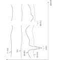
- FIGS. 7A to 7D are schematic diagrams showing examples of evaluation contents output by the evaluation unit 157.
- the performance of the electrode from the start of use is shown by a solid line
- the future performance of the electrode evaluated by the evaluation unit 157 is shown by a broken line.
- the solid lines in FIGS. 7A to 7D show that the performance of the electrode gradually deteriorates as time passes from the start of use, and that the rate of deterioration of the electrode's performance slows down by undergoing prescribed repairs midway through use. It is shown that.
- the performance of the electrode may be the efficiency of electrolytic reaction, or a value related to the metal content evaluation value or the impurity evaluation value.
- FIGS. 7A to 7D indicate the future performance of the electrode evaluated by the evaluation unit 157 in the case of no repair, the case of repair A, and the case of repair B.
- repair or non-repair can make a difference in the future performance of the electrode.
- the future performance of the electrode may differ depending on the nature of the repair.
- FIG. 7B depending on the usage history information, an evaluation result in which there is no difference in effectiveness between repair A and repair B, which had a difference in effectiveness in FIG. 7A, is assumed.
- FIG. 7C depending on the usage history information, an evaluation result may be assumed in which the effect of repair B, which had a difference in effect in FIG. 7A, is no longer different from that of the case without repair.
- the effect of repair is not limited to extending the life of the electrode performance as shown in FIGS. 7A to 7C, but may have the effect of temporarily improving performance as shown in FIG. 7D.
- repair A and repair B may have different effects on future performance, or the difference in effectiveness may decrease between no repair and repair. Conditions such as this may occur. For example, if the metal content evaluation value of a certain electrode is high and the impurity evaluation value is low, this means that the metal content of that electrode is maintained, but sufficient performance cannot be achieved due to the adhesion of impurities. It can be evaluated as follows. By doing so, it is possible to grasp the situation where repair A, which removes impurities, has a certain effect, but repair A, which increases the amount of metal, is less effective, and to select a more appropriate repair content. Or, is the degree of decrease in metal content within a range that can be recovered with simple treatment (repair B) or is it within a range that can be recovered with fundamental treatment (repair A)? You can also evaluate points.
- the evaluation unit 157 evaluates the magnitude of the metal content evaluation value and the impurity evaluation value based on one of the metal content evaluation value and the impurity evaluation value, and based on the evaluation result, determines whether the performance can be extended most or temporarily.
- the repair details that can be improved the most can be output and displayed on a display.
- information regarding the future performance of the electrode based on each repair content can also be presented and displayed on a display or the like.
- the evaluation of the magnitude of the metal content evaluation value and the impurity evaluation value refers to evaluating the magnitude of the metal content and impurity content by comparing them. For example, when the metal content evaluation value is large and the impurity evaluation value is small, the evaluation unit 157 may specify and output the repair content that reduces the impurity content. Further, when the metal content evaluation value is small and the impurity evaluation value is small, the evaluation unit 157 may specify and output the repair content that increases the metal content.
- the evaluation unit 157 may output the repair content that can most prolong the life or most temporarily improve the performance based on the impurity evaluation value, and display it on a display or the like. Similarly, information regarding the future performance of the electrode based on each repair content can also be presented and displayed on a display or the like.
- the model learning unit 156 uses the learning data 155 for learning the machine based on the learning data 155 including information regarding the operation history and information regarding the metal content evaluation value or impurity evaluation value of the electrode of each electrolytic cell of the electrolytic cell that has undergone the operation history.
- a trained model may be obtained by performing a learning process.
- the learned model obtained in this way becomes a model used by the management unit 154, and inputs information regarding the operation history, and evaluates the metal content or impurity of the electrodes of each electrolytic cell of the electrolytic tank that has undergone the operation history.
- the output may be information regarding the value.
- the learning data 155 may store, for example, information regarding the electrolytic cell 30, operation history information of the electrolytic cell 30, and information regarding the metal content evaluation value or impurity evaluation value of the electrolytic cell 30 for each electrolytic cell.
- the learning data 155 stored in the storage 150 will be explained with reference to FIG. 6.
- the information regarding the electrolytic cell 30 and the operation history information of the electrolytic cell 30 stored in the learning data 155 can be the same as that described in the electrolytic cell data 153.
- information regarding the metal content evaluation value or impurity evaluation value of the electrolytic cell 30 can be stored. More specifically, as shown in FIG. 6, information that summarizes measured data of metal content evaluation values or impurity evaluation values for each electrolytic cell may be mentioned.
- the learning unit 156 uses information regarding the operation history and information regarding the remaining amount of precious metal coating on the electrodes of each electrolytic cell of the electrolytic cell that has undergone the operation history as learning data, and uses information regarding the remaining amount of precious metal coating as a correct label.
- a model may be constructed using machine learning.
- the learning unit 156 may configure models other than machine learning models.
- models include, for example, values that indicate the total amount of operation, such as total operating time and total energization amount, and values that indicate conditions during steady operation, such as operating voltage, operating temperature, current density, and type of electrolyte. Examples include variables. The coefficients of such variables may be determined based on the learning data 155.
- the learning unit 156 may perform machine learning processing to obtain a learned model based on the learning data 155 including electrode usage history information and information regarding electrode performance.
- the trained model obtained in this way becomes a model used by the evaluation unit 157, which inputs information regarding the operation history and outputs information regarding the future performance of the electrodes of each electrolytic cell of the electrolytic cell that has undergone the operation history. It is also possible to do so.
- the electrode usage history information in the learning data 155 includes a repair history
- information regarding the future performance of the electrode after repair is output based on the electrode usage history information and the repair method. It is also possible to obtain a trained model.
- the operation proposal unit 158 may propose operating conditions for the electrolytic cell 30. Specifically, the driving proposal unit 158 can propose driving conditions for increasing current efficiency based on usage history information.
- the electrolytic cell 30 In the electrolytic cell 30, movement of ions in the electrolytic solution, transfer of electrons on the electrode surface, and generation of substances accompanying this occur.
- the substance involved in this electrolytic reaction is not limited to the target substance. Therefore, it is desirable to increase the current efficiency with respect to the target substance.
- the "current efficiency" in the electrolytic cell 30 refers to the ratio of the amount of material actually produced to the theoretical maximum amount of material produced by a certain amount of electricity in the electrolytic cell.
- the target substances are, for example, chlorine gas and hydrogen gas in the case of salt water electrolysis, and oxygen gas and hydrogen gas in the case of alkaline water electrolysis.
- High current efficiency means that much of the electricity used is used to generate the desired substance, such as hydrogen gas.
- the operating conditions of the electrolytic cell 30 be such that the desired electrolytic reaction is carried out with as high a current efficiency as possible.
- the operation proposal unit 158 proposes operation conditions including voltage conditions and electrolyte flow conditions based on usage history information. Good too. Note that the operating conditions are not limited to these, and may include other conditions such as the concentration of the electrolytic solution and temperature conditions.
- the usage history information may include a metal content evaluation value. At this time, the usage history information becomes information that reflects the amount of active species in the electrode. Further, the voltage condition is a value that controls the amount of current flowing between the electrodes. Further, the flow rate condition of the electrolytic solution is a value that controls the amount of ions that exchange electrons with the electrode and the contact efficiency between the electrolytic solution and the electrode. Suitable values for other operating conditions may vary if the amount of active species in the electrode differs. That is, based on the metal content evaluation value, the operation proposal unit 158 selects voltage conditions and conditions under which the movement of ions in the electrolytic solution and the transfer of electrons on the electrode surface proceed more appropriately and the current efficiency is increased. The electrolyte flow rate conditions can be proposed as at least operating conditions.
- the electrolytic cell 30 can be operated under operating conditions in which the current efficiency increases according to fluctuations in the metal content evaluation value.
- the current efficiency of the electrolytic cell 30 can be maintained high from a long-term perspective, and the yield can be further increased. Can be done.
- repair factors refer to factors that do not require immediate repair but may lead to performance deterioration, such as deterioration of partition walls or a decrease in metal content evaluation value.
- the electrolytic cell 30 is a huge device and requires time to stop for repairs and restart operation, so in order to maximize the operating efficiency of the electrolytic cell 30, it is better to stop the electrolytic cell 30 less frequently. Also from the viewpoint of the influence of the reverse current on the metal content evaluation value, the fewer the number of stops, the better.
- the stop suggestion unit 159 may propose a stop condition for the electrolytic cell 30. Specifically, the stop suggestion unit 159 can propose a stop condition under which the amount of metal in the electrode is unlikely to decrease, based on the usage history information.
- the electrode of the electrolytic cell 31 is oxidized and reduced during the process of generating a reverse current, causing the catalyst layer on the surface of the base material to fall off and the amount of metal in the electrode to be extremely affected. There are cases.
- the reverse current is due to a self-discharge reaction through the leakage current circuit formed by the electrolyte supply piping when electrolysis is stopped.
- the stop proposal unit 159 does not suddenly reduce the voltage applied to the electrolytic cell 30 to 0V, but gradually reduces the voltage to gradually attenuate the current flowing through the electrolytic cell 30 and then , a current attenuation condition in which the voltage applied to the electrolytic cell 30 is 0V may be proposed as the stop condition.
- a current attenuation condition in which the voltage applied to the electrolytic cell 30 is 0V may be proposed as the stop condition.
- the stop proposal unit 159 provides the anode chamber 10 and the cathode chamber 10 in order to quickly expel generated gas such as chlorine gas involved in the reaction of the reverse current from the anode chamber 10 and the cathode chamber 20.
- a condition for increasing the flow rate of the electrolytic solution supplied to the chamber 20 may be proposed as a stopping condition. The higher the flow rate of the electrolyte supplied to the anode chamber 10 and the cathode chamber 20, the further downstream the generated gas generated at the electrodes will be. Thereby, reverse current can be suppressed compared to the case where the voltage is set to 0V in a state where more produced gas is mixed in the electrolytic solution in the anode chamber 10 and the cathode chamber 20.
- the stop proposal unit 159 can propose conditions for attenuation of the current and conditions for increasing the flow rate of the electrolytic solution based on usage history information such as the metal content evaluation value. Specifically, in consideration of the fact that reverse current is more likely to occur in the central portion and the amount of metal in the electrode is small, the stop proposal unit 159 sets the current attenuation condition in accordance with the portion where the amount of metal in the electrode is small. You may. Similarly, in consideration of the fact that reverse current is more likely to occur in the central portion, the stop proposal unit 159 increases the flow rate of the electrolyte to match the portion where the metal content of the electrode is small. Conditions may be set.
- the stop proposal unit 159 can estimate a portion where a reverse current is likely to occur based on the distribution of the amount of metal in the electrode.
- the operation of the electrolytic cell 30 can be stopped under stop conditions that make it more difficult for reverse current to occur.
- the control section 70 of the electrolytic cell 30 adopts the stop conditions proposed by the stop proposal section 159, so that the current efficiency of the electrolytic cell 30 can be maintained high from a long-term perspective, and the yield can be further increased. Can be done.
- the suppression of reverse current achieved by the stoppage proposal unit 159 is also related to extending the life of the electrolytic cell 30.
- the electrolytic cell 30 is a huge device, and as shown in FIGS. 5A to 5C, in the case of a bipolar electrolytic cell, the degree of reduction in the amount of metal in the electrodes varies depending on the position of the electrolytic cell 90. Easy to occur. Although such a difference in the amount of metal in the electrodes can be tolerated to some extent, if the difference becomes large and the amount of metal in the electrodes of some electrolytic cells 90 becomes smaller than a predetermined value, the operation will be stopped, Repairs to that part will be required.
- the electrode metal content of other electrolytic cells 90 has also become considerably smaller. Due to the condition, it may be necessary to immediately stop operation and carry out repairs. If such repetition occurs, the number of stops will increase, so it is preferable that the difference in the degree of reduction in the amount of metal in the electrode depending on the position of the electrolytic cell be small.
- the suppression of reverse current achieved by the stop suggestion unit 159 makes the degree of decrease in the amount of metal in the electrodes more uniform depending on the position of the electrolytic cell 90, and avoids the situation where only some electrodes are repaired. This contributes to extending the life of the electrolytic cell 30 during operation.
- the stoppage proposal unit 159 may propose a stop condition based on the difference in the configuration of the electrolytic cell 30. It is assumed that the electrolytic cells 30 are different in scale, electrical system specifications, electrolyte feeding specifications, and the like. Therefore, the stop proposal unit 159 can suppress the reverse current more effectively by proposing stop conditions that take these into consideration.
- the position change proposal unit 161 selects electrolytic cells 90 with a relatively high remaining amount of precious metal coating and electrolytic cells 90 with a relatively high remaining amount of precious metal coating, based on usage history information. It may be proposed to change the position of the electrolytic cell 90, which has a relatively low value, in the electrolytic bath.
- the usage history information of the electrolytic cell 90 may vary depending on the location.
- the usage history information of the electrolytic cell 90 may vary depending on the location.
- other electrolytic cells 90 will also have a metal content. Since the evaluation value has become considerably small or the impurity evaluation value has become considerably large, it may be necessary to immediately stop operation and perform repairs.
- the electrolytic cell 90 with a relatively high metal content evaluation value or a relatively low impurity evaluation value will be referred to as a "first cell.” Further, the electrolytic cell 90 having a relatively low metal content evaluation value or a relatively high impurity evaluation value will be hereinafter referred to as a "second cell”.
- the first cell is placed at a position where the amount of metal tends to decrease or the amount of impurities tends to increase
- the second cell is placed at a position where the amount of metal tends to increase. It is placed at a position where the amount of impurities is difficult to decrease or increase. If the system is restarted with this arrangement, the difference in metal content and impurity content between the first cell and the second cell can be resolved.
- the position change proposal unit 161 proposes a combination of the first cell and the second cell to be replaced based on the usage history information indicating the degree of reduction, that is, the amount of metal and impurity, so that the entire electrolytic cell 30 can be replaced. As a result, it is possible to eliminate differences in the amounts of metals and impurities and keep the amounts of metals and impurities more uniform.
- the position change proposal unit 161 avoids the situation where only some electrodes are repaired and extends the length of the electrolytic cell 30, as described in the stop proposal unit 159. Contributes to longer service life and operation.
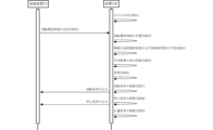
- FIG. 8 is a sequence diagram illustrating an example of processing executed by the apparatus according to this embodiment.
- step S801 the learning unit 156 of the device 100 generates learning data including information regarding the operation history and information regarding the metal content evaluation value or impurity evaluation value of the electrodes possessed by each electrolytic cell of the electrolytic cell that has undergone the operation history.
- a machine learning process may be performed to obtain a trained model.
- the model can be used by the management unit 154 when calculating the metal content evaluation value or the impurity evaluation value.
- step S801 the learning unit 156 of the device 100 performs machine learning processing to obtain a learned model based on the learning data 155 including information regarding driving history and information regarding electrode performance. It's okay.
- the management unit 154 of the device 100 acquires operation history information of an electrolytic cell including one or more electrolytic cells, and stores it in the electrolytic cell data 153 that records usage history information of electrodes. Then, in step S804, the management unit 154 of the device 100 determines the metal content evaluation value or the impurity evaluation value of the electrode of each electrolytic cell of the electrolytic cell based on the operation history information of the electrolytic cell including one or more electrolytic cells. Predict values.
- step S805 the management unit 154 of the device 100 may store the predicted result of the metal content evaluation value or impurity evaluation value of the electrode in the electrolytic cell data 153 as the usage history information of the electrode. Furthermore, in step S806, the evaluation unit 157 of the device 100 may evaluate the future performance of the electrode.
- the operation proposal unit 158 of the device 100 may propose operating conditions for increasing the current efficiency based on the usage history information, and may control display of the operating conditions on a display or the like.
- the driving suggestion unit 158 may output the driving conditions to the control unit 70.
- the stop suggestion unit 159 of the device 100 may propose the stop condition under which the amount of metal in the electrode is unlikely to decrease based on the usage history information, and may control the display of the stop condition on a display or the like.
- the stop proposal unit 159 may output the stop conditions to the control unit 70.
- step S809 the position change proposal unit 161 of the device 100 determines, based on the usage history information, the electrolytic cell in which the metal content or impurity content of the electrode is relatively high and the electrolytic cell in which the metal content or impurity content of the electrode is relatively low.
- a change in the position of the electrolytic cell in the electrolytic bath may be proposed and displayed on a display or the like.
- steps S807 to S809 are described in the order of steps S807, S808, and S809 for convenience in FIG. They can be arbitrarily reordered or executed in parallel.
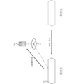
- FIGS. 9A to 9C show an example of the usage mode of the apparatus of this embodiment.
- an electrolysis device 10 including an electrolytic cell is sold or lent from a vendor to a vendor.
- the device 100 acquires operation history information of the electrolytic cell via the network N, and based on that, the management unit 154 of the device 100 determines the electrodes of the electrolytic cell.
- Usage history information is recorded (steps S802, S803).
- the electrolyzer 10 is collected from the customer to the seller, and maintenance and repair are performed at the seller.
- the vendor may perform repairs based on the future performance of the electrode output by the evaluation unit 157 of the device 100.
- the device 100 receives the repair history and records the electrode usage history information.
- the repaired electrolytic device 10 may be sold or lent again from the vendor to the vendor.
- the vendor may present information regarding the future performance of the electrode output by the evaluation section 157 of the device 100 as one of the quality assurance information. Note that the sales destination in FIG. 9A and the sales destination in FIG. 9C may be different.
- the program of this embodiment may be provided in a state stored in a computer-readable storage medium.
- the storage medium is a "non-temporary tangible medium” that can store the program.
- Programs include, by way of example and not limitation, software programs and computer programs.
Landscapes
- Chemical & Material Sciences (AREA)
- Engineering & Computer Science (AREA)
- Chemical Kinetics & Catalysis (AREA)
- Electrochemistry (AREA)
- Materials Engineering (AREA)
- Metallurgy (AREA)
- Organic Chemistry (AREA)
- Automation & Control Theory (AREA)
- Analytical Chemistry (AREA)
- Inorganic Chemistry (AREA)
- Electrolytic Production Of Metals (AREA)
- Electrolytic Production Of Non-Metals, Compounds, Apparatuses Therefor (AREA)
Abstract
Description
〔1〕
一又は複数の電解セルを備える電解槽の運転履歴情報に基づいて、前記電解セルが有する電極の使用履歴情報を記録する管理部を有する、
装置。
〔2〕
前記電極の前記使用履歴情報が、電極の補修履歴を含む、
〔1〕に記載の装置。
〔3〕
前記管理部は、前記使用履歴情報として、前記電極の金属量評価値をさらに記録する、
〔1〕又は〔2〕に記載の装置。
〔4〕
前記金属量評価値が、ルテニウム、ロジウム、パラジウム、オスミウム、イリジウム、及び白金からなる群より選ばれる貴金属のコーティング残量を含む、
〔3〕に記載の装置。
〔5〕
前記管理部は、前記電解セルが有する前記電極の、蛍光X線分析データ、誘導結合プラズマ発光分析データ、X線回折データ、又はX線光電子分光分析データを記録する、
〔1〕~〔4〕のいずれか一項に記載の装置。
〔6〕
前記電極の前記使用履歴情報に基づいて、前記電極の将来のパフォーマンスを評価する評価部を有する、
〔1〕~〔5〕のいずれか一項に記載の装置。
〔7〕
前記評価部は、前記金属量評価値及び不純物評価値の大小を評価し、評価結果に基づいて、パフォーマンスを最も延命できる、または一時的に最も向上できる補修内容を出力する、
〔6〕に記載の装置。
〔8〕
前記電解槽の運転条件を提案する運転提案部をさらに有し、
前記運転提案部は、前記使用履歴情報に基づいて、電流効率がより大きくなるようにするための前記運転条件を提案し、
前記運転条件は、電圧条件及び電解液の流量条件を含む、
〔1〕~〔7〕のいずれか一項に記載の装置。
〔9〕
前記電解槽の停止条件を提案する停止提案部をさらに有し、
前記停止提案部は、前記使用履歴情報に基づいて、電極の金属量が減少しにくい前記停止条件を提案し、
前記停止条件は、電流の減衰条件、及び/又は、電解液の流量の増加条件を含む、
〔1〕~〔8〕のいずれか一項に記載の装置。
〔10〕
前記電解槽が複数の前記電解セルを備え、
前記使用履歴情報に基づいて、前記電極の金属量又は不純物量が相対的に高い前記電解セルと前記電極の金属量又は不純物量が相対的に低い前記電解セルの、前記電解槽における位置の変更を提案する位置変更提案部をさらに有する、
〔1〕~〔9〕のいずれか一項に記載の装置。
〔11〕
前記評価部は、前記電極の前記使用履歴情報と、行う予定の補修方法と、に基づいて、補修後の前記電極の将来のパフォーマンスを評価する、
〔6〕に記載の装置。
〔12〕
装置が、
一又は複数の電解セルを備える電解槽の運転履歴情報に基づいて、前記電解セルが有する電極の使用履歴情報を記録する処理を実行する、
方法。
〔13〕
装置に、
一又は複数の電解セルを備える電解槽の運転履歴情報に基づいて、前記電解セルが有する電極の使用履歴情報を記録する処理を実行させる、
プログラム。
図1Aは、本実施形態の電解槽を構成する電解セルの一例を断面模式図として示したものである。電解セル90は、陽極室10と、陰極室20と、陽極室10及び陰極室20を隔離する隔壁29と、陽極室10に設置された陽極11と、陰極室20に設置された陰極21と、を備える。1つの電解セル90に属する陽極11及び陰極21は互いに電気的に接続されている。
電解セルが有する電極の貴金属コーティング残量は電解装置の運転とともに少しずつ減少する。その減少の程度は、運転時間や運転電圧などの運転条件、逆電流の発生などの運転トラブルなどによって影響を受ける。また、多数の電解槽が連なった複極式の電解槽を備える電解装置においては、その電解槽における電解セルの位置によって発生する逆電流の大きさなどが異なったりするため、電解槽における電解セルの位置によって、貴金属コーティング残量の減少の程度も異なる。
図3を参照しつつ、装置100のハードウェア構成について説明する。装置100は、例えば、プロセッサ110、通信インターフェース120、入出力インターフェース130、メモリ140、ストレージ150、及びこれらの構成要素を相互接続するための1つ又は複数の通信バス160を含む。
電解槽データ153は、電解槽30に関する情報や、電解槽30の運転履歴情報が、電解槽ごとに、格納していてもよい。図4A及び図4Bを参照しつつ、ストレージ150に記憶される電解槽データ153について説明する。
管理部154は、電解槽の運転履歴情報に基づいて、電解セルが有する電極の使用履歴情報を記録する。より具体的には、管理部154は、電解装置10の制御部70から、電解槽の運転履歴情報を取得すること、取得した運転履歴情報を電解槽データに記録すること、記録した運転履歴情報に基づいて、電解セルが有する電極の使用履歴情報を記録すること、を実行してもよい。なお、装置100の管理部154が電解槽の運転履歴情報を取得する先は、電解装置10の制御部70に限られない。
管理部154が実行する予測処理について説明する前に、貴金属コーティング残量の減少傾向について、図5A~図5Eを参照して説明する。
管理部154が実行する金属量評価値の算出処理は、特に限定されないが、例えば、運転履歴情報に含まれる値を変数として、電極の金属量評価値を算出する式を用いる方法が挙げられる。金属量評価値を算出する式としては、より具体的には、総運転時間や総通電量などの運転した総量を示す値や、運転電圧、運転温度、電流密度、電解液の種類などの定常運転時の条件を示す値を変数としたものが挙げられる。
管理部154が実行する不純物評価値の算出処理は、特に限定されないが、例えば、運転履歴情報に含まれる値を変数として、電極の不純物評価値を算出する式を用いる方法が挙げられる。不純物評価値を算出する式としては、より具体的には、総運転時間や総通電量などの運転した総量を示す値や、電解液の種類やそれに含まれる不純物の種類や量など運転時に不純物の要因となる値を変数としたものが挙げられる。また、不純物評価値には、不純物による電極の表面被覆率や、不純物の付着厚みと言った指標が含まれてもよい。
評価部157は、電極の使用履歴情報に基づいて、電極の将来のパフォーマンスを評価してもよい。また、評価部157は、電極の使用履歴情報と、行う予定の補修方法と、に基づいて、補修後の電極の将来のパフォーマンスを評価してもよい。
学習部156は、運転履歴に関する情報と、該運転履歴を経た電解槽の各電解セルが有する電極の金属量評価値又は不純物評価値に関する情報と、を含む学習用データ155に基づいて、機械学習処理を行い、学習済みモデルを得てもよい。このようにして得られる学習済みモデルは、管理部154が使用するモデルとなり、運転履歴に関する情報を入力とし、該運転履歴を経た電解槽の各電解セルが有する電極の金属量評価値又は不純物評価値に関する情報を出力とするものであってもよい。
運転提案部158は、電解槽30の運転条件を提案してもよい。具体的には、運転提案部158は、使用履歴情報に基づいて、電流効率がより大きくなるようにするための運転条件を提案することができる。
停止提案部159は、電解槽30の停止条件を提案してもよい。具体的には、停止提案部159は、使用履歴情報に基づいて、該電極の金属量が減少しにくい停止条件を提案することができる。
電解槽30が複数の電解セル90を備える場合には、位置変更提案部161は、使用履歴情報に基づいて、貴金属コーティング残量が相対的に高い電解セル90と貴金属コーティング残量が相対的に低い電解セル90の、電解槽における位置の変更を提案してもよい。
次に、本実施形態に係る装置の動作について説明する。図8は、本実施形態に係る装置が実行する処理の一例を示すシーケンス図である。
図9A~図9Cに、本実施形態の装置の使用態様の一例を示す。まず、図9Aに示すように、販売元から販売先へ電解槽を備える電解装置10を販売または貸与する。そして、販売先が電解装置10を使用すると、装置100は、ネットワークNを介して、電解槽の運転履歴情報を取得し、それに基づいて、装置100の管理部154が、電解セルが有する電極の使用履歴情報を記録する(ステップS802,S803)。
Claims (13)
- 一又は複数の電解セルを備える電解槽の運転履歴情報に基づいて、前記電解セルが有する電極の使用履歴情報を記録する管理部を有する、
装置。 - 前記電極の前記使用履歴情報が、電極の補修履歴を含む、
請求項1に記載の装置。 - 前記管理部は、前記使用履歴情報として、前記電極の金属量評価値を記録する、
請求項1に記載の装置。 - 前記金属量評価値が、ルテニウム、ロジウム、パラジウム、オスミウム、イリジウム、及び白金からなる群より選ばれる貴金属のコーティング残量を含む、
請求項3に記載の装置。 - 前記管理部は、前記電解セルが有する前記電極の、蛍光X線分析データ、誘導結合プラズマ発光分析データ、X線回折データ、又はX線光電子分光分析データを記録する、
請求項1に記載の装置。 - 前記電極の前記使用履歴情報に基づいて、前記電極の将来のパフォーマンスを評価する評価部を有する、
請求項1に記載の装置。 - 前記評価部は、前記金属量評価値及び不純物評価値の大小を評価し、評価結果に基づいて、パフォーマンスを最も延命できる、または一時的に最も向上できる補修内容を出力する、
請求項6に記載の装置。 - 前記電解槽の運転条件を提案する運転提案部をさらに有し、
前記運転提案部は、前記使用履歴情報に基づいて、電流効率がより大きくなるようにするための前記運転条件を提案し、
前記運転条件は、電圧条件及び電解液の流量条件を含む、
請求項1に記載の装置。 - 前記電解槽の停止条件を提案する停止提案部をさらに有し、
前記停止提案部は、前記使用履歴情報に基づいて、電極の金属量が減少しにくい前記停止条件を提案し、
前記停止条件は、電流の減衰条件、及び/又は、電解液の流量の増加条件を含む、
請求項1に記載の装置。 - 前記電解槽が複数の前記電解セルを備え、
前記使用履歴情報に基づいて、前記電極の金属量又は不純物量が相対的に高い前記電解セルと前記電極の金属量又は不純物量が相対的に低い前記電解セルの、前記電解槽における位置の変更を提案する位置変更提案部をさらに有する、
請求項1に記載の装置。 - 前記評価部は、前記電極の前記使用履歴情報と、行う予定の補修方法と、に基づいて、補修後の前記電極の将来のパフォーマンスを評価する、
請求項6に記載の装置。 - 装置が、
一又は複数の電解セルを備える電解槽の運転履歴情報に基づいて、前記電解セルが有する電極の使用履歴情報を記録する処理を実行する、
方法。 - 装置に、
一又は複数の電解セルを備える電解槽の運転履歴情報に基づいて、前記電解セルが有する電極の使用履歴情報を記録する処理を実行させる、
プログラム。
Priority Applications (6)
| Application Number | Priority Date | Filing Date | Title |
|---|---|---|---|
| CN202380042267.4A CN119384524A (zh) | 2022-06-30 | 2023-06-28 | 装置和方法 |
| JP2024530927A JP7823191B2 (ja) | 2022-06-30 | 2023-06-28 | 装置及び方法 |
| US18/879,380 US20250341011A1 (en) | 2022-06-30 | 2023-06-28 | Apparatus and method |
| AU2023300838A AU2023300838A1 (en) | 2022-06-30 | 2023-06-28 | Device and method |
| EP23831536.0A EP4549627A4 (en) | 2022-06-30 | 2023-06-28 | DEVICE AND PROCESS |
| KR1020247040604A KR20250005487A (ko) | 2022-06-30 | 2023-06-28 | 장치 및 방법 |
Applications Claiming Priority (2)
| Application Number | Priority Date | Filing Date | Title |
|---|---|---|---|
| JP2022105341 | 2022-06-30 | ||
| JP2022-105341 | 2022-06-30 |
Publications (1)
| Publication Number | Publication Date |
|---|---|
| WO2024005096A1 true WO2024005096A1 (ja) | 2024-01-04 |
Family
ID=89382375
Family Applications (1)
| Application Number | Title | Priority Date | Filing Date |
|---|---|---|---|
| PCT/JP2023/024033 Ceased WO2024005096A1 (ja) | 2022-06-30 | 2023-06-28 | 装置及び方法 |
Country Status (8)
| Country | Link |
|---|---|
| US (1) | US20250341011A1 (ja) |
| EP (1) | EP4549627A4 (ja) |
| JP (1) | JP7823191B2 (ja) |
| KR (1) | KR20250005487A (ja) |
| CN (1) | CN119384524A (ja) |
| AU (1) | AU2023300838A1 (ja) |
| TW (1) | TWI858797B (ja) |
| WO (1) | WO2024005096A1 (ja) |
Citations (7)
| Publication number | Priority date | Publication date | Assignee | Title |
|---|---|---|---|---|
| JP2001170642A (ja) * | 1999-12-17 | 2001-06-26 | Sanyo Electric Co Ltd | 水処理装置 |
| JP2018513276A (ja) * | 2015-04-20 | 2018-05-24 | イネオス テクノロジーズ ソシエテ アノニム | 電極アセンブリ、電極構造体及び電解槽 |
| CN108728864A (zh) * | 2017-04-17 | 2018-11-02 | 蓝星(北京)化工机械有限公司 | 一种电极涂层修复方法 |
| JP6670948B2 (ja) | 2016-11-22 | 2020-03-25 | 旭化成株式会社 | 電解用電極 |
| JP2021130859A (ja) * | 2020-02-21 | 2021-09-09 | パナソニックIpマネジメント株式会社 | 水素製造システム並びにその運転方法 |
| JP2021172867A (ja) | 2020-04-28 | 2021-11-01 | 旭化成株式会社 | 水電解用複極式電解槽 |
| CN114351189A (zh) * | 2021-10-13 | 2022-04-15 | 杭州三耐环保科技股份有限公司 | 一种电解生产监控方法和系统 |
Family Cites Families (8)
| Publication number | Priority date | Publication date | Assignee | Title |
|---|---|---|---|---|
| JP3406403B2 (ja) * | 1994-09-16 | 2003-05-12 | 田中貴金属工業株式会社 | 強酸性水用電極 |
| US6591199B2 (en) * | 2000-04-11 | 2003-07-08 | Recherche 2000 Inc. | Method and system for acquisition, monitoring, display and diagnosis of operational parameters of electrolyzers |
| JP2002012996A (ja) * | 2000-06-30 | 2002-01-15 | Nippon Mining & Metals Co Ltd | 電解製錬における異常電極の自動検出方法 |
| ITMI20101100A1 (it) * | 2010-06-17 | 2011-12-18 | Industrie De Nora Spa | Sistema per la generazione elettrochimica di ipoclorito |
| US10465302B2 (en) * | 2014-08-07 | 2019-11-05 | Marathon Systems, Inc. | Modular gaseous electrolysis apparatus with actively-cooled header module, co-disposed heat exchanger module and gas manifold modules therefor |
| US11339484B2 (en) | 2017-03-13 | 2022-05-24 | Asahi Kasei Kabushiki Kaisha | Electrolytic cell and electrolyzer |
| JP7381008B2 (ja) * | 2019-09-20 | 2023-11-15 | Eneos株式会社 | 水素発生システムの制御方法、および水素発生システム |
| PL4008806T3 (pl) * | 2020-11-30 | 2025-04-22 | Recherche 2000 Inc. | Sposoby i układy do wykrywania zanieczyszczeń w ogniwach do elektrolizy |
-
2023
- 2023-06-28 AU AU2023300838A patent/AU2023300838A1/en active Pending
- 2023-06-28 KR KR1020247040604A patent/KR20250005487A/ko active Pending
- 2023-06-28 JP JP2024530927A patent/JP7823191B2/ja active Active
- 2023-06-28 US US18/879,380 patent/US20250341011A1/en active Pending
- 2023-06-28 EP EP23831536.0A patent/EP4549627A4/en active Pending
- 2023-06-28 WO PCT/JP2023/024033 patent/WO2024005096A1/ja not_active Ceased
- 2023-06-28 CN CN202380042267.4A patent/CN119384524A/zh active Pending
- 2023-06-30 TW TW112124528A patent/TWI858797B/zh active
Patent Citations (7)
| Publication number | Priority date | Publication date | Assignee | Title |
|---|---|---|---|---|
| JP2001170642A (ja) * | 1999-12-17 | 2001-06-26 | Sanyo Electric Co Ltd | 水処理装置 |
| JP2018513276A (ja) * | 2015-04-20 | 2018-05-24 | イネオス テクノロジーズ ソシエテ アノニム | 電極アセンブリ、電極構造体及び電解槽 |
| JP6670948B2 (ja) | 2016-11-22 | 2020-03-25 | 旭化成株式会社 | 電解用電極 |
| CN108728864A (zh) * | 2017-04-17 | 2018-11-02 | 蓝星(北京)化工机械有限公司 | 一种电极涂层修复方法 |
| JP2021130859A (ja) * | 2020-02-21 | 2021-09-09 | パナソニックIpマネジメント株式会社 | 水素製造システム並びにその運転方法 |
| JP2021172867A (ja) | 2020-04-28 | 2021-11-01 | 旭化成株式会社 | 水電解用複極式電解槽 |
| CN114351189A (zh) * | 2021-10-13 | 2022-04-15 | 杭州三耐环保科技股份有限公司 | 一种电解生产监控方法和系统 |
Non-Patent Citations (1)
| Title |
|---|
| See also references of EP4549627A4 |
Also Published As
| Publication number | Publication date |
|---|---|
| TWI858797B (zh) | 2024-10-11 |
| TW202405952A (zh) | 2024-02-01 |
| AU2023300838A1 (en) | 2025-01-09 |
| KR20250005487A (ko) | 2025-01-09 |
| JPWO2024005096A1 (ja) | 2024-01-04 |
| JP7823191B2 (ja) | 2026-03-03 |
| US20250341011A1 (en) | 2025-11-06 |
| EP4549627A4 (en) | 2025-11-05 |
| CN119384524A (zh) | 2025-01-28 |
| EP4549627A1 (en) | 2025-05-07 |
Similar Documents
| Publication | Publication Date | Title |
|---|---|---|
| Goyal et al. | Competition between CO2 reduction and hydrogen evolution on a gold electrode under well-defined mass transport conditions | |
| Li et al. | Investigating low and high load cycling tests as accelerated stress tests for proton exchange membrane water electrolysis | |
| JP6929378B2 (ja) | 電気分解用陽極及びその製造方法 | |
| JP7429919B2 (ja) | 水素発生システム、水素発生システムの制御装置および水素発生システムの制御方法 | |
| JP2023552870A (ja) | マイクログリッドを制御する制御システムおよび方法 | |
| JP6590762B2 (ja) | 電力供給システム | |
| CN112805732A (zh) | 计划装置、计划方法以及计划程序 | |
| JP2020084259A (ja) | 水電解システム | |
| JP2020525644A5 (ja) | ||
| Zhang et al. | Machine learning assisted health status analysis and degradation prediction of aging proton exchange membrane fuel cells | |
| JP4595367B2 (ja) | 燃料電池の劣化診断方法及び装置 | |
| JP7823191B2 (ja) | 装置及び方法 | |
| JP7826478B2 (ja) | 装置及び方法 | |
| CN117129880B (zh) | 一种铅酸蓄电池的可用容量估算及健康状态评估方法 | |
| JP5640625B2 (ja) | 燃料電池システムおよび燃料電池システムの判定方法 | |
| Ehlers et al. | Nickel anode evolution and mass loss during intermittent alkaline water electrolysis | |
| Rizwan et al. | Reliability and sensitivity analysis of membrane biofilm fuel cell | |
| JP5718328B2 (ja) | プロトン交換膜燃料電池の耐用年数を延ばすための方法および装置 | |
| KR20160076382A (ko) | 불용성 전극의 수명 평가 장치 및 방법 | |
| EP4585722A1 (en) | Repair instruction device and repair instruction method | |
| Hodnik | Dissolution of Platinum in the Operational Range of Fuel Cells | |
| EA048364B1 (ru) | Система и способ управления микросетью электролизеров с анионообменной мембраной | |
| JP2025176907A (ja) | 電解システム及び電解システムの診断方法 | |
| FATHI et al. | DEGRADATION MECHANISM OF AN IRO 2 ANODE CO-CATALYST FOR CELL VOLTAGE REVERSAL MITIGATION UNDER TRANSIENT OPERATION CONDITIONS OF A PEM FUEL CELL | |
| JP2026046745A (ja) | データ処理方法、プログラム、データ処理装置、電池管理方法及び電池管理システム |
Legal Events
| Date | Code | Title | Description |
|---|---|---|---|
| 121 | Ep: the epo has been informed by wipo that ep was designated in this application |
Ref document number: 23831536 Country of ref document: EP Kind code of ref document: A1 |
|
| WWE | Wipo information: entry into national phase |
Ref document number: 2024530927 Country of ref document: JP |
|
| WWE | Wipo information: entry into national phase |
Ref document number: 202380042267.4 Country of ref document: CN |
|
| ENP | Entry into the national phase |
Ref document number: 20247040604 Country of ref document: KR Kind code of ref document: A |
|
| WWE | Wipo information: entry into national phase |
Ref document number: 1020247040604 Country of ref document: KR |
|
| WWE | Wipo information: entry into national phase |
Ref document number: AU2023300838 Country of ref document: AU |
|
| WWE | Wipo information: entry into national phase |
Ref document number: 202417103163 Country of ref document: IN |
|
| WWE | Wipo information: entry into national phase |
Ref document number: 18879380 Country of ref document: US |
|
| ENP | Entry into the national phase |
Ref document number: 2023300838 Country of ref document: AU Date of ref document: 20230628 Kind code of ref document: A |
|
| WWP | Wipo information: published in national office |
Ref document number: 202380042267.4 Country of ref document: CN |
|
| WWE | Wipo information: entry into national phase |
Ref document number: 2023831536 Country of ref document: EP |
|
| NENP | Non-entry into the national phase |
Ref country code: DE |
|
| ENP | Entry into the national phase |
Ref document number: 2023831536 Country of ref document: EP Effective date: 20250130 |
|
| WWP | Wipo information: published in national office |
Ref document number: 2023831536 Country of ref document: EP |
|
| WWP | Wipo information: published in national office |
Ref document number: 18879380 Country of ref document: US |