WO2024009602A1 - 可燃性ガス - Google Patents
可燃性ガス Download PDFInfo
- Publication number
- WO2024009602A1 WO2024009602A1 PCT/JP2023/017490 JP2023017490W WO2024009602A1 WO 2024009602 A1 WO2024009602 A1 WO 2024009602A1 JP 2023017490 W JP2023017490 W JP 2023017490W WO 2024009602 A1 WO2024009602 A1 WO 2024009602A1
- Authority
- WO
- WIPO (PCT)
- Prior art keywords
- gas
- ethylene
- container
- hydrogen
- concentration
- Prior art date
- Legal status (The legal status is an assumption and is not a legal conclusion. Google has not performed a legal analysis and makes no representation as to the accuracy of the status listed.)
- Ceased
Links
Images

Classifications
-
- C—CHEMISTRY; METALLURGY
- C10—PETROLEUM, GAS OR COKE INDUSTRIES; TECHNICAL GASES CONTAINING CARBON MONOXIDE; FUELS; LUBRICANTS; PEAT
- C10L—FUELS NOT OTHERWISE PROVIDED FOR; NATURAL GAS; SYNTHETIC NATURAL GAS OBTAINED BY PROCESSES NOT COVERED BY SUBCLASSES C10G OR C10K; LIQUIFIED PETROLEUM GAS; USE OF ADDITIVES TO FUELS OR FIRES; FIRE-LIGHTERS
- C10L3/00—Gaseous fuels; Natural gas; Synthetic natural gas obtained by processes not covered by subclass C10G, C10K; Liquefied petroleum gas
-
- B—PERFORMING OPERATIONS; TRANSPORTING
- B23—MACHINE TOOLS; METAL-WORKING NOT OTHERWISE PROVIDED FOR
- B23K—SOLDERING OR UNSOLDERING; WELDING; CLADDING OR PLATING BY SOLDERING OR WELDING; CUTTING BY APPLYING HEAT LOCALLY, e.g. FLAME CUTTING; WORKING BY LASER BEAM
- B23K7/00—Cutting, scarfing, or desurfacing by applying flames
- B23K7/10—Auxiliary devices, e.g. for guiding or supporting the torch
-
- C—CHEMISTRY; METALLURGY
- C10—PETROLEUM, GAS OR COKE INDUSTRIES; TECHNICAL GASES CONTAINING CARBON MONOXIDE; FUELS; LUBRICANTS; PEAT
- C10L—FUELS NOT OTHERWISE PROVIDED FOR; NATURAL GAS; SYNTHETIC NATURAL GAS OBTAINED BY PROCESSES NOT COVERED BY SUBCLASSES C10G OR C10K; LIQUIFIED PETROLEUM GAS; USE OF ADDITIVES TO FUELS OR FIRES; FIRE-LIGHTERS
- C10L2200/00—Components of fuel compositions
- C10L2200/02—Inorganic or organic compounds containing atoms other than C, H or O, e.g. organic compounds containing heteroatoms or metal organic complexes
- C10L2200/0277—Hydrogen
-
- C—CHEMISTRY; METALLURGY
- C10—PETROLEUM, GAS OR COKE INDUSTRIES; TECHNICAL GASES CONTAINING CARBON MONOXIDE; FUELS; LUBRICANTS; PEAT
- C10L—FUELS NOT OTHERWISE PROVIDED FOR; NATURAL GAS; SYNTHETIC NATURAL GAS OBTAINED BY PROCESSES NOT COVERED BY SUBCLASSES C10G OR C10K; LIQUIFIED PETROLEUM GAS; USE OF ADDITIVES TO FUELS OR FIRES; FIRE-LIGHTERS
- C10L2200/00—Components of fuel compositions
- C10L2200/04—Organic compounds
-
- C—CHEMISTRY; METALLURGY
- C10—PETROLEUM, GAS OR COKE INDUSTRIES; TECHNICAL GASES CONTAINING CARBON MONOXIDE; FUELS; LUBRICANTS; PEAT
- C10L—FUELS NOT OTHERWISE PROVIDED FOR; NATURAL GAS; SYNTHETIC NATURAL GAS OBTAINED BY PROCESSES NOT COVERED BY SUBCLASSES C10G OR C10K; LIQUIFIED PETROLEUM GAS; USE OF ADDITIVES TO FUELS OR FIRES; FIRE-LIGHTERS
- C10L2270/00—Specifically adapted fuels
- C10L2270/08—Specifically adapted fuels for small applications, such as tools, lamp oil, welding
Definitions
- the present invention relates to combustible gas.
- a gas cutting method that uses flammable gas to cut a target object is known.
- a mixed gas in which combustible gas is mixed with oxygen gas is combusted, and the object is preheated with the heat. Then, when the object is sufficiently preheated, oxygen gas for fusing is further supplied, and the object is oxidized and cut by fusing.
- the applicant has proposed a combustible gas containing 38% by volume or more and 45% by volume or less of ethylene, with the remainder being hydrogen and inevitable impurities (see Japanese Patent No. 4848060).
- This combustible gas is easy to store, transport, etc., and can contribute to improving the quality of the finished product after gas cutting.
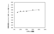
- the hydrocarbon gas contained in the combustible gas contributes to the calorie source, that is, the thermal power, and increases the combustion intensity. For this reason, in the conventional combustible gas, the ethylene concentration is set near where the combustion intensity is maximum, as shown in FIG. In this way, the hydrocarbon gas concentration is generally set to increase the combustion intensity.
- the present invention was made as a result of day and night research and development aimed at developing flammable gas with lower CO 2 emissions as a company that provides flammable gas.
- the purpose is to provide a flammable gas that can reduce the amount of CO 2 generated when cutting objects.
- the amount of CO2 gas generated is determined by the hydrocarbon gas content contained in the combustible gas x the fusing time, so for the above flammable gas, lowering the ethylene concentration has the effect of reducing the hydrocarbon gas content.
- the present invention was completed based on the discovery that this greatly outweighs the effect of a longer fusing time and can greatly reduce the amount of CO 2 gas generated.
- the flammable gas according to one aspect of the present invention is a combustible gas used as a combustion gas for gas cutting of a target, and includes ethylene with a concentration of more than 0% by volume and less than 18% by volume, and the remainder is hydrogen and It is an unavoidable impurity.
- the concentration of ethylene which is a hydrocarbon gas, is suppressed to be lower than the ethylene concentration at which the combustion intensity is maximum, and the reduction in fusing speed is small, so the amount of CO 2 gas generated can be effectively reduced. Can be done.
- the flammable gas is preferably sealed in a container, and the pressure in the container is preferably 1 MPa or more and 50 MPa or less at 35°C.
- the pressure in the container is preferably 1 MPa or more and 50 MPa or less at 35°C.
- the concentration of the above-mentioned unavoidable impurities is preferably 1.0% by volume or less.
- the above-mentioned object is a steel material.
- the combustible gas can be particularly suitably used for cutting steel materials.
- the flammable gas of the present invention can reduce the amount of CO 2 generated when cutting an object.
- FIG. 1 is a graph showing the relationship between ethylene concentration and combustion intensity.
- FIG. 2 is a graph showing the relationship between ethylene concentration and fusing speed.
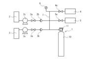
- FIG. 3 is a schematic diagram showing an example of the flammable gas manufacturing equipment of the present invention.
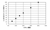
- FIG. 4 is a graph showing the relationship between ethylene concentration and CO 2 generation amount in Examples.
- the combustible gas according to one aspect of the present invention is a combustible gas used as a combustion gas for gas cutting of an object.
- the above-mentioned object is a metal material that can be cut by flame, or in other words, it is a metal material that oxidizes when exposed to oxygen at high temperatures.
- Examples of the object include steel materials, titanium materials, and the like.
- the above-mentioned object is preferably a steel material, and more preferably a general structural rolled steel material.
- the combustible gas can be particularly suitably used for cutting steel materials.
- the combustible gas contains ethylene with a concentration of more than 0% by volume and less than 38% by volume, with the remainder being hydrogen and inevitable impurities.
- the lower limit of the ethylene concentration is preferably 1% by volume, more preferably 5% by volume.
- the ethylene concentration is preferably less than 18% by volume, more preferably less than 15% by volume.
- the upper limit of the content of the inevitable impurities is preferably 1.0% by volume, more preferably 0.5% by volume, and even more preferably 0.1% by volume.
- the lower limit of the content of the inevitable impurities is not particularly limited and may be 0% by volume.
- the term "inevitable impurities” includes impurities that are unintentionally included as well as impurities that are intentionally added within a range that maintains the performance of the combustible gas. Examples of impurities intentionally added in this way include nitrogen, oxygen, moisture, and the like.
- the flammable gas is stored under pressure in a container or tank. Above all, it is preferable that the combustible gas is sealed in a container. By sealing the flammable gas in the container in this way, handling efficiency can be improved.
- the pressure inside the container is preferably below the pressure at which the gas sealed in the container does not liquefy, and from the viewpoint of transportation efficiency, the pressure is preferably higher.
- the lower limit of the pressure inside the container is preferably 1 MPa, more preferably 6 MPa, and even more preferably 15 MPa at 35°C.
- the upper limit of the pressure is preferably 50 MPa, more preferably 20 MPa. If the pressure is less than the lower limit, it may be difficult to efficiently transport the combustible gas. Conversely, if the pressure exceeds the upper limit, ethylene may liquefy and become difficult to handle. Since the flammable gas has a relatively low ethylene concentration, it is difficult to liquefy even if the pressure inside the container is relatively high. Therefore, by increasing the pressure, the amount of filling in the container can be increased and the transport efficiency can be increased.
- the combustible gas can be sealed in the container 1 using the manufacturing equipment shown in FIG. 3, for example.
- the above manufacturing equipment includes a hydrogen gas storage section 2, an ethylene gas storage section 3, a gas discharge section 4, a pressure reducing device 5, a pressure gauge 6, a hydrogen gas storage section 2, an ethylene gas storage section 3, and a gas discharge section. 4, a pipe 7 connecting the pressure reducing device 5 and the pressure gauge 6 to the container 1 is provided.
- the container 1 includes a main body 10 that stores flammable gas, and a container valve 11 attached to the main body 10. Piping 7 is connected to container valve 11.
- hydrogen gas is stored in the hydrogen gas storage section 2, and is connected to the pipe 7 via a hydrogen valve 2a and a hydrogen check valve 2b.
- Ethylene gas is stored in the ethylene gas storage section 3, and is connected to the pipe 7 via an ethylene valve 3a and an ethylene check valve 3b.
- the hydrogen check valve 2b and the ethylene check valve 3b prevent hydrogen gas and ethylene gas from flowing back into the hydrogen gas storage section 2 and the ethylene gas storage section 3, respectively.
- a hydrogen compressor 2c is provided which compresses and pressurizes the hydrogen gas in the hydrogen gas storage section 2, and a hydrogen compressor 2c which compresses and pressurizes the hydrogen gas in the hydrogen gas storage section 3.
- An ethylene compressor 3c for pressurization may be provided at the outlet of the hydrogen gas storage section 2 and the ethylene gas storage section 3, respectively.
- the gas discharge part 4 can safely discharge the gas inside the pipe 7 to the outside.
- the gas discharge section 4 is connected to the pipe 7 via a gas discharge valve 4a.
- the pressure reducing device 5 includes, for example, a vacuum pump, and can manage the pressure inside the piping 7.
- the pressure reducing device 5 is connected to the pipe 7 via a pressure reducing valve 5a.
- the method for producing combustible gas includes an evacuation step, an ethylene gas filling step, a hydrogen gas filling step, and a container removal step.
- the container valve 11 is opened, and the pressure gauge 6 indicates that the combustible gas is at a specified pressure or higher.
- the release valve 4a is opened and the flammable gas is released from the gas release section 4. After that, the discharge valve 4a is closed.
- the pressure reducing valve 5a is opened to reduce the pressure inside the main body 10 and the pipe 7. Once the pressure is reduced to a desired level, the pressure reduction valve 5a is closed. Note that this operation is performed even if the discharge valve 4a is not opened. That is, after the above-mentioned evacuation step, the main body portion 10 is depressurized.
- the ethylene valve 3a is opened and the main body 10 is filled with ethylene gas in the ethylene gas storage section 3.
- the pressure of the main body 10 that is, the pressure of the pressure gauge 6
- the pressure (partial pressure) required to reduce the ethylene concentration in the combustible gas after production to more than 0% by volume and less than 38% by volume
- the ethylene Close the valve 3a More specifically, when the pressure of the combustible gas after production is P and the partial pressure of ethylene gas is p, determine the partial pressure p so that p/P is the desired ethylene concentration, and calculate the partial pressure It is preferable to close the ethylene valve 3a when the temperature reaches p.
- the hydrogen valve 2a is opened and the main body 10 is filled with hydrogen gas in the hydrogen gas storage section 2.
- the pressure of the main body 10 that is, the pressure of the pressure gauge 6
- the hydrogen valve 2a is turned on. close. More specifically, the hydrogen valve 2a may be closed when the pressure of the combustible gas reaches P.
- Container removal process In the container removal step, the container valve 11 of the container 1 filled with ethylene gas and hydrogen gas is closed, and the container 1 is removed from the pipe 7. In this way, the container 1 can be filled with the flammable gas.
- the ethylene gas and hydrogen gas filled in the container 1 will be in a uniformly mixed state after a predetermined time has passed after filling.
- each gas when filling the container with the flammable gas, each gas was filled so as to have a desired partial pressure.
- the mixed gas can also be pressurized using a compressor and then filled into a container.
- the flammable gas is filled into the container, but the flammable gas is mixed with ethylene gas and hydrogen gas at the location where the fusing is performed, and the mixture is filled into the container. It may be used without.
- ⁇ CO2 generation amount> There are six types of combustible gases containing ethylene and the remainder being hydrogen and inevitable impurities, with ethylene concentrations of 5% by volume, 10% by volume, 15% by volume, 20% by volume, 30% by volume, and 40% by volume. I prepared the gas.
- a general structural rolled steel material with a plate thickness of 25 mm was prepared. Using each combustible gas, 300 mm of the above-mentioned rolled steel for general structure was melt-cut, and the melt-cut time was measured. When cutting steel with flammable gas, cutting does not start until the steel is heated, but this time is not included in the cutting time. That is, the fusing time is the time from the start of fusing until the fusing of 300 mm is completed. Note that the flow rate of the combustible gas during the melting was 8 L/min.
- FIG. 4 shows the relationship between ethylene concentration and CO 2 generation amount (ethylene concentration x fusing time).
- the ethylene concentration x fusing time is normalized and shown as 100 when a combustible gas with an ethylene concentration of 40% by volume is used.
- Evaluation criteria are as follows. (Evaluation criteria) A: The white core can be clearly seen, which is good. B: The white core can be visually recognized and there is no problem in practical use. C: Although the white core is faintly visible, it is difficult to visually recognize the white core, which is not practical. D: White core cannot be visually recognized.
- the flammable gas of the present invention can reduce the amount of CO 2 generated when cutting an object.
- Container 10 Main body 11 Container valve 2 Hydrogen gas storage section 2a Hydrogen valve 2b Hydrogen check valve 2c Hydrogen compressor 3 Ethylene gas storage section 3a Ethylene valve 3b Ethylene check valve 3c Ethylene compressor 4 Gas Discharge part 4a Discharge valve 5 Pressure reducing device 5a Pressure reducing valve 6 Pressure gauge 7 Piping
Landscapes
- Chemical & Material Sciences (AREA)
- Oil, Petroleum & Natural Gas (AREA)
- Engineering & Computer Science (AREA)
- Chemical Kinetics & Catalysis (AREA)
- General Chemical & Material Sciences (AREA)
- Organic Chemistry (AREA)
- Mechanical Engineering (AREA)
- Filling Or Discharging Of Gas Storage Vessels (AREA)
- Pressure Welding/Diffusion-Bonding (AREA)
Abstract
Description
当該可燃性ガスは、濃度0体積%超38体積%未満のエチレンを含み、残部が水素及び不可避的不純物である。
当該可燃性ガスは、例えば図3に示す製造設備を用いて、容器1内に封入することができる。上記製造設備は、水素ガス貯蔵部2と、エチレンガス貯蔵部3と、ガス放出部4と、減圧装置5と、圧力計6と、水素ガス貯蔵部2、エチレンガス貯蔵部3、ガス放出部4、減圧装置5及び圧力計6を容器1に接続する配管7とを備える。
上記排気工程では、容器1の本体部10に残留しているガスを放出する。
上記エチレンガス充填工程では、上記排気工程で減圧された本体部10にエチレンガスを充填する。
上記水素ガス充填工程では、上記エチレンガス充填工程後の本体部10に水素ガスを充填する。
上記容器取外工程では、エチレンガス及び水素ガスが充填された容器1の容器弁11を閉じ、配管7から容器1を取り外す。このようにして容器1に当該可燃性ガスを充填することができる。
当該可燃性ガスは、炭化水素ガスであるエチレン濃度が、燃焼強度が最大となるエチレン濃度より低く抑えられながら、溶断速度の低下が少ないため、CO2ガスの発生量を効果的に低減することができる。
上記実施形態は、本発明の構成を限定するものではない。従って、上記実施形態は、本明細書の記載及び技術常識に基づいて上記実施形態各部の構成要素の省略、置換又は追加が可能であり、それらは全て本発明の範囲に属するものと解釈されるべきである。
エチレンを含み、残部が水素及び不可避的不純物である可燃性ガスとして、エチレン濃度が5体積%、10体積%、15体積%、20体積%、30体積%、40体積%の6種類の可燃性ガスを準備した。
エチレンを含み、残部が水素及び不可避的不純物である可燃性ガスとして、エチレン濃度が表1に示す7種類の可燃性ガスを準備した。
(評価基準)
A :はっきりと白芯を視認することができ、良好である。
B :白芯を視認することができ、実用上問題がない。
C :かすかに見えるものの白芯を視認することが困難であり、実用的ではない。
D :白芯を視認することができない。

10 本体部
11 容器弁
2 水素ガス貯蔵部
2a 水素用弁
2b 水素用逆止弁
2c 水素用圧縮機
3 エチレンガス貯蔵部
3a エチレン用弁
3b エチレン用逆止弁
3c エチレン用圧縮機
4 ガス放出部
4a 放出用弁
5 減圧装置
5a 減圧用弁
6 圧力計
7 配管
Claims (4)
- 対象物のガス溶断に燃焼ガスとして用いられる可燃性ガスであって、
濃度0体積%超18体積%未満のエチレンを含み、残部が水素及び不可避的不純物である可燃性ガス。 - 容器内に封入され、上記容器内の圧力が35℃において1MPa以上50MPa以下である請求項1に記載の可燃性ガス。
- 上記不可避的不純物の濃度が1.0体積%以下である請求項1又は請求項2に記載の可燃性ガス。
- 上記対象物が鋼材である請求項1又は請求項2に記載の可燃性ガス。
Priority Applications (6)
| Application Number | Priority Date | Filing Date | Title |
|---|---|---|---|
| MYPI2024007364A MY210255A (en) | 2022-07-08 | 2023-05-09 | Combustible gas |
| CN202380021696.3A CN118696108A (zh) | 2022-07-08 | 2023-05-09 | 可燃性气体 |
| US18/682,217 US20240263093A1 (en) | 2022-07-08 | 2023-05-09 | Combustible gas |
| EP23835143.1A EP4357061B1 (en) | 2022-07-08 | 2023-05-09 | Combustible gas |
| KR1020247033356A KR102876751B1 (ko) | 2022-07-08 | 2023-05-09 | 가연성 가스 |
| US19/383,957 US20260062634A1 (en) | 2022-07-08 | 2025-11-10 | Combustible gas |
Applications Claiming Priority (2)
| Application Number | Priority Date | Filing Date | Title |
|---|---|---|---|
| JP2022-110098 | 2022-07-08 | ||
| JP2022110098A JP7170159B1 (ja) | 2022-07-08 | 2022-07-08 | 可燃性ガス |
Related Child Applications (2)
| Application Number | Title | Priority Date | Filing Date |
|---|---|---|---|
| US18/682,217 A-371-Of-International US20240263093A1 (en) | 2022-07-08 | 2023-05-09 | Combustible gas |
| US19/383,957 Continuation US20260062634A1 (en) | 2022-07-08 | 2025-11-10 | Combustible gas |
Publications (1)
| Publication Number | Publication Date |
|---|---|
| WO2024009602A1 true WO2024009602A1 (ja) | 2024-01-11 |
Family
ID=83996951
Family Applications (1)
| Application Number | Title | Priority Date | Filing Date |
|---|---|---|---|
| PCT/JP2023/017490 Ceased WO2024009602A1 (ja) | 2022-07-08 | 2023-05-09 | 可燃性ガス |
Country Status (7)
| Country | Link |
|---|---|
| US (2) | US20240263093A1 (ja) |
| EP (1) | EP4357061B1 (ja) |
| JP (1) | JP7170159B1 (ja) |
| KR (1) | KR102876751B1 (ja) |
| CN (1) | CN118696108A (ja) |
| MY (1) | MY210255A (ja) |
| WO (1) | WO2024009602A1 (ja) |
Families Citing this family (1)
| Publication number | Priority date | Publication date | Assignee | Title |
|---|---|---|---|---|
| DE102023128801A1 (de) | 2023-10-19 | 2025-04-24 | Messer Cutting Systems Gmbh | Brenngasgemisch für die autogene Bearbeitung von Metallen |
Citations (4)
| Publication number | Priority date | Publication date | Assignee | Title |
|---|---|---|---|---|
| JPS53118401A (en) * | 1977-03-24 | 1978-10-16 | Daido Oxygen | Inflammable gas for welding* cutting by fusion and heating metals |
| JP4848060B1 (ja) | 2011-03-11 | 2011-12-28 | 岩谷瓦斯株式会社 | 可燃性ガス |
| JP5386658B1 (ja) * | 2012-06-26 | 2014-01-15 | 岩谷瓦斯株式会社 | 可燃性ガスおよび鋼材のロウ付け方法 |
| JP3189711U (ja) * | 2014-01-14 | 2014-03-27 | 岩谷瓦斯株式会社 | 溶断用火口 |
Family Cites Families (6)
| Publication number | Priority date | Publication date | Assignee | Title |
|---|---|---|---|---|
| JP4542417B2 (ja) * | 2004-11-26 | 2010-09-15 | 新日鉄エンジニアリング株式会社 | 廃棄物溶融炉の可燃性ガスの処理方法 |
| CN101617030B (zh) * | 2006-10-31 | 2014-10-22 | 大阪瓦斯株式会社 | 可燃性气体浓缩系统 |
| CN101878285B (zh) * | 2007-07-25 | 2015-05-06 | 大阪瓦斯株式会社 | 可燃气体处理系统和可燃气体处理方法 |
| US20130032250A1 (en) * | 2010-04-20 | 2013-02-07 | Taiyo Nippon Sanso Corporation | Gas cutting method, gas cutting machine, and cutting tip |
| JP6162377B2 (ja) * | 2012-08-06 | 2017-07-12 | 岩谷瓦斯株式会社 | 可燃性ガスおよび鋼材の溶断方法 |
| KR20240129468A (ko) * | 2023-02-20 | 2024-08-27 | 에스케이하이닉스 주식회사 | 이미지 센서, 이미지 촬영 장치, 이미지 센서를 이용한 난수 생성 시스템 |
-
2022
- 2022-07-08 JP JP2022110098A patent/JP7170159B1/ja active Active
-
2023
- 2023-05-09 US US18/682,217 patent/US20240263093A1/en not_active Abandoned
- 2023-05-09 MY MYPI2024007364A patent/MY210255A/en unknown
- 2023-05-09 CN CN202380021696.3A patent/CN118696108A/zh active Pending
- 2023-05-09 WO PCT/JP2023/017490 patent/WO2024009602A1/ja not_active Ceased
- 2023-05-09 KR KR1020247033356A patent/KR102876751B1/ko active Active
- 2023-05-09 EP EP23835143.1A patent/EP4357061B1/en active Active
-
2025
- 2025-11-10 US US19/383,957 patent/US20260062634A1/en active Pending
Patent Citations (4)
| Publication number | Priority date | Publication date | Assignee | Title |
|---|---|---|---|---|
| JPS53118401A (en) * | 1977-03-24 | 1978-10-16 | Daido Oxygen | Inflammable gas for welding* cutting by fusion and heating metals |
| JP4848060B1 (ja) | 2011-03-11 | 2011-12-28 | 岩谷瓦斯株式会社 | 可燃性ガス |
| JP5386658B1 (ja) * | 2012-06-26 | 2014-01-15 | 岩谷瓦斯株式会社 | 可燃性ガスおよび鋼材のロウ付け方法 |
| JP3189711U (ja) * | 2014-01-14 | 2014-03-27 | 岩谷瓦斯株式会社 | 溶断用火口 |
Non-Patent Citations (1)
| Title |
|---|
| See also references of EP4357061A4 |
Also Published As
| Publication number | Publication date |
|---|---|
| KR20240151874A (ko) | 2024-10-18 |
| JP7170159B1 (ja) | 2022-11-11 |
| US20240263093A1 (en) | 2024-08-08 |
| MY210255A (en) | 2025-09-04 |
| EP4357061A4 (en) | 2024-12-25 |
| CN118696108A (zh) | 2024-09-24 |
| JP2024008322A (ja) | 2024-01-19 |
| KR102876751B1 (ko) | 2025-10-27 |
| US20260062634A1 (en) | 2026-03-05 |
| EP4357061A1 (en) | 2024-04-24 |
| EP4357061B1 (en) | 2026-05-06 |
Similar Documents
| Publication | Publication Date | Title |
|---|---|---|
| KR101341240B1 (ko) | 가연성 가스 | |
| WO2024009602A1 (ja) | 可燃性ガス | |
| US20160238278A1 (en) | Method for using an environmentally friendly fuel gas within a refillable gas container | |
| JP2015009247A (ja) | 溶接用ソリッドワイヤおよび溶接方法並びに溶接金属 | |
| KR20210070819A (ko) | 내부식성이 향상된 보일러 튜브 및 보일러튜브의 코팅방법 | |
| JP2020075276A (ja) | サブマージアーク溶接用溶融型フラックス | |
| CN107442966A (zh) | 一种适用于高强钢水下焊用自保护药芯焊丝 | |
| CN102699564A (zh) | 高性能铝合金自动焊丝 | |
| EP0952205B1 (fr) | Mélange gazeux constitué de l'acétylène et soit de l'hydrogène ou du gaz naturel | |
| JP2013000771A (ja) | サブマージアーク肉盛溶接用フラックス | |
| JP6162377B2 (ja) | 可燃性ガスおよび鋼材の溶断方法 | |
| CN120858161A (zh) | 用于金属的氧-燃料加工的燃料气体混合物 | |
| JP6318704B2 (ja) | サブマージアーク溶接用溶融型フラックス | |
| JP2014169431A (ja) | 溶断用燃料ガスおよびそれを充填してなる高圧ガス容器 | |
| JP5738254B2 (ja) | 可燃性ガスおよび鋼材の溶断方法 | |
| CN118745538B (zh) | 一种低温高压储氢瓶和内衬的制备方法 | |
| US6692550B2 (en) | Fabrication of a high-strength steel article with inclusion control during melting | |
| KR20250091561A (ko) | 스테인리스강용 피복 아크 용접봉 및 이로부터 얻어진 용착금속 | |
| JP2005040845A (ja) | 低水素系被覆アーク溶接棒 | |
| Smith et al. | Instruction Book on Oxy-acetylene Welding and Cutting | |
| CN120965330A (zh) | 一种高炉开口钻具用耐磨金属陶瓷复合材料及其制备方法 | |
| TW202233344A (zh) | 銲道裂紋的修補方法 | |
| FR2774693A1 (fr) | Melange gazeux combustible, notamment pour chalumeau d'oxycoupage |
Legal Events
| Date | Code | Title | Description |
|---|---|---|---|
| WWE | Wipo information: entry into national phase |
Ref document number: 2023835143 Country of ref document: EP |
|
| ENP | Entry into the national phase |
Ref document number: 2023835143 Country of ref document: EP Effective date: 20240119 |
|
| 121 | Ep: the epo has been informed by wipo that ep was designated in this application |
Ref document number: 23835143 Country of ref document: EP Kind code of ref document: A1 |
|
| WWE | Wipo information: entry into national phase |
Ref document number: 11202400303U Country of ref document: SG |
|
| WWE | Wipo information: entry into national phase |
Ref document number: 202380021696.3 Country of ref document: CN |
|
| ENP | Entry into the national phase |
Ref document number: 20247033356 Country of ref document: KR Kind code of ref document: A |
|
| WWE | Wipo information: entry into national phase |
Ref document number: 1020247033356 Country of ref document: KR |
|
| WWE | Wipo information: entry into national phase |
Ref document number: 2401008160 Country of ref document: TH |
|
| WWE | Wipo information: entry into national phase |
Ref document number: 202417100169 Country of ref document: IN |
|
| NENP | Non-entry into the national phase |
Ref country code: DE |