WO2024009647A1 - 排ガス処理装置および排ガス処理装置の設計方法 - Google Patents
排ガス処理装置および排ガス処理装置の設計方法 Download PDFInfo
- Publication number
- WO2024009647A1 WO2024009647A1 PCT/JP2023/019759 JP2023019759W WO2024009647A1 WO 2024009647 A1 WO2024009647 A1 WO 2024009647A1 JP 2023019759 W JP2023019759 W JP 2023019759W WO 2024009647 A1 WO2024009647 A1 WO 2024009647A1
- Authority
- WO
- WIPO (PCT)
- Prior art keywords
- exhaust gas
- ammonia
- concentration
- catalyst
- decomposition
- Prior art date
- Legal status (The legal status is an assumption and is not a legal conclusion. Google has not performed a legal analysis and makes no representation as to the accuracy of the status listed.)
- Ceased
Links
Images


Classifications
-
- B—PERFORMING OPERATIONS; TRANSPORTING
- B01—PHYSICAL OR CHEMICAL PROCESSES OR APPARATUS IN GENERAL
- B01D—SEPARATION
- B01D53/00—Separation of gases or vapours; Recovering vapours of volatile solvents from gases; Chemical or biological purification of waste gases, e.g. engine exhaust gases, smoke, fumes, flue gases, aerosols
- B01D53/34—Chemical or biological purification of waste gases
- B01D53/74—General processes for purification of waste gases; Apparatus or devices specially adapted therefor
- B01D53/86—Catalytic processes
- B01D53/8621—Removing nitrogen compounds
- B01D53/8625—Nitrogen oxides
-
- F—MECHANICAL ENGINEERING; LIGHTING; HEATING; WEAPONS; BLASTING
- F01—MACHINES OR ENGINES IN GENERAL; ENGINE PLANTS IN GENERAL; STEAM ENGINES
- F01N—GAS-FLOW SILENCERS OR EXHAUST APPARATUS FOR MACHINES OR ENGINES IN GENERAL; GAS-FLOW SILENCERS OR EXHAUST APPARATUS FOR INTERNAL-COMBUSTION ENGINES
- F01N3/00—Exhaust or silencing apparatus having means for purifying, rendering innocuous, or otherwise treating exhaust
- F01N3/08—Exhaust or silencing apparatus having means for purifying, rendering innocuous, or otherwise treating exhaust for rendering innocuous
- F01N3/10—Exhaust or silencing apparatus having means for purifying, rendering innocuous, or otherwise treating exhaust for rendering innocuous by thermal or catalytic conversion of noxious components of exhaust
- F01N3/18—Exhaust or silencing apparatus having means for purifying, rendering innocuous, or otherwise treating exhaust for rendering innocuous by thermal or catalytic conversion of noxious components of exhaust characterised by methods of operation; Control
- F01N3/20—Exhaust or silencing apparatus having means for purifying, rendering innocuous, or otherwise treating exhaust for rendering innocuous by thermal or catalytic conversion of noxious components of exhaust characterised by methods of operation; Control specially adapted for catalytic conversion
- F01N3/206—Adding periodically or continuously substances to exhaust gases for promoting purification, e.g. catalytic material in liquid form, NOx reducing agents
- F01N3/2066—Selective catalytic reduction [SCR]
-
- F—MECHANICAL ENGINEERING; LIGHTING; HEATING; WEAPONS; BLASTING
- F01—MACHINES OR ENGINES IN GENERAL; ENGINE PLANTS IN GENERAL; STEAM ENGINES
- F01N—GAS-FLOW SILENCERS OR EXHAUST APPARATUS FOR MACHINES OR ENGINES IN GENERAL; GAS-FLOW SILENCERS OR EXHAUST APPARATUS FOR INTERNAL-COMBUSTION ENGINES
- F01N3/00—Exhaust or silencing apparatus having means for purifying, rendering innocuous, or otherwise treating exhaust
- F01N3/08—Exhaust or silencing apparatus having means for purifying, rendering innocuous, or otherwise treating exhaust for rendering innocuous
- F01N3/10—Exhaust or silencing apparatus having means for purifying, rendering innocuous, or otherwise treating exhaust for rendering innocuous by thermal or catalytic conversion of noxious components of exhaust
- F01N3/18—Exhaust or silencing apparatus having means for purifying, rendering innocuous, or otherwise treating exhaust for rendering innocuous by thermal or catalytic conversion of noxious components of exhaust characterised by methods of operation; Control
- F01N3/20—Exhaust or silencing apparatus having means for purifying, rendering innocuous, or otherwise treating exhaust for rendering innocuous by thermal or catalytic conversion of noxious components of exhaust characterised by methods of operation; Control specially adapted for catalytic conversion
-
- B—PERFORMING OPERATIONS; TRANSPORTING
- B01—PHYSICAL OR CHEMICAL PROCESSES OR APPARATUS IN GENERAL
- B01D—SEPARATION
- B01D53/00—Separation of gases or vapours; Recovering vapours of volatile solvents from gases; Chemical or biological purification of waste gases, e.g. engine exhaust gases, smoke, fumes, flue gases, aerosols
- B01D53/34—Chemical or biological purification of waste gases
- B01D53/74—General processes for purification of waste gases; Apparatus or devices specially adapted therefor
- B01D53/86—Catalytic processes
- B01D53/8696—Controlling the catalytic process
-
- B—PERFORMING OPERATIONS; TRANSPORTING
- B01—PHYSICAL OR CHEMICAL PROCESSES OR APPARATUS IN GENERAL
- B01D—SEPARATION
- B01D53/00—Separation of gases or vapours; Recovering vapours of volatile solvents from gases; Chemical or biological purification of waste gases, e.g. engine exhaust gases, smoke, fumes, flue gases, aerosols
- B01D53/34—Chemical or biological purification of waste gases
- B01D53/74—General processes for purification of waste gases; Apparatus or devices specially adapted therefor
- B01D53/86—Catalytic processes
- B01D53/88—Handling or mounting catalysts
-
- B—PERFORMING OPERATIONS; TRANSPORTING
- B01—PHYSICAL OR CHEMICAL PROCESSES OR APPARATUS IN GENERAL
- B01D—SEPARATION
- B01D53/00—Separation of gases or vapours; Recovering vapours of volatile solvents from gases; Chemical or biological purification of waste gases, e.g. engine exhaust gases, smoke, fumes, flue gases, aerosols
- B01D53/34—Chemical or biological purification of waste gases
- B01D53/74—General processes for purification of waste gases; Apparatus or devices specially adapted therefor
- B01D53/86—Catalytic processes
- B01D53/90—Injecting reactants
-
- B—PERFORMING OPERATIONS; TRANSPORTING
- B01—PHYSICAL OR CHEMICAL PROCESSES OR APPARATUS IN GENERAL
- B01D—SEPARATION
- B01D53/00—Separation of gases or vapours; Recovering vapours of volatile solvents from gases; Chemical or biological purification of waste gases, e.g. engine exhaust gases, smoke, fumes, flue gases, aerosols
- B01D53/34—Chemical or biological purification of waste gases
- B01D53/92—Chemical or biological purification of waste gases of engine exhaust gases
- B01D53/94—Chemical or biological purification of waste gases of engine exhaust gases by catalytic processes
- B01D53/9404—Removing only nitrogen compounds
- B01D53/9409—Nitrogen oxides
- B01D53/9413—Processes characterised by a specific catalyst
- B01D53/9427—Processes characterised by a specific catalyst for removing nitrous oxide
-
- B—PERFORMING OPERATIONS; TRANSPORTING
- B01—PHYSICAL OR CHEMICAL PROCESSES OR APPARATUS IN GENERAL
- B01D—SEPARATION
- B01D53/00—Separation of gases or vapours; Recovering vapours of volatile solvents from gases; Chemical or biological purification of waste gases, e.g. engine exhaust gases, smoke, fumes, flue gases, aerosols
- B01D53/34—Chemical or biological purification of waste gases
- B01D53/92—Chemical or biological purification of waste gases of engine exhaust gases
- B01D53/94—Chemical or biological purification of waste gases of engine exhaust gases by catalytic processes
- B01D53/9404—Removing only nitrogen compounds
- B01D53/9436—Ammonia
-
- B—PERFORMING OPERATIONS; TRANSPORTING
- B01—PHYSICAL OR CHEMICAL PROCESSES OR APPARATUS IN GENERAL
- B01D—SEPARATION
- B01D53/00—Separation of gases or vapours; Recovering vapours of volatile solvents from gases; Chemical or biological purification of waste gases, e.g. engine exhaust gases, smoke, fumes, flue gases, aerosols
- B01D53/34—Chemical or biological purification of waste gases
- B01D53/92—Chemical or biological purification of waste gases of engine exhaust gases
- B01D53/94—Chemical or biological purification of waste gases of engine exhaust gases by catalytic processes
- B01D53/9495—Controlling the catalytic process
-
- B—PERFORMING OPERATIONS; TRANSPORTING
- B01—PHYSICAL OR CHEMICAL PROCESSES OR APPARATUS IN GENERAL
- B01J—CHEMICAL OR PHYSICAL PROCESSES, e.g. CATALYSIS OR COLLOID CHEMISTRY; THEIR RELEVANT APPARATUS
- B01J29/00—Catalysts comprising molecular sieves
- B01J29/04—Catalysts comprising molecular sieves having base-exchange properties, e.g. crystalline zeolites
- B01J29/06—Crystalline aluminosilicate zeolites; Isomorphous compounds thereof
- B01J29/70—Crystalline aluminosilicate zeolites; Isomorphous compounds thereof of types characterised by their specific structure not provided for in groups B01J29/08 - B01J29/65
- B01J29/72—Crystalline aluminosilicate zeolites; Isomorphous compounds thereof of types characterised by their specific structure not provided for in groups B01J29/08 - B01J29/65 containing iron group metals, noble metals or copper
- B01J29/76—Iron group metals or copper
- B01J29/7615—Zeolite Beta
-
- B—PERFORMING OPERATIONS; TRANSPORTING
- B01—PHYSICAL OR CHEMICAL PROCESSES OR APPARATUS IN GENERAL
- B01J—CHEMICAL OR PHYSICAL PROCESSES, e.g. CATALYSIS OR COLLOID CHEMISTRY; THEIR RELEVANT APPARATUS
- B01J29/00—Catalysts comprising molecular sieves
- B01J29/04—Catalysts comprising molecular sieves having base-exchange properties, e.g. crystalline zeolites
- B01J29/06—Crystalline aluminosilicate zeolites; Isomorphous compounds thereof
- B01J29/70—Crystalline aluminosilicate zeolites; Isomorphous compounds thereof of types characterised by their specific structure not provided for in groups B01J29/08 - B01J29/65
- B01J29/72—Crystalline aluminosilicate zeolites; Isomorphous compounds thereof of types characterised by their specific structure not provided for in groups B01J29/08 - B01J29/65 containing iron group metals, noble metals or copper
- B01J29/76—Iron group metals or copper
- B01J29/763—CHA-type, e.g. Chabazite, LZ-218
-
- B—PERFORMING OPERATIONS; TRANSPORTING
- B01—PHYSICAL OR CHEMICAL PROCESSES OR APPARATUS IN GENERAL
- B01J—CHEMICAL OR PHYSICAL PROCESSES, e.g. CATALYSIS OR COLLOID CHEMISTRY; THEIR RELEVANT APPARATUS
- B01J37/00—Processes, in general, for preparing catalysts; Processes, in general, for activation of catalysts
- B01J37/02—Impregnation, coating or precipitation
- B01J37/024—Multiple impregnation or coating
- B01J37/0246—Coatings comprising a zeolite
-
- F—MECHANICAL ENGINEERING; LIGHTING; HEATING; WEAPONS; BLASTING
- F02—COMBUSTION ENGINES; HOT-GAS OR COMBUSTION-PRODUCT ENGINE PLANTS
- F02M—SUPPLYING COMBUSTION ENGINES IN GENERAL WITH COMBUSTIBLE MIXTURES OR CONSTITUENTS THEREOF
- F02M21/00—Apparatus for supplying engines with non-liquid fuels, e.g. gaseous fuels stored in liquid form
- F02M21/02—Apparatus for supplying engines with non-liquid fuels, e.g. gaseous fuels stored in liquid form for gaseous fuels
- F02M21/0203—Apparatus for supplying engines with non-liquid fuels, e.g. gaseous fuels stored in liquid form for gaseous fuels characterised by the type of gaseous fuel
- F02M21/0206—Non-hydrocarbon fuels, e.g. hydrogen, ammonia or carbon monoxide
-
- B—PERFORMING OPERATIONS; TRANSPORTING
- B01—PHYSICAL OR CHEMICAL PROCESSES OR APPARATUS IN GENERAL
- B01D—SEPARATION
- B01D2251/00—Reactants
- B01D2251/20—Reductants
- B01D2251/206—Ammonium compounds
- B01D2251/2062—Ammonia
-
- B—PERFORMING OPERATIONS; TRANSPORTING
- B01—PHYSICAL OR CHEMICAL PROCESSES OR APPARATUS IN GENERAL
- B01D—SEPARATION
- B01D2251/00—Reactants
- B01D2251/20—Reductants
- B01D2251/206—Ammonium compounds
- B01D2251/2067—Urea
-
- B—PERFORMING OPERATIONS; TRANSPORTING
- B01—PHYSICAL OR CHEMICAL PROCESSES OR APPARATUS IN GENERAL
- B01D—SEPARATION
- B01D2255/00—Catalysts
- B01D2255/10—Noble metals or compounds thereof
- B01D2255/102—Platinum group metals
- B01D2255/1021—Platinum
-
- B—PERFORMING OPERATIONS; TRANSPORTING
- B01—PHYSICAL OR CHEMICAL PROCESSES OR APPARATUS IN GENERAL
- B01D—SEPARATION
- B01D2255/00—Catalysts
- B01D2255/20—Metals or compounds thereof
- B01D2255/207—Transition metals
- B01D2255/20723—Vanadium
-
- B—PERFORMING OPERATIONS; TRANSPORTING
- B01—PHYSICAL OR CHEMICAL PROCESSES OR APPARATUS IN GENERAL
- B01D—SEPARATION
- B01D2255/00—Catalysts
- B01D2255/20—Metals or compounds thereof
- B01D2255/207—Transition metals
- B01D2255/20738—Iron
-
- B—PERFORMING OPERATIONS; TRANSPORTING
- B01—PHYSICAL OR CHEMICAL PROCESSES OR APPARATUS IN GENERAL
- B01D—SEPARATION
- B01D2255/00—Catalysts
- B01D2255/20—Metals or compounds thereof
- B01D2255/207—Transition metals
- B01D2255/20776—Tungsten
-
- B—PERFORMING OPERATIONS; TRANSPORTING
- B01—PHYSICAL OR CHEMICAL PROCESSES OR APPARATUS IN GENERAL
- B01D—SEPARATION
- B01D2255/00—Catalysts
- B01D2255/30—Silica
-
- B—PERFORMING OPERATIONS; TRANSPORTING
- B01—PHYSICAL OR CHEMICAL PROCESSES OR APPARATUS IN GENERAL
- B01D—SEPARATION
- B01D2255/00—Catalysts
- B01D2255/50—Zeolites
-
- B—PERFORMING OPERATIONS; TRANSPORTING
- B01—PHYSICAL OR CHEMICAL PROCESSES OR APPARATUS IN GENERAL
- B01D—SEPARATION
- B01D2255/00—Catalysts
- B01D2255/50—Zeolites
- B01D2255/502—Beta zeolites
-
- B—PERFORMING OPERATIONS; TRANSPORTING
- B01—PHYSICAL OR CHEMICAL PROCESSES OR APPARATUS IN GENERAL
- B01D—SEPARATION
- B01D2255/00—Catalysts
- B01D2255/90—Physical characteristics of catalysts
- B01D2255/904—Multiple catalysts
-
- B—PERFORMING OPERATIONS; TRANSPORTING
- B01—PHYSICAL OR CHEMICAL PROCESSES OR APPARATUS IN GENERAL
- B01D—SEPARATION
- B01D2257/00—Components to be removed
- B01D2257/40—Nitrogen compounds
-
- B—PERFORMING OPERATIONS; TRANSPORTING
- B01—PHYSICAL OR CHEMICAL PROCESSES OR APPARATUS IN GENERAL
- B01D—SEPARATION
- B01D2258/00—Sources of waste gases
- B01D2258/01—Engine exhaust gases
- B01D2258/012—Diesel engines and lean burn gasoline engines
-
- F—MECHANICAL ENGINEERING; LIGHTING; HEATING; WEAPONS; BLASTING
- F01—MACHINES OR ENGINES IN GENERAL; ENGINE PLANTS IN GENERAL; STEAM ENGINES
- F01N—GAS-FLOW SILENCERS OR EXHAUST APPARATUS FOR MACHINES OR ENGINES IN GENERAL; GAS-FLOW SILENCERS OR EXHAUST APPARATUS FOR INTERNAL-COMBUSTION ENGINES
- F01N2570/00—Exhaust treating apparatus eliminating, absorbing or adsorbing specific elements or compounds
- F01N2570/14—Nitrogen oxides
-
- F—MECHANICAL ENGINEERING; LIGHTING; HEATING; WEAPONS; BLASTING
- F01—MACHINES OR ENGINES IN GENERAL; ENGINE PLANTS IN GENERAL; STEAM ENGINES
- F01N—GAS-FLOW SILENCERS OR EXHAUST APPARATUS FOR MACHINES OR ENGINES IN GENERAL; GAS-FLOW SILENCERS OR EXHAUST APPARATUS FOR INTERNAL-COMBUSTION ENGINES
- F01N2900/00—Details of electrical control or of the monitoring of the exhaust gas treating apparatus
- F01N2900/06—Parameters used for exhaust control or diagnosing
- F01N2900/14—Parameters used for exhaust control or diagnosing said parameters being related to the exhaust gas
- F01N2900/1402—Exhaust gas composition
-
- F—MECHANICAL ENGINEERING; LIGHTING; HEATING; WEAPONS; BLASTING
- F01—MACHINES OR ENGINES IN GENERAL; ENGINE PLANTS IN GENERAL; STEAM ENGINES
- F01N—GAS-FLOW SILENCERS OR EXHAUST APPARATUS FOR MACHINES OR ENGINES IN GENERAL; GAS-FLOW SILENCERS OR EXHAUST APPARATUS FOR INTERNAL-COMBUSTION ENGINES
- F01N2900/00—Details of electrical control or of the monitoring of the exhaust gas treating apparatus
- F01N2900/06—Parameters used for exhaust control or diagnosing
- F01N2900/14—Parameters used for exhaust control or diagnosing said parameters being related to the exhaust gas
- F01N2900/1404—Exhaust gas temperature
-
- F—MECHANICAL ENGINEERING; LIGHTING; HEATING; WEAPONS; BLASTING
- F02—COMBUSTION ENGINES; HOT-GAS OR COMBUSTION-PRODUCT ENGINE PLANTS
- F02D—CONTROLLING COMBUSTION ENGINES
- F02D19/00—Controlling engines characterised by their use of non-liquid fuels, pluralities of fuels, or non-fuel substances added to the combustible mixtures
- F02D19/06—Controlling engines characterised by their use of non-liquid fuels, pluralities of fuels, or non-fuel substances added to the combustible mixtures peculiar to engines working with pluralities of fuels, e.g. alternatively with light and heavy fuel oil, other than engines indifferent to the fuel consumed
- F02D19/0639—Controlling engines characterised by their use of non-liquid fuels, pluralities of fuels, or non-fuel substances added to the combustible mixtures peculiar to engines working with pluralities of fuels, e.g. alternatively with light and heavy fuel oil, other than engines indifferent to the fuel consumed characterised by the type of fuels
- F02D19/0642—Controlling engines characterised by their use of non-liquid fuels, pluralities of fuels, or non-fuel substances added to the combustible mixtures peculiar to engines working with pluralities of fuels, e.g. alternatively with light and heavy fuel oil, other than engines indifferent to the fuel consumed characterised by the type of fuels at least one fuel being gaseous, the other fuels being gaseous or liquid at standard conditions
- F02D19/0644—Controlling engines characterised by their use of non-liquid fuels, pluralities of fuels, or non-fuel substances added to the combustible mixtures peculiar to engines working with pluralities of fuels, e.g. alternatively with light and heavy fuel oil, other than engines indifferent to the fuel consumed characterised by the type of fuels at least one fuel being gaseous, the other fuels being gaseous or liquid at standard conditions the gaseous fuel being hydrogen, ammonia or carbon monoxide
-
- Y—GENERAL TAGGING OF NEW TECHNOLOGICAL DEVELOPMENTS; GENERAL TAGGING OF CROSS-SECTIONAL TECHNOLOGIES SPANNING OVER SEVERAL SECTIONS OF THE IPC; TECHNICAL SUBJECTS COVERED BY FORMER USPC CROSS-REFERENCE ART COLLECTIONS [XRACs] AND DIGESTS
- Y02—TECHNOLOGIES OR APPLICATIONS FOR MITIGATION OR ADAPTATION AGAINST CLIMATE CHANGE
- Y02C—CAPTURE, STORAGE, SEQUESTRATION OR DISPOSAL OF GREENHOUSE GASES [GHG]
- Y02C20/00—Capture or disposal of greenhouse gases
- Y02C20/10—Capture or disposal of greenhouse gases of nitrous oxide (N2O)
Definitions
- the present disclosure relates to an exhaust gas treatment device and a method of designing the exhaust gas treatment device.
- the exhaust gas contains not only NOx but also ammonia (NH 3 ), nitrous oxide (N 2 O), etc., so it is necessary to remove these from the exhaust gas to reduce the impact on the environment. be.
- an ammonia treatment device that decomposes ammonia into nitrogen and water by oxidizing ammonia using an ammonia decomposition catalyst (see, for example, Patent Document 1).
- Patent Document 1 Although ammonia can be decomposed, nitrous oxide cannot be decomposed, for example, when the gas to be treated contains nitrous oxide.
- the present disclosure has been made in view of these circumstances, and it is possible to appropriately decompose ammonia, nitrous oxide, and NOx contained in exhaust gas discharged from a combustion device that burns fuel containing ammonia.
- the purpose of the present invention is to provide a possible exhaust gas treatment device and a design method for the exhaust gas treatment device.
- An exhaust gas treatment device is an exhaust gas treatment device that treats exhaust gas discharged from a combustion device that burns fuel containing ammonia, the exhaust gas treatment device including a first catalyst that decomposes ammonia contained in the exhaust gas. and a second processing section having a second catalyst that decomposes nitrous oxide and NOx contained in the exhaust gas from which ammonia has been decomposed in the first processing section.
- a method for designing an exhaust gas treatment device is a method for designing an exhaust gas treatment device for treating exhaust gas discharged from a combustion device that burns fuel containing ammonia, wherein the concentration of ammonia contained in the exhaust gas is If the concentration is higher than the total concentration of a first concentration obtained by multiplying the concentration of nitrous oxide contained in the exhaust gas by a first coefficient and a second concentration obtained by multiplying the concentration of NOx contained in the exhaust gas by a second coefficient, the combustion A first treatment section having a first catalyst for decomposing ammonia contained in the exhaust gas is disposed downstream of the device, and the exhaust gas from which ammonia has been decomposed in the first treatment section is disposed downstream of the first treatment section.
- the exhaust gas treatment device is designed to include a second treatment section having a second catalyst that decomposes nitrous oxide and NOx contained in the exhaust gas, and the concentration of ammonia contained in the exhaust gas is equal to or lower than the total concentration.
- the exhaust gas treatment device is designed so that the second treatment portion is disposed downstream of the combustion device without the first treatment portion.
- an exhaust gas treatment device and a method for designing the exhaust gas treatment device are provided that can appropriately decompose ammonia, nitrous oxide, and NOx contained in exhaust gas discharged from a combustion device that burns fuel containing ammonia. can be provided.
- 1 is a schematic configuration diagram showing an exhaust gas treatment device according to a first embodiment of the present disclosure. It is a graph showing decomposition characteristics of an ammonia decomposition catalyst. It is a graph showing the relationship between ammonia concentration and temperature rise in an ammonia decomposition catalyst. It is a graph showing the decomposition characteristics of nitrous oxide with respect to the temperature of exhaust gas. It is a graph showing the decomposition characteristics of NO with respect to the temperature of exhaust gas.
- 1 is a flowchart showing a reducing agent supply process in the exhaust gas treatment device according to the first embodiment of the present disclosure. It is a flow chart which shows switching processing of a bypass valve in an exhaust gas processing device concerning a 1st embodiment of this indication.
- FIG. 2 is a schematic configuration diagram showing an exhaust gas treatment device according to a second embodiment of the present disclosure. It is a flowchart which shows the switching process of the bypass valve of the exhaust gas treatment apparatus based on 2nd Embodiment of this indication.
- FIG. 3 is a schematic configuration diagram showing an exhaust gas treatment device according to a third embodiment of the present disclosure. It is a flow chart which shows the design method of the exhaust gas processing device concerning a 4th embodiment of this indication.
- FIG. 3 is a schematic configuration diagram showing an exhaust gas treatment device according to a fifth embodiment of the present disclosure.
- the exhaust gas treatment device 100 of this embodiment is a device that processes exhaust gas discharged from a combustion device 200 that burns fuel containing ammonia, and reduces ammonia, nitrous oxide, and NOx discharged to the outside.
- the combustion device 200 is a device that burns fuel containing ammonia, and is, for example, a marine diesel engine that generates propulsive force for a ship.
- the combustion device 200 of this embodiment co-combusts ammonia and other fuels (heavy oil, LNG (liquefied natural gas), LPG (liquefied petroleum gas)), for example.
- the combustion device 200 may be a device that uses only ammonia as fuel, for example.
- the exhaust gas discharged from the combustion device 200 contains unburned ammonia. Further, the exhaust gas discharged from the combustion device 200 contains NOx (NO, NO 2 ) and nitrous oxide (N 2 O) generated by combustion of ammonia and other fuels.
- the exhaust gas treatment device 100 of this embodiment reduces ammonia, NOx, and nitrous oxide contained in the exhaust gas discharged from the combustion device 200.
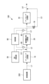
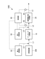
- FIG. 1 is a schematic configuration diagram showing an exhaust gas treatment device according to a first embodiment of the present disclosure.
- the exhaust gas treatment device 100 of the present embodiment includes an ammonia decomposition section (first treatment section) 10, a nitrogen oxide decomposition section (second treatment section) 20, and an ammonia decomposition section (third treatment section). part) 30, a detection part 40, a first supply part 50 that supplies ammonia or urea water as a reducing agent, a temperature sensor 60, a bypass valve 70, and a control part 80.
- the exhaust gas discharged from the combustion device 200 is supplied to the ammonia decomposition unit 10 via the pipe L1.
- the exhaust gas that has passed through the ammonia decomposition section 10 is supplied to the nitrogen oxide decomposition section 20 via the pipe L2.
- the exhaust gas that has passed through the nitrogen oxide decomposition section 20 is supplied to the ammonia decomposition section 30 via the pipe L3.
- the exhaust gas that has passed through the ammonia decomposition section 30 is discharged to the outside via the pipe L4.
- the exhaust gas treatment device 100 of the present embodiment includes the pipe L5 and the bypass valve 70, it may be a modified example that does not include these. In this modification, the entire amount of exhaust gas that has passed through the nitrogen oxide decomposition section 20 is guided to the ammonia decomposition section 30.
- the ammonia decomposition unit 10 has an ammonia decomposition catalyst (first catalyst) that decomposes ammonia contained in the exhaust gas discharged from the combustion device 200.
- the ammonia decomposition catalyst is a multifunctional catalyst that not only decomposes ammonia but also decomposes NOx and suppresses the production of nitrous oxide.
- the ammonia decomposition catalyst of this embodiment includes a first component that is silica and/or zeolite supporting one or more noble metals selected from platinum (Pt), palladium (Pd), iridium (Ir), and rhodium (Rh). , a second component which is a composition comprising an oxide of one or more elements selected from titanium (Ti), tungsten (W) and vanadium (V). Examples of the ammonia decomposition catalyst will be described later.
- the ammonia decomposition catalyst of the ammonia decomposition unit 10 decomposes NH 3 using the first component according to the following formulas (1) and (2).
- ammonia decomposition catalyst of the ammonia decomposition unit 10 decomposes NH 3 using the second component according to the following formula (3), and also removes at least a portion of NO by-produced according to the formula (2).
- nitrous oxide N 2 O
- the ammonia decomposition catalyst since a small amount of noble metal catalyst is uniformly present on the denitrification catalyst, the NO2 generated on the precious metal catalyst is immediately converted to the NO2 generated on the denitration catalyst together with the NO generated in formula (2). There is a high probability that the reaction will result in N2 , and therefore the by-product of N2O can be reduced.
- 4NH 3 +7O 2 ⁇ 4NO 2 +6H 2 O 4NH 3 +4NO 2 +O 2 ⁇ 4N 2 O+6H 2 O (5) NO+NO 2 +2NH 3 ⁇ 2N 2 +3H 2 O (6)
- the nitrogen oxide decomposition unit 20 has a nitrogen oxide decomposition catalyst (second catalyst) that decomposes nitrous oxide and NOx contained in the exhaust gas from which ammonia has been decomposed in the ammonia decomposition unit 10.
- the nitrogen oxide decomposition catalyst contains a carrier containing SiO 2 and Al 2 O 3 and an iron element supported thereon. In the carrier, SiO 2 and Al 2 O 3 may be contained as a mixture or as a composite.
- An example of a composite of SiO2 and Al2O3 is aluminosilicate ( xM2O.yAl2O3.zSiO2.nH2O ) . Examples of the nitrogen oxide decomposition catalyst will be described later.
- the nitrogen oxide decomposition catalyst of the nitrogen oxide decomposition unit 20 decomposes nitrous oxide by subjecting it to a reduction reaction with NH 3 according to the following equation (7).
- the nitrogen oxide decomposition catalyst of the nitrogen oxide decomposition unit 20 decomposes NOx by subjecting it to a reduction reaction with NH 3 according to the following equations (8), (9), and (10).
- 4NO+4NH 3 +O 2 ⁇ 4N 2 +6H 2 O (8) NO+NO 2 +2NH 3 ⁇ 2N 2 +3H 2 O (9) 6NO 2 +8NH 3 ⁇ 7N 2 +12H 2 O (10)
- the ammonia decomposition unit 30 has an ammonia decomposition catalyst (third catalyst) that decomposes ammonia contained in the exhaust gas that has passed through the nitrogen oxide decomposition unit 20.
- the ammonia decomposition catalyst is a multifunctional catalyst that not only decomposes ammonia but also decomposes NOx and suppresses the production of nitrous oxide.
- the ammonia decomposition catalyst includes a first component that is silica and/or zeolite supporting one or more noble metals selected from platinum (Pt), palladium (Pd), iridium (Ir), and rhodium (Rh), and a titanium (Ti ), and a second component which is a composition comprising an oxide of one or more elements selected from tungsten (W) and vanadium (V).
- the configuration of the ammonia decomposition unit 30 is similar to the configuration of the ammonia decomposition unit 10, so the description below will be omitted.
- the detection unit 40 is a device that detects the concentration of nitrous oxide and NOx contained in the exhaust gas that has passed through the ammonia decomposition unit 10.
- the detection unit 40 detects the concentrations of nitrous oxide and NOx contained in the exhaust gas passing through the pipe L3.
- the concentrations of nitrous oxide and NOx detected by the detection unit 40 are transmitted to the control unit 80.
- the first supply unit 50 is a device that supplies ammonia or urea water, which is a reducing agent, to the exhaust gas supplied from the ammonia decomposition unit 10 to the nitrogen oxide decomposition unit 20.
- the first supply unit 50 supplies the reducing agent to the pipe L2 via the pipe L6, and mixes it with the exhaust gas flowing through the pipe L2.
- the pipe L6 mixes the reducing agent with the exhaust gas by, for example, spraying the reducing agent into the pipe L2.
- the first supply unit 50 adjusts the amount of reducing agent supplied to the pipe L2 according to a control signal transmitted from the control unit 80.
- the urea water mixed with the exhaust gas in the pipe L2 is hydrolyzed in the exhaust gas to generate ammonia.
- the nitrogen oxide decomposition catalyst of the nitrogen oxide decomposition unit 20 decomposes NOx by causing a reduction reaction with ammonia (NH 3 ) according to the above-mentioned equations (7), (8), and (9).
- the temperature sensor 60 is a device that detects the temperature of exhaust gas flowing through the pipe L2.
- the temperature sensor 60 transmits the detected temperature of the exhaust gas to the control unit 80.
- the bypass valve 70 is an on-off valve disposed in the pipe L5.
- the open/close state of the bypass valve 70 is controlled by a control section 80.
- the bypass valve 70 When the bypass valve 70 is in the open state, exhaust gas is guided from the pipe L3 to the pipe L4 via the pipe L5.
- the bypass valve 70 When the bypass valve 70 is in the closed state, the exhaust gas is not guided to the pipe L5, and the entire amount of exhaust gas flowing through the pipe L3 is guided to the pipe L4 via the ammonia decomposition section 30.
- the control unit 80 is a device that controls each part of the exhaust gas treatment device 100.
- the control unit 80 controls each unit of the exhaust gas treatment device 100 by reading and executing a control program stored in a storage unit (not shown).
- the control unit 80 controls the amount of reducing agent supplied to the pipe L2 by the first supply unit 50 according to the concentration of nitrous oxide and NOx detected by the detection unit 40 and the temperature of the exhaust gas detected by the temperature sensor 60. do. Further, the control unit 80 controls the opening/closing state of the bypass valve 70 according to the concentration of nitrous oxide and NOx detected by the detection unit 40 and the temperature of exhaust gas detected by the temperature sensor 60.
- FIG. 2 is a graph showing the decomposition characteristics of an ammonia decomposition catalyst. As shown in FIG. 2, as the temperature of the exhaust gas containing ammonia rises from 350°C to 450°C, the ammonia decomposition rate [%] by the ammonia decomposition catalyst of the ammonia decomposition unit 10 increases.
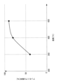
- FIG. 3 is a graph showing the relationship between ammonia concentration and temperature rise in an ammonia decomposition catalyst.
- the ammonia decomposition catalyst of the ammonia decomposition unit 10 increases the temperature of the exhaust gas as the concentration of unburned ammonia contained in the exhaust gas discharged from the combustion device 200 increases due to the heat generated when decomposing ammonia. The rise becomes larger.
- the temperature of the ammonia decomposition part 10 can be raised and the ammonia decomposition rate can be increased. Furthermore, the temperature of the exhaust gas discharged from the ammonia decomposition section 10 can be increased.
- FIG. 4 is a graph showing the decomposition characteristics of nitrous oxide with respect to the temperature of exhaust gas.
- Catalysts AF shown in FIG. 4 correspond to catalysts AF described in Examples of nitrogen oxide decomposition catalysts described later.
- the decomposition rate of nitrous oxide increases as the exhaust gas temperature increases. Therefore, when the ammonia decomposition catalyst of the ammonia decomposition unit 10 decomposes ammonia and raises the temperature of the exhaust gas, the decomposition rate of nitrous oxide increases as the temperature of the exhaust gas increases.
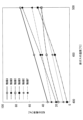
- FIG. 5 is a graph showing the NO decomposition characteristics with respect to exhaust gas temperature.
- Catalysts AF shown in FIG. 5 correspond to catalysts AF described in Examples of nitrogen oxide decomposition catalysts described later.
- the NO decomposition rate increases as the exhaust gas temperature increases. Therefore, when the ammonia decomposition catalyst of the ammonia decomposition unit 10 decomposes ammonia and raises the temperature of the exhaust gas, the NO decomposition rate increases as the temperature of the exhaust gas increases.
- the ammonia decomposition unit 10 is installed upstream of the nitrogen oxide decomposition unit 20 because the amount of unburned ammonia supplied in the exhaust gas discharged from the combustion device 200 is This is because it is assumed that the amount of ammonia exceeds the amount required for decomposing nitrous oxide and NOx in the decomposition unit 20.
- the exhaust gas treatment device 100 of this embodiment decomposes excess ammonia in the ammonia decomposition unit 10, increases the temperature of the exhaust gas by the heat generated when ammonia is decomposed, and reduces nitrous oxide and NOx in the nitrogen oxide decomposition unit 20. Increases decomposition rate.
- the exhaust gas treatment device 100 of this embodiment assumes that the concentrations of ammonia, nitrous oxide, and NOx contained in the exhaust gas discharged from the combustion device 200 satisfy the following equation (11). Ammonia concentration > ⁇ ⁇ nitrous oxide concentration + ⁇ ⁇ NOx concentration (11)
- the numerical values by which ⁇ and ⁇ are multiplied are not limited to 1.5, and may be set to any numerical value greater than or equal to 1.2 and less than or equal to 2.0, for example, depending on the properties of the exhaust gas from the combustion device 200.
- the reducing agent is supplied from the first supply section 50 to reduce ammonia in the nitrogen oxide decomposition section 20. Make up for the shortage.
- FIG. 6 is a flowchart showing the reducing agent supply process in the exhaust gas treatment apparatus 100 of this embodiment.
- the processing of each step in FIG. 6 is executed by the control section 80 controlling each section of the exhaust gas treatment apparatus 100.
- the process of this flowchart is started in response to the start of the combustion operation by the combustion device 200.
- step S101 the control unit 80 determines that the temperature Ta of the exhaust gas flowing through the pipe L2 transmitted from the temperature sensor 60 is equal to or higher than the supply temperature (for example, 350° C.) at which the reducing agent can be supplied to the nitrogen oxide decomposition unit 20. It is determined whether or not there is, and if YES, the process proceeds to step S102, and if NO, the process proceeds to step S108.
- the supply temperature for example, 350° C.
- step S108 the control unit 80 controls the first supply unit 50 to supply the reducing agent because the temperature Ta of the exhaust gas flowing through the pipe L2 is lower than the supply temperature at which the reducing agent can be supplied to the nitrogen oxide decomposition unit 20. control to stop.
- step S102 the control unit 80 determines whether the NOx concentration detected by the detection unit 40 is below a first predetermined concentration (for example, 200 ppm), and if YES, the process proceeds to step S103; If so, the process advances to step S105.
- a first predetermined concentration for example, 200 ppm
- step S103 the control unit 80 determines whether the nitrous oxide concentration detected by the detection unit 40 is equal to or lower than a second predetermined concentration (for example, 50 ppm), and if YES, the process proceeds to step S104, and if NO If so, the process advances to step S105.
- a second predetermined concentration for example, 50 ppm
- step S104 the control unit 80 determines that since the NOx concentration is the first predetermined concentration or less and the nitrous oxide concentration is the second predetermined concentration or less, the reduction process of NOx and nitrous oxide by ammonia is appropriately performed. It is determined that the supply amount of the reducing agent is reduced, and the first supply unit 50 is controlled to reduce the supply amount of the reducing agent.
- step S105 the control unit 80 determines that because the NOx concentration is higher than the first predetermined concentration or the nitrous oxide concentration is higher than the second predetermined concentration, the reduction process of NOx and nitrous oxide by ammonia is not sufficiently performed. It is determined that the first supply unit 50 is increased to increase the reducing agent supply amount, and the process proceeds to step S101.
- step S106 the control unit 80 determines whether the combustion device 200 is stopped, and if the determination is YES, the process proceeds to step S107, and if the determination is NO, the control unit 80 executes step S101 again.
- Combustion device 200 transmits operating states, including a state in which combustion operation is stopped, to control unit 80.
- step S107 the control unit 80 determines that the reduction treatment of NOx and nitrous oxide using ammonia is unnecessary because the combustion device 200 is stopped, and causes the first supply unit 50 to stop supplying the reducing agent. , the process of this flowchart ends. The control unit 80 restarts the process of this flowchart when the combustion device 200 starts the combustion operation.
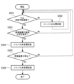
- FIG. 7 is a flowchart showing switching processing of the bypass valve 70 in the exhaust gas treatment device 100 of this embodiment.
- the processing of each step in FIG. 7 is executed by the control section 80 controlling each section of the exhaust gas treatment apparatus 100.
- the process of this flowchart is started in response to the start of the combustion operation by the combustion device 200.
- the exhaust gas treatment device 100 of this embodiment has an ammonia decomposition unit 30 disposed downstream of the nitrogen oxide decomposition unit 20.
- the ammonia decomposition unit 30 is configured to remove surplus This is provided to ensure that the ammonia is decomposed and not discharged to the outside.
- the ammonia decomposition unit 30 does not need to process the exhaust gas in the ammonia decomposition unit 30, When the exhaust gas passes through the ammonia decomposition section 30, a pressure loss is caused. Therefore, in this embodiment, when the concentration of ammonia contained in the exhaust gas discharged from the nitrogen oxide decomposition unit 20 is below a predetermined permissible concentration, a part of the exhaust gas discharged from the nitrogen oxide decomposition unit 20 is By guiding the exhaust gas to the pipe L5, pressure loss is prevented from occurring when the exhaust gas passes through the ammonia decomposition section 30.
- step S201 the control unit 80 determines that the temperature Ta of the exhaust gas flowing through the pipe L2 transmitted from the temperature sensor 60 is equal to or higher than the supply temperature (for example, 350° C.) at which the reducing agent can be supplied to the nitrogen oxide decomposition unit 20. It is determined whether or not there is, and if YES, the process proceeds to step S203, and if NO, the process proceeds to step S202.
- the supply temperature for example, 350° C.
- step S202 the control unit 80 determines that the temperature Ta of the exhaust gas flowing through the pipe L2 is lower than the supply temperature at which the reducing agent can be supplied to the nitrogen oxide decomposition unit 20, and the temperature of the exhaust gas discharged from the combustion device 200 is Since the temperature has not risen to an appropriate level, the bypass valve 70 is controlled to be closed.
- step S203 the control unit 80 determines whether the load of the combustion device 200 is below a predetermined load (for example, 50% load), and if the determination is YES, the process proceeds to step S204, and if the determination is NO. If so, step S201 is executed again.
- Combustion device 200 transmits the load of combustion operation to control unit 80 .
- step S204 the control unit 80 controls the bypass valve 70 to open because the load on the combustion device 200 is less than or equal to the predetermined load.
- the concentration of ammonia contained in the exhaust gas discharged from the nitrogen oxide decomposition unit 20 is below a predetermined permissible concentration (for example, 5 ppm), and the exhaust gas is removed by the ammonia decomposition unit 30. No need to process. Therefore, in order to reduce the pressure loss caused when the exhaust gas passes through the ammonia decomposition section 30, a part of the exhaust gas flowing through the pipe L3 is guided from the pipe L5 to the pipe L4.
- step S205 the control unit 80 determines whether the combustion device 200 is stopped, and if the determination is YES, the process proceeds to step S206, and if the determination is NO, the control unit 80 executes step S201 again.
- Combustion device 200 transmits operating states, including a state in which combustion operation is stopped, to control unit 80.
- step S206 since the combustion device 200 is stopped, the control unit 80 closes the bypass valve 70 and ends the process of this flowchart. The control unit 80 restarts the process of this flowchart when the combustion device 200 starts the combustion operation.
- the detection unit 40 detects the concentrations of nitrous oxide and NOx contained in the exhaust gas that has passed through the ammonia decomposition unit 10, but other embodiments may be used.
- the detection unit 40 may detect the concentration of either nitrous oxide or NOx contained in the exhaust gas that has passed through the ammonia decomposition unit 10.
- the detection unit 40 detects the concentration of nitrous oxide
- the process of step S102 in FIG. 6 is omitted.
- the detection unit 40 detects the concentration of NOx
- the process of step S103 in FIG. 6 is omitted.
- ammonia decomposition catalyst of the ammonia decomposition unit 10 of this embodiment can be obtained, for example, by any of the following examples.
- Example 1 100 g of fine silica powder (manufactured by Tomita Pharmaceutical Co., Ltd., silicic anhydride) was added to 1 liter of 1.33 ⁇ 10 -2 wt% chloroplatinic acid (H 2 [PtCl 6 ].6H 2 O) aqueous solution, and the mixture was poured on a sand bath. The mixture was evaporated to dryness and calcined in air at 500° C. for 2 hours to prepare 0.05 wt% Pt.SiO 2 to obtain a catalyst composition powder as the first component.
- chloroplatinic acid H 2 [PtCl 6 ].6H 2 O
- ammonium paratungstate (NH 4 ) 10.W 12 O 41.5H 2 O) 7 .
- 43 kg of ammonium metavanadate and 3.0 kg of ammonium metavanadate were added and kneaded using a kneader, and the resulting paste was granulated, dried, and fired at 550° C. for 2 hours.
- the obtained granules were crushed to obtain catalyst composition powder as the second component.
- a slurry obtained by suspending 20 g of the first component and 2.02 kg of the second component in 3.06 kg of water is coated with a paper honeycomb carrier (manufactured by Nichias Corporation, trade name, Honeycle 3722, 150 mm x 150 mm square, length 50 mm). After the carrier was impregnated with the slurry by immersion, the liquid was removed by air blowing to obtain the catalyst of this example. This was air-dried in the atmosphere for 12 hours and then fired at 500°C for 2 hours.
- the first component/second component ratio of the first component and the second component in this catalyst is 1/99 (weight ratio, same hereinafter), the Pt content in the catalyst component is equivalent to 5 ppm, and the catalyst is supported.
- the amount of the first and second components together was 150 g/m 2 per carrier surface area.
- a test piece with a length of 50 mm and a size of 5 stages x 8 cells (11 x 14 mm) was cut out from the obtained honeycomb catalyst.
- Example 2 A catalyst of this example was obtained in the same manner as in Example 1 except that the first component was changed to 10 g, the second component was changed to 2.02 kg, and the water was changed to 3.04 kg.
- the first component/second component ratio of the first component and the second component in this catalyst is 0.5/99.5, the Pt content in the catalyst component is equivalent to 2.5 ppm, and the supported amount of the catalyst is
- the total amount of the first and second components was 150 g/m 2 per carrier surface area.
- Example 3-5 Using the first component and second component obtained in Example 1, the amount of water added during slurry preparation was changed to 476 and 816 kg, and the resulting slurry was transferred to a paper honeycomb carrier (manufactured by Nichias Co., Ltd., trade name, Honeycle 3319, The catalyst of this example was obtained by supporting the catalyst on a 150 mm x 150 mm square and 50 mm length in the same manner as in Example 1. The first component/second component ratio of the first component and the second component in this catalyst was 1/99, and the Pt content in the catalyst component was equivalent to 5 ppm. The supported amounts of the catalyst in Example 3-5 were 100, 80, and 50 g/m 2 per carrier surface area, including the first component and the second component, respectively.
- Example 6 A catalyst of this example was obtained in the same manner as in Example 1 except that the paper honeycomb carrier of Example 1 was changed to a metal lath (SUS304, plate thickness 0.2 mm, 150 mm x 150 mm square). The first component/second component ratio of the first component and the second component in this catalyst was 1/99, and the Pt content in the catalyst component was equivalent to 5 ppm. The amount of catalyst supported was 200 g/m 2 per surface area of the carrier, including the first component and the second component.
- a metal lath SUS304, plate thickness 0.2 mm, 150 mm x 150 mm square
- the nitrogen oxide decomposition catalyst of the nitrogen oxide decomposition unit 20 of this embodiment is, for example, any of the following catalysts A to E.
- iron (III) nitrate nonahydrate Fe 2 (NO 3 ) 3.9H 2 O
- This powder was added to 2000 ml of an aqueous solution containing 13.2 g of iron(III) nitrate nonahydrate (Fe 2 (NO 3 ) 3.9H 2 O), and the above operation was repeated two more times (3 ion exchange steps in total). ) to obtain powdered Fe-supported zeolite catalyst D.
- Honeycomb catalyst D was obtained by the same manufacturing method as catalyst A except that Fe-supported zeolite catalyst A was replaced with Fe-supported zeolite catalyst D.
- the exhaust gas treatment device 100 According to the exhaust gas treatment device 100 according to the present disclosure, ammonia contained in the exhaust gas discharged from the combustion device 200 is appropriately decomposed by the ammonia decomposition catalyst when passing through the ammonia decomposition section 10. Further, nitrous oxide and NOx generated when ammonia is burned in the combustion device 200 are appropriately decomposed by the nitrogen oxide decomposition catalyst when passing through the nitrogen oxide decomposition section 20. In this manner, the exhaust gas treatment device 100 according to the present disclosure can appropriately decompose ammonia and nitrous oxide contained in the exhaust gas discharged from the combustion device 200 that burns fuel containing ammonia.
- the exhaust gas treatment device 100 of the present embodiment even if ammonia remains in the exhaust gas that has passed through the nitrogen oxide decomposition unit 20, the ammonia is decomposed in the ammonia decomposition unit 30, so that ammonia is removed from the outside. can be prevented from being discharged.
- the concentration of nitrous oxide contained in the exhaust gas that has passed through the nitrogen oxide decomposition section 20 is higher than the first predetermined concentration, or the concentration of nitrous oxide contained in the exhaust gas that has passed through the nitrogen oxide decomposition section 20 is
- the detection unit 40 detects that the concentration of NOx contained is higher than the second predetermined concentration
- the NOx is supplied to the nitrogen oxide decomposition unit 20 to compensate for the lack of ammonia for reducing nitrous oxide and NOx.
- a reducing agent is supplied to the exhaust gas from the first supply section 50.
- the shortage of ammonia supplied from the ammonia decomposition unit 10 to the nitrogen oxide decomposition unit 20 is compensated for, and the concentration of nitrous oxide and NOx contained in the exhaust gas that has passed through the nitrogen oxide decomposition unit 20 is reduced. Can be done.
- the exhaust gas treatment device 100A of the present embodiment is a modification of the exhaust gas treatment device 100 of the first embodiment, and is the same as the first embodiment except when specifically explained below. Omitted.
- the exhaust gas treatment device 100B of the present embodiment is different from the first embodiment in that it includes a pipe (bypass pipe) L7 that guides a part of the exhaust gas flowing through the pipe L1 to the pipe L2, and a bypass valve 90 disposed in the pipe L7. This is different from the exhaust gas treatment device 100.
- FIG. 8 is a schematic configuration diagram showing an exhaust gas treatment device 100A according to the second embodiment of the present disclosure.
- the exhaust gas treatment device 100A of this embodiment includes a pipe L7 that guides a part of the exhaust gas flowing through the pipe L1 to the pipe L2, and a bypass valve 90 arranged in the pipe L7.
- the bypass valve 90 is an on-off valve arranged in the pipe L7.
- the opening/closing state of the bypass valve 90 is controlled by the control section 80.
- the bypass valve 90 When the bypass valve 90 is in the open state, exhaust gas is guided from the pipe L1 to the pipe L2 via the pipe L7.
- the bypass valve 90 When the bypass valve 90 is in the closed state, the exhaust gas is not guided to the pipe L7, and the entire amount of exhaust gas flowing through the pipe L1 is guided to the pipe L2 via the ammonia decomposition unit 10.
- the supply amount of unburned ammonia contained in the exhaust gas discharged from the combustion device 200 is the amount of ammonia necessary for decomposing nitrous oxide and NOx in the nitrogen oxide decomposition unit 20. If the amount exceeds , the bypass valve 90 is closed, the entire amount of exhaust gas flowing through the pipe L1 is guided to the ammonia decomposition section 10, and the excess ammonia is decomposed in the ammonia decomposition section 10.
- the supply amount of unburned ammonia contained in the exhaust gas discharged from the combustion device 200 is necessary for decomposing nitrous oxide and NOx in the nitrogen oxide decomposition unit 20.
- the bypass valve 90 is opened and a part of the exhaust gas flowing through the pipe L1 is guided to the pipe L2 without passing through the ammonia decomposition section 10.
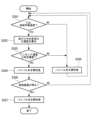
- FIG. 9 is a flowchart showing switching processing of the bypass valve 90 of the exhaust gas treatment device 100A according to the present embodiment.
- the processing of each step in FIG. 9 is executed by the control unit 80 controlling each part of the exhaust gas treatment apparatus 100A.
- the process of this flowchart is started in response to the start of the combustion operation by the combustion device 200.
- step S301 the control unit 80 determines that the temperature Ta of the exhaust gas flowing through the pipe L2, which is transmitted from the temperature sensor 60, is equal to or higher than the supply temperature (for example, 350° C.) at which the reducing agent can be supplied to the nitrogen oxide decomposition unit 20. It is determined whether or not there is, and if YES, the process proceeds to step S302, and if NO, the process proceeds to step S305.
- the supply temperature for example, 350° C.
- step S302 the control unit 80 calculates the concentration of each component of ammonia, nitrous oxide, and NOx in the exhaust gas discharged from the combustion device 200 based on the load of the combustion device 200.
- Combustion device 200 transmits the load of combustion operation to control unit 80 .
- the control unit 80 stores in a storage unit (not shown) a map of the concentration of each component of ammonia, nitrous oxide, and NOx, which is associated with each of the plurality of loads of the combustion device 200.
- the control unit 80 calculates the concentration associated with the load transmitted from the combustion device 200 with reference to the map stored in the storage unit.
- step S303 the control unit 80 determines whether the ammonia concentration calculated in step S302 is below a predetermined concentration, and if YES, the process proceeds to step S304, and if NO, the process proceeds to step S305.
- the predetermined concentration is the concentration expressed by the following equation (12).
- step S304 the control unit 80 controls the bypass valve 90 because the ammonia concentration is below the predetermined concentration and there is no need to supply the entire amount of exhaust gas to the ammonia decomposition unit 10 in order to decompose excess ammonia in the ammonia decomposition unit 10. Open.
- step S305 the control unit 80 closes the bypass valve 90 because the exhaust gas temperature Ta is lower than the supply temperature at which the reducing agent can be supplied to the nitrogen oxide decomposition unit 20, or the ammonia concentration is higher than the predetermined concentration. state. This is because the temperature of the exhaust gas discharged from the combustion device 200 is not high enough, or the ammonia concentration contained in the exhaust gas is higher than the predetermined concentration, so it is necessary to supply the entire amount of the exhaust gas to the ammonia decomposition unit 10. It is.
- step S306 the control unit 80 determines whether the combustion device 200 is stopped, and if the determination is YES, the process proceeds to step S307, and if the determination is NO, the control unit 80 executes step S301 again.
- Combustion device 200 transmits operating states, including a state in which combustion operation is stopped, to control unit 80.
- step S307 since the combustion device 200 is stopped, the control unit 80 closes the bypass valve 90, and ends the process of this flowchart. The control unit 80 restarts the process of this flowchart when the combustion device 200 starts the combustion operation.
- the concentration of ammonia contained in the exhaust gas discharged from the combustion device 200 is the concentration required as a reducing agent when decomposing nitrous oxide and NOx in the nitrogen oxide decomposition unit 20. If the value is higher than , excess ammonia can be decomposed by the ammonia decomposition unit 10 by closing the bypass valve 90 .
- the concentration of ammonia contained in the exhaust gas discharged from the combustion device 200 is the same as or lower than the concentration required as a reducing agent when decomposing nitrous oxide and NOx in the nitrogen oxide decomposition unit 20, By opening the bypass valve 90, ammonia can be guided to the nitrogen oxide decomposition unit 20 without being decomposed in the ammonia decomposition unit 10.
- the exhaust gas treatment device 100B of the present embodiment is a modification of the exhaust gas treatment device 100 of the first embodiment, and is the same as the first embodiment except when specifically explained below. Omitted.
- the exhaust gas treatment device 100 of the first embodiment had the ammonia decomposition unit 10 disposed upstream of the nitrogen oxide decomposition unit 20.
- the exhaust gas treatment device 100B of this embodiment does not include the ammonia decomposition unit 10 upstream of the nitrogen oxide decomposition unit 20.
- FIG. 10 is a schematic configuration diagram showing an exhaust gas treatment device 100B according to a third embodiment of the present disclosure.
- the exhaust gas treatment device 100B of this embodiment does not include the ammonia decomposition unit 10 upstream of the nitrogen oxide decomposition unit 20, and the exhaust gas discharged from the combustion device 200 is The nitrogen oxides are supplied to the nitrogen oxide decomposition unit 20 via the nitrogen oxide decomposition unit 20.
- the ammonia decomposition unit 10 is not installed upstream of the nitrogen oxide decomposition unit 20 because the amount of unburned ammonia supplied in the exhaust gas discharged from the combustion device 200 is This is because it is assumed that the amount of ammonia required to decompose nitrous oxide and NOx in the decomposition unit 20 is equal to or less than that.
- the exhaust gas treatment device 100B of this embodiment makes up for the shortage of ammonia necessary as a reducing agent for decomposing nitrous oxide and NOx contained in the exhaust gas by supplying it from the first supply unit 50.
- the exhaust gas treatment device 100B of this embodiment assumes that the concentrations of ammonia, nitrous oxide, and NOx contained in the exhaust gas discharged from the combustion device 200 satisfy the following equation (13).
- ⁇ and ⁇ are coefficients, which are the same as those explained in equation (11) of the first embodiment.
- the reducing agent supply process in the exhaust gas treatment device 100B of this embodiment is similar to the process shown in FIG. 6 of the first embodiment.
- the switching process of the bypass valve 70 in the exhaust gas treatment apparatus 100A of this embodiment is similar to the process shown in FIG. 7 of the first embodiment.
- the exhaust gas treatment device 100B of this embodiment The functions and effects of the exhaust gas treatment device 100B of this embodiment described above will be explained.
- ammonia contained in the exhaust gas discharged from the combustion device 200 is converted into nitrous oxide and nitrous oxide as a reducing agent by the nitrogen oxide decomposition catalyst when passing through the nitrogen oxide decomposition unit 20. Decomposed by reacting with NOx. Further, nitrous oxide and NOx generated when ammonia is burned in the combustion device 200 are appropriately decomposed by the nitrogen oxide decomposition catalyst when passing through the nitrogen oxide decomposition section 20.
- the exhaust gas treatment device 100B of the present embodiment can appropriately decompose ammonia, nitrous oxide, and NOx contained in the exhaust gas discharged from the combustion device 200 that burns fuel containing ammonia.
- the design method of this embodiment includes a design in which the ammonia decomposition unit 10 is disposed upstream of the nitrogen oxide decomposition unit 20 as in the exhaust gas treatment apparatuses 100 and 100A described in the first embodiment and the second embodiment, and This is a method of determining which design to perform, a design in which the ammonia decomposition unit 10 is not disposed on the upstream side of the nitrogen oxide decomposition unit 20, like the exhaust gas treatment device 100B described in the third embodiment.
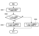
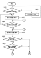
- FIG. 11 is a flowchart showing a method for designing an exhaust gas treatment device according to this embodiment.
- step S401 the concentration of each component of ammonia, nitrous oxide, and NOx in the exhaust gas discharged from the combustion device 200 is calculated.
- the concentration of each component is determined by assuming that the combustion device 200 operates at a predetermined constant load, and specifying the concentration of each component of ammonia, nitrous oxide, and NOx in the exhaust gas at that load.
- step S402 it is determined whether the ammonia concentration calculated in step S401 is below a predetermined concentration, and if YES, the process proceeds to step S403, and if NO, the process proceeds to step S404.
- the predetermined concentration is the concentration expressed by equation (12) of the second embodiment, which is ⁇ nitrous oxide concentration+ ⁇ NOx concentration.
- step S403 since the ammonia concentration in the exhaust gas discharged from the combustion device 200 is below the predetermined concentration, the exhaust gas treatment device 100B of the third embodiment does not dispose the ammonia decomposition unit 10 upstream of the nitrogen oxide decomposition unit 20.
- the design shall be as follows. The reason for this design is that there is no need to dispose the ammonia decomposition section 10 upstream of the nitrogen oxide decomposition section 20 to decompose excess ammonia.
- step S404 since the ammonia concentration in the exhaust gas discharged from the combustion device 200 is higher than the predetermined concentration, the exhaust gas treatment device 100 of the first embodiment or This is a design of an exhaust gas treatment device 100A of the second embodiment.
- the reason for this design is that since the ammonia concentration contained in the exhaust gas is higher than a predetermined concentration, it is necessary to supply the entire amount of the exhaust gas to the ammonia decomposition unit 10 to decompose excess ammonia.
- the concentration of ammonia contained in the exhaust gas is equal to the first concentration obtained by multiplying the concentration of nitrous oxide contained in the exhaust gas by ⁇ (first coefficient). If the concentration of ammonia supplied from the ammonia decomposition unit 10 to the nitrogen oxide decomposition unit 20 is higher than the total concentration of the second concentration obtained by multiplying the NOx concentration by ⁇ (second coefficient), the concentration of ammonia supplied from the ammonia decomposition unit 10 to the nitrogen oxide decomposition unit 20 becomes excessive.
- the exhaust gas treatment device is designed so that the ammonia decomposition section 10 is disposed downstream of the combustion device 200, and the nitrogen oxide decomposition section 20 is disposed downstream of the ammonia decomposition section 10.
- the concentration of ammonia contained in the exhaust gas is calculated by multiplying the concentration of nitrous oxide contained in the exhaust gas by ⁇ (first coefficient), and the concentration of NOx contained in the exhaust gas multiplied by ⁇ (second coefficient). If the concentration is lower than the total concentration with the second concentration, the concentration of ammonia supplied from the ammonia decomposition unit 10 to the nitrogen oxide decomposition unit 20 will not become excessive.
- the exhaust gas treatment device is designed so that the nitrogen oxide decomposition section 20 is arranged without the nitrogen oxide decomposition section 10. Thereby, it is possible to design an exhaust gas treatment device having an appropriate configuration according to the concentration of ammonia contained in the exhaust gas discharged from the combustion device 200.
- the exhaust gas treatment device 100C of the present embodiment is a modification of the exhaust gas treatment device 100 of the first embodiment, and is the same as the first embodiment except when specifically explained below. Omitted.
- the exhaust gas treatment device 100C of this embodiment uses ammonia or urea water as a fuel for heating the ammonia decomposition catalyst (first treatment section) of the ammonia decomposition section 10 in the exhaust gas supplied from the combustion device 200 to the ammonia decomposition section 10. This differs from the exhaust gas treatment device 100 of the first embodiment in that it includes a second supply section 55 that supplies . Further, the exhaust gas treatment device 100C of this embodiment differs from the exhaust gas treatment device 100 of the first embodiment in that it does not include the ammonia decomposition unit 30.
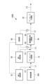
- FIG. 12 is a schematic configuration diagram showing an exhaust gas treatment device 100C according to the present embodiment.
- the exhaust gas treatment device 100C of this embodiment includes an ammonia decomposition unit (first treatment unit) 10, a nitrogen oxide decomposition unit (second treatment unit) 20, a detection unit 40, and a first It includes a supply section 50, a second supply section 55, a temperature sensor 60, and a control section 80.
- the other configurations except for the second supply section 55 are the same as those in the first embodiment, so the description below will be omitted.
- the second supply unit 55 supplies ammonia or This is a device that supplies urea water.
- the second supply unit 55 supplies urea water to the pipe L1 via the pipe L8, and generates ammonia through a hydrolysis reaction of the urea water.
- Ammonia guided to the ammonia decomposition unit 10 is decomposed by the action of the ammonia decomposition catalyst according to the reactions of formulas (1) and (2) of the first embodiment. Due to the exothermic reaction when ammonia is decomposed, the exhaust gas passing through the ammonia decomposition section 10 is heated. Furthermore, instead of supplying urea water from the second supply section 55, ammonia may be supplied from the second supply section 55 to the pipe L2.
- the inventors conducted an experiment to confirm the relationship between the properties of the exhaust gas discharged from the combustion device 200 and the decomposition rate of nitrous oxide, and found that the decomposition rate of nitrous oxide changes depending on the concentration of NO contained in the exhaust gas. We obtained the knowledge that there is a temperature range where this occurs. If the decomposition rate of nitrous oxide changes depending on the concentration of NO contained in the exhaust gas, there is a possibility that the desired decomposition rate of nitrous oxide cannot be obtained in the exhaust gas treatment device 100 of the first embodiment. Therefore, in the exhaust gas treatment apparatus 100C of this embodiment, the nitrogen oxide decomposition unit 20 is operated in a temperature range in which the decomposition rate of nitrous oxide does not change depending on the concentration of NO contained in the exhaust gas.
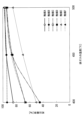
- FIG. 13 is a graph showing the decomposition rate of nitrous oxide with respect to the temperature of the exhaust gas in the nitrogen oxide decomposition unit 20, comparing the cases where the NO concentration is 0 ppm and the case where it is 450 ppm.
- FIG. 13 shows an example in which catalyst A is used as the nitrogen oxide decomposition catalyst in the nitrogen oxide decomposition section 20.
- the example shown by the solid line and the example shown by the dotted line in FIG. 13 differ in that the NO concentration in the exhaust gas is 450 ppm and 0 ppm.
- the nitrous oxide concentration in the exhaust gas is 180 ppm
- the ammonia concentration in the exhaust gas is 570 ppm
- the oxygen concentration in the exhaust gas is 13%. They have in common that the sulfur dioxide concentration in the exhaust gas is 15 ppm, the moisture concentration in the exhaust gas is 15%, and the remainder is nitrogen.
- FIG. 13 shows the above-mentioned tendency is that the oxygen bound to the nitrogen oxide decomposition catalyst in the following formula (11) is lower than 450°C, while the oxygen bound to the nitrogen oxide decomposition catalyst in formula (12) is This is presumed to be because nitrous oxide was removed and/or reduced by the reaction of formula (13). That is, it is presumed that this is because the decomposition rate of nitrous oxide becomes higher when NO in the exhaust gas exists together with nitrous oxide.
- the inventors set the temperature of the exhaust gas discharged from the ammonia decomposition unit 10 so that the decomposition rate of nitrous oxide would not change depending on the concentration of NO contained in the exhaust gas.
- the temperature range was set so that the temperature was 450°C or higher. Further, the inventors set a temperature range such that the temperature of the exhaust gas discharged from the ammonia decomposition unit 10 is 530° C. or lower in order to reduce thermal stress on the catalytic reactor and suppress thermal deterioration of the catalyst.
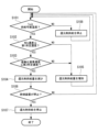
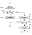
- 14 to 16 are flowcharts showing fuel and reducing agent supply processing in the exhaust gas treatment device 100C according to the present embodiment.
- the processing of each step in FIGS. 14 to 16 is executed by the control unit 80 controlling each part of the exhaust gas treatment apparatus 100C.
- the process of this flowchart is started in response to the start of the combustion operation by the combustion device 200.
- step S401 the control unit 80 determines that the temperature Ta of the exhaust gas flowing through the pipe L2 transmitted from the temperature sensor 60 is such that the fuel for heating the ammonia decomposition catalyst (first processing unit) is replaced with ammonia from the second supply unit 55. It is determined whether the temperature is higher than the temperature at which fuel can be supplied to the decomposition unit 10 (for example, 300° C.), and if YES, the process proceeds to step S402, and if NO, the process proceeds to step S403.
- step S402 the control unit 80 controls the second supply unit 55 to increase the amount of fuel supplied from the second supply unit 55 to the pipe L1.
- step S402 is executed for the first time after step S401, the amount of fuel supplied by the second supply section 55 is increased from 0 to a predetermined amount of supply.
- step S403 the control unit 80 stops the second supply unit 55 from supplying fuel because the temperature Ta of the exhaust gas flowing through the pipe L1 is lower than the temperature at which fuel can be supplied to the ammonia decomposition unit 10. control like this.
- step S404 the control unit 80 determines whether the temperature Ta of the exhaust gas is equal to or higher than the reducing agent supply temperature (for example, 450° C.) at which the reducing agent can be supplied to the nitrogen oxide decomposition unit 20, and if YES is determined. If the answer is NO, the process advances to step S402 and the amount of fuel supplied from the second supply section 55 is increased.
- the reducing agent supply temperature for example, 450° C.
- step S405 the control unit 80 controls the first supply unit 50 to increase the amount of reducing agent supplied from the first supply unit 50 to the pipe L2.
- step S405 is executed for the first time after step S404, the amount of reducing agent supplied by the first supply unit 50 is increased from 0 to a predetermined amount of supply.
- step S406 the control unit 80 determines whether the NOx concentration detected by the detection unit 40 is equal to or lower than a first predetermined concentration (for example, 200 ppm), and if YES, the process proceeds to step S407; If so, the process advances to step S414.
- a first predetermined concentration for example, 200 ppm
- step S407 the control unit 80 determines whether the nitrous oxide concentration detected by the detection unit 40 is equal to or lower than a second predetermined concentration (for example, 10 ppm), and if YES, the process proceeds to step S408, and if NO If so, the process advances to step S414.
- a second predetermined concentration for example, 10 ppm
- step S408 the control unit 80 controls the combustion device 200 to release the load restriction on the combustion device 200.
- the control unit 80 controls the combustion device 200 to have a predetermined load or less until the load restriction is canceled in this step. This is because the reducing agent supplied from the first supply section 50 to the nitrogen oxide decomposition section 20 is reduced in order to reduce the NOx concentration and the nitrous oxide concentration when the combustion device 200 is operated without limiting the load. This is because if the supply amount becomes excessive, unreacted ammonia may be discharged from the nitrogen oxide decomposition unit 20 to the outside via the pipe L3.
- unreacted ammonia is discharged from the nitrogen oxide decomposition unit 20 to the outside via the pipe L3 by controlling the combustion device 200 so that the load is below a predetermined value.
- the NOx concentration and nitrous oxide concentration can be made below the threshold value, and the environmental load can be reduced.
- step S409 the control unit 80 determines whether the temperature Ta is lower than or equal to the first upper limit temperature (for example, 480° C.), and if YES, the process proceeds to step S410, and if NO, the process proceeds to step S411. proceed.
- the first upper limit temperature for example, 480° C.
- step S410 the control unit 80 reduces the amount of fuel supplied from the second supply unit 55 to the pipe L1 so that the temperature Ta is below the first upper limit temperature. After executing step S410, the control unit 80 advances the process to step S404.
- step S411 since the temperature Ta is lower than the first upper limit temperature, the control unit 80 reduces the amount of reducing agent supplied from the first supply unit 50 to the pipe L2 and advances the process to step S412.
- step S412 the control unit 80 determines whether the combustion device 200 is stopped, and if the determination is YES, the process proceeds to step S413, and if the determination is NO, the control unit 80 executes step S404 again.
- Combustion device 200 transmits operating states, including a state in which combustion operation is stopped, to control unit 80.
- step S413 since the combustion device 200 is stopped, the control unit 80 stops the supply of reducing agent by the first supply unit 50 and the supply of fuel by the second supply unit 55, and ends the process of this flowchart. do.
- the control unit 80 restarts the process of this flowchart when the combustion device 200 starts the combustion operation.
- step S414 the control unit 80 calculates the amount of reducing agent required to reduce NOx and nitrous oxide based on the NOx concentration and nitrous oxide concentration calculated in step S302 of FIG. It is determined whether the amount of reducing agent being supplied is greater than the amount obtained by multiplying the required amount of reducing agent by a predetermined coefficient ⁇ , and if YES, the process proceeds to step S415, and if NO, the process proceeds to step S405. Proceed.
- the predetermined reducing agent supply amount is the supply amount obtained by multiplying the reducing agent amount necessary to reduce NOx and nitrous oxide included in the total nitrogen oxide concentration by a predetermined coefficient ⁇ .
- the coefficient ⁇ is set, for example, to a value of 0.8 or more and 1.2 or less.
- step S415 the control unit 80 determines whether the temperature Ta is equal to or lower than the second upper limit temperature (for example, 530° C.), and if YES, the process proceeds to step S416, and if NO, the process proceeds to step S417. proceed.
- the second upper limit temperature for example, 530° C.
- step S416 the control unit 80 increases the amount of fuel supplied from the second supply unit 55 to the pipe L1. After executing step S416, the control unit 80 advances the process to step S419.
- step S417 the control unit 80 reduces the amount of fuel supplied from the second supply unit 55 to the pipe L1 so that the temperature Ta becomes lower than the second upper limit temperature.
- step S4108 the control unit 80 reduces the output of the combustion device 200 (for example, reduces the load by 10%), and advances the process to step S404.
- step S419 the control unit 80 determines whether the combustion device 200 is stopped, and if the determination is YES, the process proceeds to step S420, and if the determination is NO, the control unit 80 executes step S405 again.
- Combustion device 200 transmits operating states, including a state in which combustion operation is stopped, to control unit 80.
- step S420 since the combustion device 200 is stopped, the control unit 80 stops the supply of reducing agent by the first supply unit 50 and the supply of fuel by the second supply unit 55, and ends the processing of this flowchart. do.
- the control unit 80 restarts the process of this flowchart when the combustion device 200 starts the combustion operation.
- the exhaust gas treatment device 100C of this embodiment by supplying ammonia or urea water to the exhaust gas supplied from the combustion device 200 to the ammonia decomposition unit 10, the exothermic reaction by oxidation of ammonia in the ammonia decomposition unit 10 is promoted. can be done. As a result, the temperature of the exhaust gas led from the ammonia decomposition unit 10 to the nitrogen oxide decomposition unit 20 is appropriately raised, and nitrogen oxide is oxidized within a temperature range where the decomposition rate of nitrous oxide does not change depending on the concentration of NO contained in the exhaust gas.
- the material decomposition section 20 can be operated.
- the decomposition rate of nitrous oxide does not change depending on the concentration of NO contained in the exhaust gas.
- the nitrogen oxide decomposition section 20 can be operated in a temperature range that is within a certain temperature range.
- the exhaust gas treatment device 100C of this embodiment discharges the exhaust gas that has passed through the nitrogen oxide decomposition unit 20 to the outside via the pipe L3, other embodiments may be used.
- the exhaust gas treatment device 100D shown in FIG. It may also be discharged to the outside.
- FIG. 17 is a schematic configuration diagram showing an exhaust gas treatment device 100D according to a modification of the fifth embodiment of the present disclosure.
- the ammonia decomposition unit 30 shown in FIG. 17 has the same configuration as the ammonia decomposition unit 30 of the first embodiment. According to the exhaust gas treatment device 100D shown in FIG. 17, even if the exhaust gas that has passed through the nitrogen oxide decomposition unit 20 contains ammonia, the ammonia is appropriately decomposed in the ammonia decomposition unit 30 and the ammonia is not discharged to the outside. You can do it like this.
- step S414 the NOx and nitrous oxide concentrations calculated in step S302 of FIG.
- the amount of reducing agent required to reduce nitrogen is calculated, and the coefficient ⁇ by which the required amount of reducing agent is multiplied is set to a larger value (for example, 1.5) than in the fifth embodiment.
- An exhaust gas treatment device (100) is an exhaust gas treatment device (100, 100A) that processes exhaust gas discharged from a combustion device (200) that burns fuel containing ammonia, and includes ammonia contained in the exhaust gas. a first treatment section (10) having a first catalyst that decomposes ammonia; and a second treatment section (10) having a second catalyst that decomposes nitrous oxide and NOx contained in the exhaust gas from which ammonia has been decomposed in the first treatment section. (20) and.
- ammonia contained in the exhaust gas discharged from the combustion device is appropriately decomposed by the first catalyst when passing through the first treatment section. Furthermore, nitrous oxide and NOx generated when ammonia is burned in the combustion device are appropriately decomposed by the second catalyst when passing through the second treatment section. In this manner, the exhaust gas treatment device according to the present disclosure can appropriately decompose ammonia, nitrous oxide, and NOx contained in the exhaust gas discharged from a combustion device that burns fuel containing ammonia.
- the first treatment section may be configured to use the first catalyst to remove NOx generated when decomposing ammonia contained in the exhaust gas. According to the exhaust gas treatment device having this configuration, since NOx generated when decomposing ammonia in the first treatment section is removed by the first catalyst, NOx contained in the exhaust gas discharged from the combustion device is removed from the first treatment. This can be appropriately prevented from increasing when passing through the area.
- a bypass pipe (L7) that guides the exhaust gas discharged from the combustion device to the second processing unit without passing through the first processing unit;
- a configuration including a bypass valve (90) may also be provided.
- the exhaust gas treatment device having this configuration when the concentration of ammonia contained in the exhaust gas discharged from the combustion device is higher than the concentration required as a reducing agent when decomposing nitrous oxide and NOx in the second treatment section, By closing the bypass valve, excess ammonia can be decomposed in the first processing section.
- the bypass valve By keeping the opening state, ammonia can be guided to the second processing section without being decomposed in the first processing section.
- the exhaust gas treatment device may include a third processing section (30) that decomposes ammonia contained in the exhaust gas that has passed through the second processing section. According to the exhaust gas treatment device having this configuration, even if ammonia remains in the exhaust gas that has passed through the second treatment section, the ammonia is decomposed in the third treatment section so that the ammonia is discharged to the outside. This can be prevented.
- the exhaust gas treatment device includes a detection unit (40) that detects the concentration of nitrous oxide and/or NOx contained in the exhaust gas that has passed through the second treatment unit; When the concentration of NOx contained in the exhaust gas is higher than the first predetermined concentration or when the concentration of NOx contained in the exhaust gas is higher than the second predetermined concentration, ammonia or urea water is added to the exhaust gas supplied from the first treatment section to the second treatment section.
- the second catalyst may be a catalyst that reduces and decomposes nitrous oxide and NOx contained in the exhaust gas with ammonia.
- the concentration of nitrous oxide contained in the exhaust gas that has passed through the second treatment section is higher than the first predetermined concentration, or the concentration of NOx contained in the exhaust gas that has passed through the second treatment section is higher than the first predetermined concentration.
- a reducing agent is added to the exhaust gas supplied to the second treatment unit from the first supply unit to compensate for the lack of ammonia for reducing nitrous oxide and NOx.
- Supply ammonia or urea water as Therefore, the shortage of ammonia supplied from the first processing section to the second processing section is compensated for, and the concentration of nitrous oxide and NOx contained in the exhaust gas that has passed through the second processing section can be reduced.
- the exhaust gas treatment device includes a temperature detection unit that detects the temperature of the exhaust gas discharged from the first treatment unit; A second supply section (55) for supplying ammonia or urea water to the exhaust gas supplied from the exhaust gas to the first processing section may be provided.
- a second supply section (55) for supplying ammonia or urea water to the exhaust gas supplied from the exhaust gas to the first processing section may be provided.
- the temperature of the exhaust gas led from the first treatment section to the second treatment section is appropriately raised, and nitrogen oxides are decomposed within a temperature range where the decomposition rate of nitrous oxide does not change depending on the concentration of NO contained in the exhaust gas. can be operated.
- the exhaust gas treatment device may include a third processing section (30) that decomposes ammonia contained in the exhaust gas that has passed through the second processing section. According to the exhaust gas treatment device having this configuration, even if the exhaust gas that has passed through the second treatment section contains ammonia, the third treatment section appropriately decomposes the ammonia to prevent ammonia from being discharged to the outside. Can be done.
- the predetermined temperature may be a temperature of 450°C or higher and 530°C or lower. According to the exhaust gas treatment device of this configuration, by setting the predetermined temperature to 450°C or higher and 530°C or lower, the decomposition rate of nitrous oxide does not change depending on the concentration of NO contained in the exhaust gas, and the temperature range is within an appropriate temperature range.
- the nitrogen oxide decomposition unit can be operated.
- An exhaust gas treatment device is an exhaust gas treatment device (100B) that treats exhaust gas discharged from a combustion device that burns fuel containing ammonia, and in which a reducing agent is added to the exhaust gas discharged from the combustion device.
- a first supply section (50) that supplies ammonia
- a nitrogen oxide decomposition section (20) having a decomposition catalyst that reduces nitrous oxide and NOx contained in the exhaust gas with ammonia supplied from the ammonia supply section
- an ammonia decomposition section (30) that decomposes ammonia contained in the exhaust gas that has passed through the nitrogen oxide decomposition section.
- ammonia contained in the exhaust gas discharged from the combustion device is decomposed by reacting with nitrous oxide and NOx as a reducing agent by the decomposition catalyst when passing through the nitrogen oxide decomposition section. be done. Further, nitrous oxide and NOx generated when ammonia is burned in the combustion device are appropriately decomposed by the decomposition catalyst when passing through the nitrogen oxide decomposition section. In this manner, the exhaust gas treatment device according to the present disclosure can appropriately decompose ammonia, nitrous oxide, and NOx contained in the exhaust gas discharged from a combustion device that burns fuel containing ammonia.
- a method for designing an exhaust gas treatment device is a method for designing an exhaust gas treatment device for treating exhaust gas discharged from a combustion device that burns fuel containing ammonia, wherein the concentration of ammonia contained in the exhaust gas is If the concentration is higher than the total concentration of a first concentration obtained by multiplying the concentration of nitrous oxide contained in the exhaust gas by a first coefficient and a second concentration obtained by multiplying the concentration of NOx contained in the exhaust gas by a second coefficient, the combustion A first treatment section having a first catalyst for decomposing ammonia contained in the exhaust gas is disposed downstream of the device, and the exhaust gas from which ammonia has been decomposed in the first treatment section is disposed downstream of the first treatment section.
- the exhaust gas treatment device is designed to include a second treatment section having a second catalyst that decomposes nitrous oxide and NOx contained in the exhaust gas, and the concentration of ammonia contained in the exhaust gas is equal to or lower than the total concentration. Further, the exhaust gas treatment device is designed so that the second treatment portion is disposed downstream of the combustion device without the first treatment portion.
- the concentration of ammonia contained in the exhaust gas is equal to the first concentration obtained by multiplying the concentration of nitrous oxide contained in the exhaust gas by the first coefficient and the concentration of NOx contained in the exhaust gas. If the concentration is higher than the total concentration including the second concentration multiplied by the second coefficient, the downstream of the combustion device is The exhaust gas treatment device is designed such that the first treatment section is disposed on the side, and the second treatment section is disposed downstream of the first treatment section.
- the concentration of ammonia contained in the exhaust gas is determined by multiplying the first concentration by multiplying the concentration of nitrous oxide contained in the exhaust gas by the first coefficient and the second concentration by multiplying the concentration of NOx contained in the exhaust gas by the second coefficient. If the total concentration is lower than the total concentration, the concentration of ammonia supplied from the first processing section to the second processing section will not become excessive, so the first processing section will not be placed downstream of the combustion device and the second processing section will be Design the exhaust gas treatment equipment so that Thereby, it is possible to design an exhaust gas treatment device with an appropriate configuration depending on the concentration of ammonia contained in the exhaust gas discharged from the combustion device.
Landscapes
- Chemical & Material Sciences (AREA)
- Engineering & Computer Science (AREA)
- Chemical Kinetics & Catalysis (AREA)
- Environmental & Geological Engineering (AREA)
- Health & Medical Sciences (AREA)
- General Chemical & Material Sciences (AREA)
- Oil, Petroleum & Natural Gas (AREA)
- Biomedical Technology (AREA)
- Analytical Chemistry (AREA)
- Combustion & Propulsion (AREA)
- Mechanical Engineering (AREA)
- General Engineering & Computer Science (AREA)
- Toxicology (AREA)
- Materials Engineering (AREA)
- Organic Chemistry (AREA)
- Crystallography & Structural Chemistry (AREA)
- Exhaust Gas Treatment By Means Of Catalyst (AREA)
- Incineration Of Waste (AREA)
- Catalysts (AREA)
Abstract
Description
本開示に係る排ガス処理装置は、アンモニアを含む燃料を燃焼する燃焼装置から排出される排ガスを処理する排ガス処理装置であって、前記排ガスに含まれるアンモニアを分解する第1触媒を有する第1処理部と、前記第1処理部でアンモニアが分解された前記排ガスに含まれる亜酸化窒素およびNOxを分解する第2触媒を有する第2処理部と、を備える。
以下に、本開示の第1実施形態に係る排ガス処理装置100について、図面を参照して説明する。本実施形態の排ガス処理装置100は、アンモニアを含む燃料を燃焼する燃焼装置200から排出される排ガスを処理し、外部へ排出されるアンモニアと亜酸化窒素とNOxとを低減する装置である。
4NH3+3O2→2N2+6H2O (1)
4NH3+5O2→4NO+6H2O (2)
4NH3+4NO+O2→4N2+6H2O (3)
4NH3+7O2→4NO2+6H2O (4)
4NH3+4NO2+O2→4N2O+6H2O (5)
NO+NO2+2NH3→2N2+3H2O (6)
3N2O+2NH3→4N2+3H2O (7)
4NO+4NH3+O2→4N2+6H2O (8)
NO+NO2+2NH3→2N2+3H2O (9)
6NO2+8NH3→7N2+12H2O (10)
アンモニア濃度>α×亜酸化窒素濃度+β×NOx濃度 (11)
本実施形態のアンモニア分解部10のアンモニア分解触媒は、例えば、以下の実施例のいずれかにより得られる。
1.33×10⁻²wt%の塩化白金酸(H2〔PtCl6〕・6H2O)水溶液1リットルに、微粒シリカ粉末(富田製薬社製、無水ケイ酸)100gを加えて砂浴上で蒸発乾固し、空気中500℃で2時間焼成して0.05wt%Pt・SiO2を調製して第1成分の触媒組成物粉末を得た。
実施例1の第1成分を10g、第2成分を2.02kg、水を3.04kgに変えた以外は実施例1と同様にして本実施例の触媒を得た。本触媒中の第1成分と第2成分の第1成分/第2成分比は0.5/99.5であり、触媒成分中のPt含有量は2.5ppmに相当し、触媒の担持量は第1成分と第2成分を合わせて担体表面積当たり150g/m2であった。
実施例1で得られた第1成分および第2成分を用い、スラリ調製時の水添加量を476および816kgに変え、得られたスラリをペーパハニカム担体(ニチアス社製、商品名、ハニクル3319、150mm×150mm角、長さ50mm)に実施例1と同様にして担持し本実施例の触媒を得た。本触媒中の第1成分と第2成分の第1成分/第2成分比は1/99であり、触媒成分中のPt含有量は5ppmに相当する。実施例3-5の触媒の担持量は、第1成分と第2成分を合わせて担体表面積当たりそれぞれ100、80、50g/m2であった。
実施例1のペーパハニカム担体をメタルラス(SUS304、板厚0.2mmt、150mm×150mm角)に変えた以外は実施例1と同様にして本実施例の触媒を得た。本触媒中の第1成分と第2成分の第1成分/第2成分比は1/99であり、触媒成分中のPt含有量は5ppmに相当する。触媒の担持量は第1成分と第2成分を合わせて担体表面積当たり200g/m2であった。
実施例1のスラリ調製用の水を、コロイダルシリカ(日産化学社製、商品名、OSゾル、SiO2分20%)/水=3/7に変える以外は同様にして本実施例の触媒を調製した。
実施例1で調製した第1成分20gを、コロイダルシリカ/水=3/7の液1000gに懸濁させ、これにペーパハニカム担体を浸漬して担体にスラリを含浸した後、エアブローで液切り、12時間大気中で風乾、さらに500℃で2時間焼成した。得られた触媒を、実施例1の第2成分2.02kgを水3.06kgに懸濁して得たスラリに浸漬後、液切り、風乾後、500℃で2時間焼成して本実施例の触媒を調製した。
本実施形態の窒素酸化物分解部20の窒素酸化物分解触媒は、例えば、以下の触媒A-Eのいずれかである。
(担持工程(イオン交換))
BEA型ゼオライト(SiO2/Al2O3比=25)60gを80℃に加温した硝酸鉄(III)九水和物(Fe2(NO2)2・9H2O)13.2gを含む水溶液2000mlに投入し、次いで温度80℃に保持した状態で3時間攪拌し、スラリを得た。濾紙(No.5C)を取り付けた吸引漏斗にて前記スラリに脱水処理を施した。濾紙上のケーキに所定量の純水を注ぎ、洗浄した。洗浄済みケーキを110℃で12時間乾燥させ、500℃で5時間焼成した。焼成物を遊星ボールミルで粉砕して粉末状のFe担持ゼオライト触媒Aを得た。
Fe担持ゼオライト触媒Aを純水に投入し、次いで攪拌して触媒スラリを得た。ハニカム基材に触媒スラリを被覆量70g/m2にて塗布した。これを120℃で2時間乾燥させ、次いで500℃で2時間焼成して、ハニカム触媒Aを得た。
BEA型ゼオライト(SiO2/Al2O3比=25)をBEA型ゼオライト(SiO2/Al2O3比=28)に替えた以外は触媒Aと同じ製造方法で粉末状のFe担持ゼオライト触媒Bおよびハニカム触媒Bを得た。
BEA型ゼオライト(SiO2/Al2O3比=25)をBEA型ゼオライト(SiO2/Al2O3比=7.5)に替えた以外は触媒Aと同じ製造方法で粉末状のFe担持ゼオライト触媒Cおよびハニカム触媒Cを得た。
CHA型ゼオライト(SiO2/Al2O3比=24)60gを80℃に加温した硝酸鉄(III)九水和物(Fe2(NO3)3・9H2O)13.2gを含む水溶液2000mlに投入し、次いで温度80℃に保持した状態で3時間攪拌し、スラリを得た。濾紙(No.5C)を取り付けた吸引漏斗にて前記のスラリを濾過した。濾紙上のケーキに所定量の純水を注ぎ、洗浄した。洗浄済みケーキを110℃で12時間乾燥させ、500℃で5時間焼成した。焼成物を遊星ボールミルで粉砕して粉末を得た。
BEA型ゼオライト(SiO2/Al2O3比=25)をMFI型ゼオライト(SiO2/Al2O3比=30)に替えた以外は触媒Aと同じ製造方法で粉末状のFe担持ゼオライト触媒Eおよびハニカム触媒Eを得た。
BEA型ゼオライト(SiO2/Al2O3比=25)をBEA型ゼオライト(SiO2/Al2O3比=24)に替えた以外は触媒Aと同じ製造方法で粉末状のFe担持ゼオライト触媒Fおよびハニカム触媒Fを得た。
本開示に係る排ガス処理装置100によれば、燃焼装置200から排出される排ガスに含まれるアンモニアは、アンモニア分解部10を通過する際にアンモニア分解触媒により適切に分解される。また、燃焼装置200でアンモニアを燃焼する際に生成される亜酸化窒素およびNOxは、窒素酸化物分解部20を通過する際に窒素酸化物分解触媒により適切に分解される。このように、本開示に係る排ガス処理装置100によれば、アンモニアを含む燃料を燃焼する燃焼装置200から排出される排ガスに含まれるアンモニアおよび亜酸化窒素を適切に分解することができる。
以下、本開示の第2実施形態の排ガス処理装置100Aについて図面を参照して説明する。本実施形態の排ガス処理装置100Aは、第1実施形態の排ガス処理装置100の変形例であり、以下で特に説明する場合を除き、第1実施形態と同様であるものとし、以下での説明を省略する。
α・亜酸化窒素濃度+β・NOx濃度 (12)
ここで、α,βは係数であり、例えば、α=1.0であり、第1実施形態の式(11)で説明したものと同様である。
本実施形態の排ガス処理装置100Aによれば、燃焼装置200から排出される排ガスに含まれるアンモニアの濃度が窒素酸化物分解部20で亜酸化窒素およびNOxを分解する際に還元剤として必要な濃度よりも高い場合には、バイパス弁90を閉状態とすることで余剰のアンモニアをアンモニア分解部10で分解することができる。また、燃焼装置200から排出される排ガスに含まれるアンモニアの濃度が窒素酸化物分解部20で亜酸化窒素およびNOxを分解する際に還元剤として必要な濃度と同じかそれよりも低い場合には、バイパス弁90を開状態とすることで、アンモニア分解部10でアンモニアを分解せずに窒素酸化物分解部20にアンモニアを導くことができる。
以下、本開示の第2実施形態の排ガス処理装置100Bについて図面を参照して説明する。本実施形態の排ガス処理装置100Bは、第1実施形態の排ガス処理装置100の変形例であり、以下で特に説明する場合を除き、第1実施形態と同様であるものとし、以下での説明を省略する。
アンモニア濃度≦α・亜酸化窒素濃度+β・NOx濃度 (13)
ここで、α,βは係数であり、第1実施形態の式(11)で説明したものと同様である。
本実施形態の排ガス処理装置100Bによれば、燃焼装置200から排出される排ガスに含まれるアンモニアは、窒素酸化物分解部20を通過する際に窒素酸化物分解触媒により還元剤として亜酸化窒素およびNOxと反応して分解される。また、燃焼装置200でアンモニアを燃焼する際に生成される亜酸化窒素およびNOxは、窒素酸化物分解部20を通過する際に窒素酸化物分解触媒により適切に分解される。このように、本実施形態の排ガス処理装置100Bによれば、アンモニアを含む燃料を燃焼する燃焼装置200から排出される排ガスに含まれるアンモニア、亜酸化窒素およびNOxを適切に分解することができる。
以下、本開示の第4実施形態に係る排ガス処理装置の設計方法について説明する。本実施形態の設計方法は、第1実施形態および第2実施形態で説明した排ガス処理装置100,100Aのように窒素酸化物分解部20の上流側にアンモニア分解部10を配置する設計と、第3実施形態で説明した排ガス処理装置100Bのように窒素酸化物分解部20の上流側にアンモニア分解部10を配置しない設計とのいずれの設計を行うかを決定する方法である。
ステップS401で、燃焼装置200から排出される排ガス中のアンモニア、亜酸化窒素、およびNOxの各成分の濃度を算出する。各成分の濃度は、燃焼装置200が予め定めた一定の負荷で動作するものと仮定し、その負荷における排ガス中のアンモニア、亜酸化窒素、およびNOxの各成分の濃度を特定する。
次に、本開示の第5実施形態の排ガス処理装置100Cについて図面を参照して説明する。本実施形態の排ガス処理装置100Cは、第1実施形態の排ガス処理装置100の変形例であり、以下で特に説明する場合を除き、第1実施形態と同様であるものとし、以下での説明を省略する。
2N2O→2N2+3O2 (11)
4NO+4NH3+O2→4N2+6H2O (12)
N2O+NO→N2+NO2 (13)
ステップS418で、制御部80は、燃焼装置200の出力を減少させ(例えば、10%の負荷低減)、ステップS404に処理を進める。
本開示に係る排ガス処理装置(100)は、アンモニアを含む燃料を燃焼する燃焼装置(200)から排出される排ガスを処理する排ガス処理装置(100,100A)であって、前記排ガスに含まれるアンモニアを分解する第1触媒を有する第1処理部(10)と、前記第1処理部でアンモニアが分解された前記排ガスに含まれる亜酸化窒素およびNOxを分解する第2触媒を有する第2処理部(20)と、を備える。
本構成の排ガス処理装置によれば、第1処理部でアンモニアを分解する際に生成されるNOxが第1触媒により除去されるため、燃焼装置から排出される排ガスに含まれるNOxが第1処理部を通過する際に増加することを適切に防止することができる。
本構成の排ガス処理装置によれば、燃焼装置から排出される排ガスに含まれるアンモニアの濃度が第2処理部で亜酸化窒素およびNOxを分解する際に還元剤として必要な濃度よりも高い場合には、バイパス弁を閉状態とすることで余剰のアンモニアを第1処理部で分解することができる。また、燃焼装置から排出される排ガスに含まれるアンモニアの濃度が第2処理部で亜酸化窒素およびNOxを分解する際に還元剤として必要な濃度と同じかそれよりも低い場合には、バイパス弁を開状態とすることで、第1処理部でアンモニアを分解せずに第2処理部にアンモニアを導くことができる。
本構成の排ガス処理装置によれば、第2処理部を通過した排ガスにアンモニアが残存している場合であっても、第3処理部でアンモニアを分解することにより、アンモニアが外部に排出されることを防止することができる。
本構成の排ガス処理装置によれば、燃焼装置から第1処理部へ供給される排ガスにアンモニアまたは尿素水を供給することにより、第1処理部でのアンモニアの分解による発熱反応を促進させることができる。これにより、第1処理部から第2処理部へ導かれる排ガスの温度を適切に上昇させ、排ガスに含まれるNOの濃度によって亜酸化窒素の分解率に変化が生じない温度範囲で窒素酸化物分解部を動作させることができる。
本構成の排ガス処理装置によれば、第2処理部を通過した排ガスにアンモニアが含まれていたとしても、第3処理部でアンモニアを適切に分解して外部へアンモニアが排出されないようにすることができる。
本構成の排ガス処理装置によれば、所定温度を450℃以上かつ530℃以下のとすることにより、排ガスに含まれるNOの濃度によって亜酸化窒素の分解率に変化が生じない適切な温度範囲で窒素酸化物分解部を動作させることができる。
20 窒素酸化物分解部(第2処理部)
30 アンモニア分解部(第3処理部)
40 検出部
50 第1供給部(還元剤供給部)
55 第2供給部(燃料供給部)
60 温度センサ
70 バイパス弁
80 制御部
90 バイパス弁
100,100A,100B,100C,100D 排ガス処理装置
200 燃焼装置
L1,L2,L3,L4,L5,L6,L7,L8 配管
Claims (10)
- アンモニアを含む燃料を燃焼する燃焼装置から排出される排ガスを処理する排ガス処理装置であって、
前記排ガスに含まれるアンモニアを分解する第1触媒を有する第1処理部と、
前記第1処理部でアンモニアが分解された前記排ガスに含まれる亜酸化窒素およびNOxを分解する第2触媒を有する第2処理部と、を備える排ガス処理装置。 - 前記第1処理部は、前記排ガスに含まれるアンモニアを分解する際に生成されるNOxを前記第1触媒により除去する請求項1に記載の排ガス処理装置。
- 前記第1処理部を通過させずに前記燃焼装置から排出される前記排ガスを前記第2処理部へ導くバイパス配管と、
前記バイパス配管に配置されるバイパス弁と、を備える請求項1または請求項2に記載の排ガス処理装置。 - 前記第2処理部を通過した前記排ガスに含まれるアンモニアを分解する第3処理部を備える請求項1または請求項2に記載の排ガス処理装置。
- 前記第2処理部を通過した前記排ガスに含まれる亜酸化窒素および/またはNOxの濃度を検出する検出部と、
前記排ガスに含まれる亜酸化窒素の濃度が第1所定濃度より高い、または前記排ガスに含まれるNOxの濃度が第2所定濃度より高い場合に、前記第1処理部から前記第2処理部へ供給される前記排ガスにアンモニアまたは尿素水を供給する第1供給部と、を備え、
前記第2触媒は、前記排ガスに含まれるNOxをアンモニアにより還元して分解する触媒である請求項1または請求項2に記載の排ガス処理装置。 - 前記第1処理部から排出される前記排ガスの温度を検出する温度検出部と、
前記温度検出部が検出する温度が所定温度以下である場合に、前記燃焼装置から前記第1処理部へ供給される前記排ガスにアンモニアまたは尿素水を供給する第2供給部と、を備える請求項5に記載の排ガス処理装置。 - 前記第2処理部を通過した前記排ガスに含まれるアンモニアを分解する第3処理部を備える請求項6に記載の排ガス処理装置。
- 前記所定温度は、450℃以上かつ530℃以下の温度である請求項6に記載の排ガス処理装置。
- アンモニアを含む燃料を燃焼する燃焼装置から排出される排ガスを処理する排ガス処理装置であって、
前記燃焼装置から排出される前記排ガスに還元剤としてのアンモニアを供給するアンモニア供給部と、
前記排ガスに含まれる亜酸化窒素およびNOxを前記アンモニア供給部から供給されたアンモニアにより還元する窒素酸化物分解触媒を有する窒素酸化物分解部と、
前記窒素酸化物分解部を通過した前記排ガスに含まれるアンモニアを分解するアンモニア分解部と、を備える排ガス処理装置。 - アンモニアを含む燃料を燃焼する燃焼装置から排出される排ガスを処理する排ガス処理装置の設計方法であって、
前記排ガスに含まれるアンモニアの濃度が、前記排ガスに含まれる亜酸化窒素の濃度に第1係数を乗算した第1濃度と前記排ガスに含まれるNOxの濃度に第2係数を乗算した第2濃度との合計濃度よりも高い場合に、前記燃焼装置の下流側に前記排ガスに含まれるアンモニアを分解する第1触媒を有する第1処理部を配置し、かつ前記第1処理部の下流側に前記第1処理部でアンモニアが分解された前記排ガスに含まれる亜酸化窒素およびNOxを分解する第2触媒を有する第2処理部を配置するように前記排ガス処理装置を設計し、
前記排ガスに含まれるアンモニアの濃度が、前記合計濃度以下である場合に、前記燃焼装置の下流側に前記第1処理部を配置せずに前記第2処理部を配置するように前記排ガス処理装置を設計する排ガス処理装置の設計方法。
Priority Applications (5)
| Application Number | Priority Date | Filing Date | Title |
|---|---|---|---|
| KR1020257000173A KR20250021530A (ko) | 2022-07-07 | 2023-05-26 | 배기 가스 처리 장치 및 배기 가스 처리 장치의 설계 방법 |
| CN202380051874.7A CN119486797A (zh) | 2022-07-07 | 2023-05-26 | 废气处理装置及废气处理装置的设计方法 |
| EP23835183.7A EP4534183A4 (en) | 2022-07-07 | 2023-05-26 | EXHAUST GAS TREATMENT DEVICE AND METHOD FOR DESIGNING AN EXHAUST GAS TREATMENT DEVICE |
| US18/881,473 US20260002460A1 (en) | 2022-07-07 | 2023-05-26 | Flue gas treatment device and design method of flue gas treatment device |
| JP2024531951A JP7852048B2 (ja) | 2022-07-07 | 2023-05-26 | 排ガス処理装置 |
Applications Claiming Priority (4)
| Application Number | Priority Date | Filing Date | Title |
|---|---|---|---|
| JP2022-109634 | 2022-07-07 | ||
| JP2022109634 | 2022-07-07 | ||
| JP2022153605 | 2022-09-27 | ||
| JP2022-153605 | 2022-09-27 |
Publications (1)
| Publication Number | Publication Date |
|---|---|
| WO2024009647A1 true WO2024009647A1 (ja) | 2024-01-11 |
Family
ID=89453065
Family Applications (1)
| Application Number | Title | Priority Date | Filing Date |
|---|---|---|---|
| PCT/JP2023/019759 Ceased WO2024009647A1 (ja) | 2022-07-07 | 2023-05-26 | 排ガス処理装置および排ガス処理装置の設計方法 |
Country Status (6)
| Country | Link |
|---|---|
| US (1) | US20260002460A1 (ja) |
| EP (1) | EP4534183A4 (ja) |
| KR (1) | KR20250021530A (ja) |
| CN (1) | CN119486797A (ja) |
| TW (2) | TWI894568B (ja) |
| WO (1) | WO2024009647A1 (ja) |
Cited By (1)
| Publication number | Priority date | Publication date | Assignee | Title |
|---|---|---|---|---|
| WO2025182770A1 (ja) * | 2024-02-29 | 2025-09-04 | 三菱重工業株式会社 | 気相アンモニア分解用の触媒、触媒体、プロセス、および気相アンモニア分解用の装置 |
Citations (7)
| Publication number | Priority date | Publication date | Assignee | Title |
|---|---|---|---|---|
| JP2006026529A (ja) | 2004-07-15 | 2006-02-02 | Babcock Hitachi Kk | アンモニア処理装置 |
| JP2007154819A (ja) * | 2005-12-07 | 2007-06-21 | Toyota Central Res & Dev Lab Inc | 排ガス浄化装置及びそれを用いた排ガス浄化方法 |
| CN203892008U (zh) * | 2014-06-17 | 2014-10-22 | 厦门大学 | 一种氨发动机系统 |
| JP2020090895A (ja) * | 2018-12-03 | 2020-06-11 | 株式会社豊田中央研究所 | 排気浄化装置および内燃機関システム |
| US20220162971A1 (en) * | 2020-11-23 | 2022-05-26 | Caterpillar Inc. | Aftertreatment system and method of treating exhaust gases |
| CN114575971A (zh) * | 2022-03-01 | 2022-06-03 | 东风商用车有限公司 | 利用纯氨气的后处理系统及其方法 |
| JP2023026798A (ja) * | 2021-08-16 | 2023-03-01 | 日揮ユニバーサル株式会社 | アンモニアエンジンの排ガス処理システム及びアンモニアエンジンの排ガス処理方法 |
Family Cites Families (12)
| Publication number | Priority date | Publication date | Assignee | Title |
|---|---|---|---|---|
| JP4053112B2 (ja) * | 1997-03-27 | 2008-02-27 | 敏夫 淡路 | 半導体製造工程の排ガス処理方法及び半導体製造工程の排ガス処理装置 |
| US20050202966A1 (en) * | 2004-03-11 | 2005-09-15 | W.C. Heraeus Gmbh | Catalyst for the decomposition of N2O in the Ostwald process |
| JP4706659B2 (ja) * | 2007-04-05 | 2011-06-22 | トヨタ自動車株式会社 | アンモニア酸化触媒におけるn2o生成量推定方法および内燃機関の排気浄化システム |
| US8423265B2 (en) * | 2010-05-21 | 2013-04-16 | Toyota Jidosha Kabushiki Kaisha | Control system of internal combustion engine |
| SE536140C2 (sv) * | 2010-08-13 | 2013-05-28 | Scania Cv Ab | Arrangemang och förfarande för att styra mängden av ett reduktionsmedel som tillförs en avgasledning hos en förbränningsmotor |
| US9333462B2 (en) * | 2012-05-03 | 2016-05-10 | Scania Cv Ab | Exhaust aftertreatment system and method pertaining to such a system |
| CN107223072B (zh) * | 2014-12-08 | 2021-01-08 | 巴斯夫公司 | 用于排气系统的一氧化二氮脱除催化剂 |
| DE102017100518A1 (de) * | 2016-02-04 | 2017-08-10 | Umicore Ag & Co. Kg | System und Verfahren zur Abgasreinigung unter Vermeidung von Lachgas |
| US9890682B2 (en) * | 2016-04-08 | 2018-02-13 | Caterpillar Inc. | System, apparatus, and method to address unwanted DEF-based deposits in diesel exhaust system |
| US10125646B2 (en) * | 2016-04-13 | 2018-11-13 | Johnson Matthey Public Limited Company | Exhaust system for a diesel engine |
| DE102022117569A1 (de) * | 2022-07-14 | 2024-01-25 | Hug Engineering Ag | Abgasnachbehandlungssystem im Abgasstrang eines Ammoniakverbrennungsmotors, Verfahren zur Abgasnachbehandlung und Verwendung eines N2O-Zersetzungskatalysators |
| EP4610474A1 (en) * | 2024-03-01 | 2025-09-03 | Liebherr-Components Colmar SAS | Exhaust gas aftertreatment system for an ammonia fueled internal combustion engine |
-
2023
- 2023-05-26 WO PCT/JP2023/019759 patent/WO2024009647A1/ja not_active Ceased
- 2023-05-26 US US18/881,473 patent/US20260002460A1/en active Pending
- 2023-05-26 CN CN202380051874.7A patent/CN119486797A/zh active Pending
- 2023-05-26 KR KR1020257000173A patent/KR20250021530A/ko active Pending
- 2023-05-26 EP EP23835183.7A patent/EP4534183A4/en active Pending
- 2023-05-29 TW TW112119901A patent/TWI894568B/zh active
- 2023-05-29 TW TW114129075A patent/TW202547596A/zh unknown
Patent Citations (7)
| Publication number | Priority date | Publication date | Assignee | Title |
|---|---|---|---|---|
| JP2006026529A (ja) | 2004-07-15 | 2006-02-02 | Babcock Hitachi Kk | アンモニア処理装置 |
| JP2007154819A (ja) * | 2005-12-07 | 2007-06-21 | Toyota Central Res & Dev Lab Inc | 排ガス浄化装置及びそれを用いた排ガス浄化方法 |
| CN203892008U (zh) * | 2014-06-17 | 2014-10-22 | 厦门大学 | 一种氨发动机系统 |
| JP2020090895A (ja) * | 2018-12-03 | 2020-06-11 | 株式会社豊田中央研究所 | 排気浄化装置および内燃機関システム |
| US20220162971A1 (en) * | 2020-11-23 | 2022-05-26 | Caterpillar Inc. | Aftertreatment system and method of treating exhaust gases |
| JP2023026798A (ja) * | 2021-08-16 | 2023-03-01 | 日揮ユニバーサル株式会社 | アンモニアエンジンの排ガス処理システム及びアンモニアエンジンの排ガス処理方法 |
| CN114575971A (zh) * | 2022-03-01 | 2022-06-03 | 东风商用车有限公司 | 利用纯氨气的后处理系统及其方法 |
Non-Patent Citations (1)
| Title |
|---|
| See also references of EP4534183A4 |
Cited By (1)
| Publication number | Priority date | Publication date | Assignee | Title |
|---|---|---|---|---|
| WO2025182770A1 (ja) * | 2024-02-29 | 2025-09-04 | 三菱重工業株式会社 | 気相アンモニア分解用の触媒、触媒体、プロセス、および気相アンモニア分解用の装置 |
Also Published As
| Publication number | Publication date |
|---|---|
| JPWO2024009647A1 (ja) | 2024-01-11 |
| TW202547596A (zh) | 2025-12-16 |
| EP4534183A4 (en) | 2025-11-05 |
| KR20250021530A (ko) | 2025-02-13 |
| EP4534183A1 (en) | 2025-04-09 |
| TW202412918A (zh) | 2024-04-01 |
| CN119486797A (zh) | 2025-02-18 |
| US20260002460A1 (en) | 2026-01-01 |
| TWI894568B (zh) | 2025-08-21 |
Similar Documents
| Publication | Publication Date | Title |
|---|---|---|
| KR101890380B1 (ko) | 내연 엔진으로부터의 배기 가스 내의 질소 산화물의 함량에 영향을 미치는 장치 및 방법 | |
| KR101974704B1 (ko) | 선택적 암모니아 산화를 위한 이원기능 촉매 | |
| KR100765413B1 (ko) | 암모니아 산화촉매 및 이를 이용한 슬립 암모니아 또는폐암모니아 처리장치 | |
| CN102536393B (zh) | 用于治理来自车辆的贫排放物的混合氧化催化剂系统 | |
| CN109475843B (zh) | 三区柴油机氧化催化剂 | |
| US9821272B2 (en) | Device and method for the purification of diesel engine exhaust gases | |
| KR101362606B1 (ko) | 고온 배기 가스용 탈질 촉매 및 그 제조 방법, 고온 배기 가스 탈질 방법 | |
| WO2024009647A1 (ja) | 排ガス処理装置および排ガス処理装置の設計方法 | |
| JP4508584B2 (ja) | 高温排ガス用脱硝触媒 | |
| JP2006289211A (ja) | アンモニア酸化触媒 | |
| JP7852048B2 (ja) | 排ガス処理装置 | |
| JP6126858B2 (ja) | 内燃機関の排ガス浄化装置 | |
| EP1690586A1 (en) | Method for apparatus for treating ammonia-containing gas | |
| JP2015183587A (ja) | 熱機関の排ガス浄化装置、排ガス浄化方法及び排ガス浄化触媒 | |
| JP2007239616A (ja) | 排ガスの浄化装置及び排ガスの浄化方法,浄化触媒 | |
| US12403425B2 (en) | Exhaust gas treatment system | |
| JP6210849B2 (ja) | 熱機関の排ガス浄化装置および排ガス浄化方法 | |
| JP2007260641A (ja) | 排ガス浄化用触媒およびその製造方法 | |
| JPH0975739A (ja) | 排ガス浄化材及び排ガス浄化方法 | |
| JP2010203328A (ja) | 熱機関の排ガス浄化装置,排ガス浄化方法及びNOx浄化触媒 | |
| JP2009056459A (ja) | 排ガス浄化用触媒および排ガス浄化方法 | |
| JPS62171750A (ja) | 窒素酸化物と一酸化炭素の同時処理用触媒 | |
| JPH08215573A (ja) | 硫黄化合物含有アンモニア分解触媒 | |
| JP2003284953A (ja) | 排ガス処理用触媒および排ガス処理方法 | |
| JPH06319997A (ja) | 排ガス浄化材及び排ガス浄化方法 |
Legal Events
| Date | Code | Title | Description |
|---|---|---|---|
| 121 | Ep: the epo has been informed by wipo that ep was designated in this application |
Ref document number: 23835183 Country of ref document: EP Kind code of ref document: A1 |
|
| WWE | Wipo information: entry into national phase |
Ref document number: 2024531951 Country of ref document: JP |
|
| ENP | Entry into the national phase |
Ref document number: 20257000173 Country of ref document: KR Kind code of ref document: A |
|
| WWE | Wipo information: entry into national phase |
Ref document number: 1020257000173 Country of ref document: KR Ref document number: 2023835183 Country of ref document: EP Ref document number: 202380051874.7 Country of ref document: CN |
|
| WWE | Wipo information: entry into national phase |
Ref document number: 18881473 Country of ref document: US |
|
| ENP | Entry into the national phase |
Ref document number: 2023835183 Country of ref document: EP Effective date: 20250103 |
|
| NENP | Non-entry into the national phase |
Ref country code: DE |
|
| WWP | Wipo information: published in national office |
Ref document number: 1020257000173 Country of ref document: KR |
|
| WWP | Wipo information: published in national office |
Ref document number: 202380051874.7 Country of ref document: CN |
|
| WWP | Wipo information: published in national office |
Ref document number: 2023835183 Country of ref document: EP |
|
| WWP | Wipo information: published in national office |
Ref document number: 18881473 Country of ref document: US |