WO2024009780A1 - 基体の接合方法 - Google Patents
基体の接合方法 Download PDFInfo
- Publication number
- WO2024009780A1 WO2024009780A1 PCT/JP2023/023050 JP2023023050W WO2024009780A1 WO 2024009780 A1 WO2024009780 A1 WO 2024009780A1 JP 2023023050 W JP2023023050 W JP 2023023050W WO 2024009780 A1 WO2024009780 A1 WO 2024009780A1
- Authority
- WO
- WIPO (PCT)
- Prior art keywords
- substrates
- joined
- bonded
- chamber
- gas
- Prior art date
- Legal status (The legal status is an assumption and is not a legal conclusion. Google has not performed a legal analysis and makes no representation as to the accuracy of the status listed.)
- Ceased
Links
Images



Classifications
-
- H—ELECTRICITY
- H10—SEMICONDUCTOR DEVICES; ELECTRIC SOLID-STATE DEVICES NOT OTHERWISE PROVIDED FOR
- H10P—GENERIC PROCESSES OR APPARATUS FOR THE MANUFACTURE OR TREATMENT OF DEVICES COVERED BY CLASS H10
- H10P95/00—Generic processes or apparatus for manufacture or treatments not covered by the other groups of this subclass
-
- C—CHEMISTRY; METALLURGY
- C09—DYES; PAINTS; POLISHES; NATURAL RESINS; ADHESIVES; COMPOSITIONS NOT OTHERWISE PROVIDED FOR; APPLICATIONS OF MATERIALS NOT OTHERWISE PROVIDED FOR
- C09J—ADHESIVES; NON-MECHANICAL ASPECTS OF ADHESIVE PROCESSES IN GENERAL; ADHESIVE PROCESSES NOT PROVIDED FOR ELSEWHERE; USE OF MATERIALS AS ADHESIVES
- C09J5/00—Adhesive processes in general; Adhesive processes not provided for elsewhere, e.g. relating to primers
- C09J5/02—Adhesive processes in general; Adhesive processes not provided for elsewhere, e.g. relating to primers involving pretreatment of the surfaces to be joined
-
- C—CHEMISTRY; METALLURGY
- C09—DYES; PAINTS; POLISHES; NATURAL RESINS; ADHESIVES; COMPOSITIONS NOT OTHERWISE PROVIDED FOR; APPLICATIONS OF MATERIALS NOT OTHERWISE PROVIDED FOR
- C09J—ADHESIVES; NON-MECHANICAL ASPECTS OF ADHESIVE PROCESSES IN GENERAL; ADHESIVE PROCESSES NOT PROVIDED FOR ELSEWHERE; USE OF MATERIALS AS ADHESIVES
- C09J5/00—Adhesive processes in general; Adhesive processes not provided for elsewhere, e.g. relating to primers
- C09J5/06—Adhesive processes in general; Adhesive processes not provided for elsewhere, e.g. relating to primers involving heating of the applied adhesive
-
- C—CHEMISTRY; METALLURGY
- C09—DYES; PAINTS; POLISHES; NATURAL RESINS; ADHESIVES; COMPOSITIONS NOT OTHERWISE PROVIDED FOR; APPLICATIONS OF MATERIALS NOT OTHERWISE PROVIDED FOR
- C09J—ADHESIVES; NON-MECHANICAL ASPECTS OF ADHESIVE PROCESSES IN GENERAL; ADHESIVE PROCESSES NOT PROVIDED FOR ELSEWHERE; USE OF MATERIALS AS ADHESIVES
- C09J2203/00—Applications of adhesives in processes or use of adhesives in the form of films or foils
- C09J2203/326—Applications of adhesives in processes or use of adhesives in the form of films or foils for bonding electronic components such as wafers, chips or semiconductors
-
- C—CHEMISTRY; METALLURGY
- C09—DYES; PAINTS; POLISHES; NATURAL RESINS; ADHESIVES; COMPOSITIONS NOT OTHERWISE PROVIDED FOR; APPLICATIONS OF MATERIALS NOT OTHERWISE PROVIDED FOR
- C09J—ADHESIVES; NON-MECHANICAL ASPECTS OF ADHESIVE PROCESSES IN GENERAL; ADHESIVE PROCESSES NOT PROVIDED FOR ELSEWHERE; USE OF MATERIALS AS ADHESIVES
- C09J2400/00—Presence of inorganic and organic materials
- C09J2400/10—Presence of inorganic materials
- C09J2400/12—Ceramic
- C09J2400/123—Ceramic in the substrate
-
- C—CHEMISTRY; METALLURGY
- C09—DYES; PAINTS; POLISHES; NATURAL RESINS; ADHESIVES; COMPOSITIONS NOT OTHERWISE PROVIDED FOR; APPLICATIONS OF MATERIALS NOT OTHERWISE PROVIDED FOR
- C09J—ADHESIVES; NON-MECHANICAL ASPECTS OF ADHESIVE PROCESSES IN GENERAL; ADHESIVE PROCESSES NOT PROVIDED FOR ELSEWHERE; USE OF MATERIALS AS ADHESIVES
- C09J2400/00—Presence of inorganic and organic materials
- C09J2400/10—Presence of inorganic materials
- C09J2400/12—Ceramic
- C09J2400/126—Ceramic in the pretreated surface to be joined
-
- C—CHEMISTRY; METALLURGY
- C09—DYES; PAINTS; POLISHES; NATURAL RESINS; ADHESIVES; COMPOSITIONS NOT OTHERWISE PROVIDED FOR; APPLICATIONS OF MATERIALS NOT OTHERWISE PROVIDED FOR
- C09J—ADHESIVES; NON-MECHANICAL ASPECTS OF ADHESIVE PROCESSES IN GENERAL; ADHESIVE PROCESSES NOT PROVIDED FOR ELSEWHERE; USE OF MATERIALS AS ADHESIVES
- C09J2400/00—Presence of inorganic and organic materials
- C09J2400/10—Presence of inorganic materials
- C09J2400/14—Glass
- C09J2400/143—Glass in the substrate
-
- C—CHEMISTRY; METALLURGY
- C09—DYES; PAINTS; POLISHES; NATURAL RESINS; ADHESIVES; COMPOSITIONS NOT OTHERWISE PROVIDED FOR; APPLICATIONS OF MATERIALS NOT OTHERWISE PROVIDED FOR
- C09J—ADHESIVES; NON-MECHANICAL ASPECTS OF ADHESIVE PROCESSES IN GENERAL; ADHESIVE PROCESSES NOT PROVIDED FOR ELSEWHERE; USE OF MATERIALS AS ADHESIVES
- C09J2400/00—Presence of inorganic and organic materials
- C09J2400/10—Presence of inorganic materials
- C09J2400/14—Glass
- C09J2400/146—Glass in the pretreated surface to be joined
-
- C—CHEMISTRY; METALLURGY
- C09—DYES; PAINTS; POLISHES; NATURAL RESINS; ADHESIVES; COMPOSITIONS NOT OTHERWISE PROVIDED FOR; APPLICATIONS OF MATERIALS NOT OTHERWISE PROVIDED FOR
- C09J—ADHESIVES; NON-MECHANICAL ASPECTS OF ADHESIVE PROCESSES IN GENERAL; ADHESIVE PROCESSES NOT PROVIDED FOR ELSEWHERE; USE OF MATERIALS AS ADHESIVES
- C09J2400/00—Presence of inorganic and organic materials
- C09J2400/10—Presence of inorganic materials
- C09J2400/16—Metal
- C09J2400/163—Metal in the substrate
-
- C—CHEMISTRY; METALLURGY
- C09—DYES; PAINTS; POLISHES; NATURAL RESINS; ADHESIVES; COMPOSITIONS NOT OTHERWISE PROVIDED FOR; APPLICATIONS OF MATERIALS NOT OTHERWISE PROVIDED FOR
- C09J—ADHESIVES; NON-MECHANICAL ASPECTS OF ADHESIVE PROCESSES IN GENERAL; ADHESIVE PROCESSES NOT PROVIDED FOR ELSEWHERE; USE OF MATERIALS AS ADHESIVES
- C09J2400/00—Presence of inorganic and organic materials
- C09J2400/10—Presence of inorganic materials
- C09J2400/16—Metal
- C09J2400/166—Metal in the pretreated surface to be joined
-
- H—ELECTRICITY
- H10—SEMICONDUCTOR DEVICES; ELECTRIC SOLID-STATE DEVICES NOT OTHERWISE PROVIDED FOR
- H10P—GENERIC PROCESSES OR APPARATUS FOR THE MANUFACTURE OR TREATMENT OF DEVICES COVERED BY CLASS H10
- H10P90/00—Preparation of wafers not covered by a single main group of this subclass, e.g. wafer reinforcement
- H10P90/19—Preparing inhomogeneous wafers
- H10P90/1904—Preparing vertically inhomogeneous wafers
- H10P90/1906—Preparing SOI wafers
- H10P90/1914—Preparing SOI wafers using bonding
-
- H—ELECTRICITY
- H10—SEMICONDUCTOR DEVICES; ELECTRIC SOLID-STATE DEVICES NOT OTHERWISE PROVIDED FOR
- H10W—GENERIC PACKAGES, INTERCONNECTIONS, CONNECTORS OR OTHER CONSTRUCTIONAL DETAILS OF DEVICES COVERED BY CLASS H10
- H10W80/00—Direct bonding of chips, wafers or substrates
- H10W80/301—Bonding techniques, e.g. hybrid bonding
- H10W80/327—Bonding techniques, e.g. hybrid bonding characterised by the direct bonding of insulating parts, e.g. of silicon oxide layers
Definitions
- the present invention relates to a method for joining substrates, and relates to a technique that can contribute to making it easier to join two substrates as desired, for example.
- a bonding method that does not use an adhesive that is, a direct bonding method
- electrodes etc. provided on the surfaces of the substrates are A mode in which both can be joined at the same time (hybrid joining) is also beginning to attract attention.
- direct bonding methods include so-called fusion bonding methods and surface activated bonding methods, of which fusion bonding is widely employed in the field of three-dimensional laminates.
- the fusion bonding method mainly includes (1) a step of forming a hydroxyl group on the surface to be bonded (the surface to be bonded which has been flattened in advance if necessary) of the substrate to be bonded (hereinafter referred to simply as the hydroxyl group forming step); , (2) a step of overlapping and laminating the two substrates to be joined on which the hydroxyl groups have been formed (hereinafter simply referred to as a lamination step), and (3) a dehydration condensation reaction of the hydroxyl groups in the laminated state.
- the process includes a step of raising the bonding substrates and bonding the substrates to each other at the surfaces to be bonded (hereinafter simply referred to as a bonding step).
- techniques related to the substrate itself include surface treatment methods for modifying the surface of the substrate (for example, Patent Documents 1 to 4), and techniques for modifying the surface of the substrate.
- surface treatment methods for modifying the surface of the substrate for example, Patent Documents 1 to 4
- techniques for modifying the surface of the substrate There are film forming methods for forming various thin films by CVD (chemical vapor deposition) or ALD (atomic layer deposition) (for example, Patent Documents 5 and 6).
- hydroxyl groups are formed on the surface of the substrate to be bonded by treatment using water (aqueous solution treatment, water vapor plasma treatment, etc.), so the surface to be bonded is It is thought that moisture tends to remain in the water.
- the dehydration condensation reaction may be suppressed by the remaining moisture as described above, and it may become difficult to bond the respective substrates to be bonded.
- the plasma may damage the surfaces to be bonded, and the surface roughness of the surfaces to be bonded may increase.
- the lamination process and/or the bonding process may not be performed as desired, and it may become difficult to bond the respective substrates to be bonded.
- the present invention has been made in view of the above-mentioned technical problems, and suppresses moisture from remaining on the surfaces of the substrates to be bonded, thereby making it easier to bond the substrates as desired.
- Our aim is to provide technology that can contribute to
- One aspect of the method for joining substrates according to the present invention includes a hydroxyl group forming step of forming hydroxyl groups on the surfaces of the substrates to be bonded housed in a chamber, and a step of forming hydroxyl groups on the surfaces of the two substrates on which the hydroxyl groups have been formed.
- the method includes a stacking step of stacking the substrates one on top of the other, and a bonding step of heating the stacked substrates to bond the substrates together at the surfaces to be bonded.
- unsaturated hydrocarbon gas and ozone gas having an ozone concentration of more than 50% by volume are respectively supplied to the surfaces of the substrates to be bonded housed in the chamber.
- OH radicals generated by a radical reaction between both the gas and the ozone gas are exposed to the surfaces to be bonded to form hydroxyl groups on the surfaces to be bonded, and in the bonding step, the hydroxyl groups are subjected to a dehydration condensation reaction by the heating. It is characterized by causing
- the chamber also includes an unsaturated hydrocarbon gas supply section that supplies the unsaturated hydrocarbon gas into the chamber, an ozone gas supply section that supplies the ozone gas into the chamber, and an inlet gas supply section that supplies the ozone gas into the chamber. and a gas discharge section for discharging the gas to the outside of the chamber, and the hydroxyl group forming step may be performed with the inside of the chamber in a reduced pressure state.
- the hydroxyl group forming step may be characterized in that the water contact angle of the surface to be bonded of the substrate to be bonded is within a range of 4° to 10°.
- the hydroxyl group forming step includes controlling the amount of hydroxyl groups on the surface of the substrate to be bonded by adjusting the flow rate ratio of both the unsaturated hydrocarbon gas and the ozone gas into the chamber. It can also be used as a feature.
- the hydroxyl group forming step is performed by adjusting the supply flow rate and supply time of both the unsaturated hydrocarbon gas and the ozone gas so that the supply flow rate ratio of both the unsaturated hydrocarbon gas and the ozone gas into the chamber is constant.
- the method may be characterized by controlling the amount of hydroxyl groups on the surface of the bonding substrate to be bonded.
- metal wiring made of copper, gold, tungsten, or aluminum is provided on the surface of each of the substrates to be bonded, and in the bonding process, each of the substrates to be bonded is A feature may be that the provided metal wirings are bonded to each other.
- the chamber includes a support portion that supports each of the substrates to be bonded in the chamber, and the support portion supports each of the substrates to be bonded in a posture such that their surfaces to be bonded face each other. It may also be characterized in that it is supported so as to be movable towards and away from the opposing directions.
- the surface to be joined of each of the substrates to be bonded is a surface of a silicon oxide film that has been previously provided on one end side surface of each of the substrates to be bonded in an oxide film forming step that is a step prior to the hydroxyl group forming step. It's good as well.
- the chamber further includes a source gas supply unit that supplies a source gas containing Si, which is an element forming the silicon oxide film, into the chamber, and the oxide film forming step is performed in the step of forming the silicon oxide film.
- the unsaturated carbonization is applied to one end side of the substrate housed in the chamber by a chemical vapor deposition method or an atomic layer deposition method that utilizes a radical reaction of both the unsaturated hydrocarbon gas and the ozone gas.
- the silicon oxide film may be formed by supplying hydrogen gas, the ozone gas, and the raw material gas.
- the unsaturated hydrocarbon gas includes propylene, acetylene, butadiene, benzene, toluene, O-xylene, styrene, ⁇ -butylene, 1,3-butadiene, 1,2-butadiene, 3-methyl-1,2-butadiene, It may be characterized in that it consists of any one of 2-methyl-1,3-butadiene, 1,3-pentadiene, and 2,3-dimethyl-1,3-butadiene.
- Each of the substrates to be bonded is selected from the group consisting of a silicon substrate, a glass substrate, a GaN substrate, a SiC substrate, a diamond substrate, a substrate in which a silicon oxide film is provided on one end side of the substrate to be bonded, a metal substrate, and a film-like substrate.
- the feature may be that the substrates are selected from the same type or different types.
- the source gas may be characterized by comprising one or more types selected from the group of organic gas sources including TEOS, HMDS-O, and HMDS-N.
- FIG. 1 is a process diagram (schematic diagram) for explaining a method for bonding substrates according to Example 1.
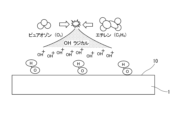
- FIG. FIG. 3 is a schematic diagram for explaining a radical reaction in the hydroxyl group formation step S1.
- FIG. 2 is a schematic configuration diagram for explaining a chamber 2A applicable to the substrate bonding method according to Example 1 (a diagram showing the inside of the chamber 2A seen through).
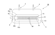
- FIG. 2 is a schematic configuration diagram (seeing through the inside of chamber 2B) for explaining a chamber 2B applicable to the substrate bonding method according to Example 1.
- FIG. FIG. 7 is a schematic configuration diagram (a diagram showing the interior of the chamber 2C) for explaining a chamber 2C applicable to the substrate bonding method according to Example 5;
- the bonding method of the substrates according to the embodiment of the present invention is a method of forming hydroxyl groups by performing a treatment using water as a raw material (aqueous solution treatment, steam plasma treatment, etc.) in the hydroxyl group forming step, as in a general direct bonding method. , simply referred to as the conventional method).
- the unsaturated hydrocarbon gas and the ozone gas having an ozone concentration of more than 50% by volume are supplied to the surfaces of the substrates to be bonded in the hydroxyl group forming step.
- OH radicals generated by a radical reaction between both a saturated hydrocarbon gas and the ozone gas are exposed to the surfaces to be joined, thereby forming hydroxyl groups (a molecular layer of hydroxyl groups) on the surfaces to be joined.
- each of the substrates to be joined is heated to cause the hydroxyl groups to undergo a dehydration condensation reaction.
- the joining substrates are joined at the surfaces to be joined.
- the surface roughness of the surface to be bonded is kept sufficiently small (for example, This makes it easier to carry out the lamination process and bonding process as desired. This makes it easier to join the respective substrates to be joined at the surfaces to be joined as desired.
- the method for joining substrates of this embodiment involves exposing the surfaces of the substrates to be joined to OH radicals generated by the radical reaction of both unsaturated hydrocarbon gas and ozone gas in the hydroxyl group forming step.
- Any material that can form hydroxyl groups on the surface to be joined may be used.
- common technical knowledge in various fields for example, direct bonding, chamber, ozone gas, unsaturated hydrocarbon gas, radical reaction, surface treatment, film formation by CVD, ALD, etc.
- Examples 1 to 5 described below are examples thereof. In Examples 1 to 5, which will be described later, detailed explanations will be omitted as appropriate, for example, by using the same reference numerals for overlapping contents.
- the resist removal technology using radical reactions as described above is highly effective in removing organic substances from photoresists, etc., and has been put into practical use, for example, for ashing photoresists and removing organic substances from surfaces without thermal damage or plasma damage. There is.
- a radical reaction the carbon double bond is initially cleaved by ozone molecules, and the unstable methylene peroxide generated along with this acts as an intermediate and causes a further fission reaction, producing OH radicals along with carbon dioxide gas and water. It generates formic acid, etc.
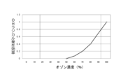
- An example of this radical reaction can be expressed by a characteristic diagram of ozone gas concentration and OH radical generation efficiency as shown in FIG.
- ozone gas generators e.g., general discharge type ozonizers
- the ozone gas that could be supplied was at a low concentration (e.g., the maximum ozone concentration was about 23% by volume), but in recent years, ozone gas has been safely supplied at high concentrations.
- devices that can generate ozone for example, Meidensha's pure ozone generator
- various surface treatment techniques that apply radical reactions have begun to be investigated.
- Patent Documents 3 and 4 the surface of a surface-treated object (modified object) is oxidized using OH radicals, and hydrophilic groups mainly including hydroxyl groups are formed (a molecular layer of hydrophilic groups).
- hydrophilic groups mainly including hydroxyl groups are formed (a molecular layer of hydrophilic groups).
- Patent Documents 3 and 4 by supplying unsaturated hydrocarbon gas and ozone gas into a chamber containing an object to be reformed, a radical reaction is caused near the surface of the object to be reformed.
- a method of modifying the surface of the object to be modified using OH radicals generated by a radical reaction is disclosed.
- unsaturated hydrocarbon gas and ozone gas are supplied into the chamber via a shower head that integrates an unsaturated hydrocarbon gas supply section and an ozone gas supply section (numeral 9 in Patent Document 3, reference numeral 10 or 15 in Patent Document 4). Also disclosed is a configuration for supplying.
- the energy (chemical reaction energy) due to the radical reaction may act on the surface of the substrate to be joined, for example, plasma treatment as in the conventional method It is possible to avoid the effects of energy caused by such things (energy that can cause plasma damage). Therefore, the surface roughness of the surface to be joined can be kept sufficiently small.
- the surface roughness of each substrate to be bonded is kept sufficiently small at the atomic level ( It is desirable to perform the lamination process and bonding process while maintaining good flatness.
- the hydroxyl group formation process applying the radical reaction as described above, after the hydroxyl group formation process, the surface to be joined of each substrate to be joined maintains a sufficiently small surface roughness at the atomic level (good flatness). It is possible to obtain a desired optical lens by carrying out the lamination process and bonding process as appropriate.
- Example 1 The bonding method of Example 1 is to sequentially perform the hydroxyl group forming step S1, the laminating step S2, and the bonding step S3 as shown in FIG.
- the substrates to be bonded 1a and 1b (hereinafter appropriately referred to simply as the substrate to be bonded 1) are bonded at the bonded surface 10, and in the hydroxyl group forming step S1, a radical reaction as shown in the above-mentioned reference example is carried out. This is what was used.
- unsaturated hydrocarbon gas and ozone gas having an ozone concentration of more than 50% by volume are supplied to the surface 10 of the substrate 1 to be bonded.
- a radical reaction occurs near the surface 10 of the substrate 1 to be bonded due to both the unsaturated hydrocarbon gas (ethylene in FIG. 3) and the ozone gas (pure ozone in FIG. 3), as shown in FIG. 3, for example.
- OH radicals (OH + ) generated by the radical reaction are exposed to the surface 10 of the substrate 1 to be bonded, and a hydroxyl group (a molecular layer of hydroxyl groups indicated by the symbol OH in the figure) is formed on the surface 10 to be bonded. will be formed.
- the two substrates to be joined 1a and 1b on which hydroxyl groups have been formed in the hydroxyl group forming step S1 are laminated (temporarily joined) by overlapping each other on the surfaces to be joined 10. It is preferable that the laminated substrates 1a and 1b are pressed against each other at the surfaces 10 to be joined (for example, pressed under pressure of 1 MPa or more) to be brought into sufficient contact with each other.
- the hydroxyl groups are subjected to a dehydration condensation reaction by heating each of the substrates 1a and 1b to be bonded that have been laminated in the lamination step S2.
- the respective substrates 1a and 1b to be joined are joined at the surfaces 10 to be joined.
- the substrate 1 to be bonded is housed in a chamber, the pressure inside the chamber is reduced, and unsaturated hydrocarbon gas and ozone gas are respectively supplied into the chamber.
- This chamber may be of any type as long as it can supply unsaturated hydrocarbon gas and ozone gas while accommodating the substrate 1 to be bonded as described above, and can form hydroxyl groups on the surface 10 to be bonded, and various embodiments are applicable. It is.
- chamber 2 As an example, in the chamber 2 shown in FIG. 4 (chamber 2A in FIG. 4, chambers 2B and 2C in FIGS. 5 and 6 described below; hereinafter referred to simply as chamber 2), there is unsaturated carbonization in the chamber 2.
- An unsaturated hydrocarbon gas supply section 3 that supplies hydrogen gas
- an ozone gas supply section 4 that supplies ozone gas into the chamber 2
- a gas discharge section that takes in the gas in the chamber 2 and discharges it to the outside of the chamber 2.
- the gas exhaust section 5 not only simply takes in the gas inside the chamber 2 and discharges it outside the chamber 2, but also maintains the inside of the chamber 2 in a reduced pressure state (for example, a state in which the inside of the chamber 2 is in a vacuum environment). Examples include embodiments in which it is possible to maintain
- a similar configuration of the chamber 2 as described above is disclosed in Patent Documents 1 to 6, and it is also possible to apply the configuration as appropriate.
- a control unit that can adjust the supply flow rate, supply flow rate ratio, supply time, etc. of unsaturated hydrocarbon gas and ozone gas by the unsaturated hydrocarbon gas supply unit 3 and ozone gas supply unit 4, and the unsaturated hydrocarbon gas and ozone gas
- a gas supply section (a raw material gas supply section 7 and an inert gas supply section 8 in FIG. 6, which will be described later) that supply gases other than the above.
- the unsaturated hydrocarbon gas supply section 3 and the ozone gas supply section 4 (for example, in FIG. 6 described later, a raw material gas supply section 7 and an inert gas supply section 8) are integrated to constitute a shower head, and the shower head is It is also possible to supply unsaturated hydrocarbon gas or ozone gas into the chamber 2 through the gas.
- the substrates to be bonded 1 may be appropriately supported.
- the support structure and the like are not particularly limited.
- the chamber 2A shown in FIG. 4 may be configured to support a plurality of substrates 1 to be bonded, thereby making it possible to simultaneously perform the hydroxyl group forming step S1 on each substrate 1 to be bonded.
- a plurality of substrates 1 to be bonded housed in the chamber 2B may be movably supported, or each substrate 1 to be bonded may be pressurized or heated. It's okay.
- the chamber 2B includes a support portion 6 capable of supporting the two substrates to be joined 1a and 1b, respectively.
- the support section 6 includes a pair of support stands 61a, 61b that support the two substrates 1a, 1b, respectively, and are arranged opposite to each other, and the support stands 61a, 61b are arranged in the opposing directions (hereinafter simply referred to as opposite directions).
- a pair of support arms 62a, 62b that support the outer peripheral edge sides of the support stands 61a, 61b so as to be able to move toward and away from each other with respect to
- the rotating shaft 63 is rotatably supported.
- the support section 6 configured in this manner allows the support arms 62a and 62b to be rotated about the rotating shaft 63 by, for example, an operation section outside the chamber 2B (not shown), and the support stands 61a and 61b can be rotated in opposite directions. It is designed to be able to move towards and away from each other. Furthermore, the support stands 61a and 61b are provided with heating units (not shown) capable of heating the substrates to be joined 1a and 1b supported by the support stands 61a and 61b, respectively. .
- steps S1 to S3 can be performed appropriately on the substrates 1a and 1b to be joined.
- steps S1 to S3 can be performed appropriately on the substrates 1a and 1b to be joined.
- step S1 As shown in FIG. , supported on support stands 61a and 61b.
- unsaturated hydrocarbon gas and ozone gas are supplied from the unsaturated hydrocarbon gas supply section 3 and the ozone gas supply section 4, respectively.
- a radical reaction as shown in FIG. 3 occurs near the surfaces 10 of each of the substrates 1a and 1b to be joined, and hydroxyl groups are formed on the surfaces 10 to be joined.
- the lamination step S2 by operating the support part 6 and bringing the support stands 61a and 61b closer in opposite directions, the surfaces 10 of the substrates 1a and 1b to be joined are overlapped and stacked together. Can be pressure-welded.
- the bonding step S3 the laminated (press-bonded) substrates 1a and 1b to be bonded are heated by the heating section to cause a dehydration condensation reaction of hydroxyl groups, and each of the substrates 1a and 1b to be bonded is heated. They will be joined at the joining surface 10.
- the steps S1 to S3 of the substrates 1a and 1b to be joined can be performed in-situ in the same chamber 2B.
- the substrate 1 to be bonded may be taken out from the chamber 2A and the lamination step S2 and the bonding step S3 may be performed. It is conceivable that some moisture may remain.
- steps S1 to S3 can be performed in-situ as described above, so that it becomes easier to prevent moisture from remaining on the surface to be joined 10.
- the unsaturated hydrocarbon gas and the ozone gas may each cause a radical reaction in the hydroxyl group forming step S1 and may form hydroxyl groups on the surface to be joined 10, and various embodiments are applicable.
- Specific examples of the unsaturated hydrocarbon gas include those shown in Table 1 below.
- ozone gas examples include those having an ozone concentration of more than 50% by volume, more preferably a high concentration (for example, 90% by volume or more).
- the substrate 1 to be joined can be appropriately applied as long as it can form hydroxyl groups on the surface 10 to be joined in the hydroxyl group forming step S1, and can be directly joined through the subsequent lamination step S2 and bonding step S3.
- the surface 10 to be joined may be flattened in advance (for example, flattened by CMP or the like so that the surface roughness is sufficiently small at the atomic level). can be mentioned.
- the hydroxyl group forming step S1 and the bonding step S3 can be performed at relatively low temperatures, for example, when the substrate 1 to be bonded is a substrate or a film, it is possible to use a substrate with relatively high heat resistance such as a silicon substrate.
- the material is not limited, and may be a substrate made of a synthetic resin with relatively low heat resistance.
- Examples include various substrates used in MEMS, semiconductors, FPDs, etc., such as silicon substrates, glass substrates, GaN substrates, SiC substrates, and diamond substrates, metal substrates, film-like substrates, and silicon oxide films ( Examples include substrates provided with a SiO 2 film), and examples include selecting and applying the same type or different types of substrates from these substrates.
- the resin examples include those using polyester resin, aramid resin, olefin resin, polypropylene, PPS (polyphenylene sulfide), PET (polyethylene terephthalate), and the like.
- PE polyethylene
- PEN polyethylene naphthalate
- POM polyoxymethylene or acetal resin
- PEEK polyetheretherketone
- ABS resin acrylonitrile, butadiene, styrene copolymer synthetic resin
- PA examples include those using polyamide), PFA (tetrafluoroethylene, perfluoroalkoxyethylene copolymer), PI (polyimide), PVD (polyvinyl dichloride), acrylic resin, and the like.
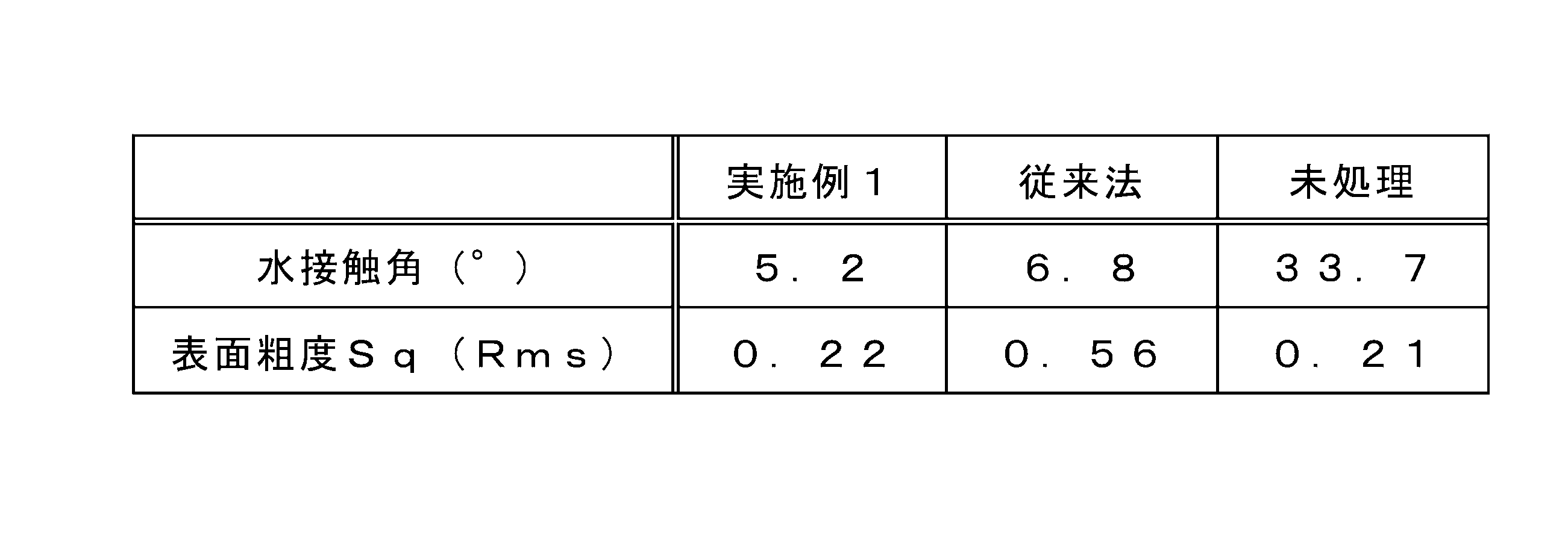
- Example 1 ⁇ Verification> Next, the bonding method according to Example 1 was verified under the verification conditions shown below. First, a case where a substrate 1 to be bonded made of flat alkali-free glass was applied and the hydroxyl group forming step S1 of Example 1 was performed, and a case where a conventional hydroxyl group forming step (O 2 plasma treatment) was performed. When the water contact angle (°) and surface roughness Sq (Rms) of the surface to be joined 10 were observed, the results shown in Table 2 below were obtained. In addition, in the hydroxyl group forming step S1 of Example 1, ethylene was applied as the unsaturated hydrocarbon gas.
- Example 1 in the hydroxyl group forming step S1, sufficient moisture is applied to the surface to be bonded 10 of the substrate 1 to be bonded while suppressing moisture from remaining on the surface to be bonded. A large amount of hydroxyl groups can be formed, and a dehydration condensation reaction of the hydroxyl groups is likely to occur in the bonding step S3.
- the surface roughness of the surfaces 10 to be joined can be maintained in a sufficiently small state, and the subsequent lamination process S2 and bonding process S3 can be performed as desired. It becomes easier to do. This shows that it is possible to join each of the substrates 1 to be joined at the surfaces 10 to be joined as desired.
- unsaturated carbonization which is the supply flow rate ratio of both unsaturated hydrocarbon gas (e.g., ethylene) and ozone gas (e.g., ozone gas with an ozone gas concentration of 90% by volume or more), is The optimal ratio of hydrogen gas to ozone gas is considered to be about 1:3.
- unsaturated hydrocarbon gas e.g., ethylene
- ozone gas e.g., ozone gas with an ozone gas concentration of 90% by volume or more
- the optimum value of the supply flow rate ratio of about 1:3 (hereinafter simply referred to as the general optimum value) is the molar ratio (1:2) when ethylene molecules and ozone molecules undergo a complete oxidation reaction, and the It is a ratio that can be determined empirically by noting that the flow rate ratio and the molar ratio are equivalent and conducting appropriate oxidation reaction experiments.
- Example 2 it was considered to appropriately set the supply flow rate ratio and the water contact angle of the surface to be joined 10 suitable for the hydroxyl group forming step S1.
- the radical reaction in the hydroxyl group forming step S1 is a reaction in which OH radicals are generated during the multistage reaction of unsaturated hydrocarbon gas with ozone gas, as described above. Therefore, in a multistage reaction, when the ratio of ozone gas is set to be larger than the general optimum value, although the radical reaction itself can be maintained, the generation of OH radicals can be suppressed in accordance with the increased proportion. As a result, it is conceivable that the amount of hydroxyl groups formed on the surface to be joined 10 can also be suppressed.
- the supply time of both the unsaturated hydrocarbon gas and the ozone gas in the hydroxyl group forming step S1 was set to 1 minute.
- the symbol “ ⁇ ” indicates that the substrates 1a and 1b to be bonded were bonded as desired, and the symbol “ ⁇ ” indicates that the substrates 1a and 1b were bonded to a certain extent, although not as desired. If the bonding was successful, an "x" indicates that the substrates 1a and 1b to be bonded could not be bonded.
- the second embodiment in addition to producing the same effects as in the first embodiment, the following can be said. That is, there is a correlation between the amount of hydroxyl groups formed on the surface 10 to be bonded and the water contact angle of the surface 10, and as the amount of hydroxyl groups increases, the water contact angle decreases. It turns out that it will happen.
- the supply flow rate ratio unsaturated hydrocarbon gas/ozone gas
- the water contact angle of the surface to be joined 10 is controlled, that is, the amount of hydroxyl groups formed on the surface to be joined 10 is controlled. I see that it is possible.
- the amount of hydroxyl groups formed on the surface 10 to be joined can be prevented from becoming too large than necessary, and the generation of moisture can be suppressed, it becomes easier to join the substrates 1a and 1b to be joined as desired. I understand.
- Example 3 In Example 3, in the hydroxyl group forming step S1, the supply flow rate ratio (unsaturated hydrocarbon gas/ozone gas) of both unsaturated hydrocarbon gas and ozone gas into the chamber 2 is kept constant, and the supply flow rate and supply time of both are kept constant. We considered adjusting the amount as appropriate.
- the third embodiment in addition to providing the same effects as those of the first and second embodiments, the following can be said. That is, even if the supply flow rate ratio in the hydroxyl group forming step S1 is constant, the amount of hydroxyl groups formed on the surface to be joined 10 can be adjusted by appropriately adjusting the supply flow rates and supply times of the unsaturated hydrocarbon gas and ozone gas. It can be seen that since it is possible to prevent the amount from increasing too much and to suppress the generation of moisture, it becomes easier to bond the substrates 1a and 1b to be bonded as desired.
- Example 4 hybrid bonding of the substrate 1 to be bonded, in which the metal wiring (electrode) is provided on the surface 10 to be bonded, was performed through steps S1 to S3 was considered.
- metal wiring area the area where wiring is provided (hereinafter simply referred to as metal wiring area) is bonded (Cu--Cu direct bonding) by the following mechanism.
- the hydroxyl groups in each metal wiring region are first removed by diffusion, and then the metal wiring regions are interdiffused (interdiffusion of Cu molecules). As a result, they are joined to each other. Therefore, from the viewpoint of bonding the metal wiring regions of each substrate 1 to be bonded, it can be seen that hydroxyl groups can be a factor that inhibits the bonding (hereinafter referred to simply as a metal bonding inhibiting factor).
- a metal bonding inhibiting factor if an oxide film (Cu oxide film) is formed in the metal wiring area of each substrate 1 to be joined, or if moisture remains in the metal wiring area, the oxide film and moisture will also be removed from the metal bonding area. This can be a hindrance.
- the amount of hydroxyl groups formed on the surfaces 10 can be reduced by performing hybrid bonding through steps S1 to S3. It can be seen that the substrates 1a and 1b to be bonded can be sufficiently bonded as desired because it is possible to prevent the amount from increasing more than necessary and also to suppress the generation of moisture.
- Example 5 When a silicon substrate provided with a silicon oxide film (SiO 2 film) is used as the substrate 1 to be bonded, moisture remaining on the surface of the silicon oxide film (surface 10 to be bonded) and dehydration condensation in the bonding step S3 This is expected in the field of direct bonding because the moisture generated by the reaction can be easily diffused into the silicon oxide film in the dehydration condensation reaction, that is, easily removed from the surface 10 to be bonded.
- SiO 2 film silicon oxide film
- a silicon oxide film is formed on the side of the surface 10 to be bonded by an oxide film forming process such as a CVD method before performing steps S1 to S3. (forming with a film thickness greater than the unevenness) or, if necessary, by flattening the surface of the silicon oxide film by CMP (chemical mechanical polishing), etc., a flat surface 10 to be bonded is formed on the silicon oxide film.
- an oxide film forming process such as a CVD method before performing steps S1 to S3. (forming with a film thickness greater than the unevenness) or, if necessary, by flattening the surface of the silicon oxide film by CMP (chemical mechanical polishing), etc.
- a silicon oxide film formed by a general CVD method or the like is formed at a relatively high temperature (for example, over 200°C), so there is a difference in the coefficient of thermal expansion between the substrate 1 to be bonded and the silicon oxide film. exists, thermal distortion (warpage) of both is likely to occur. That is, if a silicon oxide film is formed on the substrate 1 to be bonded in a high-temperature atmosphere as described above and then the substrate 1 to be bonded is moved to a room temperature atmosphere, thermal distortion will occur due to temperature changes.
- the CVD method and ALD method shown in Patent Documents 5 and 6 utilize a radical reaction at a relatively lower temperature (for example, about room temperature to 100° C.) than the general CVD method etc. to Taking note of the fact that a gas supply system capable of forming an oxide film and applicable to the hydroxyl group forming step S1 was used, a chamber 2C as shown in FIG. 6 was constructed.
- the chamber 2C shown in FIG. 6 has the same configuration as the chambers 2A and 2B, except that the chamber 2C has a raw material gas supply section 7 so as to be able to supply the raw material gas for forming a silicon oxide film in the chamber 2C. It is important to have the following.
- the chamber 2C is supported by an inert gas supply section 8 that supplies inert gas into the chamber 2C as shown in FIG. 6, a support section 6 as shown in FIG.
- a heating section capable of heating the substrate 1 to be joined may be provided.
- the raw material gas may be any gas containing Si, which is an element that forms a silicon oxide film, as a constituent element, and various embodiments can be applied.
- organic gas sources appropriately selected from the group of organic gas sources including TEOS (TetraEthyl OrthoSillicate), HMDS-O (hexamethyldisiloxane), HMDS-N (hexamethyldisilazane), etc. may be applied. It will be done.
- any inert gas may be used as long as it is applicable to, for example, purging the inside of the chamber 2, and examples thereof include inert gases such as N 2 , Ar, and He.
- an oxide film is formed in the chamber 2C by the oxide film forming process of the CVD method or ALD method that utilizes the radical reaction of both unsaturated hydrocarbon gas and ozone gas.
- a silicon oxide film (not shown) can be provided on the one end side surface.
- unsaturated hydrocarbon gas and ozone gas are appropriately supplied to the surface of the silicon oxide film of the substrate 1 to be bonded (surface 10 to be bonded) of the substrate 1 to be bonded housed in the chamber 2C in the hydroxyl group forming step S1. Hydroxyl groups can be formed on the surface.
- an oxide film forming step is performed on one end side surface (the surface to be joined 10 side) of each of the two substrates 1a and 1b. Not only can the hydroxyl group forming step S1 be performed, but also the laminating step S2 and the bonding step S3 can be performed.
- the oxide film forming step and steps S1 to S3 of the substrates 1a and 1b to be bonded can be performed in-situ in the same chamber 2C, and the steps S1 to S3 of the substrates 1a and 1b to be bonded can be performed in-situ. It becomes possible to suppress thermal distortion.
- silicon substrates are housed as substrates 1a and 1b to be bonded in a chamber 2C equipped with a support section 6 and a heating section, and CVD is performed using a radical reaction of both unsaturated hydrocarbon gas and ozone gas as described above.
- a silicon oxide film was formed on the bonding surface 10 side of the substrates 1a and 1b to be bonded by performing an oxide film forming step using a method or an ALD method.
- the following can be said. That is, it can be seen that since the step of forming an oxide film on the substrate 1 to be bonded 1 and steps S1 to S3 can be performed in-situ, the substrates 1a and 1b to be bonded can be bonded as desired and efficiently.
- the metal wiring provided on the substrates 1a and 1b to be bonded is not limited to those made of copper or gold, but may also be made of metals appropriately selected from the group of various metals such as tungsten and aluminum. There are also things that consist of.
Landscapes
- Chemical & Material Sciences (AREA)
- Organic Chemistry (AREA)
- Pressure Welding/Diffusion-Bonding (AREA)
- Lining Or Joining Of Plastics Or The Like (AREA)
- Laminated Bodies (AREA)
Abstract
Description
例えば特許文献1,2では、不飽和炭化水素ガスとオゾンガスとのラジカル反応により発生するOHラジカル等の活性種(酸化種)を利用して、表面処理対象物の表面に付着しているレジストを除去する技術が開示されている。このレジスト除去技術は、オゾンの特性を利用したものであって、例えば熱エネルギー(加熱)やUV照射を施さなくても、当該オゾンが不飽和炭化水素の炭素の2重結合と反応し易いことを利用したものである。
本実施例1の接合方法は、図2に示したような水酸基形成工程S1,積層工程S2,接合工程S3を順に行うことにより、複数個の被接合基体1(図2では2個の平板状の被接合基体1a,1b;以下、適宜纏めて単に被接合基体1と称する)を被接合面10にて接合するものであって、当該水酸基形成工程S1において前記参考例に示すようなラジカル反応を利用したものである。
水酸基形成工程S1では、例えばチャンバ内に被接合基体1を収容して当該チャンバ内を減圧状態にし、当該チャンバ内に不飽和炭化水素ガスおよびオゾンガスをそれぞれ供給することにより、当該被接合基体1の被接合面10に水酸基を形成することが挙げられる。このチャンバは、前記のように被接合基体1を収容した状態で不飽和炭化水素ガスおよびオゾンガスを供給でき、当該被接合面10に水酸基を形成できるものであれば良く、種々の態様が適用可能である。
図2に示した水酸基形成工程S1,積層工程S2,接合工程S3(以下、適宜纏めて単に工程S1~S3と称する)においては、被接合基体1を適宜支持して行うことが挙げられるが、当該支持構成等は特に限定されるものではない。例えば、図4に示したチャンバ2Aにおいて、複数個の被接合基体1を支持する支持構成としても良く、これにより当該各被接合基体1において同時に水酸基形成工程S1を行うことが可能となる。
不飽和炭化水素ガス,オゾンガスは、それぞれ水酸基形成工程S1においてラジカル反応を起こし、被接合面10に対して水酸基を形成し得るものであれば良く、種々の態様が適用可能である。不飽和炭化水素ガスの具体例としては、下記表1に示すものが挙げられる。

被接合基体1は、水酸基形成工程S1によって被接合面10に水酸基を形成できるものであって、その後の積層工程S2,接合工程S3を経て直接接合できるものであれば適宜適用可能で有り、特に限定されるものではないが、必要に応じて、予め当該被接合面10を平坦化処理(例えば、CMP等により、原子レベルで十分小さい表面粗度となるように平坦化処理)しておくことが挙げられる。
次に、以下に示す検証条件により、実施例1による接合方法の検証を行った。まず、平板状の無アルカリガラスから成る被接合基体1を適用し、実施例1の水酸基形成工程S1を行った場合と、従来法の水酸基形成工程(O2プラズマ処理)を行った場合と、における被接合面10の水接触角(°),表面粗度Sq(Rms)を観察したところ、下記表2に示すような結果が得られた。なお、実施例1の水酸基形成工程S1では、エチレンを不飽和炭化水素ガスとして適用した。
例えば、特許文献1,2に示すような表面処理技術においては、不飽和炭化水素ガス(例えばエチレン)およびオゾンガス(例えばオゾンガス濃度90体積%以上のオゾンガス)の両者の供給流量比である不飽和炭化水素ガス:オゾンガスの最適値は、約1:3となることが考えられる。この約1:3という供給流量比の最適値(以下、単に一般的最適値と称する)は、エチレン分子とオゾン分子が完全に酸化反応する場合のモル比(1:2)であり、前記供給流量比と前記モル比とが等価であることに着目し、酸化反応実験等を適宜行うことにより経験的に条件出しできる比率である。
次に、以下に示す検証条件により、本実施例2による接合方法の検証を行った。まず、シリコン酸化膜(SiO2膜)が設けられているシリコン基板を被接合基体1a,1bとして適用し、不飽和炭化水素ガスとしてエチレンガスを適用した。そして、水酸基形成工程S1において供給流量比の不飽和炭化水素ガス:オゾンガスを適宜設定して行った後、被接合面10(シリコン酸化膜表面)の水接触角(°)を観察したところ、下記表3に示す結果が得られた。更に、当該水酸基形成工程S1を行った後の被接合基体1a,1bにおいて、積層工程S2,接合工程S3を経て接合した場合の接合状況も観察したところ、下記表3に示すような結果が得られた。
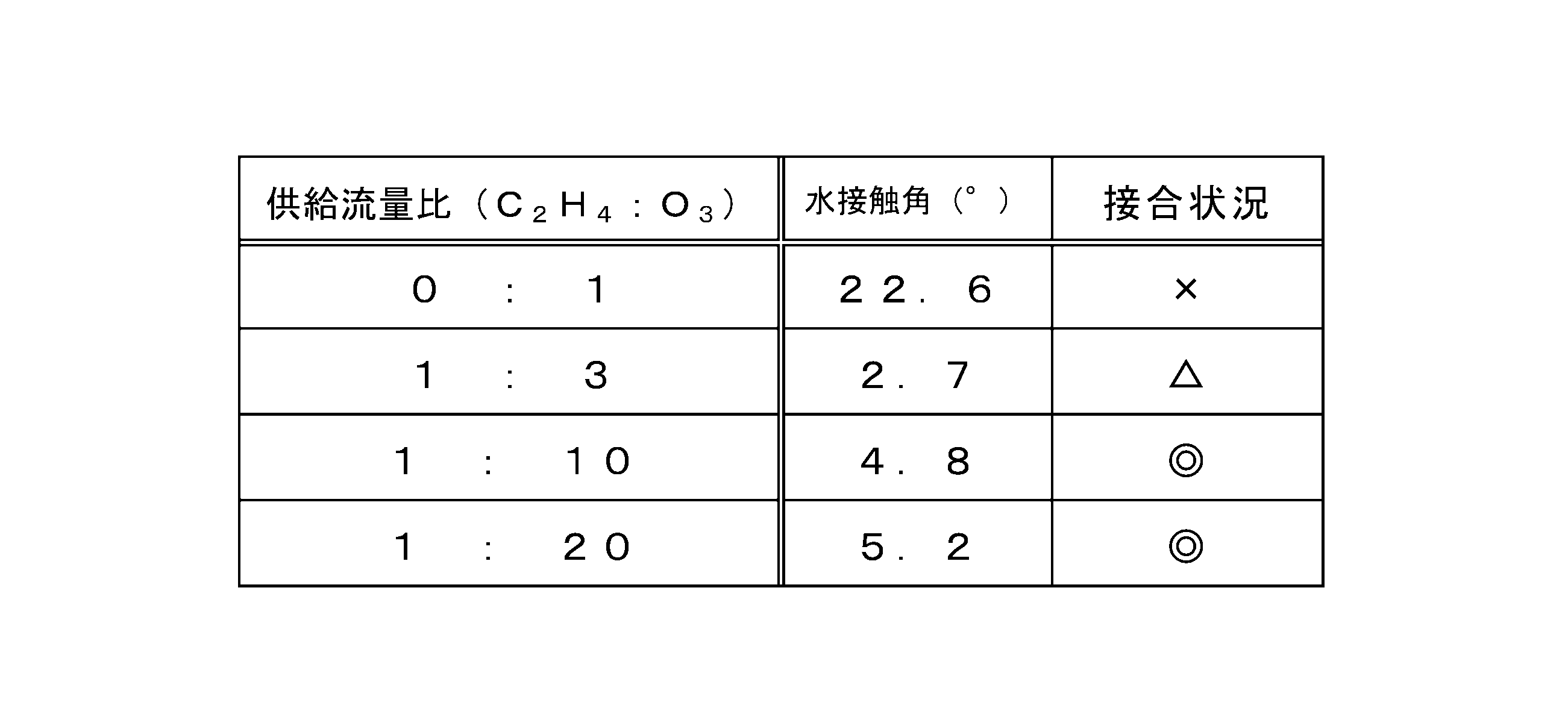
本実施例3では、水酸基形成工程S1において、チャンバ2内に対する不飽和炭化水素ガスおよびオゾンガスの両者の供給流量比(不飽和炭化水素ガス/オゾンガス)を一定にし、当該両者の供給流量,供給時間を適宜調整することを検討した。
実施例2と同様の検証条件であって、水酸基形成工程S1においては、供給流量比の不飽和炭化水素ガス:オゾンガスを一般的最適値よりもオゾンガスの比率が大きい値で一定とし、不飽和炭化水素ガスおよびオゾンガスの供給流量,供給時間を適宜設定して行った後、被接合面10(シリコン酸化膜表面)の水接触角(°)を観察したところ、実施例2と同様の結果が得られた。更に、当該水酸基形成工程S1を行った後の被接合基体1a,1bにおいて、積層工程S2,接合工程S3を経て接合した場合の接合状況も観察したところ、実施例2と同様の結果が得られた。
本実施例4では、被接合面10に金属配線(電極)が設けられている被接合基体1について、工程S1~S3を経てハイブリッド接合することを検討した。
そこで、前記のように銅または金を用いて成る金属配線が設けられている被接合基体1a,1bにおいて、実施例2,3の検証条件と同様の工程S1~S3を経て接合した場合の接合状況を観察したところ、当該実施例2,3と同様の結果が得られた。この結果により、水酸基形成工程S1のラジカル反応においては、被接合面10に形成する水酸基の量が必要以上に多くなり過ぎず、水分の発生が抑制されていることが判る。
シリコン酸化膜(SiO2膜)が設けられているシリコン基板は、被接合基体1として適用した場合、当該シリコン酸化膜の表面(被接合面10)に残存する水分や、接合工程S3の脱水縮合反応により発生する水分を、当該脱水縮合反応においてシリコン酸化膜中に拡散、すなわち被接合面10から除去し易くなる可能性があるため、直接接合分野では期待されている。
まず、支持部6や加温部を備えたチャンバ2C内に、シリコン基板を被接合基体1a,1bとして収容し、前記のように不飽和炭化水素ガスおよびオゾンガスの両者のラジカル反応を利用したCVD法またはALD法の酸化膜形成工程を行うことにより、当該被接合基体1a,1bの被接合面10側にシリコン酸化膜を形成した。そして、当該シリコン酸化膜を形成した被接合基体1a,1bにおいて、実施例2,3の検証条件と同様の工程S1~S3を経て接合した場合の接合状況を観察したところ、当該実施例2,3と同様の結果が得られ、当該被接合基体1a,1bの熱歪による影響は観られなかった。
Claims (14)
- チャンバ内に収容した被接合基体の被接合面に水酸基を形成する水酸基形成工程と、
前記水酸基を形成した2個の前記被接合基体を被接合面にて重ね合わせて積層する積層工程と、
前記積層した状態の各被接合基体を加熱することにより、当該各被接合基体を被接合面にて接合する接合工程と、
を有し、
前記水酸基形成工程は、前記チャンバ内に収容した被接合基体の被接合面に対し、不飽和炭化水素ガスおよびオゾン濃度50体積%超のオゾンガスをそれぞれ供給することにより、当該不飽和炭化水素ガスおよび当該オゾンガスの両者のラジカル反応により発生するOHラジカルを当該被接合面に曝露して、当該被接合面に対して水酸基を形成し、
前記接合工程は、前記加熱によって前記水酸基を脱水縮合反応させることを特徴とする基体の接合方法。 - 前記チャンバには、
前記チャンバ内に前記不飽和炭化水素ガスを供給する不飽和炭化水素ガス供給部と、
前記チャンバ内に前記オゾンガスを供給するオゾンガス供給部と、
前記チャンバ内のガスを吸気して当該チャンバ外に排出するガス排出部と、
が備えられており、
前記水酸基形成工程は、前記チャンバ内を減圧状態にして行うことを特徴とする請求項1記載の基体の接合方法。 - 前記水酸基形成工程により、前記被接合基体の被接合面の水接触角を4°~10°の範囲内にすることを特徴とする請求項1または2記載の基体の接合方法。
- 前記水酸基形成工程は、前記チャンバ内に対する前記不飽和炭化水素ガスおよび前記オゾンガスの両者の供給流量比を調整することにより、前記被接合基体の被接合面に対する水酸基の量を制御することを特徴とする請求項3記載の基体の接合方法。
- 前記水酸基形成工程は、前記チャンバ内に対する前記不飽和炭化水素ガスおよび前記オゾンガスの両者の供給流量比が一定となるように、当該両者の供給流量および供給時間を調整することにより、前記被接合基体の被接合面に対する水酸基の量を制御することを特徴とする請求項3記載の基体の接合方法。
- 前記各被接合基体の被接合面には、銅,金,タングステン,アルミニウムのうち何れかを用いてなる金属配線がそれぞれ設けられており、
前記接合工程により、前記各被接合基体それぞれに設けられた金属配線を互いに接合することを特徴とする請求項1または2記載の基体の接合方法。 - 前記チャンバは、当該チャンバ内に前記各被接合基体をそれぞれ支持する支持部を、備え、
前記支持部は、前記各被接合基体を、それぞれの被接合面が互いに対向した姿勢で、当該対向する方向に対して接離自在に移動できるように支持することを特徴とする請求項1または2記載の基体の接合方法。 - 前記各被接合基体の被接合面は、前記水酸基形成工程よりも前工程である酸化膜形成工程によって予め当該各被接合基体それぞれの一端側面に設けられたシリコン酸化膜の表面であることを特徴とする請求項1または2記載の基体の接合方法。
- 前記水酸基形成工程により、前記被接合基体の被接合面の水接触角を4°~10°の範囲内にすることを特徴とする請求項8記載の基体の接合方法。
- 前記チャンバは、前記シリコン酸化膜を形成する元素であるSiを構成元素として含んでいる原料ガスを前記チャンバ内に供給する原料ガス供給部を、更に備えており、
前記酸化膜形成工程は、
前記不飽和炭化水素ガスおよび前記オゾンガスの両者のラジカル反応を利用した化学気相成長法または原子層堆積法により、前記チャンバ内に収容した前記被接合基体の一端側面に対し、前記不飽和炭化水素ガスと、前記オゾンガスと、前記原料ガスと、を供給して前記シリコン酸化膜を設けたことを特徴とする請求項8記載の基体の接合方法。 - 前記チャンバは、当該チャンバ内に前記各被接合基体をそれぞれ支持する支持部を、備え、
前記支持部は、前記各被接合基体を、それぞれの被接合面が互いに対向した姿勢で、当該対向する方向に対して接離自在に移動できるように支持することを特徴とする請求項10記載の基体の接合方法。 - 前記不飽和炭化水素ガスは、プロピレン、アセチレン、ブタジエン、ベンゼン、トルエン、O-キシレン、スチレン、α-ブチレン、1,3-ブタジエン、1,2-ブタジエン、3-メチル-1,2-ブタジエン、2-メチル-1,3-ブタジエン、1,3-ペンタジエン、2,3-ジメチル-1,3-ブタジエンのうち何れかから成ることを特徴とする請求項1または2記載の基体の接合方法。
- 前記各被接合基体それぞれは、シリコン基板,ガラス基板,GaN基板,SiC基板,ダイヤモンド基板,前記被接合基体の一端側面にシリコン酸化膜が設けられている基板,金属基板,フィルム状基板の群から選択された同種または異種の基板であることを特徴とする請求項1または2記載の基体の接合方法。
- 前記原料ガスは、TEOS,HMDS-O,HMDS-Nを含む有機ガスソースの群から選択された一種以上から成ることを特徴とする請求項10または11記載の基体の接合方法。
Priority Applications (1)
| Application Number | Priority Date | Filing Date | Title |
|---|---|---|---|
| EP23835314.8A EP4550385A4 (en) | 2022-07-06 | 2023-06-22 | SUBSTRATE ASSEMBLY PROCESS |
Applications Claiming Priority (2)
| Application Number | Priority Date | Filing Date | Title |
|---|---|---|---|
| JP2022-108755 | 2022-07-06 | ||
| JP2022108755A JP7431895B2 (ja) | 2022-07-06 | 2022-07-06 | 基体の接合方法 |
Publications (1)
| Publication Number | Publication Date |
|---|---|
| WO2024009780A1 true WO2024009780A1 (ja) | 2024-01-11 |
Family
ID=89453301
Family Applications (1)
| Application Number | Title | Priority Date | Filing Date |
|---|---|---|---|
| PCT/JP2023/023050 Ceased WO2024009780A1 (ja) | 2022-07-06 | 2023-06-22 | 基体の接合方法 |
Country Status (3)
| Country | Link |
|---|---|
| EP (1) | EP4550385A4 (ja) |
| JP (1) | JP7431895B2 (ja) |
| WO (1) | WO2024009780A1 (ja) |
Cited By (1)
| Publication number | Priority date | Publication date | Assignee | Title |
|---|---|---|---|---|
| CN119811987A (zh) * | 2025-03-12 | 2025-04-11 | 北京芯力技术创新中心有限公司 | 键合半导体器件的方法、叠层半导体器件和电子设备 |
Families Citing this family (2)
| Publication number | Priority date | Publication date | Assignee | Title |
|---|---|---|---|---|
| JP7628634B1 (ja) * | 2024-01-31 | 2025-02-10 | 明電ナノプロセス・イノベーション株式会社 | 表面処理装置,基体接合装置,表面処理方法,基体接合方法 |
| JP2025158213A (ja) * | 2024-04-04 | 2025-10-17 | 株式会社荏原製作所 | 基板接合方法および基板接合システム |
Citations (10)
| Publication number | Priority date | Publication date | Assignee | Title |
|---|---|---|---|---|
| JP4905253B2 (ja) | 2007-05-23 | 2012-03-28 | 株式会社明電舎 | レジスト除去方法及びその装置 |
| JP5217951B2 (ja) | 2007-12-04 | 2013-06-19 | 株式会社明電舎 | レジスト除去方法及びその装置 |
| JP6052470B1 (ja) | 2015-03-12 | 2016-12-27 | 株式会社明電舎 | 樹脂の改質方法 |
| JP6057030B1 (ja) | 2015-05-21 | 2017-01-11 | 株式会社明電舎 | 樹脂の改質方法 |
| JP2018125325A (ja) * | 2017-01-30 | 2018-08-09 | パナソニック・タワージャズセミコンダクター株式会社 | 半導体装置及びその製造方法 |
| JP6569831B1 (ja) | 2018-03-28 | 2019-09-04 | 株式会社明電舎 | 酸化膜形成方法 |
| WO2019187337A1 (ja) * | 2018-03-28 | 2019-10-03 | 株式会社明電舎 | 酸化膜形成方法 |
| WO2020170482A1 (ja) * | 2019-02-19 | 2020-08-27 | 株式会社明電舎 | 原子層堆積方法および原子層堆積装置 |
| WO2021053904A1 (ja) * | 2019-09-20 | 2021-03-25 | 株式会社明電舎 | 酸化膜形成装置 |
| JP7056710B2 (ja) | 2020-09-25 | 2022-04-19 | 株式会社明電舎 | 原子層堆積方法 |
-
2022
- 2022-07-06 JP JP2022108755A patent/JP7431895B2/ja active Active
-
2023
- 2023-06-22 EP EP23835314.8A patent/EP4550385A4/en active Pending
- 2023-06-22 WO PCT/JP2023/023050 patent/WO2024009780A1/ja not_active Ceased
Patent Citations (10)
| Publication number | Priority date | Publication date | Assignee | Title |
|---|---|---|---|---|
| JP4905253B2 (ja) | 2007-05-23 | 2012-03-28 | 株式会社明電舎 | レジスト除去方法及びその装置 |
| JP5217951B2 (ja) | 2007-12-04 | 2013-06-19 | 株式会社明電舎 | レジスト除去方法及びその装置 |
| JP6052470B1 (ja) | 2015-03-12 | 2016-12-27 | 株式会社明電舎 | 樹脂の改質方法 |
| JP6057030B1 (ja) | 2015-05-21 | 2017-01-11 | 株式会社明電舎 | 樹脂の改質方法 |
| JP2018125325A (ja) * | 2017-01-30 | 2018-08-09 | パナソニック・タワージャズセミコンダクター株式会社 | 半導体装置及びその製造方法 |
| JP6569831B1 (ja) | 2018-03-28 | 2019-09-04 | 株式会社明電舎 | 酸化膜形成方法 |
| WO2019187337A1 (ja) * | 2018-03-28 | 2019-10-03 | 株式会社明電舎 | 酸化膜形成方法 |
| WO2020170482A1 (ja) * | 2019-02-19 | 2020-08-27 | 株式会社明電舎 | 原子層堆積方法および原子層堆積装置 |
| WO2021053904A1 (ja) * | 2019-09-20 | 2021-03-25 | 株式会社明電舎 | 酸化膜形成装置 |
| JP7056710B2 (ja) | 2020-09-25 | 2022-04-19 | 株式会社明電舎 | 原子層堆積方法 |
Non-Patent Citations (1)
| Title |
|---|
| See also references of EP4550385A4 |
Cited By (1)
| Publication number | Priority date | Publication date | Assignee | Title |
|---|---|---|---|---|
| CN119811987A (zh) * | 2025-03-12 | 2025-04-11 | 北京芯力技术创新中心有限公司 | 键合半导体器件的方法、叠层半导体器件和电子设备 |
Also Published As
| Publication number | Publication date |
|---|---|
| EP4550385A1 (en) | 2025-05-07 |
| JP2024007593A (ja) | 2024-01-19 |
| JP7431895B2 (ja) | 2024-02-15 |
| EP4550385A4 (en) | 2025-09-17 |
Similar Documents
| Publication | Publication Date | Title |
|---|---|---|
| JP7431895B2 (ja) | 基体の接合方法 | |
| TW393671B (en) | Semiconductor device and its manufacturing method | |
| CN101421828B (zh) | 基板处理方法和基板处理装置 | |
| JP2009033179A5 (ja) | ||
| JP6030589B2 (ja) | ハードマスク形成方法及びハードマスク形成装置 | |
| JP2014093331A (ja) | 重合膜の成膜方法、成膜装置の環境維持方法、成膜装置、並びに電子製品の製造方法 | |
| TWI774662B (zh) | 基板之汽相氫氧自由基處理用系統及方法 | |
| US20100139708A1 (en) | Method of removing resist and apparatus therefor | |
| US12215210B2 (en) | Fluorine resin surface modification method, surface-modified fluorine resin production method, joining method, material having surface-modified fluorine resin, and joined body | |
| US10043975B2 (en) | Thin substrate, method for manufacturing same, and method for transporting substrate | |
| JP4924245B2 (ja) | 半導体製造装置、半導体装置の製造方法及び記憶媒体 | |
| CN111902564A (zh) | 氧化物膜形成方法 | |
| JP7628634B1 (ja) | 表面処理装置,基体接合装置,表面処理方法,基体接合方法 | |
| JP6008095B2 (ja) | チップの表面処理方法、接合方法、及び表面処理装置 | |
| US20150249008A1 (en) | Semiconductor process | |
| JP2023532517A (ja) | 低誘電率膜を堆積させるためのシステム及び方法 | |
| TWI832223B (zh) | 半導體裝置之製造方法及常溫接合裝置 | |
| JP2006258958A (ja) | 基板接着方法及び基板接着装置 | |
| US20150371855A1 (en) | Apparatus for etching two-dimensional material and method of patterning two-dimensional material using the same | |
| JP5024925B2 (ja) | 大気圧プラズマ処理方法 | |
| JP2011235557A (ja) | 接合膜転写装置および接合装置 | |
| JP2004343087A (ja) | 層間絶縁膜の表面改質方法及び表面改質装置 | |
| JP2011235558A (ja) | 接合膜転写装置および接合装置 | |
| TWI921883B (zh) | 用於形成具有降低的介電常數及高機械強度之低k介電材料的方法 | |
| TWI834388B (zh) | 層狀構造之製造方法、電子裝置之製造方法 |
Legal Events
| Date | Code | Title | Description |
|---|---|---|---|
| 121 | Ep: the epo has been informed by wipo that ep was designated in this application |
Ref document number: 23835314 Country of ref document: EP Kind code of ref document: A1 |
|
| WWE | Wipo information: entry into national phase |
Ref document number: 2023835314 Country of ref document: EP |
|
| NENP | Non-entry into the national phase |
Ref country code: DE |
|
| ENP | Entry into the national phase |
Ref document number: 2023835314 Country of ref document: EP Effective date: 20250131 |
|
| WWP | Wipo information: published in national office |
Ref document number: 2023835314 Country of ref document: EP |