WO2024013809A1 - 絶縁診断装置及び絶縁診断方法 - Google Patents
絶縁診断装置及び絶縁診断方法 Download PDFInfo
- Publication number
- WO2024013809A1 WO2024013809A1 PCT/JP2022/027278 JP2022027278W WO2024013809A1 WO 2024013809 A1 WO2024013809 A1 WO 2024013809A1 JP 2022027278 W JP2022027278 W JP 2022027278W WO 2024013809 A1 WO2024013809 A1 WO 2024013809A1
- Authority
- WO
- WIPO (PCT)
- Prior art keywords
- vector
- current
- phase
- zero
- negative
- Prior art date
- Legal status (The legal status is an assumption and is not a legal conclusion. Google has not performed a legal analysis and makes no representation as to the accuracy of the status listed.)
- Ceased
Links
Images


Classifications
-
- G—PHYSICS
- G01—MEASURING; TESTING
- G01R—MEASURING ELECTRIC VARIABLES; MEASURING MAGNETIC VARIABLES
- G01R31/00—Arrangements for testing electric properties; Arrangements for locating electric faults; Arrangements for electrical testing characterised by what is being tested not provided for elsewhere
- G01R31/34—Testing dynamo-electric machines
- G01R31/343—Testing dynamo-electric machines in operation
-
- G—PHYSICS
- G01—MEASURING; TESTING
- G01R—MEASURING ELECTRIC VARIABLES; MEASURING MAGNETIC VARIABLES
- G01R31/00—Arrangements for testing electric properties; Arrangements for locating electric faults; Arrangements for electrical testing characterised by what is being tested not provided for elsewhere
- G01R31/12—Testing dielectric strength or breakdown voltage ; Testing or monitoring effectiveness or level of insulation, e.g. of a cable or of an apparatus, for example using partial discharge measurements; Electrostatic testing
-
- G—PHYSICS
- G01—MEASURING; TESTING
- G01R—MEASURING ELECTRIC VARIABLES; MEASURING MAGNETIC VARIABLES
- G01R31/00—Arrangements for testing electric properties; Arrangements for locating electric faults; Arrangements for electrical testing characterised by what is being tested not provided for elsewhere
- G01R31/12—Testing dielectric strength or breakdown voltage ; Testing or monitoring effectiveness or level of insulation, e.g. of a cable or of an apparatus, for example using partial discharge measurements; Electrostatic testing
- G01R31/14—Circuits therefor, e.g. for generating test voltages, sensing circuits
-
- G—PHYSICS
- G01—MEASURING; TESTING
- G01R—MEASURING ELECTRIC VARIABLES; MEASURING MAGNETIC VARIABLES
- G01R31/00—Arrangements for testing electric properties; Arrangements for locating electric faults; Arrangements for electrical testing characterised by what is being tested not provided for elsewhere
- G01R31/34—Testing dynamo-electric machines
-
- G—PHYSICS
- G01—MEASURING; TESTING
- G01R—MEASURING ELECTRIC VARIABLES; MEASURING MAGNETIC VARIABLES
- G01R31/00—Arrangements for testing electric properties; Arrangements for locating electric faults; Arrangements for electrical testing characterised by what is being tested not provided for elsewhere
- G01R31/34—Testing dynamo-electric machines
- G01R31/346—Testing of armature or field windings
-
- G—PHYSICS
- G01—MEASURING; TESTING
- G01R—MEASURING ELECTRIC VARIABLES; MEASURING MAGNETIC VARIABLES
- G01R31/00—Arrangements for testing electric properties; Arrangements for locating electric faults; Arrangements for electrical testing characterised by what is being tested not provided for elsewhere
- G01R31/50—Testing of electric apparatus, lines, cables or components for short-circuits, continuity, leakage current or incorrect line connections
- G01R31/52—Testing for short-circuits, leakage current or ground faults
-
- H—ELECTRICITY
- H02—GENERATION; CONVERSION OR DISTRIBUTION OF ELECTRIC POWER
- H02P—CONTROL OR REGULATION OF ELECTRIC MOTORS, ELECTRIC GENERATORS OR DYNAMO-ELECTRIC CONVERTERS; CONTROLLING TRANSFORMERS, REACTORS OR CHOKE COILS
- H02P21/00—Arrangements or methods for the control of electric machines by vector control, e.g. by control of field orientation
- H02P21/14—Estimation or adaptation of machine parameters, e.g. flux, current or voltage
Definitions
- the present invention relates to an insulation diagnosis device and an insulation diagnosis method.
- insulation diagnostic methods such as withstand voltage tests and impulse gain tests for three-phase AC motors have been performed in a non-operating state (off-line state) in which the stator of the motor is removed from the power supply path. Further, the insulation diagnosis was an absolute value determination between the initial value and the value after the progress of deterioration.
- the insulation diagnosis method executed in the conventional insulation diagnosis apparatus uses absolute value determination, it is not possible to monitor the progress of deterioration leading to ground faults, layer shorts, etc., that is, the signs of deterioration. Furthermore, since conventional insulation diagnosis methods are performed with the motor in a non-operating state (off-line state), it is not possible to monitor deterioration signs or determine deterioration in real time while the motor is in operation.
- the present invention is capable of checking the progress of deterioration leading to ground faults, layer shorts, etc. in real time in the operating state of a three-phase AC motor, as well as immediately determining when a ground fault or layer short circuit occurs.
- An object of the present invention is to provide an insulation diagnosis device and an insulation diagnosis method that can perform the following steps.
- An insulation diagnostic device is an insulation diagnostic device that diagnoses the insulation of a three-phase AC motor based on the U-phase current, V-phase current, and W-phase current supplied to the three-phase AC motor.
- a current vector calculation unit that calculates at least one of a zero-phase current vector or a negative-phase current vector based on the phase current and the W-phase current, a reference current vector storage unit that stores a reference current vector in advance, and a current vector a current difference vector calculation unit that calculates a current difference vector that is the difference between the current vector calculated in the calculation unit and a reference current vector; and a determination unit that determines the insulation state of the three-phase AC motor based on the current difference vector. , is provided.
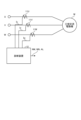
- FIG. 1 is an explanatory diagram of an insulation diagnostic device according to an embodiment.
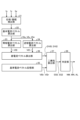
- FIG. 2 is a functional block diagram of the diagnostic device.
- FIG. 3 is an explanatory diagram of the primary zero-sequence current vector and the primary reference zero-sequence current vector.
- FIG. 4 is an explanatory diagram for calculating the primary zero-sequence current difference vector.
- FIG. 5 is an explanatory diagram of a tertiary zero-sequence current vector and a tertiary reference zero-sequence current vector.
- FIG. 6 is an explanatory diagram of the fifth-order zero-sequence current vector and the fifth-order reference zero-sequence current vector.
- FIG. 7 is an explanatory diagram of the seventh-order zero-sequence current vector and the seventh-order reference zero-sequence current vector.
- FIG. 8 is an operation processing flowchart of the embodiment.
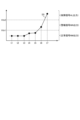
- FIG. 9 is an explanatory diagram of an example of the sum of squares, the first threshold value, and the second threshold value.
- FIG. 1 is an explanatory diagram of an insulation diagnostic device according to an embodiment.
- the insulation diagnostic device 10 includes a first current sensor (CT: Current Transformer) 11U that detects a U-phase current Iu supplied to a three-phase AC motor M, and a first current transformer (CT) 11U that detects a V-phase current Iv supplied to the three-phase AC motor M.
- CT Current Transformer
- CT second current transformer
- CT third current sensor
- a diagnostic device 12 that performs insulation diagnosis based on the W-phase current Iw is provided.
- FIG. 2 is a functional block diagram of the diagnostic device.
- the diagnostic device 12 includes a phase/amplitude detection section 21, a basic current vector calculation section 22, a zero-sequence current vector calculation section 23, a negative-phase current vector calculation section 24, a reference current vector storage section 25, and a current difference vector calculation section 23. It includes a calculation section 26, a sum of squares calculation section 27, and a determination section 28.
- the basic current vector calculation section 22, the zero-sequence current vector calculation section 23, and the negative-phase current vector calculation section 24 function as a current vector calculation section.
- the phase/amplitude detection unit 21 determines the phase of the U-phase current Iu, the phase of the V-phase current Iv, the phase of the W-phase current Iw, The amplitude of the U-phase current Iu, the amplitude of the V-phase current Iv, and the amplitude of the W-phase current Iw are detected.
- the basic current vector calculation unit 22 calculates the U-phase current vector VIu based on the phase of the U-phase current Iu and the amplitude of the U-phase current Iu, and calculates the U-phase current vector VIu based on the phase of the V-phase current Iv and the amplitude of the V-phase current Iv.
- a phase current vector VIv is calculated, and a W-phase current vector VIw is calculated based on the phase of the W-phase current Iw and the amplitude of the W-phase current Iw.
- the zero-phase current vector calculation unit 23 calculates the zero-phase current vector VI0 using the following equation based on the calculated U-phase current vector VIu, V-phase current vector VIv, and W-phase current vector VIw.
- the negative-phase current vector calculation unit 24 calculates a negative-phase current vector VI2 based on the calculated U-phase current vector VIu, V-phase current vector VIv, and W-phase current vector VIw using the following equation.
- a is a vector operator, It is.
- the reference current vector storage unit 25 stores the zero-sequence current vector VI0 and negative-sequence current vector VI2, which are calculated in a state where no ground fault, layer short, etc. have occurred at the time of shipment, inspection, etc., as the reference zero-sequence current vector VI0r and the reference. It is stored as a negative phase current vector VI2r.
- the reference current vector storage unit 25 actually stores a primary reference zero-sequence current vector VI0r_1, which is the first-order frequency component of the reference zero-sequence current vector VI0r, and a third-order reference, which is the third-order frequency component of the reference zero-sequence current vector VI0r.
- the zero-sequence current vector VI0r_3, the fifth-order reference zero-sequence current vector VI0r_5 which is the fifth-order frequency component of the reference zero-sequence current vector VI0r
- the seventh-order reference zero-sequence current vector VI0r_7 which is the seventh-order frequency component of the reference zero-sequence current vector VI0r. I remember each one.
- the reference current vector storage unit 25 stores a primary reference negative sequence current vector VI2r_1 which is a first frequency component of the reference negative sequence current vector VI2r, and a tertiary reference negative sequence current which is a third frequency component of the reference negative sequence current vector VI2r.
- the current difference vector calculating unit 26 calculates the difference between the zero-sequence current vector VI0 calculated by the zero-sequence current vector calculating unit 23 and the reference zero-sequence current vector VI0r read from the reference current vector storage unit 25 as a difference zero-sequence current vector DVI0. It is calculated as
- the current difference vector calculation unit 26 converts the difference between the negative phase current vector VI2 calculated by the negative phase current vector calculation unit 24 and the reference negative sequence current vector VI2r read from the reference current vector storage unit 25 into a negative sequence current difference vector. Calculated as DVI2.
- FIG. 3 is an explanatory diagram of the primary zero-sequence current vector and the primary reference zero-sequence current vector.
- FIG. 4 is an explanatory diagram for calculating the primary zero-sequence current difference vector. As shown in FIG. 4, the current difference vector calculation unit 26 calculates the primary zero-sequence current difference vector DVI0_1 by subtracting the primary zero-sequence current vector VI0_1 from the primary reference zero-sequence current vector VI0r_1.
- the current difference vector calculation unit 26 performs the following processing.
- FIG. 5 is an explanatory diagram of a tertiary zero-sequence current vector and a tertiary reference zero-sequence current vector.
- FIG. 6 is an explanatory diagram of the fifth-order zero-sequence current vector and the fifth-order reference zero-sequence current vector.
- FIG. 7 is an explanatory diagram of the seventh-order zero-sequence current vector and the seventh-order reference zero-sequence current vector.
- the current difference vector calculation unit 26 calculates a first-order zero-sequence current difference vector DVI0_1, a third-order zero-sequence current difference vector DVI0_3, a fifth-order zero-sequence current difference vector DVI0_5, a seventh-order zero-sequence current difference vector DVI0_7, and a first-order zero-sequence current difference vector DVI0_7.
- the next negative sequence current difference vector DVI2_1, the third negative sequence current difference vector DVI2_3, the fifth negative sequence current difference vector DVI2_5, and the seventh negative sequence current difference vector DVI2_7 are calculated.
- the sum of squares calculating unit 27 calculates the sum of squares of the first-order zero-sequence current difference vector DVI0_1 to seventh-order zero-sequence current difference vector DVI0_7 calculated by the zero-sequence current vector calculating unit 23.
- the sum of squares calculation unit 27 calculates the sum of squares of the primary negative sequence current difference vector DVI2_1 to the seventh negative sequence current difference vector DVI2_7 calculated by the zero-sequence current vector calculation unit 23.
- FIG. 8 is an operation processing flowchart of the embodiment.
- the diagnostic device 12 determines whether it is time to detect a failure such as a ground fault or a layer short (step S11). In the judgment at step S11, if the detection timing has not yet come (step S11; No), the process enters a standby state.
- step S11 if it is the detection timing (step S11; Yes), the first current sensor 11U, the second current sensor 11V, and the third current sensor detect the U-phase current Iu, the V-phase current Iv, and the W-phase current. Iw is detected (step S12).
- the diagnostic device 12 functions as a phase/amplitude detection section 21, and based on the detected U-phase current Iu, V-phase current Iv, and W-phase current Iw, the diagnostic device 12 determines the phase of the U-phase current Iu and the V-phase current Iv. , the amplitude of the U-phase current Iu, the amplitude of the V-phase current Iv, and the amplitude of the W-phase current Iw are detected (step S13).
- the diagnostic device 12 functions as a basic current vector calculation unit 22, and calculates a U-phase current vector VIu based on the phase of the U-phase current Iu and the amplitude of the U-phase current Iu, and calculates the phase and amplitude of the V-phase current Iv.
- a V-phase current vector VIv is calculated based on the amplitude of the V-phase current Iv
- a W-phase current vector VIw is calculated based on the phase of the W-phase current Iw and the amplitude of the W-phase current Iw (step S14).
- the diagnostic device 12 functions as a zero-phase current vector calculation unit 23, and the first-order zero-phase current vector VI0_1 is the first-order frequency component of the zero-phase current vector VI0, and the third-order frequency component of the zero-phase current vector VI0 is the first-order zero-phase current vector VI0_1.
- the tertiary zero-sequence current vector VI0_3 the fifth-order zero-sequence current vector VI0_5 which is the fifth-order frequency component of the zero-sequence current vector VI0
- the seventh-order zero-sequence current vector VI0_7 which is the seventh frequency component of the zero-sequence current vector VI0, respectively.
- the diagnostic device 12 functions as a negative-phase current vector calculation unit 24, and based on the calculated U-phase current vector VIu, V-phase current vector VIv, and W-phase current vector VIw, calculates a negative-phase current vector using the following equation.
- VI2 is calculated (step S16).
- a is a vector operator, It is.
- the diagnostic device 12 calculates the primary negative-phase current vector VI2_1, which is the first-order frequency component of the negative-phase current vector VI2, and the third-order frequency component of the negative-phase current vector VI2.
- the diagnostic device 12 reads out the reference zero-sequence current vector VI0r and the reference negative-sequence current vector VI2r stored in the reference current vector storage unit 25 (step S17).
- the diagnostic device 12 functions as the current difference vector calculation unit 26, and the zero-phase current vector VI0 calculated by the zero-phase current vector calculation unit 23 and the reference zero-phase current vector VI0r read from the reference current vector storage unit 25
- the difference between the negative-phase current vector VI2 calculated by the negative-phase current vector calculation unit 24 and the reference negative-phase current vector VI2r read from the reference current vector storage unit 25 is calculated as the difference zero-sequence current vector DVI0. It is calculated as a negative phase current difference vector DVI2 (step S18).
- the diagnostic device 12 uses the current difference vector calculation unit 26 to calculate the zero-sequence current vector VI0 calculated by the zero-sequence current vector calculation unit 23.
- the difference between the first-order zero-phase current vector VI0_1, which is the first-order frequency component, and the first-order reference zero-phase current vector VI0r_1, which is the first-order frequency component of the reference zero-phase current vector VI0r read from the reference current vector storage unit 25, is calculated as the first order. It is calculated as a zero-sequence current difference vector DVI0_1.
- the diagnostic device 12 calculates the tertiary zero-sequence current vector VI0_3, which is the third-order frequency component of the zero-sequence current vector VI0 calculated by the zero-sequence current vector calculation unit 23, and the reference current vector.
- the difference between the tertiary reference zero-sequence current vector VI0r_3, which is the tertiary frequency component of the reference zero-sequence current vector VI0r read from the storage unit 25, is calculated as the tertiary zero-sequence current difference vector DVI0_3.
- the diagnostic device 12 as a current difference vector calculation unit 26, stores a third-order zero-phase current vector VI0_5, which is the fifth-order frequency component of the zero-phase current vector VI0 calculated by the zero-phase current vector calculation unit 23, and a reference current vector.
- the difference between the fifth-order reference zero-sequence current vector VI0r_5, which is the fifth-order frequency component of the reference zero-sequence current vector VI0r read from the unit 25, is calculated as the fifth-order zero-sequence current difference vector DVI0_5.
- the diagnostic device 12 as a current difference vector calculation unit 26, stores a tertiary zero-phase current vector VI0_7, which is the seventh frequency component of the zero-phase current vector VI0 calculated by the zero-phase current vector calculation unit 23, and a reference current vector.
- the difference between the seventh-order reference zero-sequence current vector VI0r_7, which is the seventh-order frequency component of the reference zero-sequence current vector VI0r read from the section 25, is calculated as the seventh-order zero-sequence current difference vector DVI0_7.
- the diagnostic device 12 calculates a primary negative sequence current, which is the primary frequency component of the negative phase current vector VI2 calculated by the negative phase current vector calculation unit 24, with respect to the negative phase current vector.
- the difference between the vector VI2_1 and the primary reference negative-sequence current vector VI2r_1, which is the primary frequency component of the reference negative-sequence current vector VI2r read from the reference current vector storage unit 25, is calculated as a primary negative-sequence current difference vector DVI2_1.
- the diagnostic device 12 as a current difference vector calculation unit 26, combines a tertiary negative-phase current vector VI2_3, which is the third-order frequency component of the negative-phase current vector VI2 calculated by the negative-phase current vector calculation unit 24, and a reference current vector.
- the difference between the tertiary reference anti-phase current vector VI2r_3, which is the tertiary frequency component of the reference anti-phase current vector VI2r read from the storage unit 25, is calculated as the tertiary anti-phase current difference vector DVI2_3.
- the diagnostic device 12 also stores, as a current difference vector calculation unit 26, a tertiary negative phase current vector VI2_5, which is the fifth frequency component of the negative phase current vector VI2 calculated by the negative phase current vector calculation unit 24, and a reference current vector.
- the difference between the fifth-order reference negative-phase current vector VI2r_5, which is the fifth-order frequency component of the reference negative-phase current vector VI2r read from the section 25, is calculated as the fifth-order negative-phase current difference vector DVI2_5.
- the diagnostic device 12 also stores, as a current difference vector calculation unit 26, a tertiary negative-phase current vector VI2_7, which is the seventh frequency component of the negative-phase current vector VI2 calculated by the negative-phase current vector calculation unit 24, and a reference current vector.
- the difference between the seventh-order reference negative-phase current vector VI2r_7, which is the seventh-order frequency component of the reference negative-phase current vector VI2r read from the unit 25, is calculated as the seventh-order negative-phase current difference vector DVI2_7.
- the diagnostic device 12 functions as the sum of squares calculation unit 27, and calculates the sum of squares of the first-order zero-sequence current difference vector DVI0_1 to seventh-order zero-sequence current difference vector DVI0_7 calculated by the zero-sequence current vector calculation unit 23. It is calculated and output to the determination unit 28, and the sum of squares of the primary negative sequence current difference vector DVI2_1 to the seventh negative sequence current difference vector DVI2_7 calculated by the negative sequence current vector calculation unit 24 is calculated (step S19).
- the determination unit 28 calculates the sum of squares SS0 of the primary zero-sequence current difference vector DVI0_1 to the seventh-order zero-sequence current difference vector DVI0_7 and the first-order negative-sequence current difference vector DVI2_1 to the seventh-order negative-sequence current difference.
- SS0 ⁇ ([DV10_1] 2 + [DV10_3] 2 +[DV10_5] 2 +[DV10_7] 2
- SS2 ⁇ ([DV12_1] 2 + [DV12_3] 2 +[DV12_5] 2 +[DV12_7] 2 )
- FIG. 9 is an explanatory diagram of an example of the sum of squares, the first threshold value, and the second threshold value.
- FIG. 9 shows temporal changes in the sum of squares SS (sum of squares SS0 or sum of squares SS2) at a predetermined detection timing (times t1 to t7 in the example of FIG. 9).
- the determination unit 28 determines that there is a high possibility that a ground fault or layer short will occur. In this case, an alarm signal WN is output.
- the determination unit 28 determines that a ground fault or layer short has occurred and outputs a fault signal AL.
- the first zero-sequence current vector VI0_1 to seventh-order zero-sequence current vector VI0_7 which are the first to seventh-order components of the zero-sequence current vector VI0
- Primary reference zero-sequence current vector VI0r_1 to seventh-order reference zero-sequence current which is the value in the initial state (normal state) in the primary negative-sequence current vector VI2_1 to seventh-order negative-sequence current vector VI2_7, which are the first to seventh-order components.
- the vector VI0r_7 and the primary reference negative sequence current vector VI2r_1 to the seventh standard negative sequence current vector to VI2r_7 are grasped.
- First-order zero-sequence current difference vector DVI0_1 to seventh-order zero-sequence current difference vector DVI0_7 and first-order negative-sequence current difference vector DVI2_1 to seventh-order negative-sequence current difference vector DVI2_7 are calculated.
- ground faults, layer shorts, etc. may occur. It is possible to detect in real time signs of deterioration that are highly likely to occur, or to detect fault conditions such as ground faults and layer shorts in real time.
- the zero-sequence current difference vector and the negative-sequence current difference vector are obtained for the zero-sequence current vector and the negative-sequence current vector, respectively, but the insulation diagnosis can be performed using only one of them. It is also possible.
- the current vectors of the primary frequency and the 3rd, 5th, and 7th frequencies as higher-order frequencies were processed, but the current vectors of the 1st-order frequency and at least one higher-order frequency are processed. Processing may also be performed on current vectors.
- SYMBOLS 10 Insulation diagnostic device, 11U... First current sensor, 11V... Second current sensor, 12... Diagnostic device, 21... Amplitude detection section, 22... Current vector calculation section, 23... Zero-phase current vector calculation section, 24... Reverse Phase current vector calculation unit, 25... Reference current vector storage unit, 26... Current difference vector calculation unit, 27... Square sum calculation unit, 28... Judgment unit, AL... Failure signal, DVI0_1 to DVI0_7...
Landscapes
- Physics & Mathematics (AREA)
- General Physics & Mathematics (AREA)
- Engineering & Computer Science (AREA)
- Power Engineering (AREA)
- Control Of Ac Motors In General (AREA)
- Testing Of Short-Circuits, Discontinuities, Leakage, Or Incorrect Line Connections (AREA)
- Testing Relating To Insulation (AREA)
- Tests Of Circuit Breakers, Generators, And Electric Motors (AREA)
Abstract
Description
また、絶縁診断は、初期値と劣化進展後の値との絶対値判定であった。
また、従来の絶縁診断方法は、電動機を非稼働状態(オフライン状態)で行われるものであるため、稼働状態でリアルタイムに劣化兆候監視あるいは、劣化判定を行うこともできなかった。
絶縁診断装置10は、三相交流電動機Mに供給されるU相電流Iuを検出する第1電流センサ(CT:Current Transformer)11Uと、三相交流電動機Mに供給されるV相電流Ivを検出する第2電流センサ(CT)11Vと、三相交流電動機Mに供給されるW相電流Iwを検出する第3電流センサ(CT)11Wと、検出されたU相電流Iu、V相電流Iv及びW相電流Iwに基づいて、絶縁診断を行う診断装置12と、を備えている。
診断装置12は、位相/振幅検出部21と、基本電流ベクトル算出部22と、零相電流ベクトル算出部23と、逆相電流ベクトル算出部24と、基準電流ベクトル記憶部25と、電流差ベクトル算出部26と、二乗和算出部27と、判定部28と、を備えている。
上記構成において、基本電流ベクトル算出部22、零相電流ベクトル算出部23及び逆相電流ベクトル算出部24は、電流ベクトル算出部として機能している。
基本電流ベクトル算出部22は、U相電流Iuの位相及びU相電流Iuの振幅に基づいてU相電流ベクトルVIuを算出し、V相電流Ivの位相及びV相電流Ivの振幅に基づいてV相電流ベクトルVIvを算出し、W相電流Iwの位相及びW相電流Iwの振幅に基づいて、W相電流ベクトルVIwを算出する。



図4は、1次零相電流差ベクトルの算出説明図である。
電流差ベクトル算出部26は、図4に示すように、1次基準零相電流ベクトルVI0r_1から1次零相電流ベクトルVI0_1を差し引くことにより、1次零相電流差ベクトルDVI0_1を算出する。

図6は、5次零相電流ベクトル及び5次基準零相電流ベクトルの説明図である。
図7は、7次零相電流ベクトル及び7次基準零相電流ベクトルの説明図である。
図8は、実施形態の動作処理フローチャートである。
ステップS11の判断において、未だ検出タイミングではない場合には(ステップS11;No)、待機状態となる。


ここで、二乗和SS0及び二乗和SS2は、以下の式で表される。
SS0=√([DV10_1]2+[DV10_3]2
+[DV10_5]2+[DV10_7]2)
SS2=√([DV12_1]2+[DV12_3]2
+[DV12_5]2+[DV12_7]2)
図9は、所定の検出タイミング(図9の例の場合、時刻t1~t7)における二乗和SS(二乗和SS0又は二乗和SS2)の時間的な変化を表している。
Claims (5)
- 三相交流電動機に供給されるU相電流、V相電流及びW相電流に基づいて、前記三相交流電動機の絶縁診断を行う絶縁診断装置において、
前記U相電流、前記V相電流及び前記W相電流に基づいて、零相電流ベクトルあるいは逆相電流ベクトルのうち少なくともいずれか一方を算出する電流ベクトル算出部と、
予め基準電流ベクトルを記憶する基準電流ベクトル記憶部と、
前記電流ベクトル算出部において算出された電流ベクトルと前記基準電流ベクトルとの差である電流差ベクトルを算出する電流差ベクトル算出部と、
前記電流差ベクトルに基づいて、前記三相交流電動機の絶縁状態を判定する判定部と、
を備えた絶縁診断装置。 - 前記電流ベクトル算出部は、前記U相電流、前記V相電流及び前記W相電流に基づいて、零相電流ベクトルを算出する零相電流ベクトル算出部と、前記U相電流、前記V相電流及び前記W相電流に基づいて、逆相電流ベクトルを算出する逆相電流ベクトル算出部と、を備え、
前記基準電流ベクトル記憶部は、前記基準電流ベクトルとして、予め基準零相電流ベクトル及び基準逆相電流ベクトルを記憶しており、
前記電流差ベクトル算出部は、算出された前記零相電流ベクトルと前記基準零相電流ベクトルとの差である零相電流差ベクトル及び算出された前記逆相電流ベクトルと前記基準逆相電流ベクトルとの差である逆相電流差ベクトルを算出し、
前記判定部は、前記零相電流差ベクトル及び前記逆相電流差ベクトルに基づいて、前記三相交流電動機の絶縁状態を判定する、
請求項1記載の絶縁診断装置。 - 前記零相電流ベクトル算出部は、一次周波数及び高次周波数に対応する複数の零相電流ベクトルを算出し、
前記逆相電流ベクトル算出部は、一次周波数及び高次周波数に対応する複数の逆相電流ベクトルを算出し、
前記基準電流ベクトル記憶部は、予め一次周波数及び高次周波数に対応する基準零相電流ベクトル及び一次周波数及び高次周波数に対応する基準逆相電流ベクトルを記憶しており、
前記電流差ベクトル算出部は、一次周波数及び高次周波数のそれぞれに対応する複数の零相電流差ベクトル及び一次周波数及び高次周波数のそれぞれに対応する複数の逆相電流差ベクトルを算出し、
さらに、前記複数の零相電流差ベクトルの二乗和及び前記複数の逆相電流差ベクトルの二乗和を算出する二乗和算出部を備え、
前記判定部は、前記複数の零相電流差ベクトルの二乗和及び前記複数の逆相電流差ベクトルの二乗和に基づいて、前記三相交流電動機の絶縁状態を判定する、
請求項2記載の絶縁診断装置。 - 前記判定部は、前記複数の零相電流差ベクトルの二乗和あるいは前記複数の逆相電流差ベクトルの二乗和を所定の第1閾値と比較し、前記第1閾値を超えている場合に、前記三相交流電動機が絶縁劣化状態に至る兆候が現れている絶縁劣化兆候状態であると判定し、
前記複数の零相電流差ベクトルの二乗和あるいは前記複数の逆相電流差ベクトルの二乗和を前記第1閾値より大きい所定の第2閾値と比較し、前記第2閾値を超えている場合に、前記三相交流電動機が絶縁劣化状態である故障状態であると判定する、
請求項3記載の絶縁診断装置。 - 三相交流電動機に供給されるU相電流、V相電流及びW相電流に基づいて、前記三相交流電動機の絶縁診断を行う絶縁診断方法において、
前記U相電流、前記V相電流及び前記W相電流に基づいて、零相電流ベクトルあるいは逆相電流ベクトルのうち少なくともいずれか一方を算出するステップと、
前記算出された電流ベクトルと所定の基準電流ベクトルとの差である電流差ベクトルを算出するステップと、
前記電流差ベクトルに基づいて、前記三相交流電動機の絶縁状態を判定するステップと、
を備えた絶縁診断方法。
Priority Applications (5)
| Application Number | Priority Date | Filing Date | Title |
|---|---|---|---|
| EP22936037.5A EP4556918A4 (en) | 2022-07-11 | 2022-07-11 | INSULATION DIAGNOSTIC DEVICE AND INSULATION DIAGNOSTIC PROCESS |
| JP2023509685A JP7422942B1 (ja) | 2022-07-11 | 2022-07-11 | 絶縁診断装置及び絶縁診断方法 |
| CN202280037746.2A CN117693684A (zh) | 2022-07-11 | 2022-07-11 | 绝缘诊断装置及绝缘诊断方法 |
| US18/681,075 US12618892B2 (en) | 2022-07-11 | 2022-07-11 | Insulation diagnostic device and insulation diagnostic method |
| PCT/JP2022/027278 WO2024013809A1 (ja) | 2022-07-11 | 2022-07-11 | 絶縁診断装置及び絶縁診断方法 |
Applications Claiming Priority (1)
| Application Number | Priority Date | Filing Date | Title |
|---|---|---|---|
| PCT/JP2022/027278 WO2024013809A1 (ja) | 2022-07-11 | 2022-07-11 | 絶縁診断装置及び絶縁診断方法 |
Publications (1)
| Publication Number | Publication Date |
|---|---|
| WO2024013809A1 true WO2024013809A1 (ja) | 2024-01-18 |
Family
ID=89536296
Family Applications (1)
| Application Number | Title | Priority Date | Filing Date |
|---|---|---|---|
| PCT/JP2022/027278 Ceased WO2024013809A1 (ja) | 2022-07-11 | 2022-07-11 | 絶縁診断装置及び絶縁診断方法 |
Country Status (5)
| Country | Link |
|---|---|
| US (1) | US12618892B2 (ja) |
| EP (1) | EP4556918A4 (ja) |
| JP (1) | JP7422942B1 (ja) |
| CN (1) | CN117693684A (ja) |
| WO (1) | WO2024013809A1 (ja) |
Citations (6)
| Publication number | Priority date | Publication date | Assignee | Title |
|---|---|---|---|---|
| US5270640A (en) * | 1992-04-23 | 1993-12-14 | The Penn State Research Foundation | Method for incipient failure detection in electric machines |
| US6141196A (en) * | 1998-03-02 | 2000-10-31 | General Electric Company | Method and apparatus for compensation of phasor estimations |
| JP2013130440A (ja) * | 2011-12-21 | 2013-07-04 | Mitsubishi Electric Corp | 絶縁劣化診断装置 |
| JP2017015444A (ja) | 2015-06-29 | 2017-01-19 | 日鉄住金テックスエンジ株式会社 | 交流高圧電動機の絶縁診断方法 |
| JP2019180112A (ja) * | 2018-03-30 | 2019-10-17 | 三菱重工業株式会社 | 診断装置、駆動システム、診断方法及びプログラム |
| WO2019202651A1 (ja) * | 2018-04-17 | 2019-10-24 | 三菱電機株式会社 | 電動機の診断装置 |
Family Cites Families (8)
| Publication number | Priority date | Publication date | Assignee | Title |
|---|---|---|---|---|
| US6640196B1 (en) * | 2001-08-16 | 2003-10-28 | Reliance Electric Technologies, Llc | System and method for motor fault detection by space vector angular fluctuation |
| JP4738274B2 (ja) * | 2006-07-31 | 2011-08-03 | 株式会社東芝 | 電気設備の絶縁監視装置およびその方法 |
| US9899953B2 (en) * | 2016-06-27 | 2018-02-20 | Rockwell Automation Technologies, Inc. | Method and apparatus for detecting ground faults in inverter outputs on a shared DC bus |
| CN106841949B (zh) * | 2017-03-09 | 2020-01-10 | 杭州安脉盛智能技术有限公司 | 三相异步交流电机定子绝缘在线监测方法和装置 |
| CN111381161A (zh) * | 2018-12-29 | 2020-07-07 | 中国葛洲坝集团装备工业有限公司 | 一种发电机组远程在线健康状态诊断方法 |
| US11899045B2 (en) * | 2021-07-09 | 2024-02-13 | S&C Electric Company | System voltage calibration |
| US12416673B2 (en) * | 2022-10-12 | 2025-09-16 | GM Global Technology Operations LLC | Systems and methods for testing partial discharge during the leakage and/or surge tests for electric machines |
| US12613268B2 (en) * | 2024-01-31 | 2026-04-28 | GM Global Technology Operations LLC | Insulation inspection system with voltage and current balancing circuit |
-
2022
- 2022-07-11 CN CN202280037746.2A patent/CN117693684A/zh active Pending
- 2022-07-11 US US18/681,075 patent/US12618892B2/en active Active
- 2022-07-11 EP EP22936037.5A patent/EP4556918A4/en active Pending
- 2022-07-11 JP JP2023509685A patent/JP7422942B1/ja active Active
- 2022-07-11 WO PCT/JP2022/027278 patent/WO2024013809A1/ja not_active Ceased
Patent Citations (6)
| Publication number | Priority date | Publication date | Assignee | Title |
|---|---|---|---|---|
| US5270640A (en) * | 1992-04-23 | 1993-12-14 | The Penn State Research Foundation | Method for incipient failure detection in electric machines |
| US6141196A (en) * | 1998-03-02 | 2000-10-31 | General Electric Company | Method and apparatus for compensation of phasor estimations |
| JP2013130440A (ja) * | 2011-12-21 | 2013-07-04 | Mitsubishi Electric Corp | 絶縁劣化診断装置 |
| JP2017015444A (ja) | 2015-06-29 | 2017-01-19 | 日鉄住金テックスエンジ株式会社 | 交流高圧電動機の絶縁診断方法 |
| JP2019180112A (ja) * | 2018-03-30 | 2019-10-17 | 三菱重工業株式会社 | 診断装置、駆動システム、診断方法及びプログラム |
| WO2019202651A1 (ja) * | 2018-04-17 | 2019-10-24 | 三菱電機株式会社 | 電動機の診断装置 |
Non-Patent Citations (2)
| Title |
|---|
| IWANAGA HIDEKI: "Research on a method for detecting signs of insulation deterioration using zero-sequence current analysis of motors", THESIS (PHD).), WASEDA UNIVERSITY, GRADUATE SCHOOL OF INFORMATION, PRODUCTION AND SYSTEMS, 1 January 2013 (2013-01-01), WASEDA UNIVERSITY, GRADUATE SCHOOL OF INFORMATION, PRODUCTION AND SYSTEMS, XP093128731, Retrieved from the Internet <URL:https://core.ac.uk/download/pdf/144449519.pdf> [retrieved on 20240207] * |
| See also references of EP4556918A4 |
Also Published As
| Publication number | Publication date |
|---|---|
| JP7422942B1 (ja) | 2024-01-26 |
| US20240272220A1 (en) | 2024-08-15 |
| JPWO2024013809A1 (ja) | 2024-01-18 |
| US12618892B2 (en) | 2026-05-05 |
| CN117693684A (zh) | 2024-03-12 |
| EP4556918A4 (en) | 2026-04-01 |
| EP4556918A1 (en) | 2025-05-21 |
Similar Documents
| Publication | Publication Date | Title |
|---|---|---|
| Meinguet et al. | A method for fault detection and isolation based on the processing of multiple diagnostic indices: application to inverter faults in AC drives | |
| Campos-Delgado et al. | An observer-based diagnosis scheme for single and simultaneous open-switch faults in induction motor drives | |
| Freire et al. | Open-circuit fault diagnosis in PMSG drives for wind turbine applications | |
| Amanuel et al. | Comparative analysis of signal processing techniques for fault detection in three phase induction motor | |
| US8698504B2 (en) | System for detection of a ground fault in a high resistance ground network | |
| Rkhissi-Kammoun et al. | Two current sensor fault detection and isolation schemes for induction motor drives using algebraic estimation approach | |
| KR20230096030A (ko) | 영구 자석 동기 기계에서의 고정자 턴간 단락 고장의 온라인 모니터링 및 보상 | |
| JP2019180112A (ja) | 診断装置、駆動システム、診断方法及びプログラム | |
| JP6895921B2 (ja) | 電力変換装置、及び異常検出方法 | |
| Alvarez-Gonzalez et al. | Permanent magnet synchronous machines inter-turn short circuit fault detection by means of model-based residual analysis | |
| Choi et al. | Fault diagnosis and tolerance on reliability of automotive motor control system: A review | |
| Zhang et al. | Structural analysis for FDI of PMSM drive system in electric vehicles | |
| JP7422942B1 (ja) | 絶縁診断装置及び絶縁診断方法 | |
| Hashemi et al. | Super-twisting algorithm-based sliding mode observer for open-circuit fault diagnosis in PWM voltage source inverter in an in-wheel motor drive system | |
| CN113625117A (zh) | 电机定子匝间短路故障诊断方法、装置及系统 | |
| Venghi et al. | Current-sensors fault tolerant control system for electric drives: Experimental validation | |
| JP2014055952A (ja) | 発電機固定子回路間事故の検出 | |
| Nguyen et al. | Fault severity estimation using nonlinear Kalman filter for induction motors under inter-turn fault | |
| Sellami et al. | Sliding mode observer-based fault-detection of inter-turn short-circuit in induction motor | |
| Attaianese et al. | Diagnostics and compensation of phase current sensor faults in PMSM: a review | |
| Ginart et al. | Transistor diagnostic strategies and extended operation under one-transistor trigger suppression in inverter power drives | |
| Bulgakov et al. | Intelligent method for fault finding of electric drive based on wavelet analysis of its electrical and mechanical parameters | |
| Behbahanifard et al. | Non-invasive on-line detection of winding faults in induction motors—A review | |
| Benslimane | Open switch faults detection and localization in three phases shunt active power filter | |
| Lee et al. | Current sensor fault detection and isolation of the driving motor for an in-wheel motor drive vehicle international conference on control, automation and systems (ICCAS 2011) |
Legal Events
| Date | Code | Title | Description |
|---|---|---|---|
| WWE | Wipo information: entry into national phase |
Ref document number: 2023509685 Country of ref document: JP |
|
| WWE | Wipo information: entry into national phase |
Ref document number: 202317067895 Country of ref document: IN |
|
| WWE | Wipo information: entry into national phase |
Ref document number: 202280037746.2 Country of ref document: CN |
|
| WWE | Wipo information: entry into national phase |
Ref document number: 18681075 Country of ref document: US |
|
| 121 | Ep: the epo has been informed by wipo that ep was designated in this application |
Ref document number: 22936037 Country of ref document: EP Kind code of ref document: A1 |
|
| WWE | Wipo information: entry into national phase |
Ref document number: 2022936037 Country of ref document: EP |
|
| NENP | Non-entry into the national phase |
Ref country code: DE |
|
| ENP | Entry into the national phase |
Ref document number: 2022936037 Country of ref document: EP Effective date: 20250211 |
|
| WWP | Wipo information: published in national office |
Ref document number: 2022936037 Country of ref document: EP |