WO2024013971A1 - 二酸化炭素回収システム - Google Patents
二酸化炭素回収システム Download PDFInfo
- Publication number
- WO2024013971A1 WO2024013971A1 PCT/JP2022/027811 JP2022027811W WO2024013971A1 WO 2024013971 A1 WO2024013971 A1 WO 2024013971A1 JP 2022027811 W JP2022027811 W JP 2022027811W WO 2024013971 A1 WO2024013971 A1 WO 2024013971A1
- Authority
- WO
- WIPO (PCT)
- Prior art keywords
- adsorbent
- carbon dioxide
- sensor
- blower
- control unit
- Prior art date
- Legal status (The legal status is an assumption and is not a legal conclusion. Google has not performed a legal analysis and makes no representation as to the accuracy of the status listed.)
- Ceased
Links
Images



Classifications
-
- C—CHEMISTRY; METALLURGY
- C01—INORGANIC CHEMISTRY
- C01B—NON-METALLIC ELEMENTS; COMPOUNDS THEREOF; METALLOIDS OR COMPOUNDS THEREOF NOT COVERED BY SUBCLASS C01C
- C01B32/00—Carbon; Compounds thereof
- C01B32/50—Carbon dioxide
-
- B—PERFORMING OPERATIONS; TRANSPORTING
- B01—PHYSICAL OR CHEMICAL PROCESSES OR APPARATUS IN GENERAL
- B01D—SEPARATION
- B01D53/00—Separation of gases or vapours; Recovering vapours of volatile solvents from gases; Chemical or biological purification of waste gases, e.g. engine exhaust gases, smoke, fumes, flue gases, aerosols
- B01D53/02—Separation of gases or vapours; Recovering vapours of volatile solvents from gases; Chemical or biological purification of waste gases, e.g. engine exhaust gases, smoke, fumes, flue gases, aerosols by adsorption, e.g. preparative gas chromatography
- B01D53/04—Separation of gases or vapours; Recovering vapours of volatile solvents from gases; Chemical or biological purification of waste gases, e.g. engine exhaust gases, smoke, fumes, flue gases, aerosols by adsorption, e.g. preparative gas chromatography with stationary adsorbents
- B01D53/0462—Temperature swing adsorption
-
- B—PERFORMING OPERATIONS; TRANSPORTING
- B01—PHYSICAL OR CHEMICAL PROCESSES OR APPARATUS IN GENERAL
- B01D—SEPARATION
- B01D53/00—Separation of gases or vapours; Recovering vapours of volatile solvents from gases; Chemical or biological purification of waste gases, e.g. engine exhaust gases, smoke, fumes, flue gases, aerosols
- B01D53/02—Separation of gases or vapours; Recovering vapours of volatile solvents from gases; Chemical or biological purification of waste gases, e.g. engine exhaust gases, smoke, fumes, flue gases, aerosols by adsorption, e.g. preparative gas chromatography
- B01D53/04—Separation of gases or vapours; Recovering vapours of volatile solvents from gases; Chemical or biological purification of waste gases, e.g. engine exhaust gases, smoke, fumes, flue gases, aerosols by adsorption, e.g. preparative gas chromatography with stationary adsorbents
- B01D53/0407—Constructional details of adsorbing systems
-
- B—PERFORMING OPERATIONS; TRANSPORTING
- B01—PHYSICAL OR CHEMICAL PROCESSES OR APPARATUS IN GENERAL
- B01D—SEPARATION
- B01D53/00—Separation of gases or vapours; Recovering vapours of volatile solvents from gases; Chemical or biological purification of waste gases, e.g. engine exhaust gases, smoke, fumes, flue gases, aerosols
- B01D53/02—Separation of gases or vapours; Recovering vapours of volatile solvents from gases; Chemical or biological purification of waste gases, e.g. engine exhaust gases, smoke, fumes, flue gases, aerosols by adsorption, e.g. preparative gas chromatography
- B01D53/04—Separation of gases or vapours; Recovering vapours of volatile solvents from gases; Chemical or biological purification of waste gases, e.g. engine exhaust gases, smoke, fumes, flue gases, aerosols by adsorption, e.g. preparative gas chromatography with stationary adsorbents
- B01D53/0454—Controlling adsorption
-
- F—MECHANICAL ENGINEERING; LIGHTING; HEATING; WEAPONS; BLASTING
- F24—HEATING; RANGES; VENTILATING
- F24F—AIR-CONDITIONING; AIR-HUMIDIFICATION; VENTILATION; USE OF AIR CURRENTS FOR SCREENING
- F24F1/00—Room units for air-conditioning, e.g. separate or self-contained units or units receiving primary air from a central station
- F24F1/06—Separate outdoor units, e.g. outdoor unit to be linked to a separate room comprising a compressor and a heat exchanger
- F24F1/46—Component arrangements in separate outdoor units
- F24F1/48—Component arrangements in separate outdoor units characterised by air airflow, e.g. inlet or outlet airflow
- F24F1/54—Inlet and outlet arranged on opposite sides
-
- F—MECHANICAL ENGINEERING; LIGHTING; HEATING; WEAPONS; BLASTING
- F24—HEATING; RANGES; VENTILATING
- F24F—AIR-CONDITIONING; AIR-HUMIDIFICATION; VENTILATION; USE OF AIR CURRENTS FOR SCREENING
- F24F8/00—Treatment, e.g. purification, of air supplied to human living or working spaces otherwise than by heating, cooling, humidifying or drying
- F24F8/10—Treatment, e.g. purification, of air supplied to human living or working spaces otherwise than by heating, cooling, humidifying or drying by separation, e.g. by filtering
- F24F8/15—Treatment, e.g. purification, of air supplied to human living or working spaces otherwise than by heating, cooling, humidifying or drying by separation, e.g. by filtering by chemical means
-
- B—PERFORMING OPERATIONS; TRANSPORTING
- B01—PHYSICAL OR CHEMICAL PROCESSES OR APPARATUS IN GENERAL
- B01D—SEPARATION
- B01D2257/00—Components to be removed
- B01D2257/50—Carbon oxides
- B01D2257/504—Carbon dioxide
-
- Y—GENERAL TAGGING OF NEW TECHNOLOGICAL DEVELOPMENTS; GENERAL TAGGING OF CROSS-SECTIONAL TECHNOLOGIES SPANNING OVER SEVERAL SECTIONS OF THE IPC; TECHNICAL SUBJECTS COVERED BY FORMER USPC CROSS-REFERENCE ART COLLECTIONS [XRACs] AND DIGESTS
- Y02—TECHNOLOGIES OR APPLICATIONS FOR MITIGATION OR ADAPTATION AGAINST CLIMATE CHANGE
- Y02C—CAPTURE, STORAGE, SEQUESTRATION OR DISPOSAL OF GREENHOUSE GASES [GHG]
- Y02C20/00—Capture or disposal of greenhouse gases
- Y02C20/40—Capture or disposal of greenhouse gases of CO2
Definitions
- the present disclosure relates to a carbon dioxide recovery system.
- Patent Document 1 discloses a technique for recovering carbon dioxide in the air using an adsorbent capable of adsorbing carbon dioxide.
- the present disclosure has been made to solve the above-mentioned problems, and aims to provide a carbon dioxide recovery system that can suppress a decrease in carbon dioxide recovery efficiency.
- the carbon dioxide recovery system includes: a blower; a holding part that holds an adsorbent capable of adsorbing carbon dioxide at a position receiving the airflow of the blower; and the holding part holds the adsorbent. and a control section that controls the blower, and the control section detects that the adsorbent is held in the holding section when the blower is stopped. When detected, the blower is driven.
- FIG. 1 is a schematic diagram showing the configuration of a carbon dioxide recovery system according to Embodiment 1.
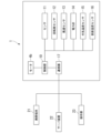
- FIG. 1 is a block diagram showing the configuration of a carbon dioxide recovery system according to Embodiment 1.
- FIG. It is a graph showing an example of a change in temperature difference between the surface temperature of an adsorbent and the temperature of outside air.
- It is a schematic diagram showing the composition of the carbon dioxide collection system concerning a modification.
- FIG. 1 is a schematic diagram showing the configuration of a carbon dioxide recovery system 1 according to the first embodiment.
- the carbon dioxide recovery system 1 includes an adsorbent 2, a holding section 3, and an outdoor unit 4.
- the outdoor unit 4 is part of the heat pump device H and is used together with the indoor unit 5.
- the heat pump device H may be, for example, an air conditioner.
- the outdoor unit 4 and the indoor unit 5 are connected by a pipe P or the like for circulating refrigerant.
- the outdoor unit 4 has a blower 4a (fan).
- the blower 4a has a motor 4b (see FIG. 2).
- the outdoor unit 4 includes a compressor, a heat exchanger, etc. (not shown).
- the adsorbent 2 includes a material capable of adsorbing carbon dioxide.
- materials capable of adsorbing carbon dioxide include amines, zeolites, silica gel, diatomaceous earth, alumina, and activated carbon. A plurality of materials may be selected from those listed above, or materials other than those listed above may be employed.
- the adsorbent 2 shown in FIG. 1 has a rectangular parallelepiped shape (block shape), the shape of the adsorbent 2 can be changed as appropriate.
- the adsorbent 2 may be granular (eg, bead-like (spherical), pellet-like (cylindrical)).
- powdered adsorbent 2 may be used.
- the powdered adsorbent 2 may be supported on the surface of the base material.
- the base material may have a honeycomb shape, for example.
- the adsorbent 2 may be filled in a breathable container (filling container), and this container may be held by the holding section 3.
- the adsorbent 2 is preferably made of a material that allows carbon dioxide to be separated when the adsorbent 2 adsorbing carbon dioxide is heated (eg, 60 to 120° C.). The heating temperature is appropriately changed depending on the specific material of the adsorbent 2.
- the holding part 3 is capable of holding the adsorbent 2 at a position where it receives the airflow generated by the blower 4a of the outdoor unit 4.
- the holding part 3 is arranged downstream of the blower 4a.
- the holding part 3 may be arranged upstream of the blower 4a.
- the holding part 3 in this embodiment is a box-shaped container (holding container) that can accommodate the adsorbent 2, and has air permeability. Further, the holding portion 3 has an opening through which the adsorbent 2 passes. Although the opening in FIG. 1 faces upward, the position of the opening can be changed. Moreover, the holding part 3 may have a door that can be opened and closed instead of the opening. In this case, the adsorbent 2 can be stored in the holding part 3 or taken out from the holding part 3 by opening and closing the door.
- the structure for providing breathability to the holding part 3 can be changed as appropriate, for example, all or part of the holding part 3 may be mesh-shaped. As an example, when the adsorbent 2 is granular, a plurality of holes smaller than the particle size of the adsorbent 2 may be formed in the holding part 3.
- the material of the holding part 3 can be changed as appropriate, and may be metal or resin. Structures other than those described above can also be adopted as the holding portion 3.
- the carbon dioxide recovery system 1 includes a sensor 11 that detects whether or not the adsorbent 2 is held at a position receiving the airflow from the blower 4a.
- the sensor 11 may be of a weight type.
- the "weight method” is a method of detecting the presence of the adsorbent 2 by using the weight of the adsorbent 2 itself or the weight of an object containing the adsorbent 2.
- the "object containing the adsorbent 2" is, for example, the holding part 3 containing the adsorbent 2.
- “Using weight” includes not only measuring weight but also pressing down a mechanical switch based on weight.
- the weight-type sensor 11 may be arranged at the bottom inside the holding part 3, as shown in FIG.
- the senor 11 is not limited to the weight type.
- the sensor 11 may be of an optical type.
- the optical sensor 11 has a light emitting section and a light receiving section.
- the optical sensor 11 can detect the presence or absence of the adsorbent 2 based on whether the light emitted from the emitting part is detected by the light receiving part.
- the light receiving section may be arranged at a position where it receives the light emitted from the emitting section and reflected by the adsorbent 2. In this case, when the light receiving section detects the light emitted by the emitting section, it is determined that the adsorbent 2 is present.
- the light receiving section and the emitting section may be arranged to face each other, and the adsorbent 2 may be held between the light receiving section and the emitting section.
- the adsorbent 2 may be held between the light receiving section and the emitting section.
- FIG. 2 is a block diagram showing a configuration example of the carbon dioxide recovery system 1.
- the carbon dioxide recovery system 1 includes a control unit 10, the sensor 11, a rotation speed sensor 12, a wind speed sensor 13, a wattmeter 14, an outside temperature sensor 15, and a surface temperature sensor 16. and a communication device 17.
- the control unit 10 is connected to each component 11-17. Further, the control unit 10 is connected to a motor 4b included in the blower 4a.
- the carbon dioxide recovery system 1 may not include some or all of the rotation speed sensor 12, wind speed sensor 13, wattmeter 14, outside air temperature sensor 15, surface temperature sensor 16, and communication device 17. good.
- the control unit 10 controls at least the motor 4b of the blower 4a based on the results detected or measured by the sensor 11, rotation speed sensor 12, etc.
- the control unit 10 may control components other than the blower 4a.
- the control unit 10 may control a compressor or the like included in the heat pump device H.
- a processor such as a CPU (Central Processing Unit) can be used.
- the rotation speed sensor 12 measures the rotation speed of the blower 4a.
- the measurement results obtained by the rotation speed sensor 12 are input to the control section 10 .
- the control unit 10 may control the blower 4a based on the measurement result by the rotation speed sensor 12.
- the wind speed sensor 13 measures the wind speed of the airflow generated by the blower 4a and received by the adsorbent 2.
- the measurement results by the wind speed sensor 13 are input to the control unit 10.
- the control unit 10 may control the blower 4a based on the measurement result by the wind speed sensor 13.
- the wattmeter 14 measures the power consumption of the motor 4b of the blower 4a.
- the measurement results obtained by the wattmeter 14 are input to the control section 10 .
- the control unit 10 may control the blower 4a based on the measurement result by the wattmeter 14.
- the outside air temperature sensor 15 measures the outside air temperature around the adsorbent 2.
- the outside air temperature sensor 15 may measure the temperature inside the holding part 3 or may measure the temperature outside the holding part 3. If the outdoor unit 4 has a temperature sensor, the temperature sensor may be used as the outside air temperature sensor 15.
- an electric thermometer can be used as the outside air temperature sensor 15.
- the surface temperature sensor 16 measures the surface temperature of the adsorbent 2.
- a non-contact thermometer for example, an infrared thermometer
- the measurement methods of the outside air temperature sensor 15 and the surface temperature sensor 16 can be changed as appropriate. Measurement results from the outside air temperature sensor 15 and the surface temperature sensor 16 are input to the control unit 10.
- the control unit 10 may control the blower 4a based on the measurement results by the outside air temperature sensor 15 and the surface temperature sensor 16.
- the communication device 17 communicates with the outside (for example, the mobile terminal 21, the server device 22, the operation unit 23, etc.) under the control of the control unit 10.
- the mobile terminal 21 is, for example, a smartphone, a notebook PC, a tablet terminal, or the like.
- An application or the like for operating the heat pump device H may be installed on the mobile terminal 21.
- the server device 22 has a processing section, a storage section, a communication section, etc., and can process and store information.
- the server device 22 may be, for example, a cloud server. Further, the server device 22 may be installed in a data center.
- the operation unit 23 is a part for operating the heat pump device H. For example, when the heat pump device H is an air conditioner, the operation unit 23 is a remote controller or the like that communicates with the indoor unit 5. An example of control performed by the control unit 10 will be described below.
- the blower 4a When the heat pump device H is not operating (for example, when neither heating operation nor cooling operation is performed), the blower 4a is normally stopped. Therefore, the airflow does not hit the adsorbent 2, and the carbon dioxide adsorption efficiency decreases. Therefore, the control section 10 drives the blower 4a when the sensor 11 detects that the adsorbent 2 is held in the holding section 3 while the blower 4a is stopped. Thereby, even when the heat pump device H is not in operation, it is possible to apply airflow to the adsorbent 2 and promote adsorption of carbon dioxide.
- the blower 4a is normally driven to apply airflow to the heat exchanger of the outdoor unit 4.
- the airflow generated by the blower 4a is blocked by the adsorbent 2.
- the control part 10 increases the rotation speed of the blower 4a. This makes it possible to achieve both performance of the heat pump device H and carbon dioxide recovery efficiency.
- control unit 10 may output a notification signal in a situation where it is estimated that carbon dioxide has been sufficiently adsorbed by the adsorbent 2.
- the "notification signal” is a signal for notifying the user etc. of the time to replace the adsorbent 2.
- the control unit 10 outputs a notification signal to the mobile terminal 21, the server device 22, the operation unit 23, etc. via the communication device 17.
- the mobile terminal 21 When the mobile terminal 21 receives the notification signal, it may display information (message, icon, etc.) prompting replacement of the adsorbent 2 on the application screen or the like.
- the server device 22 When the server device 22 receives the notification signal, the server device 22 may cause a device connected to the server device 22 to display information prompting replacement of the adsorbent 2.
- the operation unit 23 may display information prompting the replacement of the adsorbent 2 on a display unit (such as a liquid crystal screen) included in the operation unit 23.
- a display unit such as a liquid crystal screen
- notifying the time to replace the adsorbent 2 includes notifying that the time for replacement has already arrived, but also notifying that the time for replacement will come after a predetermined period (for example, several days). Also included.
- the conditions under which the control unit 10 outputs the notification signal can be set as appropriate.
- the sensor 11 is of a weight type
- a change in the weight of the adsorbent 2 can be obtained based on the detection result by the sensor 11.
- the weight of the adsorbent 2 increases.
- the adsorption rate of carbon dioxide decreases. That is, based on the weight change of the adsorbent 2, it is possible to estimate the amount of room the adsorbent 2 has to adsorb carbon dioxide.
- control unit 10 may output a notification signal when the increase in the weight of the adsorbent 2 exceeds a threshold value.
- the threshold value may be set based on the results obtained through preliminary experiments or the like of the weight change when the adsorbent 2 adsorbs carbon dioxide.
- the control unit 10 By outputting a notification signal by the control unit 10 when the conditions are met, it is possible to prompt the user or the like to replace the adsorbent 2. Then, it is possible to prevent the adsorbent 2 whose adsorption efficiency has decreased from being continuously held in the holding part 3.
- the person to be urged to replace the adsorbent 2 is not limited to the user of the heat pump device H, but may be, for example, the manager of the building where the heat pump device H is installed, the maintenance company of the heat pump device H, or the like.
- the adsorption efficiency of carbon dioxide by the adsorbent 2 is correlated with the amount of airflow passing through the adsorbent 2 (hereinafter referred to as cumulative airflow). Specifically, in a situation where the adsorbent 2 has not yet sufficiently adsorbed carbon dioxide, the adsorption of carbon dioxide progresses as the airflow hits the adsorbent 2. However, as the cumulative air volume increases, the adsorption of carbon dioxide by the adsorbent 2 approaches a saturated state, and the adsorption efficiency gradually decreases. In other words, based on the cumulative amount of air passing through the adsorbent 2, it is possible to estimate the amount of room the adsorbent 2 has to adsorb carbon dioxide.
- control unit 10 may output a notification signal when the cumulative amount of air passing through the adsorbent 2 exceeds a threshold value.
- This threshold value may be set based on the results obtained through preliminary experiments or the like of changes in the amount of carbon dioxide adsorbed when the adsorbent 2 is continuously exposed to an air flow.
- the cumulative air volume that has passed through the adsorbent 2 is calculated based on, for example, the length of time during which the sensor 11 detects the presence of the adsorbent 2, the rotation speed of the blower 4a measured by the rotation speed sensor 12, and the rotation speed of the blower 4a. It can be estimated based on the driving time. Alternatively, the cumulative air volume may be estimated based on the length of time during which the presence of the adsorbent 2 was detected by the sensor 11 and the measurement result by the wind speed sensor 13. Alternatively, the cumulative air volume may be estimated based on the length of time during which the presence of the adsorbent 2 was detected by the sensor 11 and the measurement result by the wattmeter 14. Since the power consumption of the blower 4a is correlated with the amount of drive of the blower 4a (the product of the drive time and the number of rotations), the cumulative air volume can be estimated using the measurement results of the wattmeter 14.
- the surface temperature of the adsorbent 2 changes.
- the surface temperature of the adsorbent 2 increases due to reaction heat accompanying adsorption of carbon dioxide. Therefore, based on the temperature change of the adsorbent 2, it is possible to estimate whether or not adsorption of carbon dioxide in the adsorbent 2 is progressing.
- the surface temperature of the adsorbent 2 also changes depending on the temperature of the outside air. For this reason, it is preferable to use the difference between the surface temperature of the adsorbent 2 and the temperature of the outside air (hereinafter simply referred to as "temperature difference"). By using this temperature difference, it is possible to eliminate the influence of temperature changes in the outside air.
- FIG. 3 is a graph showing an example of changes in temperature difference.
- the horizontal axis represents the time during which the adsorbent 2 is held in the holding part 3, and the vertical axis represents the above-described temperature difference.
- the carbon dioxide recovery system 1 includes the blower 4a, the holding part 3 that holds the adsorbent 2 capable of adsorbing carbon dioxide at a position receiving the airflow of the blower 4a, and the holding part 3 that holds the adsorbent 2 capable of adsorbing carbon dioxide. It includes a sensor 11 that detects that the adsorbent 2 is held in the section 3, and a control section 10 that controls the blower 4a. Then, when the sensor 11 detects that the adsorbent 2 is held in the holding section 3 while the blower 4a is stopped, the control section 10 drives the blower 4a.
- the airflow can be applied to the adsorbent 2, and a decrease in carbon dioxide recovery efficiency can be suppressed.
- the outdoor unit 4 can be used to recover carbon dioxide even in seasons when the operating rate is low (for example, spring and autumn in Japan).
- the holding section 3 in this embodiment is a container with air permeability. This stabilizes the position at which the adsorbent 2 is held, so that the sensor 11 can detect the adsorbent 2 more reliably.
- the blower 4a in this embodiment is a fan included in the outdoor unit 4 of the heat pump device H. Even if the fan of the outdoor unit 4 is driven when the heat pump device H is not operating, there is little influence of noise into the room. Therefore, recovery of carbon dioxide can be promoted while suppressing the impact on living spaces and the like.
- the control part 10 may increase the rotation speed of the blower 4a. good. In this case, it is possible to suppress a decrease in the performance of the heat pump device H due to the airflow of the blower 4a being blocked by the adsorbent 2.
- the sensor 11 may detect that the adsorbent 2 is held in the holding part 3 by weight. That is, the sensor 11 may be of a weight type. Then, the control unit 10 may output a notification signal to notify the time to replace the adsorbent 2 based on the amount of increase in weight detected by the sensor 11. In this case, it is possible to avoid leaving the adsorbent 2 that has completed adsorption of carbon dioxide as it is.
- the sensor 11 may be an optical sensor. In this case, the sensor 11 can be downsized.
- control unit 10 may estimate the cumulative air volume that has passed through the adsorbent 2 based on the detection result by the sensor 11 and the measurement result by the rotation speed sensor 12 that measures the rotation speed of the blower 4a.
- control unit 10 may estimate the cumulative air volume based on the detection result by the sensor 11 and the measurement result by the wind speed sensor 13 that measures the wind speed of the airflow passing through the adsorbent 2.
- control unit 10 may estimate the cumulative air volume based on the detection result by the sensor 11 and the wattmeter 14 that measures the power consumption of the motor 4b of the blower 4a.
- control unit 10 may output a notification signal to notify the time to replace the adsorbent 2 based on the trial calculation result of the cumulative air volume.
- the control unit 10 may calculate the cumulative air volume using each of the rotation speed sensor 12, the wind speed sensor 13, and the wattmeter 14, and output a notification signal when the result of any of the calculations satisfies a condition. Further, the control unit 10 may output the notification signal based on a change in the difference between the outside air temperature sensor 15 that measures the outside air temperature and the surface temperature sensor 16 that measures the surface temperature of the adsorbent 2. .
- the carbon dioxide recovery system 1 may include a communication device 17.
- the communication device 17 may transmit the notification signal output by the control unit 10 to any or all of the mobile terminal 21, the server device 22, and the operation unit 23.
- the user, administrator, maintenance company, etc. of the heat pump device H can be urged to replace the adsorbent 2.
- the blower 4a is a fan of the outdoor unit 4.
- a ventilation fan 31 provided in a building 30 may be used as the blower.
- a holding portion 33 may be provided at the bottom of a hood 32 that covers the ventilation fan 31 from the outside of the building 30.
- the holding part 33 shown in FIG. 4 extends substantially horizontally from the wall surface of the building 30, and can hold the adsorbent 2 on the upper part of the holding part 33.
- the airflow that the ventilation fan 31 draws into the building 30 or the airflow that the ventilation fan 31 exhausts from the building 30 passes through the lower part of the hood 32.
- the holding part 33 may have a ventilation hole 33a.
- the holding portion 33 is provided with air permeability, making it easier to apply airflow to the adsorbent 2.
- Other configurations may be adopted to provide the holding portion 33 with air permeability.
- a sensor 11 is provided near the wall surface of the building 30 to detect that the adsorbent 2 is held in the holding part 33.
- a control unit 10 (not shown) is connected to the ventilation fan 31.
- the carbon dioxide recovery system shown in FIG. 4 also includes a blower (ventilation fan 31), a holding section 33 that holds an adsorbent 2 capable of adsorbing carbon dioxide at a position receiving the airflow of the blower, and a holding section 33 that holds an adsorbent 2 that can adsorb carbon dioxide. It includes a sensor 11 that detects that it is being held, and a control unit 10 that controls the blower.
- control unit 10 drives the blower when the sensor 11 detects that the adsorbent 2 is held in the holding portion 33 while the blower is stopped.
- control unit 10 described above has a computer system inside. Then, a program for realizing the functions of each component of the carbon dioxide recovery system 1 described above is recorded on a computer-readable recording medium, and the program recorded on the recording medium is read into the computer system and executed. Accordingly, the processing in the control unit 10 described above may be performed. Furthermore, hardware other than the control unit 10 may perform the above-described processing.
- reading a program recorded on a recording medium into a computer system and executing it includes installing the program on the computer system.
- the "computer system” herein includes an OS and hardware such as peripheral devices.
- a "computer system” may include a plurality of computer devices connected via the Internet or a network including a communication line such as a WAN, LAN, or a dedicated line.
- a communication line such as a WAN, LAN, or a dedicated line.
- computer-readable recording medium refers to portable media such as flexible disks, magneto-optical disks, ROMs, and CD-ROMs, and storage devices such as hard disks built into computer systems.
- the recording medium storing the program may be a non-transitory recording medium such as a CD-ROM.
- the recording medium also includes a recording medium provided internally or externally that can be accessed from the distribution server to distribute the program.
- the program may be divided into a plurality of parts, downloaded at different times, and then combined into each component of the carbon dioxide recovery system 1.
- the distribution server that distributes each of the divided programs may be May be different.
- a "computer-readable recording medium” refers to a storage medium that retains a program for a certain period of time, such as volatile memory (RAM) inside a computer system that is a server or client when a program is transmitted via a network. This shall also include things.
- the above-mentioned program may be for realizing a part of the above-mentioned functions.
- it may be a so-called difference file (difference program) that can realize the above-mentioned functions in combination with a program already recorded in the computer system.
Landscapes
- Chemical & Material Sciences (AREA)
- Engineering & Computer Science (AREA)
- Chemical Kinetics & Catalysis (AREA)
- General Chemical & Material Sciences (AREA)
- Analytical Chemistry (AREA)
- Oil, Petroleum & Natural Gas (AREA)
- Combustion & Propulsion (AREA)
- Mechanical Engineering (AREA)
- General Engineering & Computer Science (AREA)
- Organic Chemistry (AREA)
- Inorganic Chemistry (AREA)
- Separation Of Gases By Adsorption (AREA)
- Carbon And Carbon Compounds (AREA)
Abstract
Description
図1は、実施の形態1に係る二酸化炭素回収システム1の構成を示す概略図である。図1に示すように、二酸化炭素回収システム1は、吸着剤2と、保持部3と、室外機4と、を備えている。室外機4は、ヒートポンプ装置Hの一部であり、室内機5とともに用いられる。ヒートポンプ装置Hは、例えば空気調和機であってもよい。室外機4および室内機5は、冷媒を循環させるためのパイプP等で接続されている。室外機4は、送風機4a(ファン)を有している。送風機4aはモータ4b(図2参照)を有している。また、室外機4は、不図示の圧縮器、熱交換器等を有している。
以下、制御部10が行う制御の例について説明する。
図4に示す二酸化炭素回収システムも、送風機(換気扇31)と、送風機の気流を受ける位置で、二酸化炭素を吸着可能な吸着剤2を保持する保持部33と、保持部33に吸着剤2が保持されていることを検知するセンサ11と、送風機を制御する制御部10と、を備える。そして制御部10は、送風機が停止している状態で、保持部33に吸着剤2が保持されていることをセンサ11が検知したときに、送風機を駆動させる。このような構成によっても、実施の形態1と同様に、吸着剤2による二酸化炭素の吸着効率の低下を抑制することができる。
Claims (11)
- 送風機と、
前記送風機の気流を受ける位置で、二酸化炭素を吸着可能な吸着剤を保持する保持部と、
前記保持部に前記吸着剤が保持されていることを検知するセンサと、
前記送風機を制御する制御部と、を備え、
前記制御部は、前記送風機が停止している状態で、前記保持部に前記吸着剤が保持されていることを前記センサが検知したときに、前記送風機を駆動させる、二酸化炭素回収システム。 - 前記保持部は、通気性を有する容器である、請求項1に記載の二酸化炭素回収システム。
- 前記送風機は、ヒートポンプ装置の室外機が有するファンである、請求項1または2に記載の二酸化炭素回収システム。
- 前記制御部は、前記ヒートポンプ装置が稼働している状態で、前記保持部に前記吸着剤が保持されていることを前記センサが検知したときに、前記送風機の回転数を増加させる、請求項3に記載の二酸化炭素回収システム。
- 前記センサは、前記保持部に前記吸着剤が保持されていることを重量で検知し、
前記制御部は、前記センサが検知した重量の増加量に基づいて、前記吸着剤の交換時期を報知させる報知信号を出力する、請求項1から4のいずれか1項に記載の二酸化炭素回収システム。 - 前記センサは、光学式センサである、請求項1から4のいずれか1項に記載の二酸化炭素回収システム。
- 前記送風機の回転数を計測する回転数センサをさらに備え、
前記制御部は、前記センサによる検知結果と、前記回転数センサによる計測結果と、に基づき、前記吸着剤を通過した累積風量を試算し、前記累積風量に基づいて、前記吸着剤の交換時期を報知させる報知信号を出力する、請求項1から6のいずれか1項に記載の二酸化炭素回収システム。 - 前記吸着剤を通過する気流の風速を計測する風速センサをさらに備え、
前記制御部は、前記センサによる検知結果と、前記風速センサによる計測結果と、に基づき、前記吸着剤を通過した累積風量を試算し、前記累積風量に基づいて、前記吸着剤の交換時期を報知させる報知信号を出力する、請求項1から7のいずれか1項に記載の二酸化炭素回収システム。 - 前記送風機が有するモータの消費電力を計測する電力計をさらに備え、
前記制御部は、前記センサによる検知結果と、前記電力計による計測結果と、に基づき、前記吸着剤を通過した累積風量を試算し、前記累積風量に基づいて、前記吸着剤の交換時期を報知させる報知信号を出力する、請求項1から8のいずれか1項に記載の二酸化炭素回収システム。 - 外気の温度を計測する外気温度センサと、
前記吸着剤の表面温度を計測する表面温度センサと、をさらに備え、
前記制御部は、前記外気の温度と前記吸着剤の表面温度との差分の変化に基づいて、前記吸着剤の交換時期を報知させる報知信号を出力する、請求項1から9のいずれか1項に記載の二酸化炭素回収システム。 - 通信器をさらに備え、
前記通信器は、前記制御部が出力した前記報知信号を、携帯端末、サーバ装置、およびヒートポンプ装置の操作部のうち少なくとも1つに伝達する、請求項5、7から9のいずれか1項に記載の二酸化炭素回収システム。
Priority Applications (5)
| Application Number | Priority Date | Filing Date | Title |
|---|---|---|---|
| JP2023520290A JP7301255B1 (ja) | 2022-07-15 | 2022-07-15 | 二酸化炭素回収システム |
| EP22951180.3A EP4556098A4 (en) | 2022-07-15 | 2022-07-15 | CARBON DIOXIDE COLLECTION SYSTEM |
| CN202280097036.9A CN119604351A (zh) | 2022-07-15 | 2022-07-15 | 二氧化碳回收系统 |
| PCT/JP2022/027811 WO2024013971A1 (ja) | 2022-07-15 | 2022-07-15 | 二酸化炭素回収システム |
| US18/874,593 US20250367590A1 (en) | 2022-07-15 | 2022-07-15 | Carbon-dioxide recovery system |
Applications Claiming Priority (1)
| Application Number | Priority Date | Filing Date | Title |
|---|---|---|---|
| PCT/JP2022/027811 WO2024013971A1 (ja) | 2022-07-15 | 2022-07-15 | 二酸化炭素回収システム |
Publications (1)
| Publication Number | Publication Date |
|---|---|
| WO2024013971A1 true WO2024013971A1 (ja) | 2024-01-18 |
Family
ID=86938652
Family Applications (1)
| Application Number | Title | Priority Date | Filing Date |
|---|---|---|---|
| PCT/JP2022/027811 Ceased WO2024013971A1 (ja) | 2022-07-15 | 2022-07-15 | 二酸化炭素回収システム |
Country Status (5)
| Country | Link |
|---|---|
| US (1) | US20250367590A1 (ja) |
| EP (1) | EP4556098A4 (ja) |
| JP (1) | JP7301255B1 (ja) |
| CN (1) | CN119604351A (ja) |
| WO (1) | WO2024013971A1 (ja) |
Cited By (1)
| Publication number | Priority date | Publication date | Assignee | Title |
|---|---|---|---|---|
| GB2637385A (en) * | 2024-01-22 | 2025-07-23 | Global Carbon Solutions Ltd | Improved carbon filter system |
Citations (8)
| Publication number | Priority date | Publication date | Assignee | Title |
|---|---|---|---|---|
| JP2000325460A (ja) * | 1999-05-21 | 2000-11-28 | Matsushita Electric Ind Co Ltd | 脱臭装置 |
| JP2007330969A (ja) * | 2003-03-04 | 2007-12-27 | Osaka Gas Co Ltd | ガス吸着処理システムの破過検知装置 |
| JP2013022577A (ja) * | 2011-07-26 | 2013-02-04 | Nippon Telegr & Teleph Corp <Ntt> | 二酸化炭素回収方法および装置 |
| JP2014024715A (ja) * | 2012-07-27 | 2014-02-06 | Nippon Telegr & Teleph Corp <Ntt> | 二酸化炭素回収方法および装置 |
| WO2017138226A1 (ja) * | 2016-02-12 | 2017-08-17 | 三菱電機株式会社 | 循環配管システム及び二酸化炭素含有水供給システム |
| US20200206675A1 (en) * | 2018-12-28 | 2020-07-02 | Samsung Electronics Co., Ltd. | Air conditioning device and control method thereof |
| JP2020131166A (ja) | 2019-02-25 | 2020-08-31 | 株式会社神鋼環境ソリューション | 二酸化炭素吸着設備 |
| JP2021020178A (ja) * | 2019-07-30 | 2021-02-18 | 株式会社豊田中央研究所 | ガス分離装置およびガス分離方法 |
Family Cites Families (4)
| Publication number | Priority date | Publication date | Assignee | Title |
|---|---|---|---|---|
| JP2019090546A (ja) * | 2017-11-10 | 2019-06-13 | 三菱電機株式会社 | 送風装置、空気調和装置および換気システム |
| JP6709773B2 (ja) * | 2017-11-30 | 2020-06-17 | 本田技研工業株式会社 | 車両用空気浄化装置 |
| KR102540631B1 (ko) * | 2020-12-23 | 2023-06-12 | 한국에너지기술연구원 | 차량 실내 이산화탄소 제거 장치 및 그 재생과 제어 방법 |
| CN113405164B (zh) * | 2021-06-16 | 2022-08-19 | 重庆海尔空调器有限公司 | 用于控制二氧化碳吸附模块的方法、装置和智能空调 |
-
2022
- 2022-07-15 WO PCT/JP2022/027811 patent/WO2024013971A1/ja not_active Ceased
- 2022-07-15 CN CN202280097036.9A patent/CN119604351A/zh active Pending
- 2022-07-15 US US18/874,593 patent/US20250367590A1/en active Pending
- 2022-07-15 EP EP22951180.3A patent/EP4556098A4/en active Pending
- 2022-07-15 JP JP2023520290A patent/JP7301255B1/ja active Active
Patent Citations (8)
| Publication number | Priority date | Publication date | Assignee | Title |
|---|---|---|---|---|
| JP2000325460A (ja) * | 1999-05-21 | 2000-11-28 | Matsushita Electric Ind Co Ltd | 脱臭装置 |
| JP2007330969A (ja) * | 2003-03-04 | 2007-12-27 | Osaka Gas Co Ltd | ガス吸着処理システムの破過検知装置 |
| JP2013022577A (ja) * | 2011-07-26 | 2013-02-04 | Nippon Telegr & Teleph Corp <Ntt> | 二酸化炭素回収方法および装置 |
| JP2014024715A (ja) * | 2012-07-27 | 2014-02-06 | Nippon Telegr & Teleph Corp <Ntt> | 二酸化炭素回収方法および装置 |
| WO2017138226A1 (ja) * | 2016-02-12 | 2017-08-17 | 三菱電機株式会社 | 循環配管システム及び二酸化炭素含有水供給システム |
| US20200206675A1 (en) * | 2018-12-28 | 2020-07-02 | Samsung Electronics Co., Ltd. | Air conditioning device and control method thereof |
| JP2020131166A (ja) | 2019-02-25 | 2020-08-31 | 株式会社神鋼環境ソリューション | 二酸化炭素吸着設備 |
| JP2021020178A (ja) * | 2019-07-30 | 2021-02-18 | 株式会社豊田中央研究所 | ガス分離装置およびガス分離方法 |
Non-Patent Citations (1)
| Title |
|---|
| See also references of EP4556098A4 |
Cited By (1)
| Publication number | Priority date | Publication date | Assignee | Title |
|---|---|---|---|---|
| GB2637385A (en) * | 2024-01-22 | 2025-07-23 | Global Carbon Solutions Ltd | Improved carbon filter system |
Also Published As
| Publication number | Publication date |
|---|---|
| US20250367590A1 (en) | 2025-12-04 |
| EP4556098A4 (en) | 2025-12-31 |
| CN119604351A (zh) | 2025-03-11 |
| EP4556098A1 (en) | 2025-05-21 |
| JP7301255B1 (ja) | 2023-06-30 |
| JPWO2024013971A1 (ja) | 2024-01-18 |
Similar Documents
| Publication | Publication Date | Title |
|---|---|---|
| EP3867577B1 (en) | Air conditioning device and control method thereof | |
| US10598398B2 (en) | Energy recovery ventilation smoke evacuation | |
| JP2014115012A (ja) | ファン制御装置 | |
| CN110107984A (zh) | 空调的冷媒泄漏控制方法、系统及空调 | |
| JP2011214740A (ja) | 吸脱着装置および吸着質交換状態監視方法 | |
| CN103712306A (zh) | 换气系统、换气方法及换气控制装置 | |
| CN110044024B (zh) | 空调的风机控制方法、系统及空调 | |
| JPWO2020255875A5 (ja) | ||
| CN107883532A (zh) | 新风机与空调联动系统及其控制方法、装置及存储介质 | |
| JP7301255B1 (ja) | 二酸化炭素回収システム | |
| JP5691040B2 (ja) | 調湿システム及びその運用監視方法 | |
| US10488070B1 (en) | Systems and methods for controlling an intake fan | |
| CN206312040U (zh) | 一种便于维修的计算机主机箱 | |
| KR102281604B1 (ko) | 지하공간 환기 시스템의 군집제어 시스템 및 그 방법 | |
| JP2011169562A5 (ja) | ||
| CN106662354B (zh) | 一种带降尘排烟功能的空调系统 | |
| CN206504406U (zh) | 一种具有空气净化功能的风扇 | |
| CN201983404U (zh) | 空调出风装置 | |
| JPWO2024013971A5 (ja) | ||
| CN213957296U (zh) | 一种多功能气体监测装置 | |
| CN103869850A (zh) | 智能湿度计、湿度检测方法、湿度控制方法和系统 | |
| CN110398044B (zh) | 新风机的控制方法、系统及新风机 | |
| JP5888907B2 (ja) | 建物、火災検知システム、データセンタ、および火災検知の方法 | |
| TWM531566U (zh) | 居家防護系統 | |
| CN206813317U (zh) | 一种用于空气检测无人机 |
Legal Events
| Date | Code | Title | Description |
|---|---|---|---|
| WWE | Wipo information: entry into national phase |
Ref document number: 2023520290 Country of ref document: JP |
|
| 121 | Ep: the epo has been informed by wipo that ep was designated in this application |
Ref document number: 22951180 Country of ref document: EP Kind code of ref document: A1 |
|
| WWE | Wipo information: entry into national phase |
Ref document number: 202280097036.9 Country of ref document: CN |
|
| WWE | Wipo information: entry into national phase |
Ref document number: 18874593 Country of ref document: US |
|
| WWE | Wipo information: entry into national phase |
Ref document number: 2022951180 Country of ref document: EP |
|
| NENP | Non-entry into the national phase |
Ref country code: DE |
|
| ENP | Entry into the national phase |
Ref document number: 2022951180 Country of ref document: EP Effective date: 20250217 |
|
| WWP | Wipo information: published in national office |
Ref document number: 202280097036.9 Country of ref document: CN |
|
| WWP | Wipo information: published in national office |
Ref document number: 2022951180 Country of ref document: EP |
|
| WWP | Wipo information: published in national office |
Ref document number: 18874593 Country of ref document: US |