WO2024014007A1 - 転がり軸受及びその製造方法 - Google Patents
転がり軸受及びその製造方法 Download PDFInfo
- Publication number
- WO2024014007A1 WO2024014007A1 PCT/JP2022/032467 JP2022032467W WO2024014007A1 WO 2024014007 A1 WO2024014007 A1 WO 2024014007A1 JP 2022032467 W JP2022032467 W JP 2022032467W WO 2024014007 A1 WO2024014007 A1 WO 2024014007A1
- Authority
- WO
- WIPO (PCT)
- Prior art keywords
- film
- raceway surface
- crystallite size
- thickness
- oxide film
- Prior art date
- Legal status (The legal status is an assumption and is not a legal conclusion. Google has not performed a legal analysis and makes no representation as to the accuracy of the status listed.)
- Ceased
Links
Images





Classifications
-
- C—CHEMISTRY; METALLURGY
- C23—COATING METALLIC MATERIAL; COATING MATERIAL WITH METALLIC MATERIAL; CHEMICAL SURFACE TREATMENT; DIFFUSION TREATMENT OF METALLIC MATERIAL; COATING BY VACUUM EVAPORATION, BY SPUTTERING, BY ION IMPLANTATION OR BY CHEMICAL VAPOUR DEPOSITION, IN GENERAL; INHIBITING CORROSION OF METALLIC MATERIAL OR INCRUSTATION IN GENERAL
- C23C—COATING METALLIC MATERIAL; COATING MATERIAL WITH METALLIC MATERIAL; SURFACE TREATMENT OF METALLIC MATERIAL BY DIFFUSION INTO THE SURFACE, BY CHEMICAL CONVERSION OR SUBSTITUTION; COATING BY VACUUM EVAPORATION, BY SPUTTERING, BY ION IMPLANTATION OR BY CHEMICAL VAPOUR DEPOSITION, IN GENERAL
- C23C8/00—Solid state diffusion of only non-metal elements into metallic material surfaces; Chemical surface treatment of metallic material by reaction of the surface with a reactive gas, leaving reaction products of surface material in the coating, e.g. conversion coatings, passivation of metals
- C23C8/06—Solid state diffusion of only non-metal elements into metallic material surfaces; Chemical surface treatment of metallic material by reaction of the surface with a reactive gas, leaving reaction products of surface material in the coating, e.g. conversion coatings, passivation of metals using gases
- C23C8/08—Solid state diffusion of only non-metal elements into metallic material surfaces; Chemical surface treatment of metallic material by reaction of the surface with a reactive gas, leaving reaction products of surface material in the coating, e.g. conversion coatings, passivation of metals using gases only one element being applied
- C23C8/10—Oxidising
- C23C8/12—Oxidising using elemental oxygen or ozone
- C23C8/14—Oxidising of ferrous surfaces
-
- F—MECHANICAL ENGINEERING; LIGHTING; HEATING; WEAPONS; BLASTING
- F16—ENGINEERING ELEMENTS AND UNITS; GENERAL MEASURES FOR PRODUCING AND MAINTAINING EFFECTIVE FUNCTIONING OF MACHINES OR INSTALLATIONS; THERMAL INSULATION IN GENERAL
- F16C—SHAFTS; FLEXIBLE SHAFTS; ELEMENTS OR CRANKSHAFT MECHANISMS; ROTARY BODIES OTHER THAN GEARING ELEMENTS; BEARINGS
- F16C19/00—Bearings with rolling contact, for exclusively rotary movement
- F16C19/02—Bearings with rolling contact, for exclusively rotary movement with bearing balls essentially of the same size in one or more circular rows
- F16C19/10—Bearings with rolling contact, for exclusively rotary movement with bearing balls essentially of the same size in one or more circular rows for axial load mainly
-
- F—MECHANICAL ENGINEERING; LIGHTING; HEATING; WEAPONS; BLASTING
- F16—ENGINEERING ELEMENTS AND UNITS; GENERAL MEASURES FOR PRODUCING AND MAINTAINING EFFECTIVE FUNCTIONING OF MACHINES OR INSTALLATIONS; THERMAL INSULATION IN GENERAL
- F16C—SHAFTS; FLEXIBLE SHAFTS; ELEMENTS OR CRANKSHAFT MECHANISMS; ROTARY BODIES OTHER THAN GEARING ELEMENTS; BEARINGS
- F16C19/00—Bearings with rolling contact, for exclusively rotary movement
- F16C19/52—Bearings with rolling contact, for exclusively rotary movement with devices affected by abnormal or undesired conditions
-
- F—MECHANICAL ENGINEERING; LIGHTING; HEATING; WEAPONS; BLASTING
- F16—ENGINEERING ELEMENTS AND UNITS; GENERAL MEASURES FOR PRODUCING AND MAINTAINING EFFECTIVE FUNCTIONING OF MACHINES OR INSTALLATIONS; THERMAL INSULATION IN GENERAL
- F16C—SHAFTS; FLEXIBLE SHAFTS; ELEMENTS OR CRANKSHAFT MECHANISMS; ROTARY BODIES OTHER THAN GEARING ELEMENTS; BEARINGS
- F16C33/00—Parts of bearings; Special methods for making bearings or parts thereof
- F16C33/30—Parts of ball or roller bearings
- F16C33/32—Balls
-
- F—MECHANICAL ENGINEERING; LIGHTING; HEATING; WEAPONS; BLASTING
- F16—ENGINEERING ELEMENTS AND UNITS; GENERAL MEASURES FOR PRODUCING AND MAINTAINING EFFECTIVE FUNCTIONING OF MACHINES OR INSTALLATIONS; THERMAL INSULATION IN GENERAL
- F16C—SHAFTS; FLEXIBLE SHAFTS; ELEMENTS OR CRANKSHAFT MECHANISMS; ROTARY BODIES OTHER THAN GEARING ELEMENTS; BEARINGS
- F16C33/00—Parts of bearings; Special methods for making bearings or parts thereof
- F16C33/30—Parts of ball or roller bearings
- F16C33/34—Rollers; Needles
-
- F—MECHANICAL ENGINEERING; LIGHTING; HEATING; WEAPONS; BLASTING
- F16—ENGINEERING ELEMENTS AND UNITS; GENERAL MEASURES FOR PRODUCING AND MAINTAINING EFFECTIVE FUNCTIONING OF MACHINES OR INSTALLATIONS; THERMAL INSULATION IN GENERAL
- F16C—SHAFTS; FLEXIBLE SHAFTS; ELEMENTS OR CRANKSHAFT MECHANISMS; ROTARY BODIES OTHER THAN GEARING ELEMENTS; BEARINGS
- F16C33/00—Parts of bearings; Special methods for making bearings or parts thereof
- F16C33/30—Parts of ball or roller bearings
- F16C33/58—Raceways; Race rings
- F16C33/583—Details of specific parts of races
- F16C33/585—Details of specific parts of races of raceways, e.g. ribs to guide the rollers
-
- F—MECHANICAL ENGINEERING; LIGHTING; HEATING; WEAPONS; BLASTING
- F16—ENGINEERING ELEMENTS AND UNITS; GENERAL MEASURES FOR PRODUCING AND MAINTAINING EFFECTIVE FUNCTIONING OF MACHINES OR INSTALLATIONS; THERMAL INSULATION IN GENERAL
- F16C—SHAFTS; FLEXIBLE SHAFTS; ELEMENTS OR CRANKSHAFT MECHANISMS; ROTARY BODIES OTHER THAN GEARING ELEMENTS; BEARINGS
- F16C33/00—Parts of bearings; Special methods for making bearings or parts thereof
- F16C33/30—Parts of ball or roller bearings
- F16C33/58—Raceways; Race rings
- F16C33/62—Selection of substances
-
- F—MECHANICAL ENGINEERING; LIGHTING; HEATING; WEAPONS; BLASTING
- F16—ENGINEERING ELEMENTS AND UNITS; GENERAL MEASURES FOR PRODUCING AND MAINTAINING EFFECTIVE FUNCTIONING OF MACHINES OR INSTALLATIONS; THERMAL INSULATION IN GENERAL
- F16C—SHAFTS; FLEXIBLE SHAFTS; ELEMENTS OR CRANKSHAFT MECHANISMS; ROTARY BODIES OTHER THAN GEARING ELEMENTS; BEARINGS
- F16C33/00—Parts of bearings; Special methods for making bearings or parts thereof
- F16C33/30—Parts of ball or roller bearings
- F16C33/58—Raceways; Race rings
- F16C33/64—Special methods of manufacture
-
- F—MECHANICAL ENGINEERING; LIGHTING; HEATING; WEAPONS; BLASTING
- F16—ENGINEERING ELEMENTS AND UNITS; GENERAL MEASURES FOR PRODUCING AND MAINTAINING EFFECTIVE FUNCTIONING OF MACHINES OR INSTALLATIONS; THERMAL INSULATION IN GENERAL
- F16C—SHAFTS; FLEXIBLE SHAFTS; ELEMENTS OR CRANKSHAFT MECHANISMS; ROTARY BODIES OTHER THAN GEARING ELEMENTS; BEARINGS
- F16C2206/00—Materials with ceramics, cermets, hard carbon or similar non-metallic hard materials as main constituents
- F16C2206/40—Ceramics, e.g. carbides, nitrides, oxides, borides of a metal
- F16C2206/42—Ceramics, e.g. carbides, nitrides, oxides, borides of a metal based on ceramic oxides
-
- F—MECHANICAL ENGINEERING; LIGHTING; HEATING; WEAPONS; BLASTING
- F16—ENGINEERING ELEMENTS AND UNITS; GENERAL MEASURES FOR PRODUCING AND MAINTAINING EFFECTIVE FUNCTIONING OF MACHINES OR INSTALLATIONS; THERMAL INSULATION IN GENERAL
- F16C—SHAFTS; FLEXIBLE SHAFTS; ELEMENTS OR CRANKSHAFT MECHANISMS; ROTARY BODIES OTHER THAN GEARING ELEMENTS; BEARINGS
- F16C2223/00—Surface treatments; Hardening; Coating
-
- F—MECHANICAL ENGINEERING; LIGHTING; HEATING; WEAPONS; BLASTING
- F16—ENGINEERING ELEMENTS AND UNITS; GENERAL MEASURES FOR PRODUCING AND MAINTAINING EFFECTIVE FUNCTIONING OF MACHINES OR INSTALLATIONS; THERMAL INSULATION IN GENERAL
- F16C—SHAFTS; FLEXIBLE SHAFTS; ELEMENTS OR CRANKSHAFT MECHANISMS; ROTARY BODIES OTHER THAN GEARING ELEMENTS; BEARINGS
- F16C2240/00—Specified values or numerical ranges of parameters; Relations between them
- F16C2240/40—Linear dimensions, e.g. length, radius, thickness, gap
- F16C2240/48—Particle sizes
-
- F—MECHANICAL ENGINEERING; LIGHTING; HEATING; WEAPONS; BLASTING
- F16—ENGINEERING ELEMENTS AND UNITS; GENERAL MEASURES FOR PRODUCING AND MAINTAINING EFFECTIVE FUNCTIONING OF MACHINES OR INSTALLATIONS; THERMAL INSULATION IN GENERAL
- F16C—SHAFTS; FLEXIBLE SHAFTS; ELEMENTS OR CRANKSHAFT MECHANISMS; ROTARY BODIES OTHER THAN GEARING ELEMENTS; BEARINGS
- F16C2240/00—Specified values or numerical ranges of parameters; Relations between them
- F16C2240/40—Linear dimensions, e.g. length, radius, thickness, gap
- F16C2240/60—Thickness, e.g. thickness of coatings
Definitions
- the present invention relates to a rolling bearing and a method for manufacturing the same.
- Patent Document 1 discloses a rolling bearing that includes an oxide film on the surface of rolling parts constituting the rolling bearing that suppresses hydrogen generation reaction.
- Patent Document 2 discloses a method that includes an inner ring, an outer ring, and a plurality of rolling elements interposed between the inner ring and the outer ring, and has a black oxide having a mesh-like crack on the surface of a predetermined surface.
- a rolling bearing having a coating formed thereon is disclosed.
- Patent Document 2 discloses that it is possible to suppress creep that tends to occur when the radial load acting on the rolling bearing is no load or light load, and to suppress wear on the inner circumferential surface of the housing. It is stated that.
- Patent Document 1 by setting the thickness of the oxide film on the surface of the rolling parts to 0.5 ⁇ m or more, even if the oxide film is worn out, new surfaces of the rolling parts are less likely to form, and hydrogen generation is prevented. It is described that the reaction can be suppressed. Furthermore, Patent Document 2 describes that durability is improved by making the thickness of the black oxide film larger than 1 ⁇ m.
- the thickness of the oxide film black oxide film
- the durability of the oxide film is not sufficient, and if the oxide film is damaged, hydrogen may penetrate into the steel material. A white tissue is generated. This becomes a starting point, and the raceway surface of the rolling bearing and the surface of the rolling element peel off.
- the present invention has been made with attention to the above-mentioned problems, and it is possible to obtain an oxide film with excellent durability and suppress the occurrence of hydrogen embrittlement fracture, thereby improving the durability of raceway surfaces and rolling elements.
- An object of the present invention is to provide a rolling bearing that can improve performance and a method for manufacturing the same.
- the present inventors found that the main damage modes for oxide films formed on the raceway surfaces or rolling elements of rolling bearings are "film wear” and “film destruction.”
- film wear refers to a phenomenon in which an oxide film is damaged almost uniformly
- film destruction refers to a phenomenon in which an oxide film is damaged unevenly, such as intra-film peeling or interfacial peeling. represent.
- the present inventors found that the damage mode "film abrasion” changes depending on the crystallite size of Fe 3 O 4 constituting the oxide film, and “film destruction” changes depending on the residual stress. It was discovered that this is caused by the thickness of the oxide film. That is, the smaller the crystallite size of Fe 3 O 4 is, the denser the film becomes, and the wear of the film can be reduced, and the thinner the oxide film is, the more damage to the film can be reduced.
- the present invention has been made based on these findings.
- the rolling bearing according to the present invention has the following configuration [1].
- a rolling bearing comprising a rolling element, an oxide film containing Fe 3 O 4 on at least one of the first raceway surface, the second raceway surface, and the surface of the rolling element; The thickness of the oxide film is 0.6 ⁇ m or more and 2.0 ⁇ m or less,
- a rolling bearing characterized in that a crystallite size calculated from a peak attributed to the (311) plane of Fe 3 O 4 is 2.5 nm or more and less than 3.2 nm.
- a preferred embodiment of the rolling bearing according to the present invention has the configuration shown in [2] below.
- the method for manufacturing a rolling bearing according to the present invention has the following configuration [3].
- [3] In the manufacturing method for manufacturing the rolling bearing according to [1] or [2], forming an oxide film containing Fe 3 O 4 on at least one of the first raceway surface, the second raceway surface, and the surface of the rolling element;
- a method for manufacturing a rolling bearing characterized in that the film formation rate of the oxide film is 0.003 ⁇ m/min or more and 0.034 ⁇ m/min or less.
- the thickness of the oxide film and the crystallite size of Fe 3 O 4 constituting the oxide film are appropriately controlled, an oxide film with excellent durability can be obtained and hydrogen embrittlement fracture can be prevented. Therefore, it is possible to provide a rolling bearing and a method for manufacturing the same that can suppress the occurrence of problems and thereby improve the durability of raceway surfaces and rolling elements.
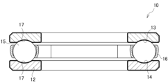
- FIG. 1 is a sectional view showing a rolling bearing according to an embodiment of the present invention.
- FIG. 2 is a cross-sectional view schematically showing the damage testing device.
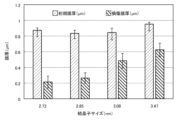
- Figure 3 shows the influence of crystallite size on damage resistance, where the vertical axis is the initial film thickness ( ⁇ m) and damaged film thickness ( ⁇ m) of the black-dyed film, and the horizontal axis is crystallite size (nm). This is a graph showing.
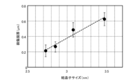
- FIG. 4 is a graph showing the effect of crystallite size on damage resistance using an approximate straight line, where the vertical axis is the damaged film thickness ( ⁇ m) of the black dyed film and the horizontal axis is the crystallite size (nm). .
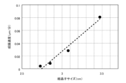
- Figure 5 shows the relationship between the film formation rate and the crystallite size of Fe 3 O 4 , where the vertical axis is the deposition rate of the black dyed film ( ⁇ m/min) and the horizontal axis is the crystallite size (nm). This is a graph showing an approximate straight line.
- Figure 6 shows the film thickness versus damage resistance, where the vertical axis is the initial film thickness ( ⁇ m) and damaged film thickness ( ⁇ m) of the black dyed film, and the horizontal axis is the initial film thickness ( ⁇ m) of the black dyed film.
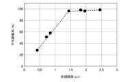
- FIG. 7 is a graph showing the influence of initial film thickness on damage resistance, where the vertical axis is the average damage rate (%) and the horizontal axis is the initial film thickness ( ⁇ m).
- FIG. 8A is a photograph substituted for a drawing showing the state of peeling when the initial thickness of the black dyed film is 0.42 ⁇ m.
- FIG. 8B is a photograph substituted for a drawing showing the state of peeling when the initial thickness of the black dyed film is 0.84 ⁇ m.
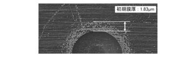
- FIG. 8C is a photograph substituted for a drawing showing the state of peeling when the initial thickness of the black dyed film is 1.83 ⁇ m.
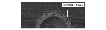
- FIG. 8D is a photograph substituted for a drawing showing the state of peeling when the initial thickness of the black dyed film is 1.97 ⁇ m.
- FIG. 8A is a photograph substituted for a drawing showing the state of peeling when the initial thickness of the black dyed film is 0.42 ⁇ m.
- FIG. 8B is a photograph substituted for a drawing showing the state of peeling when the initial thickness of the black dyed film is 0.84 ⁇ m.
- FIG. 8C is a photograph substituted for a drawing showing the state of peeling
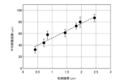
- FIG. 9 is a graph showing the influence of the initial film thickness on film destruction using an approximate straight line, where the vertical axis is the average peeling distance ( ⁇ m) and the horizontal axis is the initial film thickness ( ⁇ m) of the blackened film.
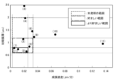
- FIG. 10 is a graph showing the relationship between the initial film thickness and crystallite size in each sample, where the vertical axis is the initial film thickness ( ⁇ m) and the horizontal axis is the crystallite size (nm).
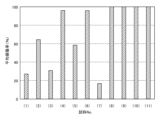
- the vertical axis represents the average damage rate (%)
- the horizontal axis represents the sample No. It is a graph which shows the average damage rate (%) in each sample when.
- FIG. 12 is a graph showing the relationship between the initial film thickness and the film formation rate for each sample, where the vertical axis is the initial film thickness ( ⁇ m) and the horizontal axis is the film formation rate ( ⁇ m/min).
- FIG. 1 is a sectional view showing a rolling bearing according to an embodiment of the present invention.
- a thrust bearing for example, will be explained as a rolling bearing.
- the thrust bearing 10 includes a first bearing ring 11 having a first raceway surface 13, a second bearing ring 12 having a second raceway surface 14, and a joint between the first raceway surface 13 and the second raceway surface 14.
- a plurality of rolling elements 15 are rotatably held between the raceway surface 14 and the raceway surface 14.
- a cage 16 that holds a plurality of rolling elements 15 at predetermined intervals is arranged between the first raceway surface 13 and the second raceway surface 14.
- an oxide film 17 containing Fe 3 O 4 is formed on the first raceway surface 13 and the second raceway surface 14, respectively. Furthermore, the thickness of the oxide film 17 and the crystallite size of Fe 3 O 4 constituting the oxide film 17 are appropriately controlled.
- the oxide film 17 is formed by a processing method generally referred to as "black dyeing", so below, the process for forming the oxide film 17 will be referred to as “black dyeing”, and the oxide film 17 will be referred to as “black dyeing”. Sometimes called a membrane.
- crystallite size of Fe 3 O 4 refers to the crystallite size calculated from the peak attributed to the (311) plane of Fe 3 O 4 .
- the rolling bearing according to the present embodiment has Fe 3 on the surface of a predetermined region of the thrust bearing 10 (specifically, at least one of the first raceway surface 13, the second raceway surface 14, and the rolling elements 15).
- An oxide film 17 containing O 4 must be formed. Thereby, generation of hydrogen from the first raceway surface 13, second raceway surface 14, and rolling elements 15 that constitute the thrust bearing 10 can be suppressed, and the occurrence of hydrogen embrittlement can be suppressed.
- the thickness of the oxide film 17 and the crystallite size of Fe 3 O 4 constituting the oxide film 17 are appropriately controlled, the durability of the oxide film 17 can be improved, and the first orbital surface 13 , the durability of the second raceway surface 14 and the rolling elements 15 can be improved.
- the first raceway ring 11 and the second raceway raceway 12, on which the black dyed film is to be formed are immersed in a treatment solution containing sodium hydroxide (NaOH) as a main component and containing Fe 3 O 4 .
- a black dyed film was formed.
- the same treatment solution was used and various crystallite sizes were set by immersion treatment under various treatment conditions.
- a damage test was performed on the black dyed film using a damage testing device, and the film thickness before the test (initial film thickness) and the film thickness after the test were measured, and the damaged film thickness was calculated from the difference.
- FIG. 2 is a cross-sectional view schematically showing the damage testing device.
- the damage testing device 20 has a container-shaped support base 21 with an open upper end, a rotating shaft 22 for rotating the thrust bearing 10, and a rotating disk 24 fixed to the rotating shaft 22. Furthermore, lubricating oil 23 is injected into the inside of the support base 21 .
- the thrust bearing 10 is arranged between the inner bottom surface of the support stand 21 and the rotary disk 24, the second bearing ring 12 of the thrust bearing 10 is fixed to the inner bottom surface of the support stand 21, and the first The bearing ring 11 is fixed to the rotary disk 24. Thereafter, the thrust bearing 10 is rotated at a predetermined rotational speed while applying pressure to the thrust bearing 10 via the rotary shaft 22 via the rotary disk 24, and then the thickness of the blackened film after the test is measured.
- Figure 3 shows the influence of crystallite size on damage resistance, where the vertical axis is the initial film thickness ( ⁇ m) and damaged film thickness ( ⁇ m) of the black-dyed film, and the horizontal axis is crystallite size (nm).
- FIG. 4 is a graph showing the effect of crystallite size on damage resistance using an approximate straight line, where the vertical axis is the damaged thickness of the black dyed film ( ⁇ m) and the horizontal axis is the crystallite size (nm). It is.
- the initial film thickness is 0.83 ⁇ m to 0.96 ⁇ m
- the crystallite sizes are 2.73 nm, 2.85 nm, 3.08 nm, and 3.47 nm.
- Figure 5 shows the relationship between the film formation rate and the crystallite size of Fe 3 O 4 , where the vertical axis is the deposition rate of the black dyed film ( ⁇ m/min) and the horizontal axis is the crystallite size (nm).
- This is a graph showing an approximate straight line.
- the crystallite size is calculated using the Scherrer equation based on the peak attributed to the (311) plane of Fe 3 O 4 measured by X-ray diffraction using cobalt (Co) as a radiation source. It is calculated using As shown in FIG. 5, it was confirmed that there is a proportional relationship between the crystallite size of Fe 3 O 4 during the black dyeing process and the film formation rate.
- Experiments 1 and 2 mainly investigated factors that affect "coating wear.”
- Experiment 3 shown below mainly investigated factors that affect "film destruction.”
- Example 3 Effect of black dye film thickness on damage resistance
- the crystallite size is kept constant by using the same treatment solution and treatment conditions and keeping the film formation rate constant, and by varying the treatment time, the film thickness can be changed and damage resistance can be improved.
- Figure 6 shows the film thickness versus damage resistance, where the vertical axis is the initial film thickness ( ⁇ m) and damaged film thickness ( ⁇ m) of the black dyed film, and the horizontal axis is the initial film thickness ( ⁇ m) of the black dyed film.
- FIG. 7 is a graph showing the influence of initial film thickness on damage resistance, where the vertical axis is the average damage rate (%) and the horizontal axis is the initial film thickness ( ⁇ m).
- the same treatment liquid was used during the black dyeing process and the film formation rate was kept constant, so the film quality, that is, the crystallite size of Fe 3 O 4 was almost the same.
- the average damage rate is a value calculated by [average damaged film thickness at multiple locations/initial film thickness]. As shown in FIGS. 6 and 7, it can be seen that when the crystallite size of Fe 3 O 4 is made almost the same, the thinner the initial thickness of the black dyed film is, the better the damage resistance is.
- FIG. 8A to 8D are photographs substituted for drawings showing the state of peeling at each initial thickness of the black dyed film.
- the initial film thickness is 0.42 ⁇ m
- the initial film thickness is 0.84 ⁇ m
- the initial film thickness is 1.83 ⁇ m
- the initial film thickness is 1. It is 97 ⁇ m.
- An example of the peeling distance is indicated by an arrow in the figure.
- FIG. 9 is a graph showing the influence of initial film thickness on film failure using an approximate straight line, where the vertical axis is the average peeling distance ( ⁇ m) and the horizontal axis is the initial film thickness of the black dyed film ( ⁇ m). be.
- the initial film thickness of the black dyed film and the average peeling distance are in a proportional relationship.
- the black dyed film is a film obtained by oxidizing Fe to form Fe 3 O 4 , and volumetric expansion occurs during the formation of Fe 3 O 4 . Therefore, the black dyed film has residual stress, and the thicker the black dyed film is, the larger the volume expansion becomes, and the residual stress increases.
- the peeling distances shown in FIGS. 8A to 8D and FIG. 9 are thought to be due to the residual stress of the blackened film, and it was shown that the thinner the initial film thickness, the better the film breakage resistance.
- the thickness of the black dyed film particularly affects the resistance to film destruction. If the film thickness is less than 0.6 ⁇ m, the black dyed film will become too thin, its lifespan against damage will be shortened, and the effect of suppressing the hydrogen generation reaction will be reduced. Therefore, the thickness of the black dyed film is preferably 0.6 ⁇ m or more. On the other hand, if the film thickness exceeds 2.0 ⁇ m, the black dyed film is likely to break down, resulting in decreased durability. Therefore, the thickness of the black dyed film is 2.0 ⁇ m or less, preferably 1.5 ⁇ m or less, more preferably 1.2 ⁇ m or less, and even more preferably 0.8 ⁇ m or less.
- Crystal size of Fe 3 O 4 The crystallite size of Fe 3 O 4 particularly affects the coating abrasion resistance.
- the crystallite size of Fe 3 O 4 is greatly affected by the film formation rate, so if you try to make the crystallite size of Fe 3 O 4 less than 2.5 nm, it will take too much time to form the film, which will reduce productivity. decreases. Therefore, the crystallite size of Fe 3 O 4 is 2.5 nm or more, preferably 2.7 nm or more.
- the crystallite size of Fe 3 O 4 exceeds 3.2 nm, the desired damage resistance of the black dyed film cannot be obtained. Therefore, the crystallite size of Fe 3 O 4 is 3.2 nm or less, preferably 3.0 nm or less, and more preferably 2.9 nm or less.
- the thrust bearing 10 is used as a rolling bearing on which a black coating (oxide film 17) is formed
- the present invention is not limited to the thrust bearing 10, and can also be applied to, for example, a radial bearing. be able to.
- the region where the oxide film 17 is formed is not limited to the raceway surface (first raceway surface 13, second raceway surface 14) side as explained in the above embodiment, but may also be on the surface side of the rolling element 15. It may also be formed on both sides.
- the oxide film 17 may be formed on both the first raceway surface 13, the second raceway surface 14, and the surface of the rolling element 15. preferable.
- the rolling elements 15 may be balls or rollers.
- the number of times of blackening treatment may be one or more times.
- this invention is not limited to SUJ2 steel material, It is applicable also to steel material which can be black-tinted.
- the method for manufacturing a rolling bearing according to the present embodiment is a method for manufacturing the above-mentioned rolling bearing, in which at least one of the first raceway surface 13, the second raceway surface 14, and the surface of the rolling element 15 contains Fe 3 O 4 .
- the method includes a step of forming a black dyed film (oxide film 17) containing . Conditions in the method for manufacturing a rolling bearing according to this embodiment will be described below.
- the deposition rate of the black dyed film greatly affects the crystallite size of Fe 3 O 4 .
- the deposition rate of the oxide film is 0.034 ⁇ m/min or less, preferably 0.026 ⁇ m/min or less.
- the thrust bearing 10 shown in FIG. 1 was manufactured using SUJ2 steel specified in JIS G 4805:2019, and the thrust races constituting the first raceway surface 13 and the second raceway surface 14 were subjected to various processing conditions. A black dyeing process was performed to form an oxide film 17 containing Fe 3 O 4 having various crystallite sizes. Note that the crystallite size of Fe 3 O 4 was adjusted as appropriate by controlling the deposition rate of the oxide film 17.
- the thrust bearing 10 has an inner diameter of 25 mm, an outer diameter of 52 mm, and a width of 18 mm, and uses six rolling elements 15 each having a diameter of 3/8 inch.
- treatment liquid A, treatment liquid B, and treatment liquid C in Table 1 below are treatment liquids that have NaOH as a main component and have different compositions, and are generally used as treatment liquids for blackening treatment. It is.
- sample No. In (2) in accordance with DIN 50938:2018-01, black dyeing treatment was performed for 30 minutes each time, and two consecutive treatments were performed at different processing speeds. The other samples were subjected to one black dyeing process. Crystallite size was measured in the same manner as in Experiment 1.
- the thrust trace of each sample was cut, and the remaining black dyed film (residual film thickness) was measured at four locations using a scanning electron microscope (SEM).
- the thickness of the blackened film in the area not touched by the rolling element is taken as the initial film thickness ( ⁇ m), and the residual film thickness at each point is subtracted from the initial film thickness and averaged to give the average damaged film thickness ( ⁇ m).
- the average damaged film thickness was divided by the initial film thickness and multiplied by 100 to obtain the average damage rate (%).
- the initial film thickness and the results of the damage test are also shown in Table 1 below.
- FIG. 10 is a graph showing the relationship between the initial film thickness and crystallite size for each sample, where the vertical axis is the initial film thickness ( ⁇ m) and the horizontal axis is the crystallite size (nm).
- the vertical axis represents the average damage rate (%)
- the horizontal axis represents the sample No. It is a graph which shows the average damage rate (%) in each sample when.
- FIG. 12 is a graph showing the relationship between the initial film thickness and film formation rate for each sample, where the vertical axis is the initial film thickness ( ⁇ m) and the horizontal axis is the film formation rate ( ⁇ m/min). be.
- sample No. 8 since the thickness of the black dyed film (initial film thickness) exceeds the upper limit of the range of the present invention, the average damage rate is 100%, and a black dyed film with poor durability is formed. Shown. In addition, sample No. In cases (9) to (11), since the crystallite size of the black dyed film exceeds the upper limit of the range of the present invention, the average damage rate is 100%, resulting in the formation of a black dyed film with poor durability. Shown.
- sample No. Regarding (1) to (7) the film formation rate was appropriately controlled and a blackened film having a desired initial film thickness of 0.6 ⁇ m or more and 2.0 ⁇ m or less was formed.
- the crystallite size of Fe 3 O 4 was 2.5 nm or more and 3.2 nm or less. Therefore, sample no. (1) to (7) are capable of obtaining a black dyed film that remains even after a severe damage test and has good durability regardless of the treatment solution and the number of times of treatment; , the film formation did not take too much time and the productivity was good.
- the initial film thickness is 1.2 ⁇ m or less, which is the more preferable upper limit of the present invention, and the crystallite size is 2.5 nm or more and 3.2 nm or less. Therefore, the average damage rate was 65% or less in all cases, and it was possible to obtain a black dyed film with excellent durability.
- sample No. Sample No. (7) has the smallest crystallite size, so the time required for film formation is longer than sample No. Although it increased compared to (1) to (6), the average damage rate was the lowest and the durability was excellent.
- the film formation rate is controlled to 0.003 ⁇ m/min to 0.034 ⁇ m/min, and the initial film thickness is within the more preferable range of the present invention.
- the black dyed film was formed to have a thickness of .2 ⁇ m or less, the average damage rate was 65% or less in all cases, and it was possible to obtain a black dyed film with excellent durability.
- the film formation rate was set to 0.026 ⁇ m/min or less, which is a preferable range, and the blackened film was formed so that the initial film thickness was 0.8 ⁇ m or less, which is a particularly preferable range, the average damage rate was 40 ⁇ m/min. % or less, confirming further improvement in durability.
Landscapes
- Engineering & Computer Science (AREA)
- General Engineering & Computer Science (AREA)
- Mechanical Engineering (AREA)
- Chemical & Material Sciences (AREA)
- Chemical Kinetics & Catalysis (AREA)
- Materials Engineering (AREA)
- Metallurgy (AREA)
- Organic Chemistry (AREA)
- Manufacturing & Machinery (AREA)
- Rolling Contact Bearings (AREA)
Abstract
Description
そこで、水素の侵入による水素脆性の発生を防止するために、表面に酸化膜を有する転がり軸受が提案されている。例えば、特許文献1には、転がり軸受を構成する転動部品の表面に、水素発生反応が生じることを抑制する酸化膜を備えた転がり軸受が開示されている。
上記特許文献2には、転がり軸受に働く径方向の負荷が無負荷又は軽負荷である状態で発生しやすいクリープを抑制し、ハウジングの内周面が摩耗することを抑制することが可能となることが記載されている。
すなわち、Fe3O4の結晶子サイズが小さいほど緻密な膜となり、被膜摩耗を低減することができ、酸化膜の膜厚が薄いほど、被膜破壊を低減することができる。本発明はこれらの知見に基づいてなされたものである。
前記第1軌道面及び前記第2軌道面、並びに前記転動体の表面における少なくとも一方に、Fe3O4を含有する酸化膜を有し、
前記酸化膜の膜厚は0.6μm以上2.0μm以下であり、
前記Fe3O4の(311)面に帰属されるピークより算出される結晶子サイズは、2.5nm以上3.2nm未満であることを特徴とする転がり軸受。
[3] [1]又は[2]に記載の転がり軸受を製造する製造方法において、
前記第1軌道面及び前記第2軌道面、並びに前記転動体の表面における少なくとも一方に、Fe3O4を含有する酸化膜を形成する工程を有し、
前記酸化膜の成膜速度を0.003μm/分以上0.034μm/分以下とすることを特徴とする、転がり軸受の製造方法。
図1は、本発明の実施形態に係る転がり軸受を示す断面図である。本実施形態においては、転がり軸受として、例えばスラスト軸受について説明する。
図1に示すように、スラスト軸受10は、第1軌道面13を有する第1軌道輪11と、第2軌道面14を有する第2軌道輪12と、これらの第1軌道面13と第2軌道面14との間で転動自在に保持された複数の転動体15と、を備える。なお、第1軌道面13と第2軌道面14との間には、複数の転動体15を所定の間隔で保持する保持器16が配置されている。
酸化膜の耐久性を向上させるためには、上述した「被膜摩耗」と「被膜破壊」の両方を抑制することが重要である。また、「被膜摩耗」に影響を及ぼすのは、Fe3O4の結晶子サイズである。さらに、結晶子サイズは、成膜速度に影響され、黒染め処理の処理温度、処理液及び黒染め処理する鋼材の種類に依存する。一方、「被膜破壊」に影響を及ぼすのは、残留応力であり、これは黒染め膜の膜厚に影響される。さらに、膜厚は、黒染め処理の処理時間及び成膜速度に影響される。
なお、耐久性の判断において、「耐摩耗性」及び「耐破壊性」を完全に区別して測定することが困難であるため、両者をまとめて「耐損傷性」という。
以下、Fe3O4の結晶子サイズと耐損傷性との関係を調査するために行った、実験1及び実験2の結果と考察について述べる。
黒染め処理による酸化膜の膜厚をほぼ一定として、成膜速度を種々に変化させることにより、結晶子サイズを変化させ、黒染め膜の耐損傷性に与える影響を調査した。結晶子サイズは、黒染め処理による酸化膜を、コバルト(Co)を線源としたX線回折法(XRD:X-ray Diffraction)により測定し、Fe3O4の(311)面に帰属されるピークに基づき、Scherrer式を利用して算出した。
まず、JIS G 4805:2019に規定されるSUJ2鋼材からなるスラスト軸受10の第1軌道面13及び第2軌道面14の表面に、黒染め膜を形成した。具体的には、黒染め膜の形成対象である第1軌道輪11及び第2軌道輪12を、水酸化ナトリウム(NaOH)を主成分とする処理液に浸漬し、Fe3O4を含有する黒染め膜を形成した。
なお、実験1では同じ処理液を使用し、種々の処理条件で浸漬処理することにより、種々の結晶子サイズを設定した。
その後、損傷試験装置により黒染め膜の損傷試験を行い、試験前の膜厚(初期膜厚)と試験後の膜厚を測定することにより、その差から損傷膜厚を算出した。
損傷試験時においては、支持台21の内底面と回転盤24との間にスラスト軸受10を配置し、スラスト軸受10の第2軌道輪12を支持台21の内底面に固定するとともに、第1軌道輪11を回転盤24に固定する。その後、回転盤24を介して、回転軸22によりスラスト軸受10に圧力を印加しつつ、所定の回転速度で回転させた後、試験後の黒染め膜の膜厚を測定する。
また、図4は、縦軸を黒染め膜の損傷膜厚(μm)とし、横軸を結晶子サイズ(nm)とした場合の、耐損傷性に対する結晶子サイズの影響を近似直線で示すグラフである。
なお、初期膜厚は0.83μm~0.96μmであり、結晶子サイズは、2.73nm、2.85nm、3.08nm、3.47nmの4点である。
また、図4に示すように、結晶子サイズと損傷膜厚は比例関係となった。これらの結果より、同一の膜厚で比較した場合には、結晶子サイズが小さい方が耐損傷性に優れることがわかる。
次に、上記実験1において作製したスラスト軸受のうち、結晶子サイズを2.73nm、2.85nm、3.08nm、3.47nmとしたスラスト軸受について、成膜速度の影響を調査した。成膜速度は、単位時間あたりに生成する酸化膜の膜厚(μm/分)である。
図5に示すように、黒染め処理時のFe3O4の結晶子サイズと、成膜速度とは比例関係にあることが確認された。また、上述のとおり、結晶子サイズと成膜速度とは比例関係にあり、かつ、結晶子サイズと損傷膜厚とが比例関係にあることから、成膜速度が低いほど結晶子サイズが小さくなり、耐損傷性に優れることが示された。
続いて、黒染め膜の膜厚と耐損傷性との関係を調査するために行った、実験3及び実験4の結果と考察について述べる。
黒染め処理時に、互いに同じ処理液と処理条件を使用し、成膜速度を一定とすることで結晶子サイズを一定とし、処理時間を種々に変化させることにより、膜厚を変化させ、耐損傷性に与える影響を調査した。
まず、上記実験1と同様の方法で、スラスト軸受10の第1軌道面13及び第2軌道面14の表面に、黒染め膜を形成した。なお、結晶子サイズは、3±0.04nmとし、得られた種々の膜厚を有するスラスト軸受10に対して、実験1と同様の損傷試験を実施した。
また、図7は、縦軸を平均損傷率(%)とし、横軸を初期膜厚(μm)とした場合の、耐損傷性に対する初期膜厚の影響を示すグラフである。
なお、実験3では、黒染め処理時に互いに同じ処理液を使用するとともに、成膜速度を一定としているため、膜質、すなわちFe3O4の結晶子サイズはほぼ同一となっている。また、平均損傷率とは、[複数個所の平均損傷膜厚/初期膜厚]によって算出される値とする。
図6及び図7に示すように、Fe3O4の結晶子サイズをほぼ同一とした場合に、黒染め膜の初期膜厚が薄い方が耐損傷性に優れることがわかる。
黒染め膜の膜厚を種々に変化させ、耐損傷性のうち、特に被膜破壊に対する影響を調査した。具体的には、まず、上記実験3と同様の方法で、種々の膜厚の黒染め膜を有するスラスト軸受10を作製した。次に、ロックウェル硬さ試験のスケールC(HRC)に規定される荷重及び圧子を使用して、黒染め膜の表面に5つの圧痕を形成した。その後、圧痕の周辺の黒染め膜を観察するとともに、各圧痕の最外周縁部から黒染め膜の剥離領域までの距離(剥離距離)を測定した。なお、剥離距離は、5つの圧痕すべてにおいて、各圧痕につき4箇所で測定し、平均を算出した。
また、図9は、縦軸を平均剥離距離(μm)とし、横軸を黒染め膜の初期膜厚(μm)とした場合の、被膜破壊に対する初期膜厚の影響を近似直線で示すグラフである。
黒染め膜の膜厚は、特に耐被膜破壊性に影響を及ぼす。膜厚が0.6μm未満であると、黒染め膜が薄くなりすぎて、損傷に対する寿命が短くなり、水素発生反応を抑制する効果が小さくなってしまう。したがって、黒染め膜の膜厚は0.6μm以上であることが好ましい。
一方、膜厚が2.0μmを超えると、黒染め膜の被膜破壊が発生しやすくなり、耐久性が低下する。したがって、黒染め膜の膜厚は2.0μm以下とし、1.5μm以下であることが好ましく、1.2μm以下であることがより好ましく、0.8μm以下であることが更に好ましい。
Fe3O4の結晶子サイズは、特に耐被膜摩耗性に影響を及ぼす。Fe3O4の結晶子サイズは、成膜速度による影響が大きいため、Fe3O4の結晶子サイズを2.5nm未満としようとすると、成膜のための時間がかかりすぎて、生産性が低下する。したがって、Fe3O4の結晶子サイズは2.5nm以上とし、2.7nm以上であることが好ましい。
一方、Fe3O4の結晶子サイズが3.2nmを超えると、黒染め膜の所望の耐損傷性を得ることができない。したがって、Fe3O4の結晶子サイズは3.2nm以下とし、3.0nm以下であることが好ましく、2.9nm以下であることがより好ましい。
また、酸化膜17を形成する領域は、上記実施形態で説明したような軌道面(第1軌道面13,第2軌道面14)側に限定されず、転動体15の表面側であってもよく、またその両方に形成してもよい。ただし、水素脆性破壊の発生をより効果的に抑制するためには、酸化膜17は、第1軌道面13及び第2軌道面14、並びに転動体15の表面の両方に形成されていることが好ましい。さらに、転動体15は玉であっても、ころであってもよい。さらに、黒染め処理における処理回数は、1回のみであっても、複数回としてもよい。
なお、上記実施形態では、SUJ2鋼材を用いた例を示したが、本発明はSUJ2鋼材に限定されず、黒染め処理が可能な鋼材にも適用することができる。
本実施形態に係る転がり軸受の製造方法は、上記転がり軸受を製造する方法であり、上記第1軌道面13及び第2軌道面14、並びに転動体15の表面における少なくとも一方に、Fe3O4を含有する黒染め膜(酸化膜17)を形成する工程を有する。本実施形態に係る転がり軸受の製造方法における条件について、以下に説明する。
上述のとおり、黒染め膜の成膜速度は、Fe3O4の結晶子サイズに大きく影響を与える。Fe3O4の結晶子サイズは小さい方が耐損傷性に優れるが、成膜速度が0.003μm/分未満であると、生産性が低下する。したがって、黒染め膜の成膜速度は、0.003μm/分以上とする。
一方、黒染め膜の成膜速度が0.034μm/分を超えると、Fe3O4の結晶子サイズが3.2nmを超えることになり、所望の耐損傷性を得ることができない。したがって、酸化膜の成膜速度は、0.034μm/分以下とし、0.026μm/分以下とすることが好ましい。
なお、Fe3O4の結晶子サイズは、酸化膜17の成膜速度を制御することにより、適宜調整した。また、スラスト軸受10のサイズは、内径が25mm、外径が52mm、幅が18mmであり、直径が3/8インチの転動体15を6個使用するものとした。
結晶子サイズは、実験1と同様の方法で測定した。
損傷試験の具体的な条件を以下に示す。なお、以下に示す「応力サイクル数」とは、転動体が軌道輪における所定の位置を通過した回数を表す。
潤滑油の粘度(ISO粘度グレード番号):VG 68
回転速度:1000(rpm)
応力サイクル数:2.16×10⁷(回)
11 第1軌道輪
12 第2軌道輪
13 第1軌道面
14 第2軌道面
15 転動体
16 保持器
17 Fe3O4を含有する酸化膜
20 損傷試験装置
21 支持台
22 回転軸
23 潤滑油
24 回転盤
Claims (3)
- 第1軌道面を有する第1軌道輪と、第2軌道面を有する第2軌道輪と、前記第1軌道面と前記第2軌道面との間で転動自在に保持される複数の転動体と、を備える転がり軸受において、
前記第1軌道面及び前記第2軌道面、並びに前記転動体の表面における少なくとも一方に、Fe3O4を含有する酸化膜を有し、
前記酸化膜の膜厚は0.6μm以上2.0μm以下であり、
前記Fe3O4の(311)面に帰属されるピークより算出される結晶子サイズは2.5nm以上3.2nm以下であることを特徴とする転がり軸受。 - 前記酸化膜は、前記第1軌道面及び前記第2軌道面の表面、並びに前記転動体の表面に形成されていることを特徴とする、請求項1に記載の転がり軸受。
- 請求項1又は2に記載の転がり軸受を製造する製造方法において、
前記第1軌道面及び前記第2軌道面、並びに前記転動体の表面における少なくとも一方に、Fe3O4を含有する酸化膜を形成する工程を有し、
前記酸化膜の成膜速度を0.003μm/分以上0.034μm/分以下とすることを特徴とする、転がり軸受の製造方法。
Priority Applications (4)
| Application Number | Priority Date | Filing Date | Title |
|---|---|---|---|
| CN202280098095.8A CN119546865A (zh) | 2022-07-11 | 2022-08-29 | 滚动轴承及其制造方法 |
| JP2024533497A JP7740557B2 (ja) | 2022-07-11 | 2022-08-29 | 転がり軸受及びその製造方法 |
| EP22951213.2A EP4556733A4 (en) | 2022-07-11 | 2022-08-29 | BEARING AND ITS PRODUCTION PROCESS |
| US18/993,235 US20260029022A1 (en) | 2022-07-11 | 2022-08-29 | Rolling bearing and method for producing same |
Applications Claiming Priority (2)
| Application Number | Priority Date | Filing Date | Title |
|---|---|---|---|
| JP2022111257 | 2022-07-11 | ||
| JP2022-111257 | 2022-07-11 |
Publications (1)
| Publication Number | Publication Date |
|---|---|
| WO2024014007A1 true WO2024014007A1 (ja) | 2024-01-18 |
Family
ID=89536285
Family Applications (1)
| Application Number | Title | Priority Date | Filing Date |
|---|---|---|---|
| PCT/JP2022/032467 Ceased WO2024014007A1 (ja) | 2022-07-11 | 2022-08-29 | 転がり軸受及びその製造方法 |
Country Status (5)
| Country | Link |
|---|---|
| US (1) | US20260029022A1 (ja) |
| EP (1) | EP4556733A4 (ja) |
| JP (1) | JP7740557B2 (ja) |
| CN (1) | CN119546865A (ja) |
| WO (1) | WO2024014007A1 (ja) |
Citations (5)
| Publication number | Priority date | Publication date | Assignee | Title |
|---|---|---|---|---|
| WO1990008264A1 (fr) * | 1989-01-14 | 1990-07-26 | Ntn Corporation | Palier graisse |
| WO2018101246A1 (ja) * | 2016-11-29 | 2018-06-07 | パナソニック アプライアンシズ リフリジレーション デヴァイシズ シンガポール | 冷媒圧縮機およびそれを用いた冷凍・冷蔵装置 |
| JP2019039523A (ja) | 2017-08-28 | 2019-03-14 | Ntn株式会社 | 転動部品及び転がり軸受 |
| JP2019113126A (ja) | 2017-12-25 | 2019-07-11 | 株式会社ジェイテクト | 転がり軸受 |
| JP2022111257A (ja) | 2020-06-08 | 2022-07-29 | 株式会社ニューギン | 遊技機 |
Family Cites Families (1)
| Publication number | Priority date | Publication date | Assignee | Title |
|---|---|---|---|---|
| DE102017118057A1 (de) * | 2017-08-09 | 2019-02-14 | Schaeffler Technologies AG & Co. KG | Elektrische Maschine mit Wälzlager für ein Kraftfahrzeug |
-
2022
- 2022-08-29 JP JP2024533497A patent/JP7740557B2/ja active Active
- 2022-08-29 EP EP22951213.2A patent/EP4556733A4/en active Pending
- 2022-08-29 WO PCT/JP2022/032467 patent/WO2024014007A1/ja not_active Ceased
- 2022-08-29 US US18/993,235 patent/US20260029022A1/en active Pending
- 2022-08-29 CN CN202280098095.8A patent/CN119546865A/zh active Pending
Patent Citations (5)
| Publication number | Priority date | Publication date | Assignee | Title |
|---|---|---|---|---|
| WO1990008264A1 (fr) * | 1989-01-14 | 1990-07-26 | Ntn Corporation | Palier graisse |
| WO2018101246A1 (ja) * | 2016-11-29 | 2018-06-07 | パナソニック アプライアンシズ リフリジレーション デヴァイシズ シンガポール | 冷媒圧縮機およびそれを用いた冷凍・冷蔵装置 |
| JP2019039523A (ja) | 2017-08-28 | 2019-03-14 | Ntn株式会社 | 転動部品及び転がり軸受 |
| JP2019113126A (ja) | 2017-12-25 | 2019-07-11 | 株式会社ジェイテクト | 転がり軸受 |
| JP2022111257A (ja) | 2020-06-08 | 2022-07-29 | 株式会社ニューギン | 遊技機 |
Non-Patent Citations (1)
| Title |
|---|
| See also references of EP4556733A4 |
Also Published As
| Publication number | Publication date |
|---|---|
| CN119546865A (zh) | 2025-02-28 |
| JPWO2024014007A1 (ja) | 2024-01-18 |
| US20260029022A1 (en) | 2026-01-29 |
| EP4556733A1 (en) | 2025-05-21 |
| JP7740557B2 (ja) | 2025-09-17 |
| EP4556733A4 (en) | 2026-07-15 |
Similar Documents
| Publication | Publication Date | Title |
|---|---|---|
| EP1870609B1 (en) | Rolling sliding member and rolling apparatus | |
| JPH0689783B2 (ja) | グリース封入軸受 | |
| CN103429917A (zh) | 滚子轴承 | |
| JP2014029046A (ja) | リング式紡機のリング/トラベラ系 | |
| GB2354559A (en) | Rolling bearing | |
| JP4487340B2 (ja) | 転がり軸受用保持器の製造方法 | |
| JP6833330B2 (ja) | 転動装置および転がり軸受 | |
| JP7740557B2 (ja) | 転がり軸受及びその製造方法 | |
| CN112739922B (zh) | 滚动轴承以及风力发电用主轴支承装置 | |
| JP5831131B2 (ja) | ころ軸受およびその製造方法 | |
| Wang et al. | The improved mechanical and tribological properties of CrN coatings sealed via electrochemical polarization treatment | |
| JP2003148485A (ja) | 転がり軸受 | |
| JP4487530B2 (ja) | 転がり軸受用保持器及びその製造方法 | |
| JP5620860B2 (ja) | 転がり軸受 | |
| JP2005195150A (ja) | 転動装置 | |
| JP2015203175A (ja) | リング式紡機のリング/トラベラ系 | |
| JP2020033622A (ja) | 摺動部材 | |
| WO2017126323A1 (ja) | 転がり軸受、転動装置および転動装置の製造方法 | |
| US11028880B2 (en) | Rolling bearing, rolling device, and method of manufacturing rolling device | |
| Koike et al. | Wear evaluation of resin composite carbon graphite bearings for canned motor pump in dry environments | |
| WO2020067334A1 (ja) | 転がり軸受、および風力発電用主軸支持装置 | |
| JP5866801B2 (ja) | ころ軸受 | |
| JP4427224B2 (ja) | 転がり軸受 | |
| JP7857992B2 (ja) | 転がり軸受及び転がり軸受用転動体 | |
| JP2003222136A (ja) | 転動要素 |
Legal Events
| Date | Code | Title | Description |
|---|---|---|---|
| 121 | Ep: the epo has been informed by wipo that ep was designated in this application |
Ref document number: 22951213 Country of ref document: EP Kind code of ref document: A1 |
|
| WWE | Wipo information: entry into national phase |
Ref document number: 2024533497 Country of ref document: JP |
|
| WWE | Wipo information: entry into national phase |
Ref document number: 202280098095.8 Country of ref document: CN Ref document number: 18993235 Country of ref document: US |
|
| WWE | Wipo information: entry into national phase |
Ref document number: 2022951213 Country of ref document: EP |
|
| NENP | Non-entry into the national phase |
Ref country code: DE |
|
| ENP | Entry into the national phase |
Ref document number: 2022951213 Country of ref document: EP Effective date: 20250211 |
|
| WWP | Wipo information: published in national office |
Ref document number: 202280098095.8 Country of ref document: CN |
|
| WWP | Wipo information: published in national office |
Ref document number: 2022951213 Country of ref document: EP |
|
| WWP | Wipo information: published in national office |
Ref document number: 18993235 Country of ref document: US |