WO2024014103A1 - マルチコア光ファイバの光学特性の測定方法及び測定装置 - Google Patents
マルチコア光ファイバの光学特性の測定方法及び測定装置 Download PDFInfo
- Publication number
- WO2024014103A1 WO2024014103A1 PCT/JP2023/017969 JP2023017969W WO2024014103A1 WO 2024014103 A1 WO2024014103 A1 WO 2024014103A1 JP 2023017969 W JP2023017969 W JP 2023017969W WO 2024014103 A1 WO2024014103 A1 WO 2024014103A1
- Authority
- WO
- WIPO (PCT)
- Prior art keywords
- optical fiber
- end surface
- face
- core
- core optical
- Prior art date
- Legal status (The legal status is an assumption and is not a legal conclusion. Google has not performed a legal analysis and makes no representation as to the accuracy of the status listed.)
- Ceased
Links
Images





Classifications
-
- G—PHYSICS
- G01—MEASURING; TESTING
- G01M—TESTING STATIC OR DYNAMIC BALANCE OF MACHINES OR STRUCTURES; TESTING OF STRUCTURES OR APPARATUS, NOT OTHERWISE PROVIDED FOR
- G01M11/00—Testing of optical apparatus; Testing structures by optical methods not otherwise provided for
- G01M11/30—Testing of optical devices, constituted by fibre optics or optical waveguides
- G01M11/33—Testing of optical devices, constituted by fibre optics or optical waveguides with a light emitter being disposed at one fibre or waveguide end-face, and a light receiver at the other end-face
-
- G—PHYSICS
- G02—OPTICS
- G02B—OPTICAL ELEMENTS, SYSTEMS OR APPARATUS
- G02B6/00—Light guides; Structural details of arrangements comprising light guides and other optical elements, e.g. couplings
- G02B6/02—Optical fibres with cladding with or without a coating
- G02B6/02042—Multicore optical fibres
-
- G—PHYSICS
- G02—OPTICS
- G02B—OPTICAL ELEMENTS, SYSTEMS OR APPARATUS
- G02B6/00—Light guides; Structural details of arrangements comprising light guides and other optical elements, e.g. couplings
- G02B6/24—Coupling light guides
- G02B6/255—Splicing of light guides, e.g. by fusion or bonding
- G02B6/2555—Alignment or adjustment devices for aligning prior to splicing
-
- G—PHYSICS
- G02—OPTICS
- G02B—OPTICAL ELEMENTS, SYSTEMS OR APPARATUS
- G02B6/00—Light guides; Structural details of arrangements comprising light guides and other optical elements, e.g. couplings
- G02B6/24—Coupling light guides
- G02B6/36—Mechanical coupling means
- G02B6/38—Mechanical coupling means having fibre to fibre mating means
- G02B6/3807—Dismountable connectors, i.e. comprising plugs
- G02B6/3833—Details of mounting fibres in ferrules; Assembly methods; Manufacture
- G02B6/3834—Means for centering or aligning the light guide within the ferrule
- G02B6/3843—Means for centering or aligning the light guide within the ferrule with auxiliary facilities for movably aligning or adjusting the fibre within its ferrule, e.g. measuring position or eccentricity
Definitions
- the present disclosure relates to a method and apparatus for measuring optical properties of a multi-core optical fiber.
- MCF Multi-core optical fiber
- SDM space division multiplexing
- Patent Document 1 describes a method of measuring the optical characteristics of each core of an MCF using a fan-in/fine-out (FIFO) device. According to the FIFO device, the optical characteristics of each core of the MCF can be easily measured without using an alignment machine.
- FIFO fan-in/fine-out
- a method for measuring optical properties of an MCF includes connecting a first optical fiber having the same diameter as the MCF and connected to a light source to a first end surface of the MCF, and having the same diameter as the MCF. and a step of connecting a second optical fiber to be connected to the measuring device to the second end surface of the MCF, and irradiating the measurement light emitted from the light source to the first end surface via the first optical fiber, and irradiating the measurement light from the second end surface.
- the connecting step includes a step of measuring the emitted light with a measuring device via the second optical fiber, and the connecting step uses a first rotating fiber holder to hold the MCF and adjust the rotation angle of the first end face.
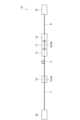
- FIG. 1 is a configuration diagram showing an apparatus for measuring optical characteristics of an MCF according to a first embodiment.
- FIG. 2 is a cross-sectional view of the MCF.
- FIG. 3 is a flowchart showing a method for measuring optical characteristics of an MCF according to the first embodiment.
- FIG. 4 is an explanatory diagram of the first alignment process using the end face observation device.
- FIG. 5 is an explanatory diagram of a first alignment process using an end face observation device according to a modification.
- FIG. 6 is an explanatory diagram of the first connecting step using the connecting portion.
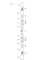
- FIG. 7 is a configuration diagram showing an apparatus for measuring optical characteristics of an MCF according to a second embodiment.
- FIG. 8 is a plan view showing the end face of the MCF and the connecting end face of the MMF.
- FIG. 9 is a configuration diagram showing an apparatus for measuring optical characteristics of an MCF according to a third embodiment.
- FIG. 10 is a plan view showing the end face of the MCF and the connecting end face of the eccentric MMF.
- FIG. 11 is a configuration diagram showing an apparatus for measuring optical characteristics of an MCF according to a fourth embodiment.
- FIG. 12 is a configuration diagram showing an apparatus for measuring optical characteristics of an MCF according to a fifth embodiment.
- An object of the present disclosure is to provide a method and apparatus for measuring the optical properties of an MCF that can be carried out easily and in a short time.
- a method for measuring optical properties of an MCF includes connecting a first optical fiber having the same diameter as the MCF and connected to a light source to a first end surface of the MCF, and a step of connecting a second optical fiber, which is connected to the measuring device, to the second end surface of the MCF; and irradiating the first end surface with measurement light emitted from the light source through the first optical fiber; The method includes a step of measuring the light emitted from the two end faces with a measuring device via a second optical fiber.
- the connecting step includes a step of holding the MCF using a first rotating fiber holder and aligning the rotation angle of the first end face, and a step of holding the first optical fiber and using a second rotating fiber holder. , aligning the rotation angle of the first connecting end surface to be connected to the first end surface of the first optical fiber; and aligning the first rotating fiber holder and the second rotating fiber holder to face each other, and aligning the first
- the method includes the steps of butting and connecting the end surface and the first connection end surface, and butting and connecting the second end surface and the second connection end surface that is connected to the second end surface of the second optical fiber. With this measurement method, the optical characteristics of the MCF can be measured easily and in a short time.
- alignment of the rotation angles of the first end face and the first connection end face may be performed based on observation of the end faces using a camera. In this case, coarse centering of the rotation can be easily performed.
- the end face observation of the first end face is performed by entering the light emitted from the first light source for end face observation into the side surface of the MCF, and the end face observation of the first connecting end face is performed. This may be performed by inputting light emitted from a second light source for end face observation into the side surface of the first optical fiber. In this case, end face observation can be performed with a simpler configuration than when using a coaxial epi-illumination light source.
- the MCF may include a glass fiber and a transparent coating resin that covers the outer peripheral surface of the glass fiber. In this case, light can be reliably entered from the side.
- the end face observation of the first end face is performed by directing the light emitted from the first coaxial epi-illumination light source for end face observation placed between the first end face and the camera to the first end face.
- the end face observation of the first connection end face is performed by inputting light emitted from a second coaxial incident light source for end face observation placed between the first connection end face and the camera into the first connection end face. It may also be done as follows. In this case, the degree of freedom in the placement of the light source increases.
- the MCF may include a glass fiber and a light-shielding coating resin that covers the outer peripheral surface of the glass fiber.
- the coaxial epi-illumination method is particularly effective.
- the camera may be an image processing compatible camera that calculates the rotation angle of the MCF and the first optical fiber. In this case, precise alignment is not required.
- the connecting step is performed after the step of butting and connecting the first end surface and the first connection end surface to the first rotating fiber holder or the second rotating fiber holder.
- the method may further include a step of precisely aligning the first end surface and the first connecting end surface using the holder. In this case, connection loss can be reduced.
- the butt-connecting step may be performed using a V-groove or capillary whose inside is filled with a refractive index matching agent. In this case, joining loss can be reduced.
- the connecting step is a step of holding the MCF and aligning the rotation angle of the second end surface using the third rotating fiber holder. and a step of holding the second optical fiber and aligning the rotation angle of the second connection end surface using a fourth rotating fiber holder, the butt connection between the second end surface and the second connection end surface is performed.
- the step may be performed with the third rotating fiber holder and the fourth rotating fiber holder facing each other with the second end surface and the second connecting end surface aligned respectively. In this case, the optical characteristics of the MCF can be measured more easily and in a shorter time.
- the second optical fiber is a single-core optical fiber having a core whose core diameter is equal to or larger than the diameter of the circumscribed circle of the plurality of cores of the MCF. You can. In this case, the second end surface and the second connection end surface can be joined without being rotationally aligned.
- the first optical fiber is a single-core optical fiber, and the distance between the central axis of the first optical fiber and the central axis of the core is , may be equal to the distance between the central axis of the MCF and the central axis of each core.
- the core of the first optical fiber and each core of the MCF can be connected by rotationally aligning the first end surface and the first connection end surface.
- An apparatus for measuring optical properties of an MCF includes a light source that enters measurement light into a first end surface of the MCF via a first optical fiber having the same diameter as the MCF, and a second end surface of the MCF.
- a first rotating fiber holder that holds the MCF and rotationally aligns the first end surface of the MCF; a second rotating fiber holder that holds the fiber and rotationally aligns a first connecting end surface connected to the MCF of the first optical fiber; a first end surface rotationally aligned by the first rotating fiber holder; It includes a first connection part that butts and connects the first connection end surface rotationally aligned by the rotating fiber holder, and a second connection part that butts and connects the second end surface of the MCF and the second optical fiber.
- a method for measuring optical properties of an MCF includes connecting a single-core optical fiber having the same diameter as the MCF and connected to a light source to the first end surface of the MCF, and A process of connecting an optical fiber having the same diameter and connected to a measuring device to the second end face of the MCF, and irradiating the first end face with the measurement light emitted from the light source via the single-core optical fiber;
- the method includes the step of measuring the light emitted from the end face using a measuring device via an optical fiber.
- the single-core optical fiber is connected to the MCF such that the core of the single-core optical fiber covers the entire core of the MCF to be measured at the first end surface.
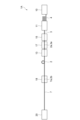
- FIG. 1 is a configuration diagram showing an apparatus for measuring optical characteristics of an MCF according to a first embodiment.
- a measuring device 1 according to the first embodiment is a device for measuring optical characteristics of an MCF 2 to be measured.
- the measuring device 1 includes a light source 10 that makes measurement light enter an end surface 2a (first end surface) of the MCF 2, and a measuring instrument 20 that measures light emitted from an end surface 2b (second end surface) of the MCF 2.
- the end surface 2a is one end surface of the MCF 2 in the longitudinal direction.
- the end surface 2b is the other end surface of the MCF 2 in the longitudinal direction.
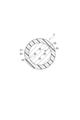
- FIG. 2 is a cross-sectional view of the MCF.
- the MCF 2 includes a glass fiber 21 and a transparent coating resin 22 that covers the outer peripheral surface of the glass fiber 21.
- Glass fiber 21 includes a plurality of cores 23, cladding 24, and markers 25.
- the plurality of cores 23 are arranged at equal intervals on concentric circles centered on the central axis of the MCF 2 in a cross section perpendicular to the central axis of the MCF 2 .
- the cladding 24 is a common cladding that surrounds the plurality of cores 23 and markers 25.
- Marker 25 has a different refractive index than cladding 24.
- the marker 25 is arranged at a position that breaks the symmetry of the arrangement of the plurality of cores 23.
- the MCF 2 is, for example, a square four-core MCF and includes four cores 23.
- the coating resin 22 is, for example, a transparent resin or a colored resin. The coating resin 22 is not provided at both ends of the glass fiber 21 in the longitudinal direction.
- the measuring device 1 includes FIFO devices 11 and 12, rotating fiber holders 13, 14, 15, and 16, and connecting portions 17 and 18.
- the FIFO device 11 includes an MCF 3 and a plurality of SMFs 4 connected to each core of the MCF 3.
- the MCF3 (first optical fiber) is an optical fiber having the same diameter as the MCF2, and has a connecting end surface 3a connected to the end surface 2a.
- MCF3 is a dummy MCF.
- the SMFs 4 corresponding to the core 23 to be measured are connected to the light source 10 one by one.
- the FIFO device 12 includes an MCF 5 and a plurality of SMFs 6 connected to each core of the MCF 5.
- the MCF5 (second optical fiber) is an optical fiber having the same diameter as the MCF2, and has a connecting end surface 5a connected to the end surface 2b. MCF5 is a dummy MCF. Among the plurality of SMFs 6 , the SMFs 6 corresponding to the cores 23 to be measured are connected to the measuring device 20 one by one.
- the rotating fiber holders 13, 14, 15, and 16 have the function of rotatably holding the optical fiber and maintaining the rotational state of the optical fiber at an arbitrary rotation angle.
- Rotating fiber holders 13 and 14 hold MCF2.
- the rotating fiber holder 13 (first rotating fiber holder) holds, for example, a portion of the MCF 2 near the end surface 2a, and rotationally aligns the end surface 2a.
- the rotating fiber holder 14 holds, for example, a portion of the MCF 2 near the end surface 2b, and rotationally aligns the end surface 2b.
- the rotating fiber holder 15 (second rotating fiber holder) holds the MCF 3 of the FIFO device 11.
- the rotating fiber holder 15 holds, for example, a portion of the MCF 3 closer to the connection end surface 3a, and rotationally aligns the connection end surface 3a (first connection end surface).
- the rotating fiber holder 16 holds the MCF 5 of the FIFO device 12.
- the rotating fiber holder 16 holds, for example, a portion of the MCF 5 closer to the connection end surface 5a (second connection end surface), and rotationally aligns the connection end surface 5a.
- Each of the connecting portions 17 and 18 is, for example, a V-groove (V-groove substrate) whose inside is filled with a refractive index matching agent.
- the connecting portion 17 butts and connects the end surface 2 a of the MCF 2 rotationally aligned by the rotating fiber holder 13 and the connecting end surface 3 a of the MCF 3 rotationally aligned by the rotating fiber holder 15 .
- the connecting portion 18 butts and connects the end surface 2b of the MCF 2 rotationally aligned by the rotating fiber holder 14 and the connecting end surface 5a of the MCF 5 rotationally aligned by the rotating fiber holder 16 (V contact).
- the refractive index matching agent is, for example, a matching oil. The refractive index matching agent reduces connection loss.
- connection part 17, 18 may be a capillary whose inside is filled with a refractive index matching agent.
- the maximum manufacturing error in the inner diameter of the capillary is set within, for example, the bare fiber diameter (that is, the diameter of the glass fiber 21) + 1 ⁇ m.
- Silica glass (SiO 2 ) or zirconium oxide (ZrO 2 ) can be used as a material for the capillary.
- the measurement light emitted from the light source 10 is incident on the end surface 2a of the MCF 2 via the SMF 4 and MCF 3 of the FIFO device 11.
- the light that passes through the MCF2 and is emitted from the end surface 2b of the MCF2 enters the measuring device 20 via the MCF5 and SMF6 of the FIFO device 12, and is measured by the measuring device 20.
- the MCF 2 when replacing the MCF 2 to be measured, the MCF 2 is removed together with the rotating fiber holders 13 and 14, for example.
- the removed MCF 2 may be transferred together with the rotating fiber holders 13 and 14 to another measuring device 1, and other optical characteristics may be measured.
- the MCF 2 newly attached to the measuring device 1 may be transferred to the measuring device 1 together with the rotating fiber holders 13 and 14, and its optical characteristics may be measured. Since the FIFO devices 11 and 12 are not moved, it is not necessary to align the connection end surfaces 3a and 5a from the second time onwards.
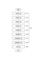
- FIG. 3 is a flowchart showing a method for measuring optical characteristics of an MCF according to the first embodiment.
- the measurement method according to the first embodiment includes a connection step S10 and a measurement step S20.
- the connection step S10 is a step in which the connection end surface 3a of the MCF3 of the FIFO device 11 is connected to the end surface 2a of the MCF2, and the connection end surface 5a of the MCF5 of the FIFO device 12 is connected to the end surface 2b of the MCF2.
- the end face 2a is irradiated with measurement light from the light source 10 via the SMF 4 and MCF 3 of the FIFO device 11, and the light emitted from the end face 2b is emitted by the measuring instrument 20 via the MCF 5 and SMF 6 of the FIFO device 12. This is the process of measuring.
- the connection process S10 includes a first alignment process S11, a second alignment process S12, a third alignment process S13, a fourth alignment process S14, a first connection process S15, a second connection process S16, and a first precision alignment. It includes a step S17 and a second precision alignment step S18.
- the first alignment step S11 is a step of holding the MCF 2 using the rotating fiber holder 13 and aligning the rotation angle of the end surface 2a.
- the second alignment step S12 is a step of holding the MCF 3 using the rotating fiber holder 15 and aligning the rotation angle of the connection end surface 3a of the MCF 3.
- the third alignment step S13 is a step of holding the MCF 2 and aligning the rotation angle of the end surface 2b using the rotating fiber holder 14.
- the fourth alignment step S14 is a step of holding the MCF 5 using the rotating fiber holder 16 and aligning the rotation angle of the connecting end surface 5a of the MCF 5.
- each alignment process S12, S13, and S14 the rotation angles of the end face 2a, the connecting end face 3a, the end face 2b, and the connecting end face 5a are aligned based on end face observation using a camera.
- the rotational angle is roughly aligned (coarse rotational alignment).
- the coarse rotational alignment although the rotational alignment of the MCF2 and the MCFs 3 and 5 is not perfect, sufficient alignment accuracy can be obtained by simply measuring the optical characteristics of each core 23 of the MCF2. If the accuracy of the coarse rotational alignment is insufficient, it is also possible to perform precise rotational alignment by adjusting the rotation of the rotating fiber holders 13, 14, 15, and 16 in a subsequent process.
- FIG. 4 is an explanatory diagram of the first alignment step using the end face observation device.
- the end surface observation device 30 shown in FIG. 4 is used to observe each end surface of the end surface 2a, the end surface 2b, and the connection end surfaces 3a and 5a in each alignment step S11, S12, S13, and S14.
- the end face observation device 30 includes a light source 31 and a camera 32.
- Each alignment step S11, S12, S13, and S14 will be explained below. Note that each alignment step S11, S12, S13, and S14 may be performed using one end surface observation device 30, or each alignment step S11, S12, S13, and S14 may be performed using a different end surface observation device 30. You may do so.
- the end face observation device 30 further includes a rotating fiber holder 13.
- MCF2 is installed on rotating fiber holder 13.
- the light source 31 (first light source for end-face observation) is installed on the side of the MCF 2 and irradiates the side of the MCF 2 with light.
- the light source 31 causes light to enter the MCF 2 laterally through the coating resin 22.
- the camera 32 is installed at a position facing the end surface 2a.
- the camera 32 receives light that passes through the MCF 2 and is emitted from the end surface 2a. That is, the end face observation of the end face 2a is performed by using the light source 31 for end face observation and injecting light from the side surface of the MCF 2. In other words, the end face observation of the end face 2a is performed by making light emitted from the light source 31 for end face observation enter the side surface of the MCF 2.
- the end face observation device 30 further includes a rotating fiber holder 15.
- the MCF 3 is installed on the rotating fiber holder 15.
- the light source 31 (second light source for end face observation) is installed on the side of the MCF 3 and irradiates the side of the MCF 3 with light.
- the light source 31 causes light to enter the MCF 3 laterally through the coating resin.
- the camera 32 is installed at a position facing the connection end surface 3a.
- the camera 32 receives light that passes through the MCF 3 and is emitted from the connection end surface 3a. That is, the end face observation of the connection end face 3a is performed by using the light source 31 for end face observation and injecting light from the side surface of the MCF 3. In other words, the end face observation of the connection end face 3a is performed by making the light emitted from the light source 31 for end face observation enter the side surface of the MCF 3.
- the end face observation device 30 further includes a rotating fiber holder 14.
- MCF 2 is installed on rotating fiber holder 14 .
- the light source 31 is installed on the side of the MCF 2 and irradiates the side of the MCF 2 with light.
- the light source 31 causes light to enter the MCF 2 laterally through the coating resin 22.
- the camera 32 is installed at a position facing the end surface 2b.
- the camera 32 receives light that passes through the MCF 2 and is emitted from the end surface 2b. That is, the end face observation of the end face 2b is performed by using the light source 31 for end face observation and injecting light from the side surface of the MCF 2. In other words, the end face observation of the end face 2b is performed by making the light emitted from the light source 31 for end face observation enter the side surface of the MCF 2.
- the end face observation device 30 further includes a rotating fiber holder 16.
- the MCF 5 is installed on the rotating fiber holder 16.
- the light source 31 is installed on the side of the MCF 5 and irradiates the side of the MCF 5 with light.
- the light source 31 causes light to enter the MCF 5 laterally through the coating resin.
- the camera 32 is installed at a position facing the connection end surface 5a.
- the camera 32 receives light that passes through the MCF 5 and is emitted from the connection end surface 5a. That is, the end face observation of the connection end face 5a is performed by using the light source 31 for end face observation and injecting light from the side surface of the MCF 5.
- the camera 32 may be, for example, an image processing compatible camera that calculates the rotation angle of the end surface 2a, the end surface 2b, the connection end surface 3a, and the connection end surface 5a. In this case, since precise rotational alignment is not required in the post-process, the measurement time can be further shortened.
- the end face observation device 30 may further include a suction stage capable of vacuum suction or a V-groove in order to fix the observed end face during observation with the camera 32.
- FIG. 5 is an explanatory diagram of the first alignment process using the end face observation device according to the modification.
- the end face observation device 30A according to the modification shown in FIG. 5 further includes an optical component 33 consisting of a beam splitter or a half mirror.
- the optical component 33 is arranged on a camera observation axis that connects the center of the observation end face (that is, the end face 2a, the end face 2b, and each end face of the connecting end faces 3a and 5a) and the center of the camera 32.
- the light source 31 is arranged between the observation end face and the camera 32, and irradiates the optical component 33 with light from a direction perpendicular to the camera observation axis.
- the optical component 33 reflects the light emitted from the light source 31 and allows the light to enter the observation end face parallel to the camera observation axis.
- the camera 32 receives the light reflected by the observation end face and transmitted through the optical component 33 .
- the end face observation of the end face 2a, the end face 2b, and the connecting end faces 3a, 5a is performed using a coaxial camera for end face observation arranged between the observation end face and the camera 32.
- the light source 31 (a first coaxial epi-illumination light source and a second coaxial epi-illumination light source) is used as an epi-illumination light source, and light is incident on each observation end face in a coaxial epi-illumination method.
- the end faces 2a, 2b, and the connecting end faces 3a, 5a are observed by making the light emitted from the light source 31, which is a coaxial incident light source for end face observation, enter each observation end face.
- the coating resin 22 of the MCF 2 may have a light-shielding property.
- the coating resin of MCFs 3 and 5 may be light-shielding.
- FIG. 6 is an explanatory diagram of the first connection step using the connection part.
- the rotating fiber holder 13 and the rotating fiber holder 15 are made to face each other using the connecting portion 17, and the aligned end surfaces 2a and the connecting end surfaces 3a are butt-connected.
- the first connection step S15 further includes a step of connecting, among the plurality of SMFs 4 of the FIFO device 11, the SMF 4 corresponding to the core 23 to be measured to the light source 10.
- the second connection step S16 includes a step of butt-connecting the end surface 2b and the connection end surface 5a using the connection portion 18.
- the butt connection between the end surface 2b and the connection end surface 5a is performed with the rotating fiber holder 14 and the rotating fiber holder 16 facing each other in an aligned state. That is, the second connection step S16 is a step in which the rotating fiber holder 14 and the rotating fiber holder 16 are made to face each other, and the aligned end surfaces 2b and connection end surfaces 5a are butt-connected.
- the connecting portion 18 and the rotating fiber holders 14 and 16 constitute a fiber abutting device.
- the second connection step S16 further includes a step of connecting the SMF 6 corresponding to the core 23 to be measured, among the plurality of SMFs 6 of the FIFO device 12, to the measuring instrument 20.
- the first precision alignment step S17 is a step in which the end surface 2a and the connection end surface 3a are precisely aligned by finely adjusting the rotation of the rotating fiber holder 13 or the rotating fiber holder 15 after the first connection step S15.
- the first fine alignment step S17 is performed when the coarse rotational alignment accuracy between the end surface 2a and the connection end surface 3a is low and the coupling of light is insufficient. The state of light coupling can be confirmed by emitting measurement light from the light source 10 and measuring the light with the measuring device 20.
- the second precision alignment step S18 is a step in which the end surface 2b and the connection end surface 5a are precisely aligned by finely adjusting the rotation of the rotating fiber holder 14 or the rotating fiber holder 16 after the second connection step S16.
- the second fine alignment step S18 is performed when the coarse rotational alignment accuracy between the end surface 2b and the connection end surface 5a is low and the coupling of light is insufficient.
- the state of light coupling can be confirmed by emitting measurement light from the light source 10 and measuring the light with the measuring device 20.
- each fine alignment process S17 and S18 is essentially unnecessary or is very simple. , and it takes only a short time. Thereby, the connection between the MCF2 and the MCFs 3 and 5 can be easily performed. Therefore, the optical characteristics of each core 23 of the MCF 2 can be easily measured using the FIFO devices 11 and 12.
- the optical characteristics of all cores 23 can be measured using the FIFO devices 11 and 12 while easily changing the core 23 to be measured. Specifically, the core 23 can be changed by simply connecting the SMF 4 connected to the light source 10 and the SMF 6 connected to the measuring device 20 to the SMF 4, 6 corresponding to the next core 23 to be measured. be.
- FIG. 7 is a configuration diagram showing an apparatus for measuring optical characteristics of an MCF according to a second embodiment.
- a measuring device 1A according to the second embodiment shown in FIG. 7 will be described with a focus on differences from the measuring device 1.
- the measuring device 1A includes a multimode fiber (MMF) 7 connected to a measuring instrument 20 instead of the FIFO device 12.
- the measuring device 1A does not include the FIFO device 12 and the rotating fiber holders 14 and 16.
- the MMF7 (second optical fiber) is an optical fiber having the same diameter as the MCF2, and has a connection end surface 7a (second connection end surface) connected to the end surface 2b of the MCF2.
- MMF7 is a dummy fiber.
- the connecting portion 18 butts and connects the end surface 2b of the MCF 2 and the connecting end surface 7a of the MMF 7.
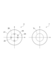
- FIG. 8 is a plan view showing the end face of the MCF and the connecting end face of the MMF.
- the circumscribed circles 26 of the plurality of outermost cores 23 are virtually shown on the end surface 2b of the MCF 2.
- the MMF 7 is a single-core optical fiber and has a large diameter core 7c that can receive light from all the cores 23 of the MCF 2.
- the core 7c has a core diameter greater than or equal to the diameter of the circumscribed circle 26. In other words, the diameter of the core 7c (core diameter) is greater than or equal to the diameter of the circumscribed circle 26. Therefore, the end surface 2b and the connecting end surface 7a can be connected without rotational alignment.
- the measurement method according to the second embodiment differs from the measurement method according to the first embodiment in that it does not include the third alignment step S13, the fourth alignment step S14, and the second fine alignment step S18. ing.
- the second connection step S16 the unaligned end surface 2b and the connection end surface 7a are butt-connected, and the end surface of the MMF 7 opposite to the connection end surface 7a is connected to the measuring device 20.
- the measurement method according to the second embodiment can be used, for example, in measurements where the optical fiber on the receiving side (measuring device 20 side) can be made into a multi-mode, such as the cutback method.
- the cutback method after cutting the MCF 2, it is necessary to reconnect the cut end surface to the connection end surface of the dummy fiber.
- the third alignment step S13 is required once more, which increases the measurement time accordingly.
- the measurement method according to the second embodiment when reconnecting the cut end surface 2b, rotational alignment of the end surface 2b is not required, and measurement can be performed only by a butting operation, so the measurement time is shortened. be done.
- FIG. 9 is a configuration diagram showing an apparatus for measuring optical characteristics of an MCF according to a third embodiment.
- a measuring device 1B according to the third embodiment shown in FIG. 9 will be described with a focus on differences from the measuring device 1.
- the measuring device 1B includes an eccentric MMF 8 connected to the light source 10 instead of the FIFO device 11, and an eccentric MMF 9 connected to the measuring instrument 20 instead of the FIFO device 12.
- the eccentric MMF 8 (first optical fiber) is an optical fiber having the same diameter as the MCF 2 and has a connection end surface 8 a (first connection end surface) connected to the end surface 2 a of the MCF 2 .
- the eccentric MMF 8 is a dummy fiber.
- the eccentric MMF 9 (second optical fiber) is an optical fiber having the same diameter as the MCF 2, and has a connection end surface 9a (second connection end surface) connected to the end surface 2b of the MCF 2.
- the eccentric MMF 9 is a dummy fiber.
- FIG. 10 is a plan view showing the end face of the MCF and the connecting end face of the eccentric MMF.
- the eccentric MMF 8 is a single-core optical fiber, and has a core 8c provided at a position eccentric from the central axis of the eccentric MMF 8.
- the distance between the central axis of the eccentric MMF 8 and the central axis of the core 8c is equal to the distance between the central axis of the MCF 2 and the central axis of each core 23.
- the core 8c can receive light from each core 23 of the MCF2.
- the core pitch is ⁇
- the distance between the central axis of eccentric MMF8 and the central axis of core 8c is d1
- the eccentric MMF 9 has the same configuration as the eccentric MMF 8.
- the measurement method according to the third embodiment is used, for example, to measure the cutoff wavelength.
- the dummy fibers connected to both ends of the fiber under test are MMF for multimode excitation.
- MCF if an MM-MCF capable of multimode waveguide is prepared as a dummy fiber, the cutoff wavelength can be measured independently for each core.
- an increase in the core diameter increases inter-core crosstalk, which adversely affects the measurement results, so the use of a FIFO device may not be suitable for measuring the cutoff wavelength.
- the measurement method according to the third embodiment does not use a FIFO device, inter-core crosstalk is suppressed.
- the measurement method according to the third embodiment when changing the core 23 to be measured, it is necessary to rotationally align the eccentric MMFs 8 and 9 and reconnect them to the end surfaces 2a and 2b. That is, the optical characteristics of each core 23 of the MCF 2 can be measured by performing all the steps of the connection step S10 and the measurement step S20 the same number of times as the number of cores 23 of the MCF 2.
- FIG. 11 is a configuration diagram showing an apparatus for measuring optical characteristics of an MCF according to a fourth embodiment.
- a measuring device 1C according to the fourth embodiment shown in FIG. 11 will be described with a focus on differences from the measuring device 1B.
- the measuring device 1C includes an MMF 7 (second optical fiber), which is also used in the measurement method according to the second embodiment, instead of the eccentric MMF 9.
- the measuring device 1C does not include rotating fiber holders 14 and 16. Similar to the measurement method according to the second embodiment, MMF7, which can receive light from all cores 23, is used as the dummy fiber on the receiving side (measuring device 20 side), so rotational alignment is not required on the receiving side. , measurement time can be shortened because measurement can be performed only by a butting operation.
- FIG. 12 is a configuration diagram showing an apparatus for measuring optical characteristics of an MCF according to a fifth embodiment.
- the measuring device 1D according to the fifth embodiment shown in FIG. 12 will be described with a focus on the differences from the measuring device 1.
- the measuring device 1D includes a FIFO device 41 used in place of the FIFO devices 11 and 12, and a FIFO device 42 used in place of the FIFO device 12.
- the FIFO device 41 includes an MM-MCF 43 (first optical fiber) including a connection end surface 43a (first connection end surface) connected to the end surface 2a, and a plurality of MMFs 44 connected to the light source 10.
- the FIFO device 42 includes an MM-MCF 45 (second optical fiber) including a connection end surface 45a (second connection end surface) connected to the end surface 2b, and a plurality of MMFs 46 connected to the measuring instrument 20.
- the measuring device 1D is used, for example, to measure a cutoff wavelength.
- the eccentric MMF 8 may be connected to the MCF 2 such that the central axis of the core 8c coincides with the central axis of the core 23 to be measured. It is not necessary to connect so as to coincide with the central axis of the target core 23.
- the eccentric MMF 8 can measure optical characteristics if it is connected to the MCF 2 so that the core 23 to be measured is included in the core 8c.
- the eccentric MMF 8 may be connected to the MCF 2 so that the core 8c covers the entire core 23 to be measured at the end surface 2a.
- the FIFO device 12 may be connected to the measuring instrument 20 as in the first embodiment, or the MMF 7 may be connected as in the second embodiment. Regardless of the combination of measurement methods, the optical characteristics of the MCF can be measured easily and in a short time.
- Rotating fiber holder (first rotating fiber holder) 14...Rotating fiber holder (third rotating fiber holder) 15... Rotating fiber holder (second rotating fiber holder) 16...Rotating fiber holder (4th rotating fiber holder) 17, 18...Connection part 20...Measuring device 21...Glass fiber 22...Coating resin 23...Core 24...Clad 25...Marker 26...Circumcircle 30, 30A...End face observation device 31...Light source (first light source for end face observation, a second light source for end face observation, a first coaxial epi-illumination light source, and a second coaxial epi-illumination light source) 32...Camera 33...Optical components 41, 42...FIFO device 43...MM-MCF 43a...Connection end surface 44...MMF 45...MM-MCF 45a...Connection end surface 46...MMF
Landscapes
- Physics & Mathematics (AREA)
- Optics & Photonics (AREA)
- General Physics & Mathematics (AREA)
- Chemical & Material Sciences (AREA)
- Analytical Chemistry (AREA)
- Engineering & Computer Science (AREA)
- Plasma & Fusion (AREA)
- Testing Of Optical Devices Or Fibers (AREA)
Abstract
Description
FIFOデバイスを使用した上記MCFの光学特性の測定方法では、MCF対応融着機を用いて被測定MCFとFIFOデバイス付きダミーMCFとを調心し、融着する必要がある。MCF対応融着機を用いる場合、調心から融着までの作業に時間がかかり測定時間が増大する。
本開示によれば、短時間、かつ、簡易的に行うことができるMCFの光学特性の測定方法及び測定装置を提供することができる。
最初に本開示の実施態様を列記して説明する。(1)本開示の一態様に係るMCFの光学特性の測定方法は、MCFと同径で、かつ、光源に接続される第1光ファイバをMCFの第1端面に接続すると共に、MCFと同径で、かつ、測定器に接続される第2光ファイバをMCFの第2端面に接続する工程と、光源から出射された測定光を第1光ファイバを介して第1端面に照射し、第2端面から出射された光を第2光ファイバを介して測定器で測定する工程と、を含む。接続する工程は、第1回転ファイバホルダを用いて、MCFを保持すると共に、第1端面の回転角度を調心する工程と、第2回転ファイバホルダを用いて、第1光ファイバを保持すると共に、第1光ファイバの第1端面と接続される第1接続端面の回転角度を調心する工程と、第1回転ファイバホルダと第2回転ファイバホルダとを対向させ、それぞれ調心済みの第1端面と第1接続端面とを突き合わせ接続する工程と、第2端面と第2光ファイバの第2端面と接続される第2接続端面とを突き合わせ接続する工程と、を含む。この測定方法では、短時間、かつ、簡易的にMCFの光学特性を測定することができる。
本開示のMCFの光学特性の測定方法及び測定装置の具体例を、以下に図面を参照しつつ説明する。なお、本発明はこれらの例示に限定されるものではなく、請求の範囲によって示され、請求の範囲と均等の意味及び範囲内でのすべての変更が含まれることが意図される。図面の説明において同一の要素には同一の符号を付し、重複する説明を省略する。
図1は、第1実施形態に係るMCFの光学特性の測定装置を示す構成図である。図1に示されるように、第1実施形態に係る測定装置1は、測定対象となるMCF2の光学特性を測定するための装置である。測定装置1は、MCF2の端面2a(第1端面)に測定光を入射する光源10と、MCF2の端面2b(第2端面)から出射される光を測定する測定器20と、備える。端面2aは、MCF2の長手方向の一端面である。端面2bは、MCF2の長手方向の他端面である。
図7は、第2実施形態に係るMCFの光学特性の測定装置を示す構成図である。図7に示される第2実施形態に係る測定装置1Aについて、測定装置1との相違点を中心に説明する。測定装置1Aは、FIFOデバイス12の代わりに、測定器20に接続されるマルチモードファイバ(MMF)7を備える。測定装置1Aは、FIFOデバイス12、及び、回転ファイバホルダ14,16を備えていない。MMF7(第2光ファイバ)は、MCF2と同径の光ファイバであり、MCF2の端面2bに接続される接続端面7a(第2接続端面)を有している。MMF7は、ダミーファイバである。接続部18は、MCF2の端面2bとMMF7の接続端面7aとを突き合わせ接続する。
図9は、第3実施形態に係るMCFの光学特性の測定装置を示す構成図である。図9に示される第3実施形態に係る測定装置1Bについて、測定装置1との相違点を中心に説明する。測定装置1Bは、FIFOデバイス11の代わりに光源10に接続される偏心MMF8と、FIFOデバイス12の代わりに測定器20に接続される偏心MMF9と、を備える。偏心MMF8(第1光ファイバ)は、MCF2と同径の光ファイバであり、MCF2の端面2aに接続される接続端面8a(第1接続端面)を有している。偏心MMF8は、ダミーファイバである。偏心MMF9(第2光ファイバ)は、MCF2と同径の光ファイバであり、MCF2の端面2bに接続される接続端面9a(第2接続端面)を有している。偏心MMF9は、ダミーファイバである。
図11は、第4実施形態に係るMCFの光学特性の測定装置を示す構成図である。図11に示される第4実施形態に係る測定装置1Cについて、測定装置1Bとの相違点を中心に説明する。測定装置1Cは、偏心MMF9の代わりに、第2実施形態に係る測定方法でも使用されてるMMF7(第2光ファイバ)を備える。測定装置1Cは、回転ファイバホルダ14,16を備えていない。第2実施形態に係る測定方法と同様に、受け側(測定器20側)のダミーファイバとして、全コア23の受光が可能なMMF7を使用しているので、受け側では回転調心が不要となり、突き当て操作のみで測定が可能となるため、測定時間が短縮化される。
図12は、第5実施形態に係るMCFの光学特性の測定装置を示す構成図である。図12に示される第5実施形態に係る測定装置1Dについて、測定装置1との相違点を中心に説明する。測定装置1Dは、FIFOデバイス11,12の代わり用いられるFIFOデバイス41と、FIFOデバイス12の代わりに用いられるFIFOデバイス42と、を備える。FIFOデバイス41は、端面2aに接続される接続端面43a(第1接続端面)を含むMM-MCF43(第1光ファイバ)と、光源10に接続される複数のMMF44と、を有する。FIFOデバイス42は、端面2bに接続される接続端面45a(第2接続端面)を含むMM-MCF45(第2光ファイバ)と、測定器20に接続される複数のMMF46と、を有する。測定装置1Dは、例えば、カットオフ波長測定に用いられる。
2…MCF
2a…端面(第1端面)
2b…端面(第2端面)
3…MCF(第1光ファイバ)
3a…接続端面(第1接続端面)
4…SMF
5…MCF
5a…接続端面(第2接続端面)
6…SMF
7…MMF(第2光ファイバ)
7a…接続端面(第2接続端面)
7c…コア
8…偏心MMF(第1光ファイバ)
8a…接続端面(第1接続端面)
8c…コア
9…偏心MMF(第2光ファイバ)
9a…接続端面(第2接続端面)
10…光源
11,12…FIFOデバイス
13…回転ファイバホルダ(第1回転ファイバホルダ)
14…回転ファイバホルダ(第3回転ファイバホルダ)
15…回転ファイバホルダ(第2回転ファイバホルダ)
16…回転ファイバホルダ(第4回転ファイバホルダ)
17,18…接続部
20…測定器
21…ガラスファイバ
22…被覆樹脂
23…コア
24…クラッド
25…マーカ
26…外接円
30,30A…端面観察装置
31…光源(端面観察用の第1光源、端面観察用の第2光源、第1同軸落射光源、及び、第2同軸落射光源)
32…カメラ
33…光学部品
41,42…FIFOデバイス
43…MM-MCF
43a…接続端面
44…MMF
45…MM-MCF
45a…接続端面
46…MMF
Claims (14)
- マルチコア光ファイバの光学特性の測定方法であって、
前記マルチコア光ファイバと同径で、かつ、光源に接続される第1光ファイバを前記マルチコア光ファイバの第1端面に接続すると共に、前記マルチコア光ファイバと同径で、かつ、測定器に接続される第2光ファイバを前記マルチコア光ファイバの第2端面に接続する工程と、
前記光源から出射された測定光を前記第1光ファイバを介して前記第1端面に照射し、前記第2端面から出射された光を前記第2光ファイバを介して前記測定器で測定する工程と、を含み、
前記接続する工程は、
第1回転ファイバホルダを用いて、前記マルチコア光ファイバを保持すると共に、前記第1端面の回転角度を調心する工程と、
第2回転ファイバホルダを用いて、前記第1光ファイバを保持すると共に、前記第1光ファイバの前記第1端面と接続される第1接続端面の回転角度を調心する工程と、
前記第1回転ファイバホルダと前記第2回転ファイバホルダとを対向させ、それぞれ調心済みの前記第1端面と前記第1接続端面とを突き合わせ接続する工程と、
前記第2端面と前記第2光ファイバの前記第2端面と接続される第2接続端面とを突き合わせ接続する工程と、を含む、
マルチコア光ファイバの光学特性の測定方法。 - 前記第1端面及び前記第1接続端面の回転角度の調心は、それぞれカメラを用いた端面観察に基づき行われる、
請求項1に記載のマルチコア光ファイバの光学特性の測定方法。 - 前記第1端面の端面観察は、端面観察用の第1光源から出射された光を前記マルチコア光ファイバの側面に入射して行われ、
前記第1接続端面の端面観察は、端面観察用の第2光源から出射された光を前記第1光ファイバの側面に入射して行われる、
請求項2に記載のマルチコア光ファイバの光学特性の測定方法。 - 前記マルチコア光ファイバは、ガラスファイバと、前記ガラスファイバの外周面を被覆する透光性の被覆樹脂と、を有する、
請求項3に記載のマルチコア光ファイバの光学特性の測定方法。 - 前記第1端面の端面観察は、前記第1端面と前記カメラとの間に配置された端面観察用の第1同軸落射光源から出射された光を前記第1端面に入射して行われ、
前記第1接続端面の端面観察は、前記第1接続端面と前記カメラとの間に配置された端面観察用の第2同軸落射光源から出射された光を前記第1接続端面に入射して行われる、
請求項2に記載のマルチコア光ファイバの光学特性の測定方法。 - 前記マルチコア光ファイバは、ガラスファイバと、前記ガラスファイバの外周面を被覆する遮光性の被覆樹脂と、を有する、
請求項5に記載のマルチコア光ファイバの光学特性の測定方法。 - 前記カメラは、前記マルチコア光ファイバ及び前記第1光ファイバの回転角度を計算する画像処理対応カメラである、
請求項2から請求項6のいずれか一項に記載のマルチコア光ファイバの光学特性の測定方法。 - 前記接続する工程は、前記第1端面と前記第1接続端面とを突き合わせ接続する工程後に、前記第1回転ファイバホルダまたは前記第2回転ファイバホルダにより前記第1端面と前記第1接続端面との精密調心を行う工程を更に含む、
請求項1から請求項6のいずれか一項に記載のマルチコア光ファイバの光学特性の測定方法。 - 前記突き合わせ接続する工程は、内部が屈折率整合剤で充填されたV溝またはキャピラリを用いて行われる、
請求項1から請求項8のいずれか一項に記載のマルチコア光ファイバの光学特性の測定方法。 - 前記接続する工程は、
第3回転ファイバホルダを用いて、前記マルチコア光ファイバを保持すると共に、前記第2端面の回転角度を調心する工程と、
第4回転ファイバホルダを用いて、前記第2光ファイバを保持すると共に、前記第2接続端面の回転角度を調心する工程と、を更に含み、
前記第2端面と前記第2接続端面との突き合わせ接続は、前記第2端面及び前記第2接続端面をそれぞれ調心済みの状態で、前記第3回転ファイバホルダと前記第4回転ファイバホルダとを対向させて行われる、
請求項1から請求項9のいずれか一項に記載のマルチコア光ファイバの光学特性の測定方法。 - 前記第2光ファイバは、コア径が前記マルチコア光ファイバの複数のコアの外接円の直径以上であるコアを有するシングルコア光ファイバである、
請求項1から請求項9のいずれか一項に記載のマルチコア光ファイバの光学特性の測定方法。 - 前記第1光ファイバは、シングルコア光ファイバであり、
前記第1光ファイバの中心軸とコアの中心軸との間の距離は、前記マルチコア光ファイバの中心軸と各コアの中心軸との間の距離と等しい、
請求項1から請求項9のいずれか一項に記載のマルチコア光ファイバの光学特性の測定方法。 - マルチコア光ファイバの光学特性の測定装置であって、
前記マルチコア光ファイバと同径の第1光ファイバを介して前記マルチコア光ファイバの第1端面に測定光を入射する光源と、
前記マルチコア光ファイバの第2端面から出射される光を前記マルチコア光ファイバと同径の第2光ファイバを介して測定する測定器と、
前記マルチコア光ファイバを保持すると共に、前記マルチコア光ファイバの第1端面を回転調心する第1回転ファイバホルダと、
前記第1光ファイバを保持すると共に、前記第1光ファイバの前記マルチコア光ファイバと接続される第1接続端面を回転調心する第2回転ファイバホルダと、
前記第1回転ファイバホルダにより回転調心された前記第1端面と、前記第2回転ファイバホルダにより回転調心された前記第1接続端面とを突き合わせ接続する第1接続部と、
前記マルチコア光ファイバの第2端面と、前記第2光ファイバとを突き合わせ接続する第2接続部と、を備える、
マルチコア光ファイバの光学特性の測定装置。 - マルチコア光ファイバの光学特性の測定方法であって、
前記マルチコア光ファイバと同径で、かつ、光源に接続されるシングルコア光ファイバを前記マルチコア光ファイバの第1端面に接続すると共に、前記マルチコア光ファイバと同径で、かつ、測定器に接続される光ファイバを前記マルチコア光ファイバの第2端面に接続する工程と、
前記光源から出射された測定光を前記シングルコア光ファイバを介して前記第1端面に照射し、前記第2端面から出射された光を前記光ファイバを介して前記測定器で測定する工程と、を含み、
前記接続する工程では、前記シングルコア光ファイバは、前記シングルコア光ファイバのコアが前記第1端面において前記マルチコア光ファイバの測定対象のコアの全体を覆うように前記マルチコア光ファイバに接続される、
マルチコア光ファイバの光学特性の測定方法。
Priority Applications (4)
| Application Number | Priority Date | Filing Date | Title |
|---|---|---|---|
| JP2024533527A JPWO2024014103A1 (ja) | 2022-07-11 | 2023-05-12 | |
| CN202380051122.0A CN119487376A (zh) | 2022-07-11 | 2023-05-12 | 多芯光纤的光学特性的测定方法及测定装置 |
| US18/880,891 US20260002837A1 (en) | 2022-07-11 | 2023-05-12 | Measuring method and measuring device of optical characteristics of multi-core optical fiber |
| EP23839281.5A EP4556875A4 (en) | 2022-07-11 | 2023-05-12 | METHOD AND DEVICE FOR MEASURING THE OPTICAL CHARACTERISTICS OF A MULTI-CORE OPTICAL FIBER |
Applications Claiming Priority (2)
| Application Number | Priority Date | Filing Date | Title |
|---|---|---|---|
| JP2022111087 | 2022-07-11 | ||
| JP2022-111087 | 2022-07-11 |
Publications (1)
| Publication Number | Publication Date |
|---|---|
| WO2024014103A1 true WO2024014103A1 (ja) | 2024-01-18 |
Family
ID=89536383
Family Applications (1)
| Application Number | Title | Priority Date | Filing Date |
|---|---|---|---|
| PCT/JP2023/017969 Ceased WO2024014103A1 (ja) | 2022-07-11 | 2023-05-12 | マルチコア光ファイバの光学特性の測定方法及び測定装置 |
Country Status (5)
| Country | Link |
|---|---|
| US (1) | US20260002837A1 (ja) |
| EP (1) | EP4556875A4 (ja) |
| JP (1) | JPWO2024014103A1 (ja) |
| CN (1) | CN119487376A (ja) |
| WO (1) | WO2024014103A1 (ja) |
Cited By (1)
| Publication number | Priority date | Publication date | Assignee | Title |
|---|---|---|---|---|
| WO2026038428A1 (ja) * | 2024-08-13 | 2026-02-19 | 株式会社フジクラ | マルチコアファイバの測定方法、及びマルチコアファイバの測定装置 |
Citations (5)
| Publication number | Priority date | Publication date | Assignee | Title |
|---|---|---|---|---|
| JP2012008006A (ja) * | 2010-06-24 | 2012-01-12 | Sumitomo Electric Ind Ltd | 光ファイバ測定用モジュール、光ファイバ測定装置および光ファイバ測定方法 |
| JP2013050695A (ja) * | 2011-08-01 | 2013-03-14 | Furukawa Electric Co Ltd:The | マルチコアファイバの接続方法、マルチコアファイバ、マルチコアファイバの製造方法 |
| JP2015001673A (ja) | 2013-06-17 | 2015-01-05 | 株式会社フジクラ | マルチコアファイバ用ファンイン/ファンアウトデバイス |
| WO2017130627A1 (ja) * | 2016-01-25 | 2017-08-03 | 日本電信電話株式会社 | 調心装置、及び、調心方法 |
| JP2018021869A (ja) * | 2016-08-05 | 2018-02-08 | 住友電気工業株式会社 | 光ファイバ評価方法及び光ファイバ評価装置 |
-
2023
- 2023-05-12 EP EP23839281.5A patent/EP4556875A4/en active Pending
- 2023-05-12 US US18/880,891 patent/US20260002837A1/en active Pending
- 2023-05-12 CN CN202380051122.0A patent/CN119487376A/zh active Pending
- 2023-05-12 WO PCT/JP2023/017969 patent/WO2024014103A1/ja not_active Ceased
- 2023-05-12 JP JP2024533527A patent/JPWO2024014103A1/ja active Pending
Patent Citations (5)
| Publication number | Priority date | Publication date | Assignee | Title |
|---|---|---|---|---|
| JP2012008006A (ja) * | 2010-06-24 | 2012-01-12 | Sumitomo Electric Ind Ltd | 光ファイバ測定用モジュール、光ファイバ測定装置および光ファイバ測定方法 |
| JP2013050695A (ja) * | 2011-08-01 | 2013-03-14 | Furukawa Electric Co Ltd:The | マルチコアファイバの接続方法、マルチコアファイバ、マルチコアファイバの製造方法 |
| JP2015001673A (ja) | 2013-06-17 | 2015-01-05 | 株式会社フジクラ | マルチコアファイバ用ファンイン/ファンアウトデバイス |
| WO2017130627A1 (ja) * | 2016-01-25 | 2017-08-03 | 日本電信電話株式会社 | 調心装置、及び、調心方法 |
| JP2018021869A (ja) * | 2016-08-05 | 2018-02-08 | 住友電気工業株式会社 | 光ファイバ評価方法及び光ファイバ評価装置 |
Non-Patent Citations (1)
| Title |
|---|
| See also references of EP4556875A4 |
Cited By (1)
| Publication number | Priority date | Publication date | Assignee | Title |
|---|---|---|---|---|
| WO2026038428A1 (ja) * | 2024-08-13 | 2026-02-19 | 株式会社フジクラ | マルチコアファイバの測定方法、及びマルチコアファイバの測定装置 |
Also Published As
| Publication number | Publication date |
|---|---|
| CN119487376A (zh) | 2025-02-18 |
| JPWO2024014103A1 (ja) | 2024-01-18 |
| US20260002837A1 (en) | 2026-01-01 |
| EP4556875A1 (en) | 2025-05-21 |
| EP4556875A4 (en) | 2025-11-12 |
Similar Documents
| Publication | Publication Date | Title |
|---|---|---|
| US8961036B2 (en) | Ferrule assembly | |
| US7474822B2 (en) | Optical fiber collimator | |
| JPH08292342A (ja) | 光ファイバフェルールと光カプラ | |
| US20220026641A1 (en) | Optical connector and optical connector manufacturing method | |
| CN102520490A (zh) | 大模面积的单模光纤连接器及制造方法 | |
| WO2024014103A1 (ja) | マルチコア光ファイバの光学特性の測定方法及び測定装置 | |
| JPWO2024014103A5 (ja) | ||
| Wang et al. | Advanced topics on fusion splicing of specialty fibers and devices | |
| US20050207712A1 (en) | Optical splicer, optical module, and method of producing optical splicer | |
| US20240377588A1 (en) | Fiber array unit formation | |
| CN220819388U (zh) | 用于折射率相近的光纤结构的几何参数测试装置 | |
| CN119395820A (zh) | 一种芯片式多芯光纤分束器 | |
| US20060051020A1 (en) | Method and device for positioning an optical component between two optical fibres | |
| Wang et al. | A robust strategy for realizing highly-efficient passive alignment of fiber ribbons to integrated polymer waveguides | |
| JP3949137B2 (ja) | 光ファイバ端末とその製造方法並びに光結合器及び光部品 | |
| JP2018165814A (ja) | 光コネクタの製造方法 | |
| JPWO2004053547A6 (ja) | 光ファイバ端末とその製造方法並びに光結合器及び光部品 | |
| TWI856256B (zh) | 一種具有使用於微米尺寸的光纖對準裝置之光學平台及其使用方法 | |
| US7245814B1 (en) | Line attenuation device for monomode fibres and associated method for the production thereof | |
| US20250004204A1 (en) | System for coupling a multi-core optical fiber with at least one single-core optical fiber, and corresponding coupling method | |
| JP2000187131A (ja) | 光導波路モジュールの製造方法 | |
| WO2023170862A1 (ja) | コア位置特定方法、光ファイバ接続方法および光ファイバ接続装置 | |
| JP2006208755A (ja) | 光送信器 | |
| WO2026047859A1 (ja) | 光コネクタ検査用コネクタおよび光コネクタ検査方法 | |
| WO2025203344A1 (ja) | 光コネクタ及び光コネクタプラグの製造方法 |
Legal Events
| Date | Code | Title | Description |
|---|---|---|---|
| 121 | Ep: the epo has been informed by wipo that ep was designated in this application |
Ref document number: 23839281 Country of ref document: EP Kind code of ref document: A1 |
|
| WWE | Wipo information: entry into national phase |
Ref document number: 2024533527 Country of ref document: JP |
|
| WWE | Wipo information: entry into national phase |
Ref document number: 202380051122.0 Country of ref document: CN |
|
| WWE | Wipo information: entry into national phase |
Ref document number: 18880891 Country of ref document: US |
|
| WWE | Wipo information: entry into national phase |
Ref document number: 2023839281 Country of ref document: EP |
|
| NENP | Non-entry into the national phase |
Ref country code: DE |
|
| ENP | Entry into the national phase |
Ref document number: 2023839281 Country of ref document: EP Effective date: 20250211 |
|
| WWP | Wipo information: published in national office |
Ref document number: 202380051122.0 Country of ref document: CN |
|
| WWP | Wipo information: published in national office |
Ref document number: 2023839281 Country of ref document: EP |
|
| WWP | Wipo information: published in national office |
Ref document number: 18880891 Country of ref document: US |