WO2024014146A1 - 抵抗スポット溶接方法 - Google Patents
抵抗スポット溶接方法 Download PDFInfo
- Publication number
- WO2024014146A1 WO2024014146A1 PCT/JP2023/019968 JP2023019968W WO2024014146A1 WO 2024014146 A1 WO2024014146 A1 WO 2024014146A1 JP 2023019968 W JP2023019968 W JP 2023019968W WO 2024014146 A1 WO2024014146 A1 WO 2024014146A1
- Authority
- WO
- WIPO (PCT)
- Prior art keywords
- energization
- current value
- stage
- nugget
- spot welding
- Prior art date
- Legal status (The legal status is an assumption and is not a legal conclusion. Google has not performed a legal analysis and makes no representation as to the accuracy of the status listed.)
- Ceased
Links
Images



Classifications
-
- B—PERFORMING OPERATIONS; TRANSPORTING
- B23—MACHINE TOOLS; METAL-WORKING NOT OTHERWISE PROVIDED FOR
- B23K—SOLDERING OR UNSOLDERING; WELDING; CLADDING OR PLATING BY SOLDERING OR WELDING; CUTTING BY APPLYING HEAT LOCALLY, e.g. FLAME CUTTING; WORKING BY LASER BEAM
- B23K11/00—Resistance welding; Severing by resistance heating
- B23K11/10—Spot welding; Stitch welding
- B23K11/11—Spot welding
- B23K11/115—Spot welding by means of two electrodes placed opposite one another on both sides of the welded parts
-
- B—PERFORMING OPERATIONS; TRANSPORTING
- B23—MACHINE TOOLS; METAL-WORKING NOT OTHERWISE PROVIDED FOR
- B23K—SOLDERING OR UNSOLDERING; WELDING; CLADDING OR PLATING BY SOLDERING OR WELDING; CUTTING BY APPLYING HEAT LOCALLY, e.g. FLAME CUTTING; WORKING BY LASER BEAM
- B23K11/00—Resistance welding; Severing by resistance heating
- B23K11/16—Resistance welding; Severing by resistance heating taking account of the properties of the material to be welded
- B23K11/163—Welding of coated materials
- B23K11/166—Welding of coated materials of galvanized or tinned materials
-
- B—PERFORMING OPERATIONS; TRANSPORTING
- B23—MACHINE TOOLS; METAL-WORKING NOT OTHERWISE PROVIDED FOR
- B23K—SOLDERING OR UNSOLDERING; WELDING; CLADDING OR PLATING BY SOLDERING OR WELDING; CUTTING BY APPLYING HEAT LOCALLY, e.g. FLAME CUTTING; WORKING BY LASER BEAM
- B23K11/00—Resistance welding; Severing by resistance heating
- B23K11/24—Electric supply or control circuits therefor
Definitions
- the present invention relates to a resistance spot welding method.
- a resistance spot welding method which is a type of lap resistance welding method, is used to join two or more steel plates stacked together.
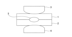
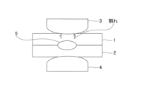
- this welding method as shown in Fig. 1, two overlapping steel plates 1 and 2 are made into a plate assembly, and the upper and lower sides of the plate assembly are sandwiched between a pair of electrodes 3 and 4.
- This is a method of joining steel plates by applying a welding current between the upper and lower electrodes while applying pressure with a pair of electrodes 3 and 4.
- a dot-like weld 5 is obtained by using resistance heat generated by flowing a welding current.
- This dot-shaped weld 5 is called a nugget, and is a part where both steel plates 1 and 2 melt and solidify at the contact point of the steel plates when welding current is applied to the overlapped steel plates. Joined in dots. Note that FIG. 1 shows, as an example, two steel plates stacked on top of each other.
- surface-treated steel sheets include galvanizing, such as electrogalvanizing, hot-dip galvanizing (including alloyed hot-dip galvanizing), and zinc alloy plating that contains elements such as aluminum and magnesium in addition to zinc.
- galvanizing such as electrogalvanizing, hot-dip galvanizing (including alloyed hot-dip galvanizing), and zinc alloy plating that contains elements such as aluminum and magnesium in addition to zinc.
- cracks in the weld zone occur when the low-melting point metal plating layer on the surface of the steel plate melts during welding, and when tensile stress due to the pressure applied by the electrode or the thermal expansion and contraction of the steel plate is applied to the weld zone, the melted low-melting metal plating layer melts. It is thought that the cracks are caused by so-called liquid metal embrittlement, in which metal at the melting point invades the grain boundaries of the base material of the surface-treated steel sheet, lowering the grain boundary strength and causing cracks.
- Such cracks tend to occur when a large deformation is applied to the welded part.
- the steel plates 1 and 2 on the side that are in contact with the electrodes 3 and 4 as shown in FIG. It is more likely to occur on surfaces.
- it is important to secure a nugget with a large nugget diameter During welding, it may not be possible to secure sufficient current density in the area to be welded due to construction disturbances such as shunting to welding points near the area to be welded or wear and tear of the electrode due to continuous welding points. be. In such a case, the amount of heat input decreases, making it difficult to ensure a predetermined nugget diameter.
- Patent Document 1 proposes a method of suppressing the occurrence of cracks in spot welding of high-strength plated steel sheets by appropriately adjusting the welding energization time and the holding time after welding energization.
- the energization pattern is energized in three or more stages, and welding conditions such as energization time and welding current are adjusted so that the appropriate current range is 1.0 kA or more, preferably 2.0 kA or more, Allow cooling time between each stage. Accordingly, methods have been proposed to suppress the occurrence of cracks.
- appropriate current range refers to a current range that can stably form a nugget diameter that is equal to or greater than a desired nugget diameter and has a residual melting pressure of 0.05 mm or greater.
- Patent Document 3 proposes a method of suppressing the occurrence of cracks by appropriately adjusting the holding time after energization.
- Patent Document 4 proposes a method of improving the cross tensile strength of a joint by forming a nugget through main energization and then applying a short-time post-energization that does not involve growth of the nugget.
- Patent Document 1 and Patent Document 2 the influence of construction disturbances is not considered, and there are cases where the countermeasures are insufficient when considering the actual construction work during automobile assembly.
- Patent Document 3 is a technology that can suppress cracks that occur during the time from the end of energization until the electrode is opened, but does not mention cracks that occur during energization, and it is difficult to prevent such cracks. There was a case.
- Patent Document 4 does not mention cracks during welding, and under conditions where a large nugget diameter is formed by main energization, the steel plate surface may be greatly deformed and cracks may occur.
- the problem of difficulty in stably securing large nuggets while suppressing the occurrence of cracks during welding in surface-treated steel sheets is not limited to resistance spot welding of automotive steel sheets. , also exists in resistance spot welding of other steel plates.
- the present invention has been made in view of the above circumstances, and provides a resistance spot welding method that can stably secure nuggets with a large nugget diameter while suppressing cracking during welding of surface-treated steel sheets.
- the purpose is to provide.
- the process during resistance spot welding is divided into two processes: the first energization process and the second energization process.
- the first energization step energization is applied within a range that does not cause extreme deformation to form a nugget with a certain nugget diameter.
- the current value is adjusted to suppress deformation, a sufficiently large nugget will not be formed, and for example, if there is a disturbance that reduces the nugget diameter, it will not be possible to secure a nugget with a predetermined nugget diameter. Problems may arise. Therefore, in the second energization step, the nugget is expanded by adjusting the energization conditions so as not to cause large deformation in the welded portion. This makes it possible to stably secure a nugget with a large nugget diameter while suppressing the occurrence of cracks during resistance spot welding.
- the energization conditions in the first energization step and the second energization step are shown below.
- the heat input can be adjusted by adjusting the current value and the energization pattern, thereby making it possible to firmly bond the pressure welding part (corona bond part) around the nugget.
- This makes it possible to suppress the scale of scattering (that is, the amount of molten metal that scatters) in the subsequent second energization process, which reduces the deformation of the welded part, and as a result, it is possible to suppress the occurrence of cracks. Become.
- the nugget can be enlarged by applying current at a current value higher than the current value in the first energization process, but if the current is applied for a long time, the heat input will be excessive and the weld will be significantly deformed. It will happen. Therefore, by creating an energization pattern that repeats short-time energization and short-time cooling, it is possible to expand the nugget in stages while suppressing the deformation of the welded part, making it possible to suppress the occurrence of cracks during welding. becomes.
- the scale of the splintering (that is, the amount of molten metal scattered due to splintering) can be kept small by applying current for a short time. Therefore, the deformation of the welded portion is reduced, and as a result, it is possible to suppress the occurrence of cracks during welding.
- the nugget can be effectively expanded, that is, the nugget diameter can be increased while suppressing the scale of scattering.
- a resistance spot welding method in which two or more steel plates, including at least one zinc-based plated steel plate, are overlapped and joined by resistance spot welding,
- the resistance spot welding includes a first energization process and a second energization process,
- the first energization step when the thickness of the thinnest steel plate among the stacked steel plates is t (mm), a nugget with a thickness of 3.0 ⁇ t (mm) or more and 4.5 ⁇ t (mm) or less
- a nugget with a diameter is formed by setting the current value and energization time
- a multi-step process of n stages (n is an integer of 2 or more) consisting of a cooling step in which the non-energized state is maintained for 10 ms or more and less than 160 ms, and an energization step in which the current is applied for 20 ms or more and less than 200
- the first energization step is multistage energization of m stages (m is an integer of 2 or more);
- the current value of each stage in the multistage energization is I1' to Im' (kA), and the current value I1' of the first stage is the same as the current value Is at the start of the energization, and the current value Im of the mth stage is
- the resistance spot welding method according to [2] wherein when ' is the same as the current value If at the end of the energization, the current values I1' to Im' of each stage in the multi-stage energization satisfy equation (4).
- the resistor according to any one of [1] to [4], wherein the amount of expansion of the nugget diameter in the second energization step, represented by (N2-N1), is 0.1 ⁇ t (mm) or more. Spot welding method.
- the zinc-based plated steel sheet is a high-strength steel sheet having a Ceq expressed by formula (5) of 0.20% or more and a tensile strength of 780 MPa or more, any one of [1] to [5].
- the resistance spot welding method described in item 1. Ceq (%) C+Si/30+Mn/20+2P+4S...(5)
- the element symbol in formula (5) indicates the content (mass%) of each element.
- the present invention it is possible to stably form a nugget with a large nugget diameter while suppressing the occurrence of cracking during welding of a surface-treated steel sheet, and therefore, it has a significant industrial effect.
- FIG. 1 is a cross-sectional view schematically showing an example of resistance spot welding according to the present invention.
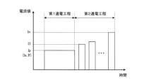
- FIG. 2 is a diagram illustrating a first embodiment of the energization pattern of the resistance spot welding method of the present invention.
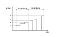
- FIG. 3 is a diagram illustrating a second embodiment of the energization pattern of the resistance spot welding method of the present invention.
- FIG. 4 is a diagram illustrating a third embodiment of the energization pattern of the resistance spot welding method of the present invention.
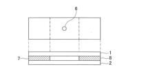
- FIG. 5 is a diagram showing a resistance spot welding test piece in an example of the present invention, with the upper side being a plan view and the lower side being a side view.
- FIG. 1 is a cross-sectional view schematically showing an example of resistance spot welding according to the present invention.
- FIG. 2 is a diagram illustrating a first embodiment of the energization pattern of the resistance spot welding method of the present invention.
- FIG. 3 is a diagram illustrating a second embodiment of the ener
- FIG. 6 is a diagram showing a resistance spot welding test piece in an example of the present invention, with the upper side being a plan view and the lower side being a side view.
- FIG. 7 is a diagram showing a resistance spot welding test piece in an example of the present invention, with the upper side being a plan view and the lower side being a side view.
- FIG. 8 is a cross-sectional view schematically showing an example of occurrence of cracks during conventional resistance spot welding.
- the resistance spot welding method of the present invention involves stacking two or more steel plates, including at least one galvanized steel plate, to form a plate assembly, and applying pressure while sandwiching this plate assembly between a pair of welding electrodes, as described below. energize under the welding conditions. Thereby, a nugget is formed between the steel plates by resistance heat generation, and the superposed steel plates are joined together.
- this resistance spot welding method it is possible to manufacture a welded joint that can stably form a nugget with a large nugget diameter while suppressing the occurrence of cracks during resistance spot welding, even for plate sets including zinc-based plated steel sheets.
- the resistance spot welding process includes a first energization process and a second energization process.
- first energization process a welded portion having a nugget diameter of 3.0 ⁇ t (mm) or more and 4.5 ⁇ t (mm) or less is formed.
- second energization process the nugget formed in the first energization process is expanded by performing a multi-step process consisting of a cooling process in which a non-energized state is maintained and an energization process in which electricity is applied in a specific pattern.
- the nugget diameter is 3.0 ⁇ t (mm) or more and 4.5 ⁇ t (mm) or less.
- a nugget is formed by setting at least a current value Ip (kA) and a current application time tp (ms) and applying current.
- the energization conditions are such that a nugget is formed without causing any scattering.
- the target nugget diameter for setting the current value Ip (kA) and the current application time tp refers to the nugget diameter when welding is performed without disturbance.
- the diameter of the nugget to be formed is less than 3.0 ⁇ t (mm)
- the diameter of the nugget formed in the first energization step is too small, so the nugget cannot be effectively and sufficiently expanded in the second energization step later. becomes difficult. As a result, it becomes difficult to secure a nugget with a large nugget diameter.
- the diameter of the nugget to be formed exceeds 4.5 ⁇ t (mm), the heat input due to energization will be excessive, deforming the welded portion and easily causing cracks. Therefore, the diameter of the nugget formed in the first energization step is set to 3.0 ⁇ t (mm) or more and 4.5 ⁇ t (mm) or less.
- the diameter of the nugget formed in the first energization step is preferably in the range of 4.0 ⁇ t (mm) to 4.5 ⁇ t (mm). If it is in the range of 4.0 ⁇ t (mm) to 4.5 ⁇ t (mm), it is possible to obtain a more remarkable effect of enlarging the nugget diameter without causing cracks in the subsequent second energization step. can.
- the above “t” refers to the thickness (mm) of the steel plate.
- the thickness of the thinnest steel plate among the stacked steel plates constituting the plate set is defined as t.
- the thickness of the thinnest steel plate among them is t
- the number of nuggets formed on each mating surface of the stacked steel plates is t.
- the current value in the first energization step is set so that the minimum nugget diameter becomes a nugget diameter of 3.0 ⁇ t (mm) or more and 4.5 ⁇ t (mm) or less. and set the energization time.
- the current value, energization time, and pressing force in the first energization step can be appropriately selected from welding conditions that can ensure the above nugget diameter.
- the welding conditions for resistance spot welding in the first energization step are: current value Ip is 4 to 10 kA, energization time tp is 100 to 500 ms, It is preferable that the pressing force be appropriately selected from the range of 1.5 kN to 8.0 kN depending on the board assembly.
- the first energization step may be controlled to the following energization pattern.
- the current may be applied so that the current value from the start of energization to the end of energization in the first energization process is constant.
- the current may be variably energized so that the current value from the start of energization to the end of energization in the first energization step satisfies equation (3) described below.
- First energization pattern (preferred conditions) Referring to FIG. 2, an example in which the current value Ip in the first energization step is constant (ie, constant current) will be described as the first energization pattern.
- the current value at the start of energization is Is (kA) and the current value at the end of energization is If (kA)
- the current value Is at the start of energization and the current value at the end of energization are The current can be applied so that the current value If at the end of the process is constant.
- a welded portion having a nugget diameter of 3.0 ⁇ t (mm) or more and 4.5 ⁇ t (mm) or less is formed.
- the above-mentioned "keeping the current value constant” refers to energization that is performed without changing the current value from the time when energization starts until the time when energization ends, and is set to be constant.
- the current during energization in the first energization step can be controlled so as to satisfy equation (3), and can be made variable.
- Examples of methods for controlling the current so that it is variable include “multi-stage energization (see FIG. 3)" and “up-slope energization (see FIG. 4).”
- By variably controlling the current to increase in this way it is possible to more firmly join the pressure welding part around the nugget in the first energization process, and to suppress the occurrence of expulsion in the second energization process, Furthermore, even if scattering occurs, the scale of the scattering can be kept small. This reduces deformation of the welded portion, and as a result, it is possible to suppress the occurrence of cracks.
- the first energization step when the first energization step is variably energized, the first energization step can be energized in m stages (m is an integer of 2 or more).
- the current value of each stage in this multi-stage energization be I1' to Im' (kA), and the current value I1' (kA) of the first stage is the same as the current value Is (kA) at the start of the energization, and m
- the current value Im' (kA) of the stage is the same as the current value If (kA) at the end of the above-mentioned energization, the current value I1' to Im' of each stage in the multi-stage energization of the first energization step is (4 ) is controlled to satisfy the formula.
- the energization time in the first energization step is preferably controlled so that the total energization time in each stage is within the range of the above-mentioned energization time tp (100 to 500 ms).
- m indicating multiple stages shall be an integer of 2 or more. From the viewpoint of preventing the management of welding conditions during construction from becoming too complicated, m is preferably 5 or less.
- the energization in the first energization step is an upslope energization in which the current value is continuously increased from the current value Is at the start of energization to the current value If at the end of energization. I can do it.
- I can do it.
- ⁇ Second energization process> After the first energization step described above, a second energization step is performed. At this time, it is important to gradually increase the current value of repeated energization in the second energization step. By gradually increasing the current value, the nugget can be effectively enlarged.
- the second energization step consists of a cooling step in which the non-energized state is maintained for 10 ms or more and less than 160 ms, and an energization step in which the current is applied for 20 ms or more and less than 200 ms (n is 2 or more). (integer) multi-step process.
- the current value of the first stage energization process is I1 (kA) and the current value of the nth stage (final stage) energization process is In (kA)
- the current value of the first stage Adjustment is made so that I1 is greater than or equal to the current value in the first energization step, and the current values I1 to In of each stage satisfy equations (1) and (2).
- the "current value of the first energization process” in the above "the current value I1 of the first stage is greater than or equal to the current value of the first energization process” means “the current value of the first energization process” in the case of a constant current (see Figure 2). In the case of a variable current (see FIGS. 3 and 4), it refers to the "current value If at the end of energization.”
- the non-current time in the cooling step is less than 10 ms, a sufficient cooling effect cannot be obtained and large deformation of the welded portion is likely to occur, resulting in cracking.
- the non-energization time is 160 ms or more, the effect of multi-stage operation, that is, the effect of enlarging the nugget due to repeated energization cannot be sufficiently obtained. Therefore, the non-energizing time in the cooling process at each stage is set to 10 ms or more and less than 160 ms.
- the non-energizing time is preferably 10 to 120 ms.
- the energization time in the energization process is less than 20 ms, a sufficient nugget enlarging effect cannot be obtained due to insufficient heat input.
- the energization time is 200 ms or more, excessive heat input is applied with one energization, which tends to cause large deformation of the welded part, and cracks are likely to occur. Therefore, the energization time of the energization process in each stage is set to 20 ms or more and less than 200 ms.
- the nugget is expanded in the second energization step as described above. If you want to achieve a more remarkable effect of stably enlarging the nugget diameter while suppressing deformation of the weld, the non-energizing time in the cooling process at each stage of the second energizing process is 10 to 80 ms, and the energizing process is It is preferable that the current application time be 20 to 100 ms.
- the non-energizing time in the cooling step is more preferably 10 ms or more and less than 80 ms, still more preferably 10 to 60 ms, even more preferably 10 to 20 ms.
- the current value of each step of the energization step in the second energization step satisfies the following condition in addition to equation (1). Specifically, when the current value when energizing the kth stage is Ik (kA), and the current value when energizing the (k+1)th stage is I(k+1) (kA). , I(k+1) ⁇ 1.3 ⁇ Ik.
- k is an integer greater than or equal to 1 and less than or equal to n-1. Within this range, it is possible to suppress a sudden increase in heat input, and it is easier to suppress deformation of the welded part due to occurrence of large expulsions.
- the number of steps (number of stages) performed in multiple stages in the second energization step is preferably 2 or more and 10 or less. If the number of stages exceeds 10, the nugget expansion effect is saturated, making it difficult to obtain a large effect, and the total time of the entire welding process becomes longer. Therefore, from the viewpoint of construction efficiency, the number of stages is preferably 10 or less.
- the diameter of the nugget formed after the first energization step is N1 (mm)
- the diameter of the nugget formed after the end of the first energization step and the second energization step is N2 (mm).
- the value of (N2-N1) which is the amount of expansion of the nugget diameter in the second energization step, is preferably 0.1 ⁇ t (mm) or more.
- the value of (N2-N1) is more preferably 0.3 ⁇ t (mm) or more, and still more preferably 0.5 ⁇ t (mm) or more.
- (N2-N1) is more preferably 2.5 ⁇ t (mm) or less, and even more preferably 2.0 ⁇ t (mm) or less.
- the present invention is a surface-treated steel sheet having a metal plating layer on either both sides or one side of the plate assembly that is in contact with each welding electrode (upper electrode, lower electrode) arranged on the upper side and lower side of the plate assembly.
- each welding electrode upper electrode, lower electrode
- both sides of the plate set in contact with each welding electrode refers to the two outermost steel plates of the plate set made up of a plurality of steel plates that are in contact with the upper and lower electrodes.
- the above-mentioned “one side of the plate assembly in contact with each welding electrode” refers to the two outermost plates of the plate assembly made up of multiple steel plates that are in contact with the upper electrode or the lower electrode. Refers to one of the steel plates.
- the melting point of the metal plating layer is lower than the melting point of the base material of the surface-treated steel sheet.
- surface-treated steel sheets include zinc plating, such as electrogalvanizing, hot-dip galvanizing (including alloyed hot-dip galvanizing), and zinc alloys containing elements such as aluminum and magnesium in addition to zinc.
- a steel plate that has a metal plating layer such as plating on the surface of the base material (substrate steel plate).
- a surface-treated steel sheet is referred to as a "zinc-based plated steel sheet.” Therefore, in the present invention, at least one of the plurality of steel plates constituting the above plate set is a zinc-based plated steel plate.
- the element symbol in formula (5) indicates the content (mass%) of each element, and is set to 0 when the element is not contained.
- the carbon equivalent (Ceq) is preferably 0.60% or less, more preferably 0.50% or less.
- the welding electrodes (upper electrode and lower electrode) placed on the upper and lower sides of the plate assembly are used.
- the zinc-based plated steel plates in contact with either of them it is sufficient that any one of them has a carbon equivalent of 0.20% or more.
- composition of the high-strength galvanized steel sheet used in the present invention may be adjusted as appropriate so as to obtain the above-mentioned carbon equivalent (Ceq) range and tensile strength.
- the thickness of the steel plate to be resistance spot welded is not particularly limited.
- it is preferably within the range of 0.5 mm or more and 3.0 mm or less.
- a steel plate having a thickness within this range can be suitably used as an automobile member.
- the two or more steel plates to be resistance spot welded may be of the same type and shape, or may be of different types and shapes.
- a surface-treated steel sheet having a metal plating layer and a steel sheet having no metal plating layer may be stacked on top of each other.
- FIG. 1 shows a state in which a plate set of two overlapping steel plates is joined by the resistance spot welding method of the present invention.
- a pair of welding electrodes namely welding electrode 4 (lower electrode) placed on the lower side of the plate assembly and welding electrode 3 (upper electrode) placed on the upper side of the plate assembly, are overlapped.
- the steel plates (lower steel plate 2 and upper steel plate 1) are sandwiched and energized under the above-mentioned welding conditions while being pressurized.
- the number of overlapping steel plates is preferably four or less.
- the apparatus for carrying out the resistance spot welding method of the present invention is not particularly limited as long as it applies pressure using a lower electrode and an upper electrode and controls the applied force.
- devices such as air cylinders and servo motors can be used.
- the configuration for supplying current and controlling the current value during energization is not particularly limited, and the present invention can be applied to both direct current and alternating current. In the case of alternating current, "current" means "effective current.”
- the types of the tips of the lower electrode and the upper electrode are not particularly limited. Examples include DR type (dome radius type), R type (radius type), D type (dome type), etc. described in JIS C 9304:1999.
- the tip diameter of each electrode is, for example, 4 mm to 16 mm.
- the radius of curvature is, for example, 10 mm to 400 mm, and a flat electrode with a flat tip can also be used.
- Table 2-1 shows the welding conditions when the first energization process is conducted at a constant current value, and the second energization process is conducted in a multi-step process consisting of a cooling process and an energization process.
- Table 3-1 shows the welding conditions when the first energization process is energized at a variable current value (multistage energization), and the second energization process is energized in a multistage process consisting of a cooling process and an energization process. .
- Table 4-1 shows the welding conditions when the first energization process is energized with a variable current value (up slope energization), and the second energization process is energized in a multi-step process consisting of a cooling process and an energization process. be.
- the "second energization process" shown in Table 2-1, Table 3-1, and Table 4-1 is a multi-step process of n stages (n is an integer of 2 or more) consisting of a cooling process and an energization process. .
- the "first stage current value I1' (kA)” refers to the “current value Is (kA) at the start of energization.”
- Resistance spot welding was performed at room temperature, with the welding electrodes (lower electrode, upper electrode) constantly water-cooled. Both the lower electrode and the upper electrode had a tip diameter (tip diameter) of 6 mm, a radius of curvature of 40 mm, and were DR-shaped electrodes made of chromium copper.
- the pressurizing force was controlled by driving the upper electrode with a servo motor, and DC power was supplied during energization.
- FIGS. 5 to 7 a case will be described in which a welded joint is manufactured under the above three disturbance conditions.
- Each figure shows a test specimen in which resistance spot welded steel plates are stacked one on top of the other, with the upper figure being a plan view and the lower figure being a side view.
- a welded joint with the disturbance condition of "no disturbance” was manufactured as follows. As shown in Figure 5, two steel plates (upper steel plate 1, lower steel plate 2) with a size of 30 mm x 100 mm (short side x long side) made from the above steel plate were prepared, and the steel plates were stacked and tested. A welded joint was prepared by welding the welded part 6 at the center of the specimen under the conditions shown in Table 2-1, Table 3-1, and Table 4-1. Using the welded portion 6 of the obtained welded joint, the nugget diameter and the presence or absence of cracking were observed.
- a welded joint with a disturbance condition of "plate gap” was manufactured as follows. As shown in Fig. 6, two steel plates (upper steel plate 1, lower steel plate 2) with a size of 30 mm x 100 mm (short side x long side) made from the above steel plates are prepared, and the space between the two steel plates is Spacers 7 and 8 having a thickness of 1.6 mm and a size of 30 mm x 25 mm (long side x short side) were sandwiched between both ends of the steel plate to prepare a test specimen. Welded joints were prepared by welding the welded part 6 at the center of the test specimen under the conditions shown in Table 2-1, Table 3-1, and Table 4-1. Using the welded portion 6 of the obtained welded joint, the nugget diameter and the presence or absence of cracking were observed.
- a test specimen with the disturbance condition of "previously struck points” was prepared as follows. As shown in Figure 7, two steel plates (upper steel plate 1, lower steel plate 2) with a size of 30 mm x 100 mm (short side x long side) made from the above steel plate were prepared, and the steel plates were stacked and tested. As a body. Welded points 9 and 10 each having a nugget diameter of 5 mm were placed at positions 20 mm away from the center of the test piece in the longitudinal direction, and then the welded parts 6 at the center of the test piece were welded in Tables 2-1, 3-1, and 4. A welded joint was produced by welding under the conditions shown in -1. Using the welded portion 6 of the obtained welded joint, the nugget diameter and the presence or absence of cracking were observed.
- nugget diameter (N1) after the first energization process a welding test only for the first energization process was conducted in advance in a test under each disturbance condition, and the nugget diameter was measured by observing the cross section.
- the nugget diameter between the steel plates was measured. The obtained measured values are shown in the "Nugget diameter N1 after first energization step" column in Tables 2-2, 3-2, and 4-2.
- the nugget diameter (N2) after the second energization step was measured in the same manner as described above using each welded joint obtained by conducting a welding test under the above three disturbance conditions.
- the obtained measured values are shown in the "Nugget diameter N2 after second energization step" column in Tables 2-2, 3-2, and 4-2, respectively.
Landscapes
- Engineering & Computer Science (AREA)
- Mechanical Engineering (AREA)
- Resistance Welding (AREA)
Abstract
Description
[1] 少なくとも1枚の亜鉛系めっき鋼板を含む2枚以上の鋼板を重ね合わせて抵抗スポット溶接で接合する抵抗スポット溶接方法であって、
前記抵抗スポット溶接は、第1通電工程と第2通電工程とを有し、
前記第1通電工程では、重ね合わせた前記鋼板のうち、最も薄い鋼板の板厚をt(mm)とするとき、3.0√t(mm)以上4.5√t(mm)以下のナゲット径となるナゲットを電流値と通電時間を設定することで形成し、
前記第2通電工程では、
10ms以上160ms未満の間、無通電状態を保持する冷却工程と、20ms以上200ms未満の間、通電する通電工程とからなるn段(nは2以上の整数)の多段階の工程とし、
さらに、前記多段階における、1段目の前記通電工程の電流値をI1(kA)、n段目の前記通電工程の電流値をIn(kA)とするとき、1段目の電流値I1は前記第1通電工程の電流値以上であり、かつ各段の電流値I1~Inが(1)式および(2)式を満たす、抵抗スポット溶接方法。
I1 ≦I2 ≦ ・・・・ ≦ In …(1)
I1<In …(2)
[2] 前記第1通電工程は、通電開始時の電流値をIs(kA)、通電終了時の電流値をIf(kA)とするとき、
前記通電開始時から前記通電終了時までの電流値が一定となるように通電し、
あるいは、前記通電開始時の電流値Isおよび前記通電終了時の電流値Ifが(3)式を満たすように可変に通電する、[1]に記載のスポット溶接方法。
If >Is …(3)
[3] 前記第1通電工程を可変に通電するときには、前記第1通電工程はm段(mは2以上の整数)の多段通電であり、
前記多段通電での各段の電流値をI1´~Im´(kA)とし、かつ、1段目の電流値I1´が前記通電開始時の電流値Isと同一およびm段目の電流値Im´が前記通電終了時の電流値Ifと同一とするとき、前記多段通電での各段の電流値I1´~Im´が(4)式を満たす、[2]に記載の抵抗スポット溶接方法。
I1´ < I2´ < I3´ < ・・・ < Im´ …(4)
[4] 前記第1通電工程を可変に通電するときには、
前記通電開始時の電流値Isから前記通電終了時の電流値Ifまで、連続的に電流値を増加させるアップスロープ通電である、[2]に記載の抵抗スポット溶接方法。
[5] 前記第1通電工程の終了後に形成されるナゲット径をN1(mm)、前記第1通電工程および前記第2通電工程の終了後に形成されるナゲット径をN2(mm)とするとき、
(N2-N1)で表される前記第2通電工程でのナゲット径の拡大量が0.1√t(mm)以上である、[1]~[4]のいずれか1つに記載の抵抗スポット溶接方法。
[6] 前記亜鉛系めっき鋼板は、(5)式で表されるCeqが0.20%以上であり、引張強さが780MPa以上の高強度鋼板である、[1]~[5]のいずれか1つに記載の抵抗スポット溶接方法。
Ceq(%)=C+Si/30+Mn/20+2P+4S …(5)
ここで、(5)式中の元素記号は、各元素の含有量(質量%)を示す。
第1通電工程では、重ね合わせた鋼板のうち、最も薄い鋼板の板厚をt(mm)とするとき、3.0√t(mm)以上4.5√t(mm)以下のナゲット径となるナゲットを、少なくとも電流値Ip(kA)と通電時間tp(ms)を設定し、通電することで形成する。この際、散りを発生させることなくナゲットを形成する通電条件とする。電流値Ip(kA)と通電時間tpを設定するための目標ナゲット径は、外乱のない状態で溶接を行った場合のナゲット径を指す。
図2を参照し、第1の通電パターンとして、第1通電工程の電流値Ipを一定(すなわち、定電流)とする例を説明する。
図2に示すように、第1通電工程においては、通電開始時の電流値をIs(kA)、通電終了時の電流値をIf(kA)とするとき、通電開始時の電流値Isおよび通電終了時の電流値Ifが一定となるように通電することができる。この通電により、3.0√t(mm)以上4.5√t(mm)以下のナゲット径となる溶接部を形成する。上記の「電流値を一定とする」とは、通電開始時から通電終了時までの電流値を変化させず、一定となるよう設定して行う通電を指す。
図3および図4を参照し、第2および第3の通電パターンとして、第1通電工程の電流値Ipを可変とする例を説明する。
第1通電工程においては、通電開始時の電流値をIs(kA)、通電終了時の電流値をIf(kA)とするとき、通電開始時の電流値Isおよび通電終了時の電流値Ifが(3)式を満たすように可変に通電することができる。この通電により、3.0√t(mm)以上4.5√t(mm)以下のナゲット径となる溶接部を形成する。
If >Is …(3)
図3に示すように、第1通電工程を可変に通電するときには、第1通電工程の通電をm段(mは2以上の整数)の多段通電とすることができる。この多段通電での各段の電流値をI1´~Im´(kA)とし、かつ、1段目の電流値I1´(kA)が上記通電開始時の電流値Is(kA)と同一およびm段目の電流値Im´(kA)が上記通電終了時の電流値If(kA)と同一とするとき、第1通電工程の多段通電での各段の電流値I1´~Im´が(4)式を満たすように制御する。
I1´<I2´<I3´<・・・<Im´ (4)
図4に示すように、第1通電工程の通電は、上記の通電開始時の電流値Isから上記の通電終了時の電流値Ifまで、連続的に電流値を増加させるアップスロープ通電とすることができる。これにより、第1通電工程においてナゲット周囲の圧接部を強固に接合し、後の第2通電工程において散りの規模を小さく抑えることができる。そのため、溶接部の変形が小さくなり、その結果、割れの発生を抑えることが可能となる。
上述の第1通電工程の後、第2通電工程を行う。この際、第2通電工程において繰り返し通電の電流値を徐々に大きくすることが重要である。電流値を徐々に大きくすることにより、ナゲットを効果的に拡大することができる。
I1≦I2≦I3≦・・・・≦In …(1)
I1<In …(2)
冷却工程における無通電時間が10ms未満の場合は、十分な冷却効果を得ることができず、溶接部の大きな変形が発生しやすくなるため、割れが発生しやすい。無通電時間が160ms以上の場合には、多段階にすることに効果、すなわち繰り返し通電によるナゲットの拡大効果を十分に得られない。したがって、各段における冷却工程の無通電時間は、10ms以上160ms未満とする。当該無通電時間は、好ましくは10~120msとする。
通電工程における通電時間が20ms未満の場合は、入熱不足によりナゲットの拡大効果を十分に得られない。通電時間が200ms以上の場合は、一度の通電で過大な入熱を加えることにより溶接部の大きな変形が発生しやすく、割れが発生しやすい。したがって、各段における通電工程の通電時間は、20ms以上200ms未満とする。
具体的には、段数:k段目の通電での電流値をIk(kA)、段数:(k+1)段目の通電での電流値をI(k+1)(kA)としたとき、I(k+1)≦1.3×Ikとすることが好ましい。ここで、kは、1以上n-1以下の整数とする。この範囲であれば、急激な入熱の上昇を抑制することができ、大きな散りの発生による溶接部の変形をより抑制しやすい。
本発明で径の大きなナゲットを確保する観点からは、第1通電工程終了後に形成されるナゲット径をN1(mm)、第1通電工程および第2通電工程終了後に形成されるナゲット径をN2(mm)とするとき、第2通電工程でのナゲット径の拡大量である(N2-N1)の値は0.1√t(mm)以上であることが好ましい。(N2-N1)の値は、より好ましくは0.3√t(mm)以上であり、さらに好ましくは0.5√t(mm)以上である。
本発明は、板組の上側および下側に配置される各溶接電極(上電極、下電極)と接する板組の両面、もしくは片面のいずれか一方が、金属めっき層を有する表面処理鋼板である板組の抵抗スポット溶接方法に適用される。ここで、上記の「各溶接電極と接する板組の両面」とは、上電極および下電極と接する、複数の鋼板で構成される板組のうち最も外側に配置される2枚の鋼板を指す。また、上記の「各溶接電極と接する板組の片面のいずれか一方」とは、上電極あるいは下電極と接する、複数の鋼板で構成される板組のうち最も外側に配置される2枚の鋼板のいずれか一方の鋼板を指す。なお、金属めっき層の融点は、表面処理鋼板の母材の融点よりも低いものを対象とすることが好ましい。
Ceq(%)=C+Si/30+Mn/20+2P+4S …(5)
ここで、(5)式中の元素記号は、各元素の含有量(質量%)を示し、元素が含有されていない場合は0とする。
第1通電工程後のナゲット径(N1)については、各外乱条件における試験で、第1通電工程のみの溶接試験を事前に実施し、断面観察を行うことでナゲット径を測定した。
ここでは、溶接部を切断した断面をエッチング後、光学顕微鏡により観察し、鋼板間におけるナゲット径を測定した。得られた測定値を、表2-2、表3-2および表4-2中の「第1通電工程後のナゲット径N1」欄に示した。
割れ(LME割れ)の評価は、上記の3つの外乱条件で溶接試験を実施して得られた各溶接継手を用いて行った。溶接部断面を光学顕微鏡で観察した結果、溶接部表面に200μm以上の割れが観察された場合に、「割れあり」と評価した。一方、200μm以上の割れが観察されなかった場合に、「割れなし」と評価した。「割れあり」と評価された場合には表2-2、表3-2および表4-2中に「あり」と示し、「割れなし」と評価された場合には表2-2、表3-2および表4-2中に「なし」と示した。
判定については、上記の3つの外乱条件の全てで、溶接後のナゲット径(N2)が4.5√t(mm)以上、かつ割れが発生しなかったものを「〇(合格)」と評価した。一方、それ以外のものを「×(不合格)」と評価した。評価結果を表2-2、表3-2および表4-2に示した。


2 下鋼板
3 上電極
4 下電極
5 ナゲット
6 溶接部
7、8 スペーサ
9、10 既溶接点
Claims (7)
- 少なくとも1枚の亜鉛系めっき鋼板を含む2枚以上の鋼板を重ね合わせて抵抗スポット溶接で接合する抵抗スポット溶接方法であって、
前記抵抗スポット溶接は、第1通電工程と第2通電工程とを有し、
前記第1通電工程では、重ね合わせた前記鋼板のうち、最も薄い鋼板の板厚をt(mm)とするとき、3.0√t(mm)以上4.5√t(mm)以下のナゲット径となるナゲットを電流値と通電時間を設定することで形成し、
前記第2通電工程では、
10ms以上160ms未満の間、無通電状態を保持する冷却工程と、20ms以上200ms未満の間、通電する通電工程とからなるn段(nは2以上の整数)の多段階の工程とし、
さらに、前記多段階における、1段目の前記通電工程の電流値をI1(kA)、n段目の前記通電工程の電流値をIn(kA)とするとき、1段目の電流値I1は前記第1通電工程の電流値以上であり、かつ各段の電流値I1~Inが(1)式および(2)式を満たす、抵抗スポット溶接方法。
I1 ≦I2 ≦ ・・・・ ≦ In …(1)
I1<In …(2) - 前記第1通電工程は、通電開始時の電流値をIs(kA)、通電終了時の電流値をIf(kA)とするとき、
前記通電開始時から前記通電終了時までの電流値が一定となるように通電し、
あるいは、前記通電開始時の電流値Isおよび前記通電終了時の電流値Ifが(3)式を満たすように可変に通電する、請求項1に記載のスポット溶接方法。
If >Is …(3) - 前記第1通電工程を可変に通電するときには、前記第1通電工程はm段(mは2以上の整数)の多段通電であり、
前記多段通電での各段の電流値をI1´~Im´(kA)とし、かつ、1段目の電流値I1´が前記通電開始時の電流値Isと同一およびm段目の電流値Im´が前記通電終了時の電流値Ifと同一とするとき、前記多段通電での各段の電流値I1´~Im´が(4)式を満たす、請求項2に記載の抵抗スポット溶接方法。
I1´ < I2´ < I3´ < ・・・ < Im´ …(4) - 前記第1通電工程を可変に通電するときには、
前記通電開始時の電流値Isから前記通電終了時の電流値Ifまで、連続的に電流値を増加させるアップスロープ通電である、請求項2に記載の抵抗スポット溶接方法。 - 前記第1通電工程の終了後に形成されるナゲット径をN1(mm)、前記第1通電工程および前記第2通電工程の終了後に形成されるナゲット径をN2(mm)とするとき、
(N2-N1)で表される前記第2通電工程でのナゲット径の拡大量が0.1√t(mm)以上である、請求項1~4のいずれか1項に記載の抵抗スポット溶接方法。 - 前記亜鉛系めっき鋼板は、(5)式で表されるCeqが0.20%以上であり、引張強さが780MPa以上の高強度鋼板である、請求項1~4のいずれか1項に記載の抵抗スポット溶接方法。
Ceq(%)=C+Si/30+Mn/20+2P+4S …(5)
ここで、(5)式中の元素記号は、各元素の含有量(質量%)を示す。 - 前記亜鉛系めっき鋼板は、(5)式で表されるCeqが0.20%以上であり、引張強さが780MPa以上の高強度鋼板である、請求項5に記載の抵抗スポット溶接方法。
Ceq(%)=C+Si/30+Mn/20+2P+4S …(5)
ここで、(5)式中の元素記号は、各元素の含有量(質量%)を示す。
Priority Applications (5)
| Application Number | Priority Date | Filing Date | Title |
|---|---|---|---|
| EP23839323.5A EP4494800A4 (en) | 2022-07-14 | 2023-05-29 | SPOT WELDING PROCESS |
| KR1020247040768A KR20250002801A (ko) | 2022-07-14 | 2023-05-29 | 저항 스폿 용접 방법 |
| CN202380046661.5A CN119365289A (zh) | 2022-07-14 | 2023-05-29 | 电阻点焊方法 |
| JP2023547356A JP7522977B2 (ja) | 2022-07-14 | 2023-05-29 | 抵抗スポット溶接方法 |
| MX2024015448A MX2024015448A (es) | 2022-07-14 | 2024-12-12 | Metodo de soldadura por puntos por resistencia |
Applications Claiming Priority (2)
| Application Number | Priority Date | Filing Date | Title |
|---|---|---|---|
| JP2022-112894 | 2022-07-14 | ||
| JP2022112894 | 2022-07-14 |
Publications (1)
| Publication Number | Publication Date |
|---|---|
| WO2024014146A1 true WO2024014146A1 (ja) | 2024-01-18 |
Family
ID=89536632
Family Applications (1)
| Application Number | Title | Priority Date | Filing Date |
|---|---|---|---|
| PCT/JP2023/019968 Ceased WO2024014146A1 (ja) | 2022-07-14 | 2023-05-29 | 抵抗スポット溶接方法 |
Country Status (6)
| Country | Link |
|---|---|
| EP (1) | EP4494800A4 (ja) |
| JP (1) | JP7522977B2 (ja) |
| KR (1) | KR20250002801A (ja) |
| CN (1) | CN119365289A (ja) |
| MX (1) | MX2024015448A (ja) |
| WO (1) | WO2024014146A1 (ja) |
Citations (7)
| Publication number | Priority date | Publication date | Assignee | Title |
|---|---|---|---|---|
| JP2003103377A (ja) | 2001-09-27 | 2003-04-08 | Nippon Steel Corp | 高強度めっき鋼板のスポット溶接方法 |
| JP2003236676A (ja) | 2002-02-19 | 2003-08-26 | Jfe Steel Kk | 高張力亜鉛系めっき鋼板のスポット溶接方法 |
| JP2010207909A (ja) * | 2009-02-12 | 2010-09-24 | Sumitomo Metal Ind Ltd | 高張力鋼板の抵抗溶接方法および抵抗溶接継手の製造方法 |
| JP2012187639A (ja) | 2008-10-16 | 2012-10-04 | Jfe Steel Corp | 高強度鋼板の抵抗スポット溶接方法 |
| JP2017047476A (ja) | 2015-09-03 | 2017-03-09 | 新日鐵住金株式会社 | スポット溶接方法 |
| JP2017047475A (ja) * | 2015-09-03 | 2017-03-09 | 新日鐵住金株式会社 | スポット溶接方法 |
| WO2019124464A1 (ja) * | 2017-12-19 | 2019-06-27 | 日本製鉄株式会社 | 抵抗スポット溶接継手の製造方法 |
Family Cites Families (4)
| Publication number | Priority date | Publication date | Assignee | Title |
|---|---|---|---|---|
| JP4728926B2 (ja) * | 2006-10-16 | 2011-07-20 | 新日本製鐵株式会社 | 重ね抵抗スポット溶接方法 |
| JP5332857B2 (ja) * | 2009-04-20 | 2013-11-06 | 新日鐵住金株式会社 | 高張力鋼板の抵抗溶接方法 |
| JP5333560B2 (ja) * | 2011-10-18 | 2013-11-06 | Jfeスチール株式会社 | 高張力鋼板の抵抗スポット溶接方法及び抵抗スポット溶接継手 |
| KR102415946B1 (ko) * | 2018-06-29 | 2022-06-30 | 제이에프이 스틸 가부시키가이샤 | 저항 스폿 용접 방법 및 용접 부재의 제조 방법 |
-
2023
- 2023-05-29 EP EP23839323.5A patent/EP4494800A4/en active Pending
- 2023-05-29 JP JP2023547356A patent/JP7522977B2/ja active Active
- 2023-05-29 CN CN202380046661.5A patent/CN119365289A/zh active Pending
- 2023-05-29 KR KR1020247040768A patent/KR20250002801A/ko active Pending
- 2023-05-29 WO PCT/JP2023/019968 patent/WO2024014146A1/ja not_active Ceased
-
2024
- 2024-12-12 MX MX2024015448A patent/MX2024015448A/es unknown
Patent Citations (7)
| Publication number | Priority date | Publication date | Assignee | Title |
|---|---|---|---|---|
| JP2003103377A (ja) | 2001-09-27 | 2003-04-08 | Nippon Steel Corp | 高強度めっき鋼板のスポット溶接方法 |
| JP2003236676A (ja) | 2002-02-19 | 2003-08-26 | Jfe Steel Kk | 高張力亜鉛系めっき鋼板のスポット溶接方法 |
| JP2012187639A (ja) | 2008-10-16 | 2012-10-04 | Jfe Steel Corp | 高強度鋼板の抵抗スポット溶接方法 |
| JP2010207909A (ja) * | 2009-02-12 | 2010-09-24 | Sumitomo Metal Ind Ltd | 高張力鋼板の抵抗溶接方法および抵抗溶接継手の製造方法 |
| JP2017047476A (ja) | 2015-09-03 | 2017-03-09 | 新日鐵住金株式会社 | スポット溶接方法 |
| JP2017047475A (ja) * | 2015-09-03 | 2017-03-09 | 新日鐵住金株式会社 | スポット溶接方法 |
| WO2019124464A1 (ja) * | 2017-12-19 | 2019-06-27 | 日本製鉄株式会社 | 抵抗スポット溶接継手の製造方法 |
Non-Patent Citations (1)
| Title |
|---|
| See also references of EP4494800A4 |
Also Published As
| Publication number | Publication date |
|---|---|
| KR20250002801A (ko) | 2025-01-07 |
| EP4494800A4 (en) | 2026-04-01 |
| MX2024015448A (es) | 2025-02-10 |
| EP4494800A1 (en) | 2025-01-22 |
| JPWO2024014146A1 (ja) | 2024-01-18 |
| JP7522977B2 (ja) | 2024-07-26 |
| CN119365289A (zh) | 2025-01-24 |
Similar Documents
| Publication | Publication Date | Title |
|---|---|---|
| JP6278154B2 (ja) | 抵抗スポット溶接方法および溶接部材の製造方法 | |
| JP7364113B2 (ja) | 抵抗スポット溶接部材およびその抵抗スポット溶接方法 | |
| JP6168246B1 (ja) | 抵抗スポット溶接方法および溶接部材の製造方法 | |
| WO2018159764A1 (ja) | 抵抗スポット溶接方法 | |
| WO2020036198A1 (ja) | 抵抗スポット溶接部材及びその製造方法 | |
| JP7485242B1 (ja) | 溶接部材およびその製造方法 | |
| WO2024014146A1 (ja) | 抵抗スポット溶接方法 | |
| WO2023233704A1 (ja) | 溶接継手、溶接部材およびその製造方法、ならびに、抵抗スポット溶接方法 | |
| WO2024122355A1 (ja) | 抵抗スポット溶接方法 | |
| JP7296985B2 (ja) | 抵抗スポット溶接方法、および抵抗スポット溶接継手の製造方法 | |
| JP7558475B2 (ja) | 抵抗スポット溶接方法 | |
| KR102589429B1 (ko) | 저항 스폿 용접 방법, 저항 스폿 용접 이음매의 제조 방법 | |
| JP7355281B1 (ja) | 溶接継手、溶接部材およびその製造方法、ならびに、抵抗スポット溶接方法 | |
| WO2022219968A1 (ja) | 抵抗スポット溶接方法 | |
| JP7355282B1 (ja) | 溶接継手、溶接部材およびその製造方法、ならびに、抵抗スポット溶接方法 | |
| WO2023233705A1 (ja) | 溶接継手、溶接部材およびその製造方法、ならびに、抵抗スポット溶接方法 | |
| WO2024063010A1 (ja) | 溶接部材およびその製造方法 | |
| WO2025121277A1 (ja) | 抵抗スポット溶接部材およびその抵抗スポット溶接方法 | |
| CN119894628A (zh) | 焊接构件及其制造方法 |
Legal Events
| Date | Code | Title | Description |
|---|---|---|---|
| WWE | Wipo information: entry into national phase |
Ref document number: 2023547356 Country of ref document: JP |
|
| 121 | Ep: the epo has been informed by wipo that ep was designated in this application |
Ref document number: 23839323 Country of ref document: EP Kind code of ref document: A1 |
|
| WWE | Wipo information: entry into national phase |
Ref document number: 2023839323 Country of ref document: EP |
|
| ENP | Entry into the national phase |
Ref document number: 2023839323 Country of ref document: EP Effective date: 20241016 |
|
| ENP | Entry into the national phase |
Ref document number: 20247040768 Country of ref document: KR Kind code of ref document: A |
|
| WWE | Wipo information: entry into national phase |
Ref document number: 202417097087 Country of ref document: IN Ref document number: 1020247040768 Country of ref document: KR |
|
| WWE | Wipo information: entry into national phase |
Ref document number: 2401008123 Country of ref document: TH |
|
| WWE | Wipo information: entry into national phase |
Ref document number: MX/A/2024/015448 Country of ref document: MX Ref document number: 202380046661.5 Country of ref document: CN |
|
| WWP | Wipo information: published in national office |
Ref document number: 202380046661.5 Country of ref document: CN |
|
| WWP | Wipo information: published in national office |
Ref document number: MX/A/2024/015448 Country of ref document: MX |
|
| NENP | Non-entry into the national phase |
Ref country code: DE |