WO2024014385A1 - 無線アクセスネットワークノード及びその方法 - Google Patents
無線アクセスネットワークノード及びその方法 Download PDFInfo
- Publication number
- WO2024014385A1 WO2024014385A1 PCT/JP2023/025078 JP2023025078W WO2024014385A1 WO 2024014385 A1 WO2024014385 A1 WO 2024014385A1 JP 2023025078 W JP2023025078 W JP 2023025078W WO 2024014385 A1 WO2024014385 A1 WO 2024014385A1
- Authority
- WO
- WIPO (PCT)
- Prior art keywords
- message
- prepared
- pscell
- pscells
- node
- Prior art date
- Legal status (The legal status is an assumption and is not a legal conclusion. Google has not performed a legal analysis and makes no representation as to the accuracy of the status listed.)
- Ceased
Links
Images









Classifications
-
- H—ELECTRICITY
- H04—ELECTRIC COMMUNICATION TECHNIQUE
- H04W—WIRELESS COMMUNICATION NETWORKS
- H04W36/00—Hand-off or reselection arrangements
- H04W36/34—Reselection control
- H04W36/36—Reselection control by user or terminal equipment
- H04W36/362—Conditional handover
-
- H—ELECTRICITY
- H04—ELECTRIC COMMUNICATION TECHNIQUE
- H04W—WIRELESS COMMUNICATION NETWORKS
- H04W36/00—Hand-off or reselection arrangements
- H04W36/0005—Control or signalling for completing the hand-off
- H04W36/0055—Transmission or use of information for re-establishing the radio link
- H04W36/0069—Transmission or use of information for re-establishing the radio link in case of dual connectivity, e.g. decoupled uplink/downlink
-
- H—ELECTRICITY
- H04—ELECTRIC COMMUNICATION TECHNIQUE
- H04W—WIRELESS COMMUNICATION NETWORKS
- H04W36/00—Hand-off or reselection arrangements
- H04W36/0005—Control or signalling for completing the hand-off
- H04W36/0083—Determination of parameters used for hand-off, e.g. generation or modification of neighbour cell lists
- H04W36/00835—Determination of neighbour cell lists
-
- H—ELECTRICITY
- H04—ELECTRIC COMMUNICATION TECHNIQUE
- H04W—WIRELESS COMMUNICATION NETWORKS
- H04W76/00—Connection management
- H04W76/10—Connection setup
- H04W76/15—Setup of multiple wireless link connections
Definitions
- the present disclosure relates to wireless communication systems, and particularly to mobility of wireless terminals in multi-connectivity (e.g. dual connectivity).
- 3rd Generation Partnership Project (3GPP®) Release 17 brings conditional mobility enhancements.
- Conditional mobility newly introduced in 3GPP Release 17 is Conditional Primary Cell Group (SCG) Cell (PSCell) Addition (CPA) and Secondary Node (SN) (inter-SN) conditional.
- SCG Conditional Primary Cell Group
- PSCell Cell
- CPA Primary Cell Group
- SN Secondary Node
- CPC Conditional PSCell Change
- CPA conditional SN addition
- PSCell addition procedure or SN addition procedure
- UE User Equipment
- CPA is different from normal PSCell addition in that the UE starts synchronizing or accessing the PSCell not in response to an instruction to add a PSCell, but in response to the fulfillment of the execution conditions set by the instruction.
- MN generates CPA execution conditions.
- the candidate SN generates an SCG configuration and sends it to the MN.
- the MN sends a CPA configuration (e.g., ConditionalReconfiguration Information Element (IE)) that includes both CPA execution conditions and SCG settings to the UE via a Radio Resource Control (RRC) (Connection) Reconfiguration message.
- RRC Radio Resource Control
- Inter-SN CPC is an SN change procedure that is executed only when one or more execution conditions are met or satisfied.
- the target SN of Inter-SN CPC is also called candidate SN or target candidate SN.
- the UE Even after receiving the SN change instruction from the MN, the UE maintains the connection with the source SN and source SCG and starts evaluating the configured execution condition(s) set by the instruction. Then, the UE starts accessing the target candidate SN and the selected candidate PSCell in response to the execution condition being satisfied. That is, CPC differs from normal SN change in that the UE starts accessing the target candidate SN not in response to an SN change instruction but in response to the establishment of the execution condition set by the instruction.
- the Inter-SN CPC can be initiated by the MN or the source SN.
- An inter-SN CPC initiated by an MN is referred to as an MN initiated inter-SN CPC.
- an inter-SN CPC initiated by a source SN is called an SN initiated inter-SN CPC.
- MN initiated inter-SN CPC MN generates CPC execution conditions.
- SN initiated inter-SN CPC the source SN generates CPC execution conditions and sends them to the MN.
- the target candidate SN In both cases of MN-initiated inter-SN CPC and SN-initiated inter-SN CPC, the target candidate SN generates the SCG configuration and sends it to the MN.
- the MN then sends the CPC configuration (e.g., ConditionalReconfiguration IE) that includes both the CPC execution conditions and the SCG configuration to the UE via an RRC (Connection) Reconfiguration message.
- CPC configuration e.g., ConditionalReconfiguration IE
- the 3GPP Technical Specification Group (TSG) Radio Access Network (RAN) has agreed that a candidate SN can add new prepared PSCells after the CPA or inter-SN CPC has been prepared or configured (e.g. (See Patent Documents 2 and 4-8).
- the (target) candidate SN is selected from a list suggested by the MN or source SN, within a limit given by the MN or source SN, using the SN initiated SN modification procedure.
- One or more prepared PSCells can be added. This operation or procedure may be referred to as, for example and without limitation, candidate SN triggered prepared cell addition.
- 3GPP TS 37.340 V17.0.0 (2022-03), "3rd Generation Partnership Project; Technical Specification Group Radio Access Network; Evolved UNIVERSAL TER Restrial Radio Access (E-Utra) and NR; Multi-Connectivity; Stage 2 (Release 17), April 2022 3GPP TS 38.423 V17.1.0 (2022-06), "3rd Generation Partnership Project; Technical Specification Group Radio Access Network; NG-RAN; Xn application protocol (XnAP) (Release 17)", June 2022 3GPP TS 38.331 V17.0.0 (2022-03), "3rd Generation Partnership Project; Technical Specification Group Radio Access Network; NR; Radio Resource Control (RRC) protocol specification (Release 17)", April 2022 3GPP TSG RAN WG3, “Reply LS on CPAC", R2-2204493, 3GPP TSG-RAN WG2 Meeting #118-e, May 9-20, 2022 ZTE Corporation, Sanechips, CATT, Ericsson, "Corre
- Non-Patent Document 2 and Non-Patent Document 7 the Xn Application Protocol message sent from the candidate SN to the MN to propose or request the addition of prepared PSCell(s), that is, the S-NODE MODIFICATION REQUIRED message
- the Candidate PSCell List IE can be included in the CPAC Information Required IE.
- Candidate PSCell List IE indicates the full list of candidate PSCells prepared in the (target) candidate SN.
- this S-NODE MODIFICATION REQUIRED message does not include information indicating whether it is for the MN-initiated inter-SN CPC or the S-SN initiated inter-SN CPC.
- one candidate SN can have MN initiated inter-SN CPC and S-SN initiated inter-SN CPC configured or prepared in parallel. Therefore, it may also happen that the same cell is prepared as a PSCell for both two CPCs.
- all prepared PSCells included in the Candidate PSCell List provided by the candidate SN to the MN are common or There may be cases where multiple items are included. In this case, the MN may not be able to distinguish whether one or more new prepared PSCells added to the Candidate PSCell List are for the MN initiated inter-SN CPC or the SN initiated inter-SN CPC. There is. In such cases, it is not clear how the MN should behave.
- the inventors discovered various other issues in order to realize candidate SN triggered prepared cell addition.
- One issue is that in the CPA or inter-SN CPC, it is not clear which node will handle a request or proposal for adding one or more prepared PSCells from a candidate SN.
- Another issue is that it is not clear whether the MN or the source SN is allowed to partially or completely reject one or more prepared PSCells requested or proposed to be added by a candidate SN.
- Another issue is that from an RRC perspective, it is not clear which node determines the execution conditions for the added prepared PSCell(s) and how.
- One of the objectives of the embodiments disclosed in this specification is to provide an apparatus, method, and program that contribute to solving at least one of a plurality of problems including the above-mentioned problems. That's true. It should be noted that this objective is only one of the objectives that the embodiments disclosed herein seek to achieve. Other objects or objects and novel features will become apparent from the description of this specification or the accompanying drawings.
- a first aspect is directed to a Radio Access Network (RAN) node configured to operate as a MN associated with a Master Cell Group (MCG) in dual connectivity for a UE.
- the RAN node includes at least one memory and at least one processor coupled to the at least one memory.
- the at least one processor sends a first message from a common candidate SN for both a first conditional PSCell change initiated by the MN and a second conditional PSCell change initiated by a source SN. configured to receive.
- the at least one processor is configured to determine whether the updated list of one or more prepared PSCells indicated by the first message relates to either the first conditional PSCell modification or the second conditional PSCell modification. is configured to determine whether
- a second aspect is directed to a method performed by a RAN node configured to operate as a MN associated with an MCG in dual connectivity for a UE.
- the method includes the following steps: (a) receiving a first message from a common candidate SN for both a first conditional PSCell modification initiated by said MN and a second conditional PSCell modification initiated by a source SN; and (b) determining whether the updated list of one or more prepared PSCells indicated by the first message relates to the first conditional PSCell modification or the second conditional PSCell modification. To do.
- a third aspect is directed to a RAN node configured to act as a candidate SN associated with an SCG in dual connectivity for a UE.
- the RAN node includes at least one memory and at least one processor coupled to the at least one memory.
- the at least one processor is configured to prepare SN resources for the UE for both a first conditional PSCell change initiated by the MN and a second conditional PSCell change initiated by the source SN. .
- the at least one processor is configured to send a first message to the MN.
- the first message indicates whether the conditional PSCell addition or modification information requested by the first message relates to the first conditional PSCell change or the second conditional PSCell change. Contains information elements or fields.
- a fourth aspect is directed to a method performed by a RAN node configured to act as a candidate SN associated with an SCG in dual connectivity for a UE.
- the method includes the following steps: (a) preparing SN resources for said UE for both a first conditional PSCell change initiated by a MN and a second conditional PSCell change initiated by a source SN; and (b) a first message to the MN, wherein the first message is such that the conditional PSCell addition or modification information requested by the first message includes the first conditional PSCell modification and the second conditional PSCell modification.
- a RAN node configured to act as a candidate SN associated with an SCG in dual connectivity for a UE.
- the method includes the following steps: (a) preparing SN resources for said UE for both a first conditional PSCell change initiated by a MN and a second conditional PSCell change initiated by a source SN; and (b) a first message to the MN, wherein the
- a fifth aspect is directed to a RAN node configured to operate as a MN associated with an MCG in dual connectivity for a UE.
- the RAN node includes at least one memory and at least one processor coupled to the at least one memory.
- the at least one processor is configured to receive a first message from a candidate SN for a conditional PSCell modification initiated by a source SN.
- the at least one processor determines whether to accept the addition of one or more prepared PSCells requested or suggested by the first message with respect to the conditional PSCell modification initiated by the source SN. It is configured like this.
- a sixth aspect is directed to a method performed by a RAN node configured to operate as a MN associated with an MCG in dual connectivity for a UE.
- the method includes the following steps: (a) receiving a first message from a candidate SN for a conditional PSCell modification initiated by a source SN; and (b) receiving the first message with respect to the conditional PSCell modification initiated by the source SN; determining whether to accept the addition of one or more prepared PSCells requested or proposed by the user;
- a seventh aspect is directed to a RAN node configured to operate as a MN associated with an MCG in dual connectivity for a UE.
- the RAN node includes at least one memory and at least one processor coupled to the at least one memory.
- the at least one processor is configured to receive a first message from a candidate SN for conditional PSCell addition or conditional PSCell modification.
- the at least one processor is configured to determine whether to reject some or all of the one or more prepared PSCells requested or suggested for addition by the first message.
- An eighth aspect is directed to a method performed by a RAN node configured to operate as a MN associated with an MCG in dual connectivity for a UE.
- the method includes the following steps: (a) receiving a first message from a candidate SN for conditional PSCell addition or conditional PSCell modification; and (b) one or more prepared SNs requested or proposed to be added by said first message; Determine whether to reject some or all of the PSCells.
- a ninth aspect is directed to a RAN node configured to act as a source SN associated with an SCG in dual connectivity for a UE.
- the RAN node includes at least one memory and at least one processor coupled to the at least one memory.
- the at least one processor is configured to receive from the MN a first message regarding modification of a conditional PSCell change initiated by the source SN that has already been prepared.
- the first message indicates one or more prepared PSCells requested or proposed to be added by the candidate SN.
- the at least one processor is configured to determine whether to reject some or all of the one or more prepared PSCells requested or proposed to be added by the candidate SN.
- a tenth aspect is directed to a method performed by a RAN node configured to act as a source SN associated with an SCG in dual connectivity for a UE.
- the method includes the following steps: (a) receiving from a MN a first message regarding modification of a conditional PSCell modification initiated by said source SN that has already been prepared, where said first message is requested or proposed to be added by a candidate SN; indicating one or more prepared PSCells; and (b) determining whether to reject some or all of the one or more prepared PSCells requested or proposed to be added by the candidate SN.
- An eleventh aspect is directed to a RAN node configured to operate as a MN associated with an MCG in dual connectivity for a UE.
- the RAN node includes at least one memory and at least one processor coupled to the at least one memory.
- the at least one processor is configured to retain execution condition information received from the source SN when a conditional PSCell modification initiated by the source SN is prepared.
- the at least one processor is configured to receive a first message from the already prepared conditional PSCell modification candidate SN.
- the at least one processor selects one or more execution conditions from the retained execution condition information for each of the one or more prepared PSCells requested or proposed to be added by the first message. configured to do so.
- the at least one processor includes an SCG configuration for each of the one or more prepared PSCells provided by the candidate SN in the first message and
- the RRC message is configured to send to the UE an RRC message containing the selected one or more performance conditions for each.
- a twelfth aspect is directed to a method performed by a RAN node configured to operate as a MN associated with an MCG in dual connectivity for a UE.
- the method includes the following steps: (a) retaining execution condition information received from the source SN when a conditional PSCell change initiated by the source SN is prepared; (b) receiving a first message from the conditional PSCell change candidate SN that has already been prepared; (c) selecting from the retained execution condition information one or more execution conditions for each of the one or more prepared PSCells requested or proposed to be added by the first message; and (d) the selection for each of the one or more prepared PSCells includes an SCG configuration for each of the one or more prepared PSCells provided by the candidate SN in the first message; sending an RRC message to the UE containing one or more execution conditions set;
- a thirteenth aspect is directed to a program.
- the program includes a group of instructions (software code) for causing the computer to perform the method according to the second, fourth, sixth, eighth, tenth, or twelfth aspect, when loaded into the computer. including.
- FIG. 1 is a diagram illustrating a configuration example of a wireless communication system according to an embodiment.
- 1 is a diagram illustrating a configuration example of a wireless communication system according to an embodiment.
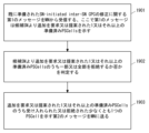
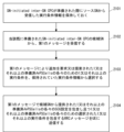
- FIG. 3 is a diagram illustrating a configuration example of a RAN node according to an embodiment. It is a flowchart which shows an example of operation of the RAN node (i.e., MN) according to the embodiment. It is a flowchart which shows an example of operation of the RAN node (i.e., MN) according to the embodiment. It is a flowchart which shows an example of operation of the RAN node (i.e., MN) according to the embodiment.
- FIG. 2 is a sequence diagram illustrating an example of signaling regarding inter-SN CPC (or conditional SN change) according to the embodiment.
- FIG. 3 is a diagram illustrating an example of the format of an S-NODE MODIFICATION REQUIRED message according to the embodiment.
- FIG. 3 is a diagram illustrating an example of a format of a CG-CandidateList message according to an embodiment. It is a flowchart which shows an example of operation of the RAN node (i.e., MN) according to the embodiment.
- FIG. 2 is a flowchart illustrating an example of the operation of a RAN node (i.e., MN) according to the embodiment.
- FIG. 2 is a sequence diagram illustrating an example of signaling regarding SN-initiated inter-SN CPC (or conditional SN change) according to the embodiment. It is a flowchart which shows an example of operation of the RAN node (i.e., MN) according to the embodiment. It is a flowchart which shows an example of operation of the RAN node (i.e., MN) according to the embodiment. It is a flowchart which shows an example of operation of the RAN node (i.e., MN) according to the embodiment.
- FIG. 3 is a diagram illustrating an example of the format of an S-NODE MODIFICATION CONFIRM message according to the embodiment.
- FIG. 3 is a diagram illustrating an example of the format of an S-NODE MODIFICATION CONFIRM message according to the embodiment.
- FIG. 3 is a diagram illustrating an example of the format of an S-NODE MODIFICATION CONFIRM message according to the embodiment. It is a flowchart which shows an example of operation of a RAN node (i.e., source SN) concerning an embodiment. It is a flowchart which shows an example of operation of a RAN node (i.e., source SN) concerning an embodiment.
- FIG. 3 is a diagram illustrating an example of the format of an S-NODE MODIFICATION REQUEST ACKNOWLEDGE message according to the embodiment.
- FIG. 2 is a flowchart illustrating an example of the operation of a RAN node (i.e., MN) according to the embodiment.
- FIG. FIG. 2 is a block diagram illustrating a configuration example of a RAN node according to an embodiment.
- FIG. 2 is a block diagram illustrating a configuration example of a UE according to an embodiment.
- LTE Long Term Evolution
- 5G system 5th generation mobile communication system
- LTE Long Term Evolution
- LTE-Advanced 5th generation mobile communication system
- if means “when,” “at or around the time,” and “after,” depending on the context. "after”, “upon”, “in response to determining", “in accordance with a determination", or “detecting” may be interpreted to mean “in response to detecting”. These expressions may be interpreted to have the same meaning, depending on the context.
- FIG. 1 shows a configuration example of a wireless communication system according to a plurality of embodiments.
- the wireless communication system includes RAN node 1, RAN node 2, RAN node 4, and UE3.
- Each element (network function) shown in Figure 1 can be implemented, for example, as a network element on dedicated hardware, as a software instance running on dedicated hardware, or as an application platform. It can be implemented as an instantiated virtualization function.
- the RAN node 1 may be a Central Unit (e.g., eNB-CU, or gNB-CU) in a cloud RAN (C-RAN) deployment, or a CU and one or more Distributed Units (e.g., eNB -DUs or gNB-DUs). C-RAN is also called CU/DU split. Furthermore, the CU may include a Control Plane (CP) Unit (e.g. gNB-CU-CP) and one or more User Plane (UP) Units (e.g. gNB-CU-UP). Therefore, the RAN node 1 may be a CU-CP or a combination of a CU-CP and a CU-UP.
- CP Control Plane
- UP User Plane
- each of RAN nodes 2 and 4 may be a CU or a combination of a CU and one or more DUs.
- Each of RAN nodes 2 and 4 may be a CU-CP or a combination of CU-CP and CU-UP.
- Each of the RAN nodes 1, 2, and 4 may be an Evolved Universal Terrestrial Radio Access Network (EUTRAN) node or a Next generation Radio Access Network (NG-RAN) node.
- the EUTRAN node may be an eNB or en-gNB.
- the NG-RAN node may be a gNB or ng-eNB.
- en-gNB is a node that provides NR user plane and control plane protocol termination to the UE and operates as an SN for E-UTRA-NR Dual Connectivity (EN-DC).
- ng-eNB is a node that provides E-UTRA user plane and control plane protocol termination to the UE and is connected to the 5GC via the NG interface.
- the Radio Access Technology (RAT) of RAN node 1 may be different from that of RAN nodes 2 and 4.
- RAT Radio Access Technology
- RAN node 1 and RAN node 2 communicate with each other via an inter-node interface (i.e., X2 interface or Xn interface) 103.
- RAN node 1 and RAN node 2 operate as MN and SN of dual connectivity, respectively.
- the RAN node 1 and the RAN node 4 communicate with each other via an inter-node interface (i.e., X2 interface or Xn interface) 105.
- RAN node 1 and RAN node 4 can operate as the MN and SN of the DC, respectively.
- An inter-node interface (i.e., X2 interface or Xn interface) 106 may be set between the RAN node 2 and the RAN node 4.
- RAN nodes 1, 2, and 4 and UE3 support inter-SN CPC from the SCG provided by RAN node 2 to the SCG provided by RAN node 4. Therefore, in the following, RAN node 1 may be referred to as MN1, RAN node 2 may be referred to as source SN (S-SN) 2, RAN node 4 may be referred to as target SN (T-SN) 4, candidate SN 4, Alternatively, it may be called target candidate SN4. Inter-SN CPC may be referred to as conditional SN change.
- Inter-SN CPC is an inter-SN PSCell change procedure (or SN change procedure) that is executed only when one or more CPC execution conditions are met or satisfied.
- the UE3 maintains the connection with the source SN2 and the source SCG, and starts evaluating the execution conditions set by the instruction. Then, the UE2 starts accessing the target candidate SN4 and the selected candidate PSCell in response to the execution condition being satisfied.
- the Inter-SN CPC can be initiated by MN1 or source SN2.
- the inter-SN CPC initiated by MN1 is called MN initiated inter-SN CPC.
- the inter-SN CPC initiated by source SN2 is called SN initiated inter-SN CPC.
- MN initiated inter-SN CPC MN1 generates CPC execution conditions.
- SN initiated inter-SN CPC the source SN2 generates CPC execution conditions and sends them to MN1.
- target candidate SN4 In both cases of MN-initiated inter-SN CPC and SN-initiated inter-SN CPC, target candidate SN4 generates the SCG configuration and sends it to the MN.
- the MN1 transmits the CPC configuration (e.g., ConditionalReconfiguration IE) including the CPC execution conditions and the SCG configuration to the UE3 via an RRC (Connection) Reconfiguration message.
- CPC configuration e.g., ConditionalReconfiguration IE
- RRC Connection
- multiple candidate cells i.e., candidate PSCells
- the UE3 configures one or more candidate PSCells (i.e., one or more SCG configurations) prepared by one or more candidate SNs and one or more SCG configurations associated with these.
- Further CPC execution conditions are received from MN1. More specifically, the configuration of each candidate PSCell is included in the information element (e.g., condRRCReconfig) of the RRC message of MN1, and the configuration of one or more candidate PSCells and the associated CPC execution conditions are generated by MN1. Included in conditional mobility configuration information (e.g., conditionalReconfiguration IE).
- conditional mobility configuration information e.g., conditionalReconfiguration IE
- the settings (i.e., SCG settings) of each candidate PSCell are generated by the candidate SN (e.g., candidate SN4) that provides (or has prepared) this candidate PSCell.
- the configuration of each candidate PSCell includes at least configuration information for the candidate PSCell.
- the configuration of each candidate PSCell may further include configuration information for one or more SCells that is attached to the candidate PSCell (that is, configured together with or associated with the candidate PSCell).
- the configuration or SCG configuration of each candidate PSCell may be a radio bearer (RB) configuration, a cell group (CG) configuration, or an SCG radio resource configuration, or any combination thereof.
- the configuration or SCG configuration of each candidate PSCell may be an SN RRC Reconfiguration message generated by a candidate SN (e.g., candidate SN4) that provides (or has prepared) this candidate PSCell.
- a candidate SN e.g., candidate SN4
- Part or all of the configuration of one or more candidate PSCells is included in the CPC configuration sent from MN1 to UE3.
- the CPC configuration of the Inter-SN CPC includes a list of one or more MN RRC Reconfiguration messages and associated execution conditions.
- Each MN RRC Reconfiguration message includes the candidate PSCell configuration or SCG configuration (e.g., one or any combination of RB configuration, CG configuration, SCG radio resource configuration, and SN RRC Reconfiguration message) received from the candidate SN. .
- the CPC execution condition is generated by MN1 in the case of MN-initiated inter-SN CPC, and generated by the source SN2 in the case of SN-initiated inter-SN CPC.
- a CPC execution condition may be comprised of one or more trigger conditions.
- the conditions or criteria that trigger a CPC event may be similar to those for measurement reporting events, such as CondEvent B1, CondEvent A3, CondEvent A4, or CondEvent A5.
- CondEvent B1 is “Conditional reconfiguration candidate becomes better than absolute threshold.”
- CondEvent A3 is “Conditional reconfiguration candidate becomes amount of offset better than PCell/PSCell”.
- CondEvent A4 is “Conditional reconfiguration candidate becomes better than absolute threshold.”
- CondEvent A5 is “PCell/PSCell becomes worse than absolute threshold1 AND Conditional reconfiguration candidate becomes better than another absolute threshold2”.
- UE3 evaluates CPC execution conditions. If the execution conditions for one candidate PSCell are met, the UE 3 configures the PSCell settings or SCG settings (e.g., RB settings, CG configuration, SCG radio resource configuration, and SN RRC Reconfiguration message, or any combination thereof). If a bearer requiring SCG radio resources is configured, UE3 performs synchronization to the selected PSCell. If the execution conditions for two or more candidate PSCells are met, the UE 3 may select one of the candidate PSCells and perform the operations described above.
- SCG settings e.g., RB settings, CG configuration, SCG radio resource configuration, and SN RRC Reconfiguration message, or any combination thereof.
- UE3 performs synchronization to the selected PSCell.
- UE3 communicates with MN1 and S-SN2 via air interfaces 101 and 102, and performs dual connectivity of MCG provided by MN1 and SCG provided by S-SN2. Also, by performing inter-SN CPC, UE3 communicates with MN1 and T-SN4 via air interfaces 101 and 104, and provides dual connectivity of MCG provided by MN1 and SCG provided by T-SN4. conduct.
- MN1 may be a master eNB (in EN-DC), a master ng-eNB (in NGEN-DC), or a master gNB (in NR-DC and NE-DC).
- each of S-SN2 and T-SN4 is a It may be.
- UE3 is connected to the eNB that operates as MN1, and also to the en-gNB that operates as S-SN2 or T-SN4.
- UE3 is connected to ng-eNB that operates as MN1, and also connected to gNB that operates as S-SN2 or T-SN4.
- the NE-DC is connected to the gNB that operates as MN1, and also to the ng-eNB that operates as S-SN2 or T-SN4.
- UE3 is connected to one gNB (or gNB-DU) that operates as MN1 and to another gNB (or gNB-DU) that operates as S-SN2 or T-SN4. .
- the MCG is a group of serving cells associated with (or provided with) MN1, including an SpCell (i.e., Primary Cell (PCell)) and optionally one or more secondary cells ( Secondary Cells (SCells)).
- SCG is a group of serving cells associated with (or provided with) S-SN2 or T-SN4, including a Primary SCG Cell (PSCell) and optionally one or more serving cells.
- PSCell Primary SCG Cell
- SCells Primary SCG Cell
- SCells Primary SCG Cell
- PSCell is a Special Cell (SpCell) of SCG and supports Physical Uplink Control Channel (PUCCH) transmission and contention-based Random Access.
- PSCell may be an abbreviation for Primary SCell.
- the term “primary SCG cell” and its abbreviation “PSCell” are included in a cell group provided by a dual connectivity SN and have an uplink component carrier and an uplink control channel (e.g. PUCCH) means a cell for which resources are configured.
- PUCCH uplink control channel
- the term “primary SCG cell” and its abbreviation “PSCell” refer to the term “primary SCG cell” and its abbreviation “PSCell” used by SNs that support 5G NR (e.g. en-gNB in EN-DC, gNB in NGEN-DC, or gNB in NR-DC). It may refer to the Primary SCG Cell of a cell group provided by an SN that supports E-UTRA (e.g. eNB in LTE DC, or ng-eNB in NE-DC). You may.
- FIG. 2 shows another example configuration of a wireless communication system according to multiple embodiments.
- the wireless communication system includes RAN node 1, RAN node 4, and UE3.
- Each element (network function) shown in Figure 2 may be, for example, a network element on dedicated hardware, a software instance running on dedicated hardware, or a virtualized function instantiated on an application platform. It can be implemented as
- the RAN node 1, RAN node 4, and UE 3 in the example of FIG. 2 may have configurations and functions similar to those in the example of FIG. 1. Specifically, the RAN node 1 and the RAN node 4 communicate with each other via an inter-node interface (i.e., X2 interface or Xn interface) 105. RAN node 1 and RAN node 4 operate as dual connectivity MN and SN, respectively. UE3 communicates with MN1 and SN4 via air interfaces 101 and 104, and performs dual connectivity of MCG and SCG. This dual connectivity may be Multi-Radio Dual Connectivity (MR-DC).
- MR-DC Multi-Radio Dual Connectivity
- RAN nodes 1 and 4 and UE3 support conditional PSCell addition (CPA) that adds the SCG provided by RAN node 4 for UE3. Therefore, below, RAN node 1 may be referred to as MN1, and RAN node 4 may be referred to as candidate SN4. CPA may also be referred to as conditional SN addition.
- CPA (or conditional SN addition) is a PSCell addition procedure (or SN addition procedure) that is executed only when the CPA execution conditions are met.
- CPA conditional SN addition
- MN1 generates CPA execution conditions.
- Candidate SN4 generates an SCG configuration and sends it to MN1.
- the MN1 sends the CPA configuration (e.g., ConditionalReconfiguration IE), which includes both the CPA execution conditions and the SCG configuration, to the UE3 via an RRC (Connection) Reconfiguration message.
- CPA configuration e.g., ConditionalReconfiguration IE
- multiple candidate PSCells provided by multiple candidate SN4 may be prepared for CPA.
- the UE 3 configures one or more candidate PSCells (i.e., one or more SCG configurations) prepared by one or more candidate SNs and one or more associated SCG configurations.
- conditional mobility configuration information e.g., conditionalReconfiguration IE).
- the settings for each candidate PSCell are generated by the candidate SN (e.g., candidate SN4) that provides (or prepares) this candidate PSCell.
- the configuration of each candidate PSCell includes at least configuration information for the candidate PSCell.
- the configuration of each candidate PSCell may further include configuration information for one or more SCells that is attached to the candidate PSCell (that is, configured together with or associated with the candidate PSCell).
- the configuration or SCG configuration of each candidate PSCell may be one or any combination of RB configuration, CG configuration, and SCG radio resource configuration.
- the configuration or SCG configuration of each candidate PSCell may be an SN RRC Reconfiguration message generated by a candidate SN (e.g., candidate SN4) that provides (or has prepared) this candidate PSCell.
- a candidate SN e.g., candidate SN4
- Part or all of the configuration of one or more candidate PSCells is included in the CPA configuration sent from MN1 to UE3.
- a CPA configuration includes a list of one or more MN RRC Reconfiguration messages and associated execution conditions.
- Each MN RRC Reconfiguration message includes the candidate PSCell configuration or SCG configuration (e.g., one or any combination of RB configuration, CG configuration, SCG radio resource configuration, and SN RRC Reconfiguration message) received from the candidate SN. .
- the CPA execution conditions are generated by MN1.
- a CPA execution condition may be composed of one or more trigger conditions.
- the conditions or criteria that trigger a CPA event may be similar to those for measurement reporting events, such as CondEvent A3, CondEvent A4, or CondEvent A5.
- UE3 evaluates the CPA execution conditions. When the execution condition of one candidate PSCell is satisfied, the UE 3 configures the PSCell settings (i.e., CG settings, SCG settings, SCG radio resource configuration or SN RRC Reconfiguration message). If a bearer requiring SCG radio resources is configured, UE3 performs synchronization to the selected PSCell. If the execution conditions for two or more candidate PSCells are met, the UE 3 may select one of the candidate PSCells and perform the operations described above.
- the PSCell settings i.e., CG settings, SCG settings, SCG radio resource configuration or SN RRC Reconfiguration message. If a bearer requiring SCG radio resources is configured,
- One or more of RAN nodes 1, 2, and 4 may have the configuration shown in FIG. 3.
- Each element (network function) shown in FIG. 3 may be, for example, a network element on dedicated hardware, a software instance running on dedicated hardware, or a virtualized function instantiated on an application platform. It can be implemented as One or more of RAN nodes 1, 2, and 4 may include, but are not limited to, a CU 31 and one or more DUs 32 as shown in FIG. 3.
- An interface 3301 connects the CU 31 and each DU 32.
- the UE 3 is connected to at least one DU 32 via at least one air interface 302 .
- the CU 31 may be a logical node that hosts the gNB's RRC, Service Data Adaptation Protocol (SDAP), and Packet Data Convergence Protocol (PDCP) protocols (or the gNB's RRC and PDCP protocols).
- the DU 32 may be a logical node that hosts the Radio Link Control (RLC), Medium Access Control (MAC), and Physical (PHY) layers of the gNB. If the CU 31 is a gNB-CU and the DUs 32 are gNB-DUs, the interface 301 may be an F1 interface.
- CU31 may include CU-CP and CU-UP.
- Conditional mobility is a general term that refers to one or more of Conditional Handover (CHO), CPA, intra-SN CPC (or conditional SN modification), and inter-SN CPC (or conditional SN modification).
- CHO Conditional Handover
- CPA CPA
- intra-SN CPC or conditional SN modification
- inter-SN CPC or conditional SN modification
- MN RRC message MN RRC (Connection) Reconfiguration message
- SN RRC message SN RRC Reconfiguration message
- SN RRC Reconfiguration message SN RRC Reconfiguration message
- Some embodiments described below provide improvements in conditional mobility. Some embodiments provide improvements to the procedure by which candidate SN4 adds one or more new prepared PSCells in a prepared CPA or Inter-SN CPC. This operation or procedure may be referred to as, for example and without limitation, candidate SN triggered prepared cell addition.
- This embodiment provides improvements to inter-SN CPC for candidate SN triggered prepared cell addition. Specifically, the present embodiment relates to clarification of various procedures regarding candidate SN triggered prepared cell addition when multiple inter-SN CPCs are prepared in parallel.
- the configuration example of the wireless communication system according to this embodiment may be the same as the example shown in FIG. 1.
- FIG. 4 shows an example of the operation of MN1.
- Figure 4 is directed to the case where a first inter-SN CPC initiated by MN1 and a second inter-SN CPC initiated by source SN2 are configured or prepared in parallel to one target candidate SN4. ing.
- MN1 receives a first message from candidate SN4.
- candidate SN4 is a candidate SN for the first inter-SN CPC (i.e., MN-initiated inter-SN CPC) and a candidate for the second inter-SN CPC (i.e., SN-initiated inter-SN CPC) Also SN.
- the first message may be a message sent by candidate SN4 to request or propose modification of SN resources for UE3.
- the first message may be a message requesting or suggesting a modification or update of the prepared CPA or CPC information.
- the first message may be an S-NODE MODIFICATION REQUIRED message.
- the first message is an information element that indicates a request or suggestion to update the prepared CPA or CPC information (e.g., Conditional PSCell Addition or Change (CPAC)Information Required IE, Prepared Cell Addition IE, Prepared CPC Update IE) May include.
- CPAC Conditional PSCell Addition or Change
- the prepared CPA or CPC information is acknowledged by the candidate SN4 in the previous SN addition procedure and is sent via the S-NODE ADDITION REQUEST ACKNOWLEDGE message (e.g., Conditional PSCell Addition Information Acknowledge IE in the message).
- the CPA or CPC information includes a list of one or more prepared PSCells prepared by the candidate SN4.
- the list of prepared PSCells may be referred to as a prepared PSCell list or a prepared candidate PSCell list.
- the first message indicates or includes an updated list of one or more prepared PSCells.
- the updated list may be called an updated prepared PSCell list or an updated prepared candidate PSCell list.
- the updated list may indicate the addition of at least one new prepared PSCell or the cancellation (or release) of at least one existing prepared PSCell, or both.
- the updated list may be a list of prepared PSCells that has been updated by adding at least one new prepared PSCell, canceling at least one existing prepared PSCell, or both.
- the updated list may indicate an updated full list of prepared PSCells.
- the updated list may include not only newly added prepared PSCell(s) but also existing prepared PSCell(s) that have not been cancelled.
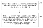
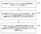
- MN1 determines whether the updated list of one or more prepared PSCells indicated by the first message relates to a first inter-SN CPC or a second inter-SN CPC. . In other words, MN1 determines whether the modification or update of the CPA or CPC information indicated in the first message relates to the first inter-SN CPC or the second inter-SN CPC.
- MN1 may operate as shown in FIG. Step 501 is similar to step 401 in FIG. In step 502, MN1 determines whether the updated list relates to the first and second inter-SN CPCs (a) based on the updated list itself; or (b) based on the first message. or (c) both.
- MN1 determines that one or more prepared PSCells included in the updated list received from candidate SN4 are the first suggested PSCells for the first inter-SN CPC. It may be checked whether it is included in the list or the second proposed PSCell list for the second inter-SN CPC.
- the first proposed PSCell list is a list of candidate PSCells proposed by MN1 for MN-initiated inter-SN CPC.
- the second proposed PSCell list is the list of candidate PSCells proposed by the source SN2 for the SN-initiated inter-SN CPC.
- MN1 determines that the updated list received from candidate SN4 was initiated by MN1. may be determined (or concluded) regarding the first inter-SN CPC. Conversely, if the updated list contains PSCells that are included in the second proposed PSCell list but not included in the first proposed PSCell list, then MN1 assumes that the updated list received from candidate SN4 is It may be determined (or concluded) that the second inter-SN CPC is initiated by source SN2.
- MN1 may check the inter-node RRC message included in the first message received from candidate SN4. If MN1 cannot determine from the updated list itself whether the updated list relates to the first or second inter-SN CPC, MN1 considers the inter-node RRC message in the first message. You can.
- an inter-node RRC message is an RRC message sent between RAN nodes via an inter-node interface such as an X2 interface or an Xn interface.
- the inter-node RRC message in the first message is sent from candidate SN4 to MN1.
- the inter-node RRC message in the first message may be the CG-CandidateList message defined in Chapter 11.2.2 of Non-Patent Document 3.
- MN1 may check the list of ready PSCells to be released (e.g., cg-CandidateToReleaseList included in the CG-CandidateList message) indicated by the inter-node RRC message in the first message. . MN1 then determines whether the updated list relates to the first or second inter-SN The determination may be made based on which of the inter-SN CPCs. Specifically, if one or more cell identifiers included in the list of prepared PSCells to be released are related to the first inter-SN CPC, MN1 also updates the prepared PSCell list to the first inter-SN CPC. You may decide (or conclude) that the SN CPC is relevant.
- the list of ready PSCells to be released e.g., cg-CandidateToReleaseList included in the CG-CandidateList message
- MN1 determines whether the updated list relates to the first or second inter-SN The determination may be made based on which of the inter-SN CPC
- MN1 also uses the updated prepared PSCell list to refer to the second inter-SN CPC. may decide (or conclude) that
- the updated list may not be possible to determine whether the updated list relates to the first or second inter-SN CPC using the updated list itself, the inter-node RRC message, or both. For example, there may be a case where all PSCell(s) included in the updated prepared PSCell list are commonly included in both the first proposed PSCell list and the second proposed PSCell list. In addition, all cell identifier(s) included in the list of ready PSCells to be released indicated by the inter-node RRC message in the first message are present in both the first and second inter-SN CPCs. A case may arise where PSCell(s) are commonly prepared for In such a case, MN1 may autonomously determine (or conclude) whether the updated list relates to the first or second inter-SN CPC.
- the MN1 may determine that the updated list pertains to the one of the first and second inter-SN CPCs that has a larger maximum number of PSCells that the candidate SN4 can prepare. Conversely, the MN1 may decide that the updated list relates to the one of the first and second inter-SN CPCs that has a smaller maximum number of PSCells that the candidate SN4 can prepare. Alternatively, MN1 may finalize that the updated list pertains to the one of the first and second inter-SN CPCs that has a greater margin up to the maximum number of PSCells that candidate SN4 can prepare.
- MN1 may finalize that the updated list pertains to the one of the first and second inter-SN CPCs that has a smaller margin up to the maximum number of PSCells that candidate SN4 can prepare.
- the maximum number of PSCells that candidate SN4 can prepare is determined by the node initiating the inter-SN CPC, i.e. by MN1 in case of MN-initiated inter-SN CPC and by source SN2 in case of SN-initiated inter-SN CPC. Ru.
- the maximum number of PSCells that the candidate SN4 can prepare can be sent from the MN1 to the target candidate SN4 via the S-NODE ADDITION REQUEST message when preparing the inter-SN CPC.
- the maximum number of PSCells that candidate SN4 can prepare can be sent from source SN2 to MN1 via an S-NODE CHANGE REQUIRED message.
- the maximum number of PSCells that candidate SN4 can prepare may be included in the “Maximum Number of PSCells To Prepare” IE of the S-NODE ADDITION REQUEST message (and S-NODE CHANGE REQUIRED message).
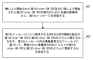
- MN1 may operate as shown in FIG. 6 instead of the operation in FIG. Step 601 is similar to step 401 in FIG.
- MN1 sends a first message that explicitly or implicitly indicates whether the modification of the CPA or CPC information requested by the first message relates to the first or second inter-SN CPC.
- the MN1 determines whether the updated prepared PSCell list relates to the first inter-SN CPC or the second inter-SN CPC according to the content of the information element or field.
- the first message (e.g., S-NODE MODIFICATION REQUIRED message) indicates whether the modification of the CPA or CPC information requested by the first message is in the first or second inter-SN CPC. It is enhanced to include an information element or field indicating whether the
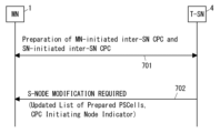
- FIG. 7 shows an example of the operation of MN1 and target candidate SN4.
- MN1 and candidate SN4 prepare first and second inter-SN CPCs, both MN-initiated inter-SN CPC and SN-initiated inter-SN CPC.
- candidate SN4 sends an S-NODE MODIFICATION REQUIRED message to MN1 to update the CPA or CPC information of either the first and second inter-SN CPCs.
- the S-NODE MODIFICATION REQUIRED message includes (or indicates) an updated list of prepared PSCell(s).
- the S-NODE MODIFICATION REQUIRED message may include an information element or Contains fields.
- the information element or field may specify whether the node that initiated the inter-SN CPC is the MN (e.g., MN1) or the source SN (e.g., source SN2).
- the name of the information element or field may be, but is not limited to, "CPC Initiating Node", for example.
- the name of the information element or field may be "CPC Source Node", meaning the node that starts the inter-SN CPC procedure.
- the information element or field may be an X2AP or XnAP information element within the first message.
- the information element or field may be a field in an inter-node RRC message (e.g., CG-CandidateList message) included in the first message.
- FIG. 8 shows an example of the format of the S-NODE MODIFICATION REQUIRED message.
- a new information element “CPC Initiating Node” is included in the Candidate PSCell List IE.
- the information element may be of enumerated type and may indicate MN or SN.
- the format of FIG. 8 can be modified as appropriate.
- the CPC Initiating Node IE may be included within the CPAC Information Required IE in parallel with the Candidate PSCell List IE.
- FIG. 9 shows an example of the format of the CG-CandidateList message, which is one of the inter-node RRC messages.
- the CG-CandidateList message can be included in the S-NG-RAN node to M-NG-RAN node Container IE in the S-NODE MODIFICATION REQUIRED message sent from target candidate SN4 to MN1.
- the CG-CandidateList message includes a CPCinitiatingNode information element or field 902 within a CG-CandidateInfo information element or field 901.
- Information element or field 902 may be of enumerated type and may indicate MN or SN.
- the format of FIG. 9 can be modified as appropriate.
- CPCinitiatingNode information element or field 902 may be included within CG-CandidateInfoId information element or field 903.
- the CPCinitiatingNode information element or field 902 may be included within the CG-CandidateList information element or field 904 in parallel with cg-CandidateToAddModList or cg-CandidateToReleaseList or both.
- MN1 and target candidate SN4 can provide the following advantages. That is, when both MN-initiated inter-SN CPC and SN-initiated inter-SN CPC are prepared, MN1 updates the prepared PSCell list proposed or requested by candidate SN4 to two inter-SN CPCs. It is possible to determine (or conclude) which of the SN CPCs is relevant.
- This embodiment provides improvements to inter-SN CPC for candidate SN triggered prepared cell addition.
- the present embodiment relates to the clarification of various procedures regarding candidate SN triggered prepared cell addition when an SN-initiated inter-SN CPC is being prepared.
- inter-SN CPC when inter-SN CPC is prepared, for example, a state in which MN1 has already completed sending an RRC message (eg RRC (Connection) Reconfiguration) for inter-SN CPC to UE3, or This means a state in which the UE 3 receives an RRC message for inter-SN CPC and starts operations necessary for inter-SN CPC (eg, evaluation of candidate PSCells).
- RRC message eg RRC (Connection) Reconfiguration
- the configuration example of the wireless communication system according to this embodiment may be the same as the example shown in FIG. 1.
- FIG. 10 shows an example of the operation of MN1.
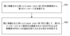
- MN1 receives a first message from candidate SN4 of the already prepared SN-initiated inter-SN CPC. Similar to that described in the first embodiment, the first message may be a message sent by the candidate SN4 to request or propose modification of SN resources for the UE3. The first message may be a message requesting or suggesting an update of the prepared CPA or CPC information. The first message may be an S-NODE MODIFICATION REQUIRED message.
- the first message may indicate (or may include) an updated list of one or more prepared PSCells.
- the updated list may be referred to as an updated prepared PSCell list.
- the updated list may indicate the addition of at least one new prepared PSCell or the cancellation (or release) of at least one existing prepared PSCell, or both.
- the updated list may be a list of prepared PSCells that has been updated by adding at least one new prepared PSCell, canceling at least one existing prepared PSCell, or both.
- the updated list may indicate an updated full list of prepared PSCells.
- the updated list may include not only newly added prepared PSCell(s) but also existing prepared PSCell(s) that have not been cancelled.
- step 1002 the MN1 determines whether to accept the addition of one or more prepared PSCells requested or proposed by the first message with respect to the already prepared SN-initiated inter-SN CPC.
- MN1 informs source SN2, which initiated the SN-initiated inter-SN CPC, of whether to accept one or more prepared PSCells requested or proposed to be added by candidate SN4. There is no need to inquire. This can contribute to quickly sending the added prepared PSCell settings (SCG settings) and related execution conditions to the UE3.
- MN1 decides whether to accept or reject the entire update of the prepared PSCell list. In other words, MN1 may not support accepting (or rejecting) only some of the additions of new prepared PSCells resulting in an updated prepared PSCell list. Similarly, MN1 may not support accepting (or rejecting) only some of the cancellations of one or more existing prepared PSCells resulting in an updated prepared PSCell list.
- MN1 determines whether to reject some or all of the prepared PSCells requested or proposed to be added by the first message. MN1 may determine whether to reject some or all of the cancellations of existing prepared PSCells requested or proposed by the first message. MN1 may reject only one of the addition of new prepared PSCell(s) and the cancellation of existing prepared PSCell(s) requested or proposed by the first message.
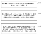
- FIG. 11 shows an example of the operation of MN1. Steps 1101 and 1102 are similar to steps 1001 and 1002 in FIG. In step 1103, if some or all of the one or more prepared PSCells requested or proposed to be added by the first message are accepted, the accepted at least one additional prepared PSCell is added to source SN2. Notify via message 2.
- the second message may be an S-NODE MODIFICATION REQUEST message.
- FIG. 12 shows an example of the operation of MN1.
- the operation of FIG. 12 may be performed by MN1 along with the operation of FIG. 11.
- Steps 1201 and 1202 are similar to steps 1001 and 1002 in FIG.
- MN1 sends a third message to candidate SN4 indicating the accepted or rejected at least one PSCell of the one or more prepared PSCells requested or suggested for addition by the first message. send.
- the third message may indicate the entire list of one or more prepared PSCells that have been accepted.
- the third message may be an S-NODE MODIFICATION CONFIRM message or an S-NODE MODIFICATION REFUSE message.
- the S-NODE MODIFICATION REFUSE message may indicate a new Cause value.
- the new cause value may be, for example, but not limited to, “CPA-CPC resources partially (NOT) accepted”.
- the S-NODE MODIFICATION REFUSE message may include the M-NG-RAN node to S-NG-RAN node Container IE.
- the M-NG-RAN node to S-NG-RAN node Container IE contains the CG-ConfigInfo message.
- the CG-ConfigInfo message is an inter-node RRC message sent from MN1 to candidate SN4 and may indicate the entire list of one or more prepared PSCells accepted by MN1.
- a fourth message indicating the message may be sent to candidate SN4.
- the fourth message may be an S-NODE MODIFICATION REFUSE message.
- the S-NODE MODIFICATION REFUSE message may indicate a new Cause value.
- the new cause value may be, for example and without limitation, "CPA-CPC resources NOT accepted” or "CPA-CPC resources NOT updated”.
- the MN1 may retain the execution condition information received from the source SN2 when the SN-initiated inter-SN CPC was prepared. Then, MN1 selects one or more execution conditions for each of the one or more prepared PSCells requested or proposed to be added by the first message from the held execution condition information. (or read out or taken out). Note that if MN1 accepts only a portion of the one or more prepared PSCells requested or proposed for addition, MN1 may retrieve the execution conditions of the accepted prepared PSCell(s). MN1 then includes the SCG settings for each of the prepared PSCell(s) provided by candidate SN4 in the first message and selects one or more SCG settings for each of these prepared PSCell(s).
- the RRC message may be transmitted to the UE3.
- the RRC message may be a MN RRC (Connection) Reconfiguration message.
- MN1 associates with the added prepared PSCell(s).
- SCG settings execution conditions
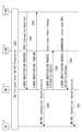
- FIG. 13 shows an example of signaling regarding SN-initiated inter-SN CPC.
- an inter-SN CPC initiated by source SN2 is prepared.
- Step 1302 corresponds to step 1001 in FIG. 10, step 1101 in FIG. 11, and step 1201 in FIG. That is, target candidate SN4 sends a first message (here, an S-NODE MODIFICATION REQUIRED message) to MN1.
- the S-NODE MODIFICATION REQUIRED message includes the CPAC Information Required IE.
- the CPAC Information Required IE indicates the updated prepared PSCell list for the SN-initiated inter-SN CPC prepared in step 1301. MN1 determines whether to accept the updated prepared PSCell list for SN-initiated inter-SN CPC.
- MN1 accepts some or all of the one or more prepared PSCells proposed or requested in the updated prepared PSCell list.
- Step 1303 corresponds to step 1203 in FIG. Specifically, MN1 sends an S-NODE MODIFICATION CONFIRM message to candidate SN4.
- the S-NODE MODIFICATION CONFIRM message indicates at least one PSCell that has been accepted among the one or more prepared PSCells whose addition was requested or proposed by the S-NODE MODIFICATION REQUIRED message in step 1302.
- MN1 transmits a MN RRC (Connection) Reconfiguration message to UE3.
- the RRC message includes the configuration (or SCG configuration) of each prepared PSCell(s) provided by the candidate SN4 in the S-NODE MODIFICATION REQUIRED message of step 1302.
- each prepared PSCell configuration or SCG configuration may be referred to as an SCG radio resource configuration.
- the settings of each prepared PSCell or SCG settings may be included in the CG-CandidateList message included in the S-NG-RAN node to M-NG-RAN node Container IE in the S-NODE MODIFICATION REQUIRED message in step 1302. good.
- each prepared PSCell or the SCG configuration may be included in a corresponding scg-CellGroupConfig field of one or more CG-Config IEs included in the CG-CandidateList message.
- Each prepared PSCell configuration or SCG configuration may be an SN RRC Reconfiguration message or one or more IEs (e.g., CellGroupConfig IE) included in the SN RRC Reconfiguration message.
- CellGroupConfig IE is used to configure the SCG.
- the RRC message includes selected one or more execution conditions for each of these prepared PSCell(s). Note that the bearer settings associated with each prepared PSCell may also be included in the CG-CandidateList message.
- the bearer configuration associated with each prepared PSCell may be included in the corresponding scg-RB-Config field of one or more CG-Config IEs included in the CG-CandidateList message.
- the MN RRC message may include bearer settings associated with each prepared PSCell.
- Step 1305 corresponds to step 1103 in FIG. 11. That is, MN1 informs source SN2 of the accepted at least one additional prepared PSCell, for example via an S-NODE MODIFICATION REQUEST message.
- the message may indicate the updated complete list of prepared PSCells.
- the complete list may be indicated by the Conditional PSCell Change Information Update IE included in the S-NODE MODIFICATION REQUEST message.
- source SN2 may respond to MN1 with an S-NODE MODIFICATION REQUEST ACKNOWLEDGE message.
- Step 1306 may be omitted.
- source SN2 may provide MN1 with one or more CPC execution conditions for each of the additional prepared PSCell(s). These execution conditions may be indicated by a CG-Config message carried by the S-NG-RAN node to M-NG-RAN node Container IE included in the S-NODE MODIFICATION REQUEST ACKNOWLEDGE message.
- the CG-Config message is an inter-node RRC message sent from source SN2 to MN1.
- MN1 may send a MN RRC Reconfiguration message to UE3.
- the MN RRC Reconfiguration message may indicate a modification or update of one or more execution conditions of the prepared PSCell(s). If step 1306 is omitted, or if the S-NODE MODIFICATION REQUEST ACKNOWLEDGE message in step 1306 does not indicate updated CPC execution conditions, step 1307 may be omitted.
- step 1304 may be performed after step 1305 or after step 1306.
- step 1303 may be performed after step 1304, after step 1305, after step 1306, or after step 1307.
- step 1304 may be integrated with or replaced by step 1307.
- the procedure shown in FIG. 13 can provide the following advantages. As shown in FIG. 13, the sending of the MN RRC (Connection) Reconfiguration message from MN1 to UE3 (step 1304) is performed before or without querying the source SN2 (step 1305). This can contribute to quickly sending the added prepared PSCell settings (SCG settings) and related execution conditions to the UE3.
- MN RRC Connection
- This embodiment provides an improvement to inter-SN CPC or CPA for candidate SN triggered prepared cell addition.
- the configuration example of the wireless communication system according to this embodiment may be the same as the example shown in FIG. 1 or FIG. 2.
- FIG. 14 shows an example of the operation of MN1.
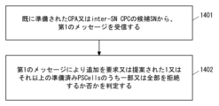
- MN1 receives a first message from an already prepared CPA or inter-SN CPC candidate SN4.
- the Inter-SN CPC may be an MN-initiated inter-SN CPC initiated by MN1 or an SN-initiated inter-SN CPC initiated by source SN2.
- the first message may be a message sent by the candidate SN4 to request or propose modification of SN resources for the UE3.
- the first message may be a message requesting or suggesting an update of the prepared CPA or CPC information.
- the first message may be an S-NODE MODIFICATION REQUIRED message.
- the first message may indicate (or may include) an updated list of one or more prepared PSCells.
- the updated list may be referred to as an updated prepared PSCell list.
- the updated list may indicate the addition of at least one new prepared PSCell or the cancellation (or release) of at least one existing prepared PSCell, or both.
- the updated list may be a list of prepared PSCells that has been updated by adding at least one new prepared PSCell, canceling at least one existing prepared PSCell, or both.
- the updated list may indicate an updated full list of prepared PSCells.
- the updated list may include not only newly added prepared PSCell(s) but also existing prepared PSCell(s) that have not been cancelled.
- MN1 determines whether to reject some or all of the one or more prepared PSCells requested or proposed to be added by the first message. In other words, MN1 supports rejecting the addition of new prepared PSCells resulting in an updated prepared PSCell list. In other words, MN1 supports accepting (or rejecting) only some of the additions of new prepared PSCells resulting in an updated prepared PSCell list.
- MN1 is allowed to partially or completely reject one or more prepared PSCells requested or proposed to be added by candidate SN4.
- Candidate PSCell(s) that were proposed to candidate SN4 when preparing the CPA or inter-SN CPC but were not prepared may no longer be suitable candidates for MN1 or for UE3 due to subsequent changes in circumstances.
- MN1 can reject prepared PSCell(s) that are no longer suitable. In other words, MN1 can refuse to add candidate PSCell(s) that are no longer suitable.
- FIG. 15 shows an example of the operation of MN1.
- Steps 1501 and 1502 are similar to steps 1401 and 1402 in FIG.
- MN1 sends a second message to candidate SN4 indicating the accepted or rejected at least one PSCell among the one or more prepared PSCells requested or suggested for addition by the first message. send.
- the second message may indicate the entire list of one or more prepared PSCells accepted by MN1.
- the second message may be an S-NODE MODIFICATION CONFIRM message or an S-NODE MODIFICATION REFUSE message.
- the S-NODE MODIFICATION REFUSE message may indicate a new Cause value.
- the new cause value may be, for example, but not limited to, “CPA-CPC resources partially (NOT) accepted”.
- the S-NODE MODIFICATION REFUSE message may include the M-NG-RAN node to S-NG-RAN node Container IE.
- the M-NG-RAN node to S-NG-RAN node Container IE contains the CG-ConfigInfo message.
- the CG-ConfigInfo message is an inter-node RRC message sent from MN1 to candidate SN4 and may indicate the entire list of one or more prepared PSCells accepted by MN1.
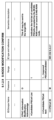
- the format of the S-NODE MODIFICATION CONFIRM message may be extended as shown in FIG. 16 or 17.
- the S-NODE MODIFICATION CONFIRM message includes either the complete list of one or more prepared PSCells accepted by MN1 or one or more newly added prepared PSCells accepted by MN1 ( s), including the newly defined XnAP IE.
- the name of the XnAP IE may be, but is not limited to, for example, CPAC Information Modification Acknowledge IE.
- the S-NODE MODIFICATION CONFIRM message includes a new XnAP IE that may include a CG-ConfigInfo message.
- the name of the XnAP IE may be, but is not limited to, Additional M-NG-RAN node to S-NG-RAN node Container IE, for example.
- This CG-ConfigInfo message is an inter-node RRC message sent from MN1 to candidate SN4, which may indicate the entire list of one or more prepared PSCells accepted by MN1, A list of one or more newly added prepared PSCell(s) may be indicated.
- a third message indicating the message may be sent to candidate SN4.
- the third message may be an S-NODE MODIFICATION REFUSE message.
- the S-NODE MODIFICATION REFUSE message may indicate a new Cause value.
- the new cause value may be, for example and without limitation, "CPA-CPC resources NOT accepted” or "CPA-CPC resources NOT updated”.
- This embodiment provides an improvement to SN-initiated inter-SN CPC for candidate SN triggered prepared cell addition.
- the configuration example of the wireless communication system according to this embodiment may be the same as the example shown in FIG. 1.
- FIG. 18 shows an example of the operation of the source SN2.
- the source SN2 receives from MN1 a first message regarding modification of an already prepared SN-initiated inter-SN CPC.
- the first message indicates one or more prepared PSCells requested or proposed to be added by candidate SN4.
- the first message may be a message sent by MN1 to request or suggest modification of SN resources for UE3.
- the first message may be a message requesting or suggesting modification or updating of CPA or CPC information.
- the first message may be an S-NODE MODIFICATION REQUEST message.
- the first message may indicate (or may include) an updated list of one or more prepared PSCells.
- the updated list may be referred to as an updated prepared PSCell list.
- the updated list may indicate the addition of at least one new prepared PSCell or the cancellation (or release) of at least one existing prepared PSCell, or both.
- the updated list may be a list of prepared PSCells that has been updated by adding at least one new prepared PSCell, canceling at least one existing prepared PSCell, or both.
- the updated list may indicate an updated full list of prepared PSCells.
- the updated list may include not only newly added prepared PSCell(s) but also existing prepared PSCell(s) that have not been cancelled.
- the source SN2 determines whether to reject some or all of the one or more prepared PSCells requested or proposed to be added by the candidate SN4. In other words, source SN2 supports rejecting the addition of new prepared PSCells resulting in an updated prepared PSCell list. In other words, the source SN2 supports accepting (or rejecting) only some of the additions of new prepared PSCells resulting in an updated prepared PSCell list.
- the source SN2 is allowed to partially or completely reject one or more prepared PSCells requested or proposed to be added by the candidate SN4.
- Candidate PSCell(s) that were proposed to candidate SN4 when preparing the SN-initiated inter-SN CPC but were not prepared may no longer be suitable candidates for source SN2 or for UE3 due to subsequent changes in circumstances. be.
- the source SN2 can reject prepared PSCell(s) that are no longer suitable.
- FIG. 19 shows an example of the operation of the source SN2. Steps 1901 and 1902 are similar to steps 1801 and 1802 in FIG. In step 1903, source SN2 sends a second message to MN1 indicating at least one accepted or rejected of the one or more prepared PSCells requested or proposed for addition.
- the second message may indicate a complete list of one or more prepared PSCells accepted by source SN2, or one or more newly added prepared PSCells accepted by source SN2. You may also show a list of The second message may be an S-NODE MODIFICATION REQUEST ACKNOWLEDGE message.
- the format of the S-NODE MODIFICATION REQUEST ACKNOWLEDGE message may be extended as shown in FIG. 20.
- the S-NODE MODIFICATION REQUEST ACKNOWLEDGE message includes a complete list of one or more prepared PSCells accepted by source SN2 or one or more newly added ready PSCells accepted by source SN2. Contains the newly defined XnAP IE to show the list of used PSCells.
- the name of the XnAP IE may be, but is not limited to, Conditional PSCell Change Information Update Acknowledge IE, for example.
- a third message may be sent to MN1 indicating.
- the third message may be an S-NODE MODIFICATION REQUEST REJECT message.
- the S-NODE MODIFICATION REQUEST REJECT message may indicate a new Cause value.
- the new cause value may be, for example and without limitation, "CPC resources NOT accepted” or "CPA-CPC resources NOT updated”.
- This embodiment provides an improvement to SN-initiated inter-SN CPC for candidate SN triggered prepared cell addition.
- the configuration example of the wireless communication system according to this embodiment may be the same as the example shown in FIG. 1.
- FIG. 21 shows an example of the operation of MN1.
- the MN1 retains the execution condition information received from the source SN2 when the SN-initiated inter-SN CPC was prepared.
- the execution condition information indicates one or more CPC execution conditions for each PSCell included in the candidate PSCell list proposed by the source SN2.
- MN1 receives a first message from candidate SN4 of the already prepared SN-initiated inter-SN CPC. Similar to that described in the first embodiment, the first message may be a message sent by the candidate SN4 to request or propose modification of SN resources for the UE3. The first message may be a message requesting or suggesting a modification or update of the prepared CPA or CPC information. The first message may be an S-NODE MODIFICATION REQUIRED message.
- the first message may indicate (or may include) an updated list of one or more prepared PSCells.
- the updated list may be referred to as an updated prepared PSCell list.
- the updated list may indicate the addition of at least one new prepared PSCell or the cancellation (or release) of at least one existing prepared PSCell, or both.
- the updated list may be a list of prepared PSCells that has been updated by adding at least one new prepared PSCell, canceling at least one existing prepared PSCell, or both.
- the updated list may indicate an updated full list of prepared PSCells.
- the updated list may include not only newly added prepared PSCell(s) but also existing prepared PSCell(s) that have not been cancelled.
- MN1 selects one or more execution conditions for each of the one or more prepared PSCells requested or proposed to be added by the first message from the held execution condition information. (or read or take out). MN1 may or may not decide whether to accept the one or more prepared PSCells requested or proposed to be added by the first message. In other words, MN1 may accept all the proposed PSCell(s) requested to be added by candidate SN4. More specifically, MN1 may accept all proposed PSCell(s) requested to be added by candidate SN4 as long as they are included in the candidate PSCell list proposed by source SN2.
- MN1 includes the SCG settings for each of the prepared PSCell(s) provided by candidate SN4 in the first message and selects the selected one or An RRC message including further execution conditions is transmitted to UE3.
- the RRC message may be a MN RRC (Connection) Reconfiguration message.
- MN1 can promptly provide the added prepared PSCell(s) settings (SCG settings) and execution conditions to the UE3.
- the MN1 or the source SN2 may send information in advance to the candidate SN4 indicating whether or not the proposal for adding a new prepared PSCell is permitted. This information may be sent to candidate SN4 when the inter-SN CPC is prepared. In case of MN-initiated inter-SN CPC, MN1 may send this information to candidate SN4. MN1 may send this information to candidate SN4, for example in an S-NODE ADDITION REQUEST message or an S-NODE MODIFICATION REQUEST message. In case of SN-initiated inter-SN CPC, source SN2 may send this information to candidate SN4 via MN1.
- MN1 may send this information to candidate SN4 based on its own judgment.
- candidate SN4 may initiate the procedure described in the above embodiment only if the proposal to add a new prepared PSCell is allowed.
- the MN1 or the source SN2 does not necessarily support partial acceptance of a request or proposal to add prepared PSCells (or update the prepared PSCell list). You don't have to. For example, if even one of the prepared PSCells requested or proposed to be added by candidate SN4 is not accepted, MN1 or source SN2 may reject the addition of all prepared PSCells.
- such a temporary exceedance of the maximum number may be tolerated as long as the number of prepared PSCells after the requested additions and deletions in one message does not exceed the maximum number. If the size of the updated total list of prepared PSCells received from candidate SN4 does not exceed the maximum number, then MN1 or source SN2 performs the proposed or requested updates (i.e. addition of prepared PSCell(s) and Cancellation of prepared PSCell(s)) may be accepted.
- FIG. 22 is a block diagram showing a configuration example of the RAN node 1 according to the above-described embodiment.
- the configurations of other RAN nodes 2 and 4 may also be similar to the configuration shown in FIG. 22.
- the RAN node 1 includes a Radio Frequency (RF) transceiver 2201, a network interface 2203, a processor 2204, and a memory 2205.
- RF transceiver 2201 performs analog RF signal processing to communicate with UEs, including UE3.
- RF transceiver 2201 may include multiple transceivers.
- RF transceiver 2201 is coupled to antenna array 2202 and processor 2204.
- RF transceiver 2201 receives modulation symbol data from processor 2204, generates a transmit RF signal, and provides the transmit RF signal to antenna array 2202. Furthermore, RF transceiver 2201 generates a baseband reception signal based on the reception RF signal received by antenna array 2202 and supplies this to processor 2204 .
- RF transceiver 2201 may include analog beamformer circuitry for beamforming.
- the analog beamformer circuit includes, for example, multiple phase shifters and multiple power amplifiers.
- the network interface 2203 is used to communicate with network nodes (e.g. RAN nodes 2 and 4 and the control and forwarding nodes of the core network).
- the network interface 2203 may include, for example, a network interface card (NIC) compliant with the IEEE 802.3 series.
- NIC network interface card
- the processor 2204 performs digital baseband signal processing (data plane processing) and control plane processing for wireless communication.
- Processor 2204 may include multiple processors.
- the processor 2204 includes a modem processor (e.g. Digital Signal Processor (DSP)) that performs digital baseband signal processing and a protocol stack processor (e.g. Central Processing Unit (CPU) or Micro Processing Unit (MPU)) that performs control plane processing. ) may also be included.
- DSP Digital Signal Processor
- MPU Micro Processing Unit
- digital baseband signal processing by processor 2204 includes the Service Data Adaptation Protocol (SDAP) layer, Packet Data Convergence Protocol (PDCP) layer, Radio Link Control (RLC) layer, Medium Access Control (MAC) layer, and Physical (PHY) layer. ) layer signal processing.
- SDAP Service Data Adaptation Protocol
- PDCP Packet Data Convergence Protocol
- RLC Radio Link Control
- MAC Medium Access Control
- PHY Physical
- control plane processing by the processor 2204 may include processing of Non-Access Stratum (NAS) messages, RRC messages, MAC Control Elements (CE), and Downlink Control Information (DCI).
- NAS Non-Access Stratum
- RRC Radio Link Control
- CE Medium Access Control
- DCI Downlink Control Information
- Processor 2204 may include a digital beamformer module for beamforming.
- the digital beamformer module may include a Multiple Input Multiple Output (MIMO) encoder and precoder.
- MIMO Multiple Input Multiple Output
- the memory 2205 is configured by a combination of volatile memory and nonvolatile memory.
- Volatile memory is, for example, Static Random Access Memory (SRAM) or Dynamic RAM (DRAM) or a combination thereof.
- Non-volatile memory is masked Read Only Memory (MROM), Electrically Erasable Programmable ROM (EEPROM), flash memory, or a hard disk drive, or any combination thereof.
- Memory 2205 may include storage located remotely from processor 2204. In this case, processor 2204 may access memory 2205 via network interface 2203 or an I/O interface, not shown.
- the memory 2205 may store one or more software modules (computer programs) 2206 containing instructions and data for processing by the RAN node 1 described in the embodiments above.
- the processor 2204 may be configured to read and execute the software module 2206 from the memory 2205 to perform the processing of the RAN node 1 described in the embodiments above.
- the RAN node 1 is a CU (e.g. eNB-CU or gNB-CU) or CU-CP, the RAN node 1 does not need to include the RF transceiver 2201 (and antenna array 2202).
- FIG. 23 is a block diagram showing a configuration example of the UE3.
- Radio Frequency (RF) transceiver 2301 performs analog RF signal processing to communicate with RAN nodes 1, 2, and 4.
- RF transceiver 2301 may include multiple transceivers. Analog RF signal processing performed by RF transceiver 2301 includes frequency upconversion, frequency downconversion, and amplification.
- RF transceiver 2301 is coupled with antenna array 2302 and baseband processor 2303.
- RF transceiver 2301 receives modulation symbol data (or OFDM symbol data) from baseband processor 2303 , generates a transmit RF signal, and provides the transmit RF signal to antenna array 2302 .
- RF transceiver 2301 generates a baseband reception signal based on the reception RF signal received by antenna array 2302 and supplies this to baseband processor 2303.
- RF transceiver 2301 may include analog beamformer circuitry for beamforming.
- the analog beamformer circuit includes, for example, multiple phase shifters and multiple power amplifiers.
- the baseband processor 2303 performs digital baseband signal processing (data plane processing) and control plane processing for wireless communication.
- Digital baseband signal processing consists of (a) data compression/decompression, (b) data segmentation/concatenation, (c) transmission format (transmission frame) generation/decomposition, and (d) transmission line encoding/decoding. , (e) modulation (symbol mapping)/demodulation, and (f) generation of OFDM symbol data (baseband OFDM signal) by Inverse Fast Fourier Transform (IFFT).
- Control plane processing consists of Layer 1 (e.g. transmit power control), Layer 2 (e.g. radio resource management and hybrid automatic repeat request (HARQ) processing), and Layer 3 (e.g. signaling for attach, mobility, and call management). including communications management.
- Layer 1 e.g. transmit power control
- Layer 2 e.g. radio resource management and hybrid automatic repeat request (HARQ) processing
- Layer 3 e.g. signaling for attach, mobility, and call management
- the digital baseband signal processing by the baseband processor 2303 may include signal processing of an SDAP layer, a PDCP layer, an RLC layer, a MAC layer, and a PHY layer.
- the control plane processing by the baseband processor 2303 may include processing of Non-Access Stratum (NAS) protocol, RRC protocol, MAC CEs, and DCIs.
- NAS Non-Access Stratum
- the baseband processor 2303 may perform MIMO encoding and precoding for beamforming.
- the baseband processor 2303 may include a modem processor (e.g. DSP) that performs digital baseband signal processing and a protocol stack processor (e.g. CPU or MPU) that performs control plane processing.
- a modem processor e.g. DSP
- a protocol stack processor e.g. CPU or MPU
- the protocol stack processor that performs control plane processing may be shared with the application processor 2304, which will be described later.
- the application processor 2304 is also called a CPU, MPU, microprocessor, or processor core.
- Application processor 2304 may include multiple processors (multiple processor cores).
- the application processor 2304 executes a system software program (Operating System (OS)) read from the memory 2306 or a memory not shown, and various application programs (for example, a telephone call application, a web browser, a mailer, a camera operation application, a music playback application, etc.). By executing the application), various functions of UE3 are realized.
- OS Operating System
- baseband processor 2303 and application processor 2304 may be integrated on one chip, as shown by the dashed line (2305) in FIG. 23.
- the baseband processor 2303 and the application processor 2304 may be implemented as one System on Chip (SoC) device 2305.
- SoC devices are sometimes called system Large Scale Integration (LSI) or chipsets.
- Memory 2306 is volatile memory, non-volatile memory, or a combination thereof. Memory 2306 may include multiple physically independent memory devices. Volatile memory is, for example, SRAM or DRAM or a combination thereof. Non-volatile memory is MROM, EEPROM, flash memory, or hard disk drive, or any combination thereof. For example, memory 2306 may include external memory devices accessible from baseband processor 2303, application processor 2304, and SoC 2305. Memory 2306 may include an embedded memory device integrated within baseband processor 2303, within application processor 2304, or within SoC 2305. Additionally, memory 2306 may include memory within a Universal Integrated Circuit Card (UICC).
- UICC Universal Integrated Circuit Card
- the memory 2306 may store one or more software modules (computer programs) 2307 containing instructions and data for processing by the UE 3 described in the above embodiments.
- the baseband processor 2303 or the application processor 2304 is configured to read and execute the software module 2307 from the memory 2306 to perform the UE3 processing described in the drawings in the above embodiments. may be done.
- control plane processing and operations performed by the UE 3 described in the above embodiments are performed by other elements other than the RF transceiver 2301 and the antenna array 2302, that is, at least one of the baseband processor 2303 and the application processor 2304 and the software module 2307. This can be realized by a memory 2306 that stores .
- each of the processors included in the RAN nodes 1, 2, and 4 and the UE 3 causes a computer to execute the algorithm explained using the drawings.
- One or more programs can be executed that include a set of instructions for.
- the program includes instructions (or software code) that, when loaded into a computer, cause the computer to perform one or more of the functions described in the embodiments.
- the program may be stored on a non-transitory computer readable medium or a tangible storage medium.
- computer readable or tangible storage media may include random-access memory (RAM), read-only memory (ROM), flash memory, solid-state drive (SSD) or other memory technology, CD - Including ROM, digital versatile disk (DVD), Blu-ray disk or other optical disk storage, magnetic cassette, magnetic tape, magnetic disk storage or other magnetic storage device.
- the program may be transmitted on a transitory computer-readable medium or a communication medium.
- transitory computer-readable or communication media includes electrical, optical, acoustic, or other forms of propagating signals.
- a radio access network (RAN) node configured to operate as a Master Node (MN) associated with a Master Cell Group (MCG) in dual connectivity for User Equipment (UE), the at least one memory; at least one processor coupled to the at least one memory; Equipped with The at least one processor includes: A common candidate SN for both the first conditional Primary Secondary Cell Group (SCG) Cell (PSCell) change initiated by said MN and the second conditional PSCell change initiated by the source Secondary Node (SN). receiving a first message from; determining whether the updated list of one or more prepared PSCells indicated by the first message relates to the first conditional PSCell modification or the second conditional PSCell modification; configured like this, RAN node.
- MN Master Node
- MCG Master Cell Group
- PSCell Packe Radio Service Set
- the at least one processor determines whether the updated list relates to the first conditional PSCell change or the second conditional PSCell change based on the updated list itself or based on the second conditional PSCell change.
- RRC Radio Resource Control
- the at least one processor is configured such that the one or more prepared PSCells included in the updated list are configured to match the first proposed PSCell list for the first conditional PSCell modification and the second condition. based on whether the updated list is included in the first conditional PSCell change or the second conditional PSCell change. configured to determine whether RAN node described in Appendix 2.
- the at least one processor includes: checking the list of ready PSCells to be released indicated by the inter-node RRC message; One or more cell identifiers included in the list of prepared PSCells to be released indicate whether the updated list relates to the first conditional PSCell change or the second conditional PSCell change. The determination is configured to be based on whether the first conditional PSCell change or the second conditional PSCell change is concerned; RAN node described in Appendix 2 or 3.
- the at least one processor determines whether the updated list relates to the first conditional PSCell change or the second conditional PSCell change in the updated list itself or in the inter-node RRC message; If it cannot be determined using both, the updated list is configured to autonomously determine whether the updated list relates to the first conditional PSCell change or the second conditional PSCell change; RAN node described in any one of Appendices 2 to 4.
- the at least one processor determines that the updated list relates to the first conditional PSCell change and the second conditional PSCell change, whichever has a larger maximum number of PSCells that the candidate SN can prepare. configured like this, RAN node described in Appendix 5.
- the at least one processor determines that the updated list relates to the first conditional PSCell change and the second conditional PSCell change, whichever has a smaller maximum number of PSCells that the candidate SN can prepare. configured like this, RAN node described in Appendix 5.
- the at least one processor is configured to update the updated list if all PSCells included in the updated list are commonly included in both the first proposed PSCell list and the second proposed PSCell list. configured to autonomously determine whether the selected list relates to the first conditional PSCell change or the second conditional PSCell change; RAN node described in Appendix 3.
- the first message is information indicating whether the conditional PSCell addition or modification information requested by the first message relates to the first conditional PSCell change or the second conditional PSCell change. contains an element or field; the at least one processor is configured to determine whether the updated list relates to the first conditional PSCell change or the second conditional PSCell change based on the information element or field; RAN node described in Appendix 1.
- the information element or field specifies whether the node that initiated the conditional PSCell modification is the MN or the source SN; RAN node described in Appendix 9.
- the information element or field is a field in an inter-node Radio Resource Control (RRC) message included in the first message.
- RRC Radio Resource Control
- the at least one processor is configured to accept the updated list if the number of prepared PSCells included in the updated list does not exceed a predetermined maximum number by the MN or the source SN; RAN node described in any one of Supplementary Notes 1 to 11.
- the updated list indicates the addition of at least one new prepared PSCell or the cancellation of at least one existing prepared PSCell, or both; RAN node described in any one of Supplementary Notes 1 to 12.
- the first message is an S-NODE MODIFICATION REQUIRED message; RAN node described in any one of Supplementary Notes 1 to 13.
- the at least one processor is configured to perform one or more of the one or more requests or suggestions requested or suggested by the first message with respect to the second conditional PSCell change. configured to determine whether to accept addition of prepared PSCells; RAN node described in any one of Supplementary Notes 1 to 14.
- the at least one processor is configured to determine whether to reject some or all of the one or more prepared PSCells requested or suggested for addition by the first message. RAN node described in any one of Supplementary Notes 1 to 15.
- the at least one processor selects at least one accepted PSCell if the updated list relates to the second conditional PSCell modification and accepts some or all of the additions of the one or more prepared PSCells. configured to inform the source SN of two additional prepared PSCells in a second message; RAN node according to appendix 15 or 16.
- the second message is an S-NODE MODIFICATION REQUEST message; RAN node described in Appendix 17.
- the at least one processor sends a third message indicating at least one PSCell that has been accepted or rejected among the one or more prepared PSCells requested or suggested for addition by the first message.
- the first message indicates an updated complete list of prepared PSCells prepared by the candidate SN, including the one or more prepared PSCells requested or suggested for addition by the first message.
- the third message indicates a complete list of one or more prepared PSCells that have been accepted.
- the third message is an S-NODE MODIFICATION CONFIRM message or an S-NODE MODIFICATION REFUSE message, RAN node according to appendix 19 or 20.
- the at least one processor rejects all of the one or more prepared PSCells requested or suggested for addition by the first message, the at least one processor adds the conditional PSCells requested by the first message or configured to send a fourth message to the candidate SN indicating that modification of change information is rejected; RAN node described in any one of Supplementary Notes 15 to 21.
- the fourth message is an S-NODE MODIFICATION REFUSE message, RAN node described in Appendix 22.
- the at least one processor includes: retaining execution condition information received from the source SN when the second conditional PSCell change is prepared; selecting one or more execution conditions from the retained execution condition information for each of the one or more prepared PSCells requested or proposed to be added by the first message; the selected one for each of the one or more prepared PSCells, including the SCG configuration for each of the one or more prepared PSCells provided by the candidate SN in the first message or transmitting a Radio Resource Control (RRC) message containing execution conditions to the UE; configured like this, RAN node described in any one of Supplementary Notes 15 to 21.
- RRC Radio Resource Control
- RAN Radio Access Network
- MN Master Node
- MCG Master Cell Group
- PSCell User Equipment
- SN User Equipment
- RAN radio access network
- MN Master Node
- MCG Master Cell Group
- UE User Equipment
- the program includes: A common candidate SN for both the first conditional Primary Secondary Cell Group (SCG) Cell (PSCell) change initiated by said MN and the second conditional PSCell change initiated by the source Secondary Node (SN).
- SCG Primary Secondary Cell Group
- PSCell Primary Secondary Cell Group
- SN source Secondary Node
- a radio access network (RAN) node configured to operate as a candidate Secondary Node (SN) associated with a Secondary Cell Group (SCG) in dual connectivity for User Equipment (UE), comprising: at least one memory; at least one processor coupled to the at least one memory; Equipped with The at least one processor includes: preparing SN resources for the UE for both a first conditional Primary SCG Cell (PSCell) change initiated by a Master Node (MN) and a second conditional PSCell change initiated by a source SN; sending a first message to said MN; It is configured like this, The first message is information indicating whether the conditional PSCell addition or modification information requested by the first message relates to the first conditional PSCell change or the second conditional PSCell change.
- PSCell Primary SCG Cell
- MN Master Node
- the first message is information indicating whether the conditional PSCell addition or modification information requested by the first message relates to the first conditional PSCell change or the second conditional PSCell change.
- the information element or field specifies whether the source node of the conditional PSCell change is the MN or the source SN; RAN node described in Appendix 27.
- the information element or field is a field in an inter-node Radio Resource Control (RRC) message included in the first message. RAN node according to appendix 27 or 28.
- RRC Radio Resource Control
- the method includes: preparing SN resources for the UE for both a first conditional Primary SCG Cell (PSCell) change initiated by a Master Node (MN) and a second conditional PSCell change initiated by a source SN; and sending a first message to the MN; Equipped with The first message is information indicating whether the conditional PSCell addition or modification information requested by the first message relates to the first conditional PSCell change or the second conditional PSCell change. contains an element or field, program.
- a radio access network (RAN) node configured to operate as a Master Node (MN) associated with a Master Cell Group (MCG) in dual connectivity for User Equipment (UE), the at least one memory; at least one processor coupled to the at least one memory; Equipped with The at least one processor includes: receiving a first message from a candidate SN for a conditional Primary Secondary Cell Group (SCG) Cell (PSCell) change initiated by a source Secondary Node (SN); with respect to the conditional PSCell modification initiated by the source SN, determining whether to accept the addition of one or more prepared PSCells requested or proposed by the first message; configured like this, RAN node.
- SCG Primary Secondary Cell Group
- PSCell source Secondary Node
- the at least one processor is configured to determine whether to reject some or all of the one or more prepared PSCells requested or suggested for addition by the first message.
- the first message is an S-NODE MODIFICATION REQUIRED message; RAN node according to appendix 32 or 33.
- the at least one processor accepts some or all of the additional prepared PSCells, the at least one processor is configured to inform the source SN of the accepted at least one additional prepared PSCells in a second message. composed of, RAN node according to any one of Supplementary Notes 32 to 34.
- the second message is an S-NODE MODIFICATION REQUEST message; RAN node described in Appendix 35.
- the at least one processor sends a third message indicating at least one PSCell that has been accepted or rejected among the one or more prepared PSCells requested or suggested for addition by the first message. configured to send to a candidate SN; RAN node according to any one of Supplementary Notes 32 to 36.
- the first message indicates an updated complete list of prepared PSCells prepared by the candidate SN, including the one or more prepared PSCells requested or suggested for addition by the first message.
- the third message indicates a complete list of one or more prepared PSCells that have been accepted.
- the third message is an S-NODE MODIFICATION CONFIRM message or an S-NODE MODIFICATION REFUSE message, RAN node according to appendix 37 or 38.
- the at least one processor rejects all of the one or more prepared PSCells requested or suggested for addition by the first message, the at least one processor adds the conditional PSCells requested by the first message or configured to send a fourth message to the candidate SN indicating that modification of change information is rejected; RAN node according to any one of Supplementary Notes 32 to 39.
- the fourth message is an S-NODE MODIFICATION REFUSE message, RAN node described in Appendix 40.
- the at least one processor includes: retaining execution condition information received from the source SN when the conditional PSCell change is prepared; selecting one or more execution conditions from the retained execution condition information for each of the one or more prepared PSCells requested or proposed to be added by the first message; the selected one for each of the one or more prepared PSCells, including the SCG configuration for each of the one or more prepared PSCells provided by the candidate SN in the first message or transmitting a Radio Resource Control (RRC) message containing execution conditions to the UE; configured like this, RAN node according to any one of Supplementary Notes 32 to 39.
- RRC Radio Resource Control
- RAN Radio Access Network
- MN Master Node
- MCG Master Cell Group
- UE User Equipment
- the program includes: receiving a first message from a candidate SN for a conditional Primary Secondary Cell Group (SCG) Cell (PSCell) change initiated by a source Secondary Node (SN); and said conditional PSCell initiated by said source SN. determining whether to accept the addition of one or more prepared PSCells requested or suggested by the first message regarding the modification; A program with.
- RAN radio access network
- MN Master Node
- MCG Master Cell Group
- UE User Equipment
- a radio access network (RAN) node configured to operate as a Master Node (MN) associated with a Master Cell Group (MCG) in dual connectivity for User Equipment (UE), the at least one memory; at least one processor coupled to the at least one memory; Equipped with The at least one processor includes: Receiving a first message from a candidate SN for conditional Primary Secondary Cell Group (SCG) Cell (PSCell) addition or conditional PSCell change; determining whether to reject some or all of the one or more prepared PSCells requested or proposed to be added by the first message; configured like this, RAN node.
- SCG Primary Secondary Cell Group
- PSCell Policy and Charging Protocol
- the at least one processor sends the second message indicating at least one PSCell that has been accepted or rejected among the one or more prepared PSCells requested or suggested for addition by the first message. configured to send to a candidate SN; RAN node described in Appendix 45.
- the first message indicates an updated complete list of prepared PSCells prepared by the candidate SN, including the one or more prepared PSCells requested or suggested for addition by the first message.
- the second message indicates a complete list of one or more prepared PSCells that have been accepted; RAN node described in Appendix 46.
- the first message is an S-NODE MODIFICATION REQUIRED message
- the second message is an S-NODE MODIFICATION CONFIRM message or an S-NODE MODIFICATION REFUSE message, RAN node according to appendix 46 or 47.
- the at least one processor rejects all of the one or more prepared PSCells requested or suggested for addition by the first message
- the at least one processor adds the conditional PSCells requested by the first message or configured to send a third message to the candidate SN indicating that modification of the change information is rejected; RAN node according to any one of appendices 45 to 48.
- the third message is an S-NODE MODIFICATION REFUSE message.
- the conditional PSCell modification is a conditional PSCell modification initiated by the MN; RAN node according to any one of appendices 45 to 50.
- Appendix 52 A method performed by a Radio Access Network (RAN) node configured to operate as a Master Node (MN) associated with a Master Cell Group (MCG) in dual connectivity for User Equipment (UE), the method comprising: receiving a first message from a candidate SN for conditional Primary Secondary Cell Group (SCG) Cell (PSCell) addition or conditional PSCell modification; determining whether to reject some or all of the above prepared PSCells; How to prepare.
- RAN Radio Access Network
- MN Master Node
- MCG Master Cell Group
- PSCell User Equipment
- the program includes: receiving a first message from a candidate SN for conditional Primary Secondary Cell Group (SCG) Cell (PSCell) addition or conditional PSCell modification; determining whether to reject some or all of the above prepared PSCells; A program with.
- RAN radio access network
- MN Master Node
- MCG Master Cell Group
- UE User Equipment
- a radio access network (RAN) node configured to operate as a source Secondary Node (SN) associated with a Secondary Cell Group (SCG) in dual connectivity for User Equipment (UE), the at least one memory; at least one processor coupled to the at least one memory; Equipped with The at least one processor includes: receiving from a Master Node (MN) a first message regarding modification of a conditional Primary SCG Cell (PSCell) change initiated by said source SN that has already been prepared; indicates the requested or proposed one or more prepared PSCells; determining whether to reject some or all of the one or more prepared PSCells requested or proposed to be added by the candidate SN; configured like this, RAN node.
- MN Master Node
- PSCell conditional Primary SCG Cell
- the at least one processor is configured to send a second message to the MN indicating at least one accepted or rejected of the one or more prepared PSCells; RAN node described in Appendix 54.
- the first message indicates an updated complete list of prepared PSCells prepared by the candidate SN, including the one or more prepared PSCells; the second message indicates a complete list of one or more prepared PSCells that have been accepted; RAN node described in Appendix 55.
- the first message is an S-NODE MODIFICATION REQUEST message
- the second message is an S-NODE MODIFICATION REQUEST ACKNOWLEDGE message.
- the at least one processor is configured to send a third message to the MN indicating that the modification requested by the first message is rejected if it rejects all of the one or more prepared PSCells. composed of, RAN node according to any one of Supplementary Notes 54 to 57.
- the third message is an S-NODE MODIFICATION REQUEST REJECT message. RAN node described in Appendix 58.
- MN Master Node
- PSCell conditional Primary SCG Cell
- RAN radio access network
- SCG Secondary Cell Group
- UE User Equipment
- MN Master Node
- PSCell conditional Primary SCG Cell
- a radio access network (RAN) node configured to operate as a Master Node (MN) associated with a Master Cell Group (MCG) in dual connectivity for User Equipment (UE), the at least one memory; at least one processor coupled to the at least one memory; Equipped with The at least one processor includes: retaining the execution condition information received from the source Secondary Node (SN) when a conditional Primary Secondary Cell Group (SCG) Cell (PSCell) change is prepared initiated by said source Secondary Node (SN); receiving a first message from the conditional PSCell change candidate SN that has already been prepared; selecting one or more execution conditions from the retained execution condition information for each of the one or more prepared PSCells requested or proposed to be added by the first message; the selected one for each of the one or more prepared PSCells, including the SCG configuration for each of the one or more prepared PSCells provided by the candidate SN in the first message or transmitting a Radio Resource Control (RRC) message containing execution conditions to the UE; configured like this, RAN node
- RRC Radio Resource
- RRC Radio Resource Control
- the program includes: retaining execution condition information received from a source Secondary Node (SN) when a conditional Primary Secondary Cell Group (SCG) Cell (PSCell) change initiated by said source SN is prepared; receiving a first message from the conditional PSCell change candidate SN that has already been prepared; selecting one or more execution conditions from the retained execution condition information for each of the one or more prepared PSCells requested or proposed to be added by the first message; and the selected one or more for each of the one or more prepared PSCells; and the selected one or more for each of the one or more prepared PSCells; transmitting to the UE a Radio Resource Control (RRC) message containing execution conditions for; A program with.
- RRC Radio Resource Control
- MN Master Node
- S-SN Source Secondary Node
- UE User Equipment
- T-SN Target Secondary Node
- Processor 2205 Memory 2206 Modules 2303 Baseband processor 2304 Application processor 2306 Memory 2307 Modules
Landscapes
- Engineering & Computer Science (AREA)
- Computer Networks & Wireless Communication (AREA)
- Signal Processing (AREA)
- Mobile Radio Communication Systems (AREA)
Abstract
Description
(a)前記MNにより開始された第1の条件付きPSCell変更とソースSNにより開始された第2の条件付きPSCell変更の両方のために共通の候補SNから、第1のメッセージを受信すること;及び
(b)前記第1のメッセージにより示される1又はそれ以上の準備済みPSCellsの更新されたリストが、前記第1の条件付きPSCell変更と前記第2の条件付きPSCell変更のどちらに関するかを判定すること。
(a)MNにより開始された第1の条件付きPSCell変更とソースSNにより開始された第2の条件付きPSCell変更の両方に関して前記UEのためのSNリソースを準備すること;及び
(b)第1のメッセージを前記MNに送ること、ここで前記前記第1のメッセージは、前記第1のメッセージにより要求される条件付きPSCell追加又は変更情報の修正が前記第1の条件付きPSCell変更と前記第2の条件付きPSCell変更のどちらに関するかを示す情報要素又はフィールドを含む。
(a)ソースSNにより開始された条件付きPSCell変更の候補SNから、第1のメッセージを受信すること;及び
(b)前記ソースSNにより開始された前記条件付きPSCell変更に関して、前記第1のメッセージにより要求又は提案された1又はそれ以上の準備済みPSCellsの追加を受け入れるか否かを判定すること。
(a)条件付きPSCell追加又は条件付きPSCell変更の候補SNから、第1のメッセージを受信すること;及び
(b)前記第1のメッセージにより追加を要求又は提案された1又はそれ以上の準備済みPSCellsのうち一部又は全部を拒絶するか否かを判定すること。
(a)既に準備された前記ソースSNにより開始された条件付きPSCell変更の修正に関する第1のメッセージをMNから受信すること、ここで前記第1のメッセージは候補SNより追加を要求又は提案された1又はそれ以上の準備済みPSCellsを示す;及び
(b)前記候補SNより追加を要求又は提案された1又はそれ以上の準備済みPSCellsのうち一部又は全部を拒絶するか否かを判定すること。
(a)ソースSNにより開始された条件付きPSCell変更が準備された際に前記ソースSNから受信した実行条件情報を保持しておくこと;
(b)既に準備された前記条件付きPSCell変更の候補SNから、第1のメッセージを受信すること;
(c)前記第1のメッセージにより追加を要求又は提案された1又はそれ以上の準備済みPSCellsの各々のための1又はそれ以上の実行条件を前記保持された実行条件情報から選択すること;及び
(d)前記第1のメッセージで前記候補SNから提供された前記1又はそれ以上の準備済みPSCellsの各々のSCG設定を包含し且つ前記1又はそれ以上の準備済みPSCellsの各々のための前記選択された1又はそれ以上の実行条件を包含するRRCメッセージを前記UEに送信すること。
本実施形態は、candidate SN triggered prepared cell additionのためのinter-SN CPCの改良を提供する。具体的には、本実施形態は、複数のinter-SN CPCが並行して準備されているときのcandidate SN triggered prepared cell additionに関する様々な手順の明確化に関する。本実施形態に係る無線通信システムの構成例は、図1に示された例と同様であってもよい。
本実施形態は、candidate SN triggered prepared cell additionのためのinter-SN CPCの改良を提供する。具体的には、本実施形態は、SN-initiated inter-SN CPCが準備されているときのcandidate SN triggered prepared cell additionに関する様々な手順の明確化に関する。ここで、inter-SN CPCが準備されているときとは、例えば、MN1がUE3に既にinter-SN CPCのためのRRCメッセージ(e.g. RRC (Connection) Reconfiguration)の送信を完了している状態、或いはUE3がinter-SN CPCのためのRRCメッセージを受信してinter-SN CPCに必要な動作(e.g. 候補PSCellsの評価)を開始している状態を意味する。本実施形態に係る無線通信システムの構成例は、図1に示された例と同様であってもよい。
本実施形態は、candidate SN triggered prepared cell additionのためのinter-SN CPC又はCPAの改良を提供する。本実施形態に係る無線通信システムの構成例は、図1又は図2に示された例と同様であってもよい。
本実施形態は、candidate SN triggered prepared cell additionのためのSN-initiated inter-SN CPCの改良を提供する。本実施形態に係る無線通信システムの構成例は、図1に示された例と同様であってもよい。
本実施形態は、candidate SN triggered prepared cell additionのためのSN-initiated inter-SN CPCの改良を提供する。本実施形態に係る無線通信システムの構成例は、図1に示された例と同様であってもよい。
MN1又はソースSN2は、新たな準備済みPSCellの追加の提案が許可されるか否かを示す情報を予め候補SN4に送っておいてもよい。この情報は、inter-SN CPCが準備される際に候補SN4に送られてもよい。MN-initiated inter-SN CPCの場合、MN1がこの情報を候補SN4に送ってもよい。MN1は、例えばS-NODE ADDITION REQUESTメッセージまたはS-NODE MODIFICATION REQUESTメッセージで、この情報を候補SN4に送ってもよい。SN-initiated inter-SN CPCの場合、ソースSN2がこの情報を候補SN4にMN1を介して送ってもよい。SN2は、例えばS-NODE CHANGE REQUIREDメッセージまたはS-NODE MODIFICATION REQUEST ACKNOWLEDGEメッセージで、この情報をMN1に送ってもよい。あるいは、SN-initiated inter-SN CPCの場合にも、MN1が自身の判断に基づいてこの情報を候補SN4に送ってもよい。候補SN4は、新たな準備済みPSCellの追加の提案が許可される場合のみ、上述の実施形態で記載の手順を開始してもよい。
上述の実施形態でも既に説明されたが、幾つかの実装では、MN1又はソースSN2は、準備済みPSCellsの追加(または準備済みPSCellリストの更新)の要求又は提案の部分的な受け入れを必ずしもサポートしなくてもよい。例えば、候補SN4から追加を要求又は提案された複数の準備済みPSCellsのうち1つでも受け入れられないなら、MN1又はソースSN2は、複数の準備済みPSCells全ての追加を拒絶してもよい。
候補SN4が準備済みPSCell(s)の追加と準備済みPSCell(s)のキャンセルを同時に1つのメッセージ(e.g., S-NODE MODIFICATION REQUIREDメッセージ)で要求又は提案する場合、準備済みPSCellsの総数が、一時的に、候補SN4が準備することを許可されたPSCellsの最大数を超える可能性がある。PSCellsの最大数は、inter-SN CPCを開始するノードにより、すなわちMN-initiated inter-SN CPCの場合にMN1により、SN-initiated inter-SN CPCの場合にソースSN2により決定される。幾つかの実装では、このような一時的な最大数の超過は、1つのメッセージで要求された追加及び削除の後の準備済みPSCell数が最大数を超えない限り許容されてもよい。候補SN4から受け取った準備済みPSCellsの更新された全リストのサイズが最大数を超えないなら、MN1又はソースSN2は、当該リストで提案又は要求された更新(つまり、準備PSCell(s)の追加及び準備PSCell(s)のキャンセル)を受け入れてもよい。
User Equipment (UE) のためのデュアルコネクティビティにおいてMaster Cell Group (MCG) に関連付けられたMaster Node (MN) として動作するよう構成された無線アクセスネットワーク(RAN)ノードであって、
少なくとも1つのメモリと、
前記少なくとも1つのメモリに結合された少なくとも1つのプロセッサと、
を備え、
前記少なくとも1つのプロセッサは、
前記MNにより開始された第1の条件付きPrimary Secondary Cell Group (SCG) Cell (PSCell) 変更とソースSecondary Node (SN) により開始された第2の条件付きPSCell変更の両方のために共通の候補SNから、第1のメッセージを受信し、
前記第1のメッセージにより示される1又はそれ以上の準備済みPSCellsの更新されたリストが、前記第1の条件付きPSCell変更と前記第2の条件付きPSCell変更のどちらに関するかを判定する、
よう構成される、
RANノード。
(付記2)
前記少なくとも1つのプロセッサは、前記更新されたリストが前記第1の条件付きPSCell変更と前記第2の条件付きPSCell変更のどちらに関するかを、前記更新されたリストそれ自身に基づいて、若しくは前記第1のメッセージに含まれるinter-node Radio Resource Control (RRC) メッセージに基づいて、又はこれら両方に基づいて判定するよう構成される、
付記1に記載のRANノード。
(付記3)
前記少なくとも1つのプロセッサは、前記更新されたリストに含まれる1又はそれ以上の準備済みPSCellsが、前記第1の条件付きPSCell変更のための第1の提案されたPSCellリストと前記第2の条件付きPSCell変更のための第2の提案されたPSCellリストのどちらに含まれているかに基づいて、前記更新されたリストが前記第1の条件付きPSCell変更と前記第2の条件付きPSCell変更のどちらに関するかを判定するよう構成される、
付記2に記載のRANノード。
(付記4)
前記少なくとも1つのプロセッサは、
前記inter-node RRCメッセージにより示される解放される準備済みPSCellsのリストをチェックし、
前記更新されたリストが前記第1の条件付きPSCell変更と前記第2の条件付きPSCell変更のどちらに関するかを、前記解放される準備済みPSCellsのリストに含まれる1又はそれ以上のセル識別子が前記第1の条件付きPSCell変更と前記第2の条件付きPSCell変更のどちらに関するかに基づいて判定するよう構成される、
付記2又は3に記載のRANノード。
(付記5)
前記少なくとも1つのプロセッサは、前記更新されたリストが前記第1の条件付きPSCell変更と前記第2の条件付きPSCell変更のどちらに関するかを前記更新されたリストそれ自身若しくは前記inter-node RRCメッセージ又は両方を用いても確定できないなら、前記更新されたリストが前記第1の条件付きPSCell変更と前記第2の条件付きPSCell変更のどちらに関するかを自律的に決定するよう構成されている、
付記2~4のいずれか1項に記載のRANノード。
(付記6)
前記少なくとも1つのプロセッサは、前記第1の条件付きPSCell変更及び前記第2の条件付きPSCell変更のうち前記候補SNが準備できるPSCellsの最大数が大きい方に前記更新されたリストが関すると決定するよう構成される、
付記5に記載のRANノード。
(付記7)
前記少なくとも1つのプロセッサは、前記第1の条件付きPSCell変更及び前記第2の条件付きPSCell変更のうち前記候補SNが準備できるPSCellsの最大数が小さい方に前記更新されたリストが関すると決定するよう構成される、
付記5に記載のRANノード。
(付記8)
前記少なくとも1つのプロセッサは、前記更新されたリストに含まれる全てのPSCellsが前記第1の提案されたPSCellリスト及び前記第2の提案されたPSCellリストの両方に共通に含まれるなら、前記更新されたリストが前記第1の条件付きPSCell変更と前記第2の条件付きPSCell変更のどちらに関するかを自律的に決定するよう構成されている、
付記3に記載のRANノード。
(付記9)
前記第1のメッセージは、前記第1のメッセージにより要求される条件付きPSCell追加又は変更情報の修正が前記第1の条件付きPSCell変更と前記第2の条件付きPSCell変更のどちらに関するかを示す情報要素又はフィールドを含み、
前記少なくとも1つのプロセッサは、前記更新されたリストが前記第1の条件付きPSCell変更と前記第2の条件付きPSCell変更のどちらに関するかを前記情報要素又はフィールドに基づいて判定するよう構成される、
付記1に記載のRANノード。
(付記10)
前記情報要素又はフィールドは、条件付きPSCell変更を開始したノードが前記MNと前記ソースSNのどちらであるかを明示する、
付記9に記載のRANノード。
(付記11)
前記情報要素又はフィールドは、前記第1のメッセージに含まれるinter-node Radio Resource Control (RRC) メッセージ内のフィールドである、
付記9又は10に記載のRANノード。
(付記12)
前記少なくとも1つのプロセッサは、前記更新されたリストに含まれる準備済みPSCellsの数が前記MN又は前記ソースSNが予め定めた最大数を超えないなら、前記更新されたリストを受け入れるよう構成される、
付記1~11のいずれか1項に記載のRANノード。
(付記13)
前記更新されたリストは、少なくとも1つの新たな準備済みPSCellの追加、若しくは少なくとも1つの既存の準備済みPSCellのキャンセル、又は両方を示す、
付記1~12のいずれか1項に記載のRANノード。
(付記14)
前記第1のメッセージは、S-NODE MODIFICATION REQUIREDメッセージである、
付記1~13のいずれか1項に記載のRANノード。
(付記15)
前記少なくとも1つのプロセッサは、前記更新されたリストが前記第2の条件付きPSCell変更に関するなら、前記第2の条件付きPSCell変更に関して、前記第1のメッセージにより要求又は提案された1又はそれ以上の準備済みPSCellsの追加を受け入れるか否かを判定するよう構成される、
付記1~14のいずれか1項に記載のRANノード。
(付記16)
前記少なくとも1つのプロセッサは、前記第1のメッセージにより追加を要求又は提案された前記1又はそれ以上の準備済みPSCellsのうち一部又は全部を拒絶するか否かを判定するよう構成される、
付記1~15のいずれか1項に記載のRANノード。
(付記17)
前記少なくとも1つのプロセッサは、前記更新されたリストが前記第2の条件付きPSCell変更に関するなら、且つ前記1又はそれ以上の準備済みPSCellsの追加の一部又は全部を受け入れるなら、受け入れられた少なくとも1つの追加の準備済みPSCellsを前記ソースSNに第2のメッセージで知らせるよう構成される、
付記15又は16に記載のRANノード。
(付記18)
前記第2のメッセージは、S-NODE MODIFICATION REQUESTメッセージである、
付記17に記載のRANノード。
(付記19)
前記少なくとも1つのプロセッサは、前記第1のメッセージにより追加を要求又は提案された前記1又はそれ以上の準備済みPSCellsのうち受け入れられた又は拒絶された少なくとも1つのPSCellを示す第3のメッセージを前記候補SNに送るよう構成される、
付記15~18のいずれか1項に記載のRANノード。
(付記20)
前記第1のメッセージは、前記第1のメッセージにより追加を要求又は提案された前記1又はそれ以上の準備済みPSCellsを含む、前記候補SNにより準備された準備済みPSCellsの更新された全リストを示し、
前記第3のメッセージは、受け入れられた1又はそれ以上の準備済みPSCellsの全リストを示す、
付記19に記載のRANノード。
(付記21)
前記第3のメッセージは、S-NODE MODIFICATION CONFIRMメッセージ又はS-NODE MODIFICATION REFUSEメッセージである、
付記19又は20に記載のRANノード。
(付記22)
前記少なくとも1つのプロセッサは、前記第1のメッセージにより追加を要求又は提案された前記1又はそれ以上の準備済みPSCellsの全てを拒絶するなら、前記第1のメッセージにより要求された条件付きPSCell追加又は変更情報の修正が拒絶されることを示す第4のメッセージを前記候補SNに送るよう構成される、
付記15~21のいずれか1項に記載のRANノード。
(付記23)
前記第4のメッセージは、S-NODE MODIFICATION REFUSEメッセージである、
付記22に記載のRANノード。
(付記24)
前記少なくとも1つのプロセッサは、
前記第2の条件付きPSCell変更が準備された際に前記ソースSNから受信した実行条件情報を保持しておき、
前記第1のメッセージにより追加を要求又は提案された前記1又はそれ以上の準備済みPSCellsの各々のための1又はそれ以上の実行条件を前記保持された実行条件情報から選択し、
前記第1のメッセージで前記候補SNから提供された前記1又はそれ以上の準備済みPSCellsの各々のSCG設定を包含し且つ前記1又はそれ以上の準備済みPSCellsの各々のための前記選択された1又はそれ以上の実行条件を包含するRadio Resource Control (RRC) メッセージを前記UEに送信する、
よう構成される、
付記15~21のいずれか1項に記載のRANノード。
(付記25)
User Equipment (UE) のためのデュアルコネクティビティにおいてMaster Cell Group (MCG) に関連付けられたMaster Node (MN) として動作するよう構成された無線アクセスネットワーク(RAN)ノードにより行われる方法であって、
前記MNにより開始された第1の条件付きPrimary Secondary Cell Group (SCG) Cell (PSCell) 変更とソースSecondary Node (SN) により開始された第2の条件付きPSCell変更の両方のために共通の候補SNから、第1のメッセージを受信すること、及び
前記第1のメッセージにより示される1又はそれ以上の準備済みPSCellsの更新されたリストが、前記第1の条件付きPSCell変更と前記第2の条件付きPSCell変更のどちらに関するかを判定すること、
を備える方法。
(付記26)
User Equipment (UE) のためのデュアルコネクティビティにおいてMaster Cell Group (MCG) に関連付けられたMaster Node (MN) として動作するよう構成された無線アクセスネットワーク(RAN)ノードのための方法をコンピュータに行わせるためのプログラムであって、
前記方法は、
前記MNにより開始された第1の条件付きPrimary Secondary Cell Group (SCG) Cell (PSCell) 変更とソースSecondary Node (SN) により開始された第2の条件付きPSCell変更の両方のために共通の候補SNから、第1のメッセージを受信すること、及び
前記第1のメッセージにより示される1又はそれ以上の準備済みPSCellsの更新されたリストが、前記第1の条件付きPSCell変更と前記第2の条件付きPSCell変更のどちらに関するかを判定すること、
を備える、プログラム。
(付記27)
User Equipment (UE)のためのデュアルコネクティビティにおいてSecondary Cell Group (SCG) に関連付けられた候補Secondary Node (SN) として動作するよう構成された無線アクセスネットワーク(RAN)ノードであって、
少なくとも1つのメモリと、
前記少なくとも1つのメモリに結合された少なくとも1つのプロセッサと、
を備え、
前記少なくとも1つのプロセッサは、
Master Node (MN) により開始された第1の条件付きPrimary SCG Cell (PSCell) 変更とソースSNにより開始された第2の条件付きPSCell変更の両方に関して前記UEのためのSNリソースを準備し、
第1のメッセージを前記MNに送る、
よう構成され、
前記第1のメッセージは、前記第1のメッセージにより要求される条件付きPSCell追加又は変更情報の修正が前記第1の条件付きPSCell変更と前記第2の条件付きPSCell変更のどちらに関するかを示す情報要素又はフィールドを含む、
RANノード。
(付記28)
前記情報要素又はフィールドは、条件付きPSCell変更のソースノードが前記MNと前記ソースSNのどちらであるかを明示する、
付記27に記載のRANノード。
(付記29)
前記情報要素又はフィールドは、前記第1のメッセージに含まれるinter-node Radio Resource Control (RRC) メッセージ内のフィールドである、
付記27又は28に記載のRANノード。
(付記30)
User Equipment (UE)のためのデュアルコネクティビティにおいてSecondary Cell Group (SCG) に関連付けられた候補Secondary Node (SN) として動作するよう構成された無線アクセスネットワーク(RAN)ノードにより行われる方法であって、
Master Node (MN) により開始された第1の条件付きPrimary SCG Cell (PSCell) 変更とソースSNにより開始された第2の条件付きPSCell変更の両方に関して前記UEのためのSNリソースを準備すること、及び
第1のメッセージを前記MNに送ること、
を備え、
前記第1のメッセージは、前記第1のメッセージにより要求される条件付きPSCell追加又は変更情報の修正が前記第1の条件付きPSCell変更と前記第2の条件付きPSCell変更のどちらに関するかを示す情報要素又はフィールドを含む、
方法。
(付記31)
User Equipment (UE)のためのデュアルコネクティビティにおいてSecondary Cell Group (SCG) に関連付けられた候補Secondary Node (SN) として動作するよう構成された無線アクセスネットワーク(RAN)ノードのための方法をコンピュータに行わせるためのプログラムであって、
前記方法は、
Master Node (MN) により開始された第1の条件付きPrimary SCG Cell (PSCell) 変更とソースSNにより開始された第2の条件付きPSCell変更の両方に関して前記UEのためのSNリソースを準備すること、及び
第1のメッセージを前記MNに送ること、
を備え、
前記第1のメッセージは、前記第1のメッセージにより要求される条件付きPSCell追加又は変更情報の修正が前記第1の条件付きPSCell変更と前記第2の条件付きPSCell変更のどちらに関するかを示す情報要素又はフィールドを含む、
プログラム。
(付記32)
User Equipment (UE) のためのデュアルコネクティビティにおいてMaster Cell Group (MCG) に関連付けられたMaster Node (MN) として動作するよう構成された無線アクセスネットワーク(RAN)ノードであって、
少なくとも1つのメモリと、
前記少なくとも1つのメモリに結合された少なくとも1つのプロセッサと、
を備え、
前記少なくとも1つのプロセッサは、
ソースSecondary Node (SN) により開始された条件付きPrimary Secondary Cell Group (SCG) Cell (PSCell) 変更の候補SNから、第1のメッセージを受信し、
前記ソースSNにより開始された前記条件付きPSCell変更に関して、前記第1のメッセージにより要求又は提案された1又はそれ以上の準備済みPSCellsの追加を受け入れるか否かを判定する、
よう構成される、
RANノード。
(付記33)
前記少なくとも1つのプロセッサは、前記第1のメッセージにより追加を要求又は提案された前記1又はそれ以上の準備済みPSCellsのうち一部又は全部を拒絶するか否かを判定するよう構成される、
付記32に記載のRANノード。
(付記34)
前記第1のメッセージは、S-NODE MODIFICATION REQUIREDメッセージである、
付記32又は33に記載のRANノード。
(付記35)
前記少なくとも1つのプロセッサは、前記1又はそれ以上の準備済みPSCellsの追加の一部又は全部を受け入れるなら、受け入れられた少なくとも1つの追加の準備済みPSCellsを前記ソースSNに第2のメッセージで知らせるよう構成される、
付記32~34のいずれか1項に記載のRANノード。
(付記36)
前記第2のメッセージは、S-NODE MODIFICATION REQUESTメッセージである、
付記35に記載のRANノード。
(付記37)
前記少なくとも1つのプロセッサは、前記第1のメッセージにより追加を要求又は提案された前記1又はそれ以上の準備済みPSCellsのうち受け入れられた又は拒絶された少なくとも1つのPSCellを示す第3のメッセージを前記候補SNに送るよう構成される、
付記32~36のいずれか1項に記載のRANノード。
(付記38)
前記第1のメッセージは、前記第1のメッセージにより追加を要求又は提案された前記1又はそれ以上の準備済みPSCellsを含む、前記候補SNにより準備された準備済みPSCellsの更新された全リストを示し、
前記第3のメッセージは、受け入れられた1又はそれ以上の準備済みPSCellsの全リストを示す、
付記37に記載のRANノード。
(付記39)
前記第3のメッセージは、S-NODE MODIFICATION CONFIRMメッセージ又はS-NODE MODIFICATION REFUSEメッセージである、
付記37又は38に記載のRANノード。
(付記40)
前記少なくとも1つのプロセッサは、前記第1のメッセージにより追加を要求又は提案された前記1又はそれ以上の準備済みPSCellsの全てを拒絶するなら、前記第1のメッセージにより要求された条件付きPSCell追加又は変更情報の修正が拒絶されることを示す第4のメッセージを前記候補SNに送るよう構成される、
付記32~39のいずれか1項に記載のRANノード。
(付記41)
前記第4のメッセージは、S-NODE MODIFICATION REFUSEメッセージである、
付記40に記載のRANノード。
(付記42)
前記少なくとも1つのプロセッサは、
前記条件付きPSCell変更が準備された際に前記ソースSNから受信した実行条件情報を保持しておき、
前記第1のメッセージにより追加を要求又は提案された前記1又はそれ以上の準備済みPSCellsの各々のための1又はそれ以上の実行条件を前記保持された実行条件情報から選択し、
前記第1のメッセージで前記候補SNから提供された前記1又はそれ以上の準備済みPSCellsの各々のSCG設定を包含し且つ前記1又はそれ以上の準備済みPSCellsの各々のための前記選択された1又はそれ以上の実行条件を包含するRadio Resource Control (RRC) メッセージを前記UEに送信する、
よう構成される、
付記32~39のいずれか1項に記載のRANノード。
(付記43)
User Equipment (UE) のためのデュアルコネクティビティにおいてMaster Cell Group (MCG) に関連付けられたMaster Node (MN) として動作するよう構成された無線アクセスネットワーク(RAN)ノードにより行われる方法であって、
ソースSecondary Node (SN) により開始された条件付きPrimary Secondary Cell Group (SCG) Cell (PSCell) 変更の候補SNから、第1のメッセージを受信すること、及び
前記ソースSNにより開始された前記条件付きPSCell変更に関して、前記第1のメッセージにより要求又は提案された1又はそれ以上の準備済みPSCellsの追加を受け入れるか否かを判定すること、
を備える方法。
(付記44)
User Equipment (UE) のためのデュアルコネクティビティにおいてMaster Cell Group (MCG) に関連付けられたMaster Node (MN) として動作するよう構成された無線アクセスネットワーク(RAN)ノードのための方法をコンピュータに行わせるためのプログラムであって、
前記方法は、
ソースSecondary Node (SN) により開始された条件付きPrimary Secondary Cell Group (SCG) Cell (PSCell) 変更の候補SNから、第1のメッセージを受信すること、及び
前記ソースSNにより開始された前記条件付きPSCell変更に関して、前記第1のメッセージにより要求又は提案された1又はそれ以上の準備済みPSCellsの追加を受け入れるか否かを判定すること、
を備える、プログラム。
(付記45)
User Equipment (UE) のためのデュアルコネクティビティにおいてMaster Cell Group (MCG) に関連付けられたMaster Node (MN) として動作するよう構成された無線アクセスネットワーク(RAN)ノードであって、
少なくとも1つのメモリと、
前記少なくとも1つのメモリに結合された少なくとも1つのプロセッサと、
を備え、
前記少なくとも1つのプロセッサは、
条件付きPrimary Secondary Cell Group (SCG) Cell (PSCell) 追加又は条件付きPSCell変更の候補SNから、第1のメッセージを受信し、
前記第1のメッセージにより追加を要求又は提案された1又はそれ以上の準備済みPSCellsのうち一部又は全部を拒絶するか否かを判定する、
よう構成される、
RANノード。
(付記46)
前記少なくとも1つのプロセッサは、前記第1のメッセージにより追加を要求又は提案された前記1又はそれ以上の準備済みPSCellsのうち受け入れられた又は拒絶された少なくとも1つのPSCellを示す第2のメッセージを前記候補SNに送るよう構成される、
付記45に記載のRANノード。
(付記47)
前記第1のメッセージは、前記第1のメッセージにより追加を要求又は提案された前記1又はそれ以上の準備済みPSCellsを含む、前記候補SNにより準備された準備済みPSCellsの更新された全リストを示し、
前記第2のメッセージは、受け入れられた1又はそれ以上の準備済みPSCellsの全リストを示す、
付記46に記載のRANノード。
(付記48)
前記第1のメッセージは、S-NODE MODIFICATION REQUIREDメッセージであり、
前記第2のメッセージは、S-NODE MODIFICATION CONFIRMメッセージ又はS-NODE MODIFICATION REFUSEメッセージである、
付記46又は47に記載のRANノード。
(付記49)
前記少なくとも1つのプロセッサは、前記第1のメッセージにより追加を要求又は提案された前記1又はそれ以上の準備済みPSCellsの全てを拒絶するなら、前記第1のメッセージにより要求された条件付きPSCell追加又は変更情報の修正が拒絶されることを示す第3のメッセージを前記候補SNに送るよう構成される、
付記45~48のいずれか1項に記載のRANノード。
(付記50)
前記第3のメッセージは、S-NODE MODIFICATION REFUSEメッセージである、
付記49に記載のRANノード。
(付記51)
前記条件付きPSCell変更は、前記MNにより開始された条件付きPSCell変更である、
付記45~50のいずれか1項に記載のRANノード。
(付記52)
User Equipment (UE) のためのデュアルコネクティビティにおいてMaster Cell Group (MCG) に関連付けられたMaster Node (MN) として動作するよう構成された無線アクセスネットワーク(RAN)ノードにより行われる方法であって、
条件付きPrimary Secondary Cell Group (SCG) Cell (PSCell) 追加又は条件付きPSCell変更の候補SNから、第1のメッセージを受信すること、及び
前記第1のメッセージにより追加を要求又は提案された1又はそれ以上の準備済みPSCellsのうち一部又は全部を拒絶するか否かを判定すること、
を備える方法。
(付記53)
User Equipment (UE) のためのデュアルコネクティビティにおいてMaster Cell Group (MCG) に関連付けられたMaster Node (MN) として動作するよう構成された無線アクセスネットワーク(RAN)ノードのための方法をコンピュータに行わせるためのプログラムであって、
前記方法は、
条件付きPrimary Secondary Cell Group (SCG) Cell (PSCell) 追加又は条件付きPSCell変更の候補SNから、第1のメッセージを受信すること、及び
前記第1のメッセージにより追加を要求又は提案された1又はそれ以上の準備済みPSCellsのうち一部又は全部を拒絶するか否かを判定すること、
を備える、プログラム。
(付記54)
User Equipment (UE) のためのデュアルコネクティビティにおいてSecondary Cell Group(SCG)に関連付けられたソースSecondary Node(SN)として動作するよう構成された無線アクセスネットワーク(RAN)ノードであって、
少なくとも1つのメモリと、
前記少なくとも1つのメモリに結合された少なくとも1つのプロセッサと、
を備え、
前記少なくとも1つのプロセッサは、
既に準備された前記ソースSNにより開始された条件付きPrimary SCG Cell (PSCell) 変更の修正に関する第1のメッセージをMaster Node (MN) から受信し、ここで前記第1のメッセージは候補SNより追加を要求又は提案された1又はそれ以上の準備済みPSCellsを示し、
前記候補SNより追加を要求又は提案された1又はそれ以上の準備済みPSCellsのうち一部又は全部を拒絶するか否かを判定する、
よう構成される、
RANノード。
(付記55)
前記少なくとも1つのプロセッサは、前記1又はそれ以上の準備済みPSCellsのうち受け入れられた又は拒絶された少なくとも1つのPSCellを示す第2のメッセージを前記MNに送るよう構成される、
付記54に記載のRANノード。
(付記56)
前記第1のメッセージは、前記1又はそれ以上の準備済みPSCellsを含む、前記候補SNにより準備された準備済みPSCellsの更新された全リストを示し、
前記第2のメッセージは、受け入れられた1又はそれ以上の準備済みPSCellsの全リストを示す、
付記55に記載のRANノード。
(付記57)
前記第1のメッセージは、S-NODE MODIFICATION REQUESTメッセージであり、
前記第2のメッセージは、S-NODE MODIFICATION REQUEST ACKNOWLEDGEメッセージである、
付記55又は56に記載のRANノード。
(付記58)
前記少なくとも1つのプロセッサは、前記1又はそれ以上の準備済みPSCellsの全てを拒絶するなら、前記第1のメッセージにより要求された修正が拒絶されることを示す第3のメッセージを前記MNに送るよう構成される、
付記54~57のいずれか1項に記載のRANノード。
(付記59)
前記第3のメッセージは、S-NODE MODIFICATION REQUEST REJECTメッセージである、
付記58に記載のRANノード。
(付記60)
User Equipment (UE) のためのデュアルコネクティビティにおいてSecondary Cell Group(SCG)に関連付けられたソースSecondary Node(SN)として動作するよう構成された無線アクセスネットワーク(RAN)ノードにより行われる方法であって、
既に準備された前記ソースSNにより開始された条件付きPrimary SCG Cell (PSCell) 変更の修正に関する第1のメッセージをMaster Node (MN) から受信すること、ここで前記第1のメッセージは候補SNより追加を要求又は提案された1又はそれ以上の準備済みPSCellsを示し、
前記候補SNより追加を要求又は提案された1又はそれ以上の準備済みPSCellsのうち一部又は全部を拒絶するか否かを判定すること、
を備える方法。
(付記61)
User Equipment (UE) のためのデュアルコネクティビティにおいてSecondary Cell Group(SCG)に関連付けられたソースSecondary Node(SN)として動作するよう構成された無線アクセスネットワーク(RAN)ノードのための方法をコンピュータに行わせるためのプログラムであって、
前記方法は、
既に準備された前記ソースSNにより開始された条件付きPrimary SCG Cell (PSCell) 変更の修正に関する第1のメッセージをMaster Node (MN) から受信すること、ここで前記第1のメッセージは候補SNより追加を要求又は提案された1又はそれ以上の準備済みPSCellsを示し、
前記候補SNより追加を要求又は提案された1又はそれ以上の準備済みPSCellsのうち一部又は全部を拒絶するか否かを判定すること、
を備える、プログラム。
(付記62)
User Equipment (UE) のためのデュアルコネクティビティにおいてMaster Cell Group (MCG) に関連付けられたMaster Node (MN) として動作するよう構成された無線アクセスネットワーク(RAN)ノードであって、
少なくとも1つのメモリと、
前記少なくとも1つのメモリに結合された少なくとも1つのプロセッサと、
を備え、
前記少なくとも1つのプロセッサは、
ソースSecondary Node (SN)により開始された条件付きPrimary Secondary Cell Group (SCG) Cell (PSCell) 変更が準備された際に前記ソースSNから受信した実行条件情報を保持しておき、
既に準備された前記条件付きPSCell変更の候補SNから、第1のメッセージを受信し、
前記第1のメッセージにより追加を要求又は提案された1又はそれ以上の準備済みPSCellsの各々のための1又はそれ以上の実行条件を前記保持された実行条件情報から選択し、
前記第1のメッセージで前記候補SNから提供された前記1又はそれ以上の準備済みPSCellsの各々のSCG設定を包含し且つ前記1又はそれ以上の準備済みPSCellsの各々のための前記選択された1又はそれ以上の実行条件を包含するRadio Resource Control (RRC) メッセージを前記UEに送信する、
よう構成される、
RANノード。
(付記63)
User Equipment (UE) のためのデュアルコネクティビティにおいてMaster Cell Group (MCG) に関連付けられたMaster Node (MN) として動作するよう構成された無線アクセスネットワーク(RAN)ノードにより行われる方法であって、
ソースSecondary Node (SN)により開始された条件付きPrimary Secondary Cell Group (SCG) Cell (PSCell) 変更が準備された際に前記ソースSNから受信した実行条件情報を保持しておくこと、
既に準備された前記条件付きPSCell変更の候補SNから、第1のメッセージを受信すること、
前記第1のメッセージにより追加を要求又は提案された1又はそれ以上の準備済みPSCellsの各々のための1又はそれ以上の実行条件を前記保持された実行条件情報から選択すること、及び
前記第1のメッセージで前記候補SNから提供された前記1又はそれ以上の準備済みPSCellsの各々のSCG設定を包含し且つ前記1又はそれ以上の準備済みPSCellsの各々のための前記選択された1又はそれ以上の実行条件を包含するRadio Resource Control (RRC) メッセージを前記UEに送信すること、
を備える方法。
(付記64)
User Equipment (UE) のためのデュアルコネクティビティにおいてMaster Cell Group (MCG) に関連付けられたMaster Node (MN) として動作するよう構成された無線アクセスネットワーク(RAN)ノードのための方法をコンピュータに行わせるためのプログラムであって、
前記方法は、
ソースSecondary Node (SN)により開始された条件付きPrimary Secondary Cell Group (SCG) Cell (PSCell) 変更が準備された際に前記ソースSNから受信した実行条件情報を保持しておくこと、
既に準備された前記条件付きPSCell変更の候補SNから、第1のメッセージを受信すること、
前記第1のメッセージにより追加を要求又は提案された1又はそれ以上の準備済みPSCellsの各々のための1又はそれ以上の実行条件を前記保持された実行条件情報から選択すること、及び
前記第1のメッセージで前記候補SNから提供された前記1又はそれ以上の準備済みPSCellsの各々のSCG設定を包含し且つ前記1又はそれ以上の準備済みPSCellsの各々のための前記選択された1又はそれ以上の実行条件を包含するRadio Resource Control (RRC) メッセージを前記UEに送信すること、
を備える、プログラム。
2 ソース・セカンダリノード(Source Secondary Node(S-SN))
3 User Equipment(UE)
4 ターゲット・セカンダリノード(Target Secondary Node(T-SN))
2204 プロセッサ
2205 メモリ
2206 モジュール(modules)
2303 ベースバンドプロセッサ
2304 アプリケーションプロセッサ
2306 メモリ
2307 モジュール(modules)
Claims (64)
- User Equipment (UE) のためのデュアルコネクティビティにおいてMaster Cell Group (MCG) に関連付けられたMaster Node (MN) として動作するよう構成された無線アクセスネットワーク(RAN)ノードであって、
少なくとも1つのメモリと、
前記少なくとも1つのメモリに結合された少なくとも1つのプロセッサと、
を備え、
前記少なくとも1つのプロセッサは、
前記MNにより開始された第1の条件付きPrimary Secondary Cell Group (SCG) Cell (PSCell) 変更とソースSecondary Node (SN) により開始された第2の条件付きPSCell変更の両方のために共通の候補SNから、第1のメッセージを受信し、
前記第1のメッセージにより示される1又はそれ以上の準備済みPSCellsの更新されたリストが、前記第1の条件付きPSCell変更と前記第2の条件付きPSCell変更のどちらに関するかを判定する、
よう構成される、
RANノード。 - 前記少なくとも1つのプロセッサは、前記更新されたリストが前記第1の条件付きPSCell変更と前記第2の条件付きPSCell変更のどちらに関するかを、前記更新されたリストそれ自身に基づいて、若しくは前記第1のメッセージに含まれるinter-node Radio Resource Control (RRC) メッセージに基づいて、又はこれら両方に基づいて判定するよう構成される、
請求項1に記載のRANノード。 - 前記少なくとも1つのプロセッサは、前記更新されたリストに含まれる1又はそれ以上の準備済みPSCellsが、前記第1の条件付きPSCell変更のための第1の提案されたPSCellリストと前記第2の条件付きPSCell変更のための第2の提案されたPSCellリストのどちらに含まれているかに基づいて、前記更新されたリストが前記第1の条件付きPSCell変更と前記第2の条件付きPSCell変更のどちらに関するかを判定するよう構成される、
請求項2に記載のRANノード。 - 前記少なくとも1つのプロセッサは、
前記inter-node RRCメッセージにより示される解放される準備済みPSCellsのリストをチェックし、
前記更新されたリストが前記第1の条件付きPSCell変更と前記第2の条件付きPSCell変更のどちらに関するかを、前記解放される準備済みPSCellsのリストに含まれる1又はそれ以上のセル識別子が前記第1の条件付きPSCell変更と前記第2の条件付きPSCell変更のどちらに関するかに基づいて判定するよう構成される、
請求項2又は3に記載のRANノード。 - 前記少なくとも1つのプロセッサは、前記更新されたリストが前記第1の条件付きPSCell変更と前記第2の条件付きPSCell変更のどちらに関するかを前記更新されたリストそれ自身若しくは前記inter-node RRCメッセージ又は両方を用いても確定できないなら、前記更新されたリストが前記第1の条件付きPSCell変更と前記第2の条件付きPSCell変更のどちらに関するかを自律的に決定するよう構成されている、
請求項2~4のいずれか1項に記載のRANノード。 - 前記少なくとも1つのプロセッサは、前記第1の条件付きPSCell変更及び前記第2の条件付きPSCell変更のうち前記候補SNが準備できるPSCellsの最大数が大きい方に前記更新されたリストが関すると決定するよう構成される、
請求項5に記載のRANノード。 - 前記少なくとも1つのプロセッサは、前記第1の条件付きPSCell変更及び前記第2の条件付きPSCell変更のうち前記候補SNが準備できるPSCellsの最大数が小さい方に前記更新されたリストが関すると決定するよう構成される、
請求項5に記載のRANノード。 - 前記少なくとも1つのプロセッサは、前記更新されたリストに含まれる全てのPSCellsが前記第1の提案されたPSCellリスト及び前記第2の提案されたPSCellリストの両方に共通に含まれるなら、前記更新されたリストが前記第1の条件付きPSCell変更と前記第2の条件付きPSCell変更のどちらに関するかを自律的に決定するよう構成されている、
請求項3に記載のRANノード。 - 前記第1のメッセージは、前記第1のメッセージにより要求される条件付きPSCell追加又は変更情報の修正が前記第1の条件付きPSCell変更と前記第2の条件付きPSCell変更のどちらに関するかを示す情報要素又はフィールドを含み、
前記少なくとも1つのプロセッサは、前記更新されたリストが前記第1の条件付きPSCell変更と前記第2の条件付きPSCell変更のどちらに関するかを前記情報要素又はフィールドに基づいて判定するよう構成される、
請求項1に記載のRANノード。 - 前記情報要素又はフィールドは、条件付きPSCell変更を開始したノードが前記MNと前記ソースSNのどちらであるかを明示する、
請求項9に記載のRANノード。 - 前記情報要素又はフィールドは、前記第1のメッセージに含まれるinter-node Radio Resource Control (RRC) メッセージ内のフィールドである、
請求項9又は10に記載のRANノード。 - 前記少なくとも1つのプロセッサは、前記更新されたリストに含まれる準備済みPSCellsの数が前記MN又は前記ソースSNが予め定めた最大数を超えないなら、前記更新されたリストを受け入れるよう構成される、
請求項1~11のいずれか1項に記載のRANノード。 - 前記更新されたリストは、少なくとも1つの新たな準備済みPSCellの追加、若しくは少なくとも1つの既存の準備済みPSCellのキャンセル、又は両方を示す、
請求項1~12のいずれか1項に記載のRANノード。 - 前記第1のメッセージは、S-NODE MODIFICATION REQUIREDメッセージである、
請求項1~13のいずれか1項に記載のRANノード。 - 前記少なくとも1つのプロセッサは、前記更新されたリストが前記第2の条件付きPSCell変更に関するなら、前記第2の条件付きPSCell変更に関して、前記第1のメッセージにより要求又は提案された1又はそれ以上の準備済みPSCellsの追加を受け入れるか否かを判定するよう構成される、
請求項1~14のいずれか1項に記載のRANノード。 - 前記少なくとも1つのプロセッサは、前記第1のメッセージにより追加を要求又は提案された前記1又はそれ以上の準備済みPSCellsのうち一部又は全部を拒絶するか否かを判定するよう構成される、
請求項1~15のいずれか1項に記載のRANノード。 - 前記少なくとも1つのプロセッサは、前記更新されたリストが前記第2の条件付きPSCell変更に関するなら、且つ前記1又はそれ以上の準備済みPSCellsの追加の一部又は全部を受け入れるなら、受け入れられた少なくとも1つの追加の準備済みPSCellsを前記ソースSNに第2のメッセージで知らせるよう構成される、
請求項15又は16に記載のRANノード。 - 前記第2のメッセージは、S-NODE MODIFICATION REQUESTメッセージである、
請求項17に記載のRANノード。 - 前記少なくとも1つのプロセッサは、前記第1のメッセージにより追加を要求又は提案された前記1又はそれ以上の準備済みPSCellsのうち受け入れられた又は拒絶された少なくとも1つのPSCellを示す第3のメッセージを前記候補SNに送るよう構成される、
請求項15~18のいずれか1項に記載のRANノード。 - 前記第1のメッセージは、前記第1のメッセージにより追加を要求又は提案された前記1又はそれ以上の準備済みPSCellsを含む、前記候補SNにより準備された準備済みPSCellsの更新された全リストを示し、
前記第3のメッセージは、受け入れられた1又はそれ以上の準備済みPSCellsの全リストを示す、
請求項19に記載のRANノード。 - 前記第3のメッセージは、S-NODE MODIFICATION CONFIRMメッセージ又はS-NODE MODIFICATION REFUSEメッセージである、
請求項19又は20に記載のRANノード。 - 前記少なくとも1つのプロセッサは、前記第1のメッセージにより追加を要求又は提案された前記1又はそれ以上の準備済みPSCellsの全てを拒絶するなら、前記第1のメッセージにより要求された条件付きPSCell追加又は変更情報の修正が拒絶されることを示す第4のメッセージを前記候補SNに送るよう構成される、
請求項15~21のいずれか1項に記載のRANノード。 - 前記第4のメッセージは、S-NODE MODIFICATION REFUSEメッセージである、
請求項22に記載のRANノード。 - 前記少なくとも1つのプロセッサは、
前記第2の条件付きPSCell変更が準備された際に前記ソースSNから受信した実行条件情報を保持しておき、
前記第1のメッセージにより追加を要求又は提案された前記1又はそれ以上の準備済みPSCellsの各々のための1又はそれ以上の実行条件を前記保持された実行条件情報から選択し、
前記第1のメッセージで前記候補SNから提供された前記1又はそれ以上の準備済みPSCellsの各々のSCG設定を包含し且つ前記1又はそれ以上の準備済みPSCellsの各々のための前記選択された1又はそれ以上の実行条件を包含するRadio Resource Control (RRC) メッセージを前記UEに送信する、
よう構成される、
請求項15~21のいずれか1項に記載のRANノード。 - User Equipment (UE) のためのデュアルコネクティビティにおいてMaster Cell Group (MCG) に関連付けられたMaster Node (MN) として動作するよう構成された無線アクセスネットワーク(RAN)ノードにより行われる方法であって、
前記MNにより開始された第1の条件付きPrimary Secondary Cell Group (SCG) Cell (PSCell) 変更とソースSecondary Node (SN) により開始された第2の条件付きPSCell変更の両方のために共通の候補SNから、第1のメッセージを受信すること、及び
前記第1のメッセージにより示される1又はそれ以上の準備済みPSCellsの更新されたリストが、前記第1の条件付きPSCell変更と前記第2の条件付きPSCell変更のどちらに関するかを判定すること、
を備える方法。 - User Equipment (UE) のためのデュアルコネクティビティにおいてMaster Cell Group (MCG) に関連付けられたMaster Node (MN) として動作するよう構成された無線アクセスネットワーク(RAN)ノードのための方法をコンピュータに行わせるためのプログラムを格納した非一時的なコンピュータ可読媒体であって、
前記方法は、
前記MNにより開始された第1の条件付きPrimary Secondary Cell Group (SCG) Cell (PSCell) 変更とソースSecondary Node (SN) により開始された第2の条件付きPSCell変更の両方のために共通の候補SNから、第1のメッセージを受信すること、及び
前記第1のメッセージにより示される1又はそれ以上の準備済みPSCellsの更新されたリストが、前記第1の条件付きPSCell変更と前記第2の条件付きPSCell変更のどちらに関するかを判定すること、
を備える、非一時的なコンピュータ可読媒体。 - User Equipment (UE)のためのデュアルコネクティビティにおいてSecondary Cell Group (SCG) に関連付けられた候補Secondary Node (SN) として動作するよう構成された無線アクセスネットワーク(RAN)ノードであって、
少なくとも1つのメモリと、
前記少なくとも1つのメモリに結合された少なくとも1つのプロセッサと、
を備え、
前記少なくとも1つのプロセッサは、
Master Node (MN) により開始された第1の条件付きPrimary SCG Cell (PSCell) 変更とソースSNにより開始された第2の条件付きPSCell変更の両方に関して前記UEのためのSNリソースを準備し、
第1のメッセージを前記MNに送る、
よう構成され、
前記第1のメッセージは、前記第1のメッセージにより要求される条件付きPSCell追加又は変更情報の修正が前記第1の条件付きPSCell変更と前記第2の条件付きPSCell変更のどちらに関するかを示す情報要素又はフィールドを含む、
RANノード。 - 前記情報要素又はフィールドは、条件付きPSCell変更のソースノードが前記MNと前記ソースSNのどちらであるかを明示する、
請求項27に記載のRANノード。 - 前記情報要素又はフィールドは、前記第1のメッセージに含まれるinter-node Radio Resource Control (RRC) メッセージ内のフィールドである、
請求項27又は28に記載のRANノード。 - User Equipment (UE)のためのデュアルコネクティビティにおいてSecondary Cell Group (SCG) に関連付けられた候補Secondary Node (SN) として動作するよう構成された無線アクセスネットワーク(RAN)ノードにより行われる方法であって、
Master Node (MN) により開始された第1の条件付きPrimary SCG Cell (PSCell) 変更とソースSNにより開始された第2の条件付きPSCell変更の両方に関して前記UEのためのSNリソースを準備すること、及び
第1のメッセージを前記MNに送ること、
を備え、
前記第1のメッセージは、前記第1のメッセージにより要求される条件付きPSCell追加又は変更情報の修正が前記第1の条件付きPSCell変更と前記第2の条件付きPSCell変更のどちらに関するかを示す情報要素又はフィールドを含む、
方法。 - User Equipment (UE)のためのデュアルコネクティビティにおいてSecondary Cell Group (SCG) に関連付けられた候補Secondary Node (SN) として動作するよう構成された無線アクセスネットワーク(RAN)ノードのための方法をコンピュータに行わせるためのプログラムを格納した非一時的なコンピュータ可読媒体であって、
前記方法は、
Master Node (MN) により開始された第1の条件付きPrimary SCG Cell (PSCell) 変更とソースSNにより開始された第2の条件付きPSCell変更の両方に関して前記UEのためのSNリソースを準備すること、及び
第1のメッセージを前記MNに送ること、
を備え、
前記第1のメッセージは、前記第1のメッセージにより要求される条件付きPSCell追加又は変更情報の修正が前記第1の条件付きPSCell変更と前記第2の条件付きPSCell変更のどちらに関するかを示す情報要素又はフィールドを含む、
非一時的なコンピュータ可読媒体。 - User Equipment (UE) のためのデュアルコネクティビティにおいてMaster Cell Group (MCG) に関連付けられたMaster Node (MN) として動作するよう構成された無線アクセスネットワーク(RAN)ノードであって、
少なくとも1つのメモリと、
前記少なくとも1つのメモリに結合された少なくとも1つのプロセッサと、
を備え、
前記少なくとも1つのプロセッサは、
ソースSecondary Node (SN) により開始された条件付きPrimary Secondary Cell Group (SCG) Cell (PSCell) 変更の候補SNから、第1のメッセージを受信し、
前記ソースSNにより開始された前記条件付きPSCell変更に関して、前記第1のメッセージにより要求又は提案された1又はそれ以上の準備済みPSCellsの追加を受け入れるか否かを判定する、
よう構成される、
RANノード。 - 前記少なくとも1つのプロセッサは、前記第1のメッセージにより追加を要求又は提案された前記1又はそれ以上の準備済みPSCellsのうち一部又は全部を拒絶するか否かを判定するよう構成される、
請求項32に記載のRANノード。 - 前記第1のメッセージは、S-NODE MODIFICATION REQUIREDメッセージである、
請求項32又は33に記載のRANノード。 - 前記少なくとも1つのプロセッサは、前記1又はそれ以上の準備済みPSCellsの追加の一部又は全部を受け入れるなら、受け入れられた少なくとも1つの追加の準備済みPSCellsを前記ソースSNに第2のメッセージで知らせるよう構成される、
請求項32~34のいずれか1項に記載のRANノード。 - 前記第2のメッセージは、S-NODE MODIFICATION REQUESTメッセージである、
請求項35に記載のRANノード。 - 前記少なくとも1つのプロセッサは、前記第1のメッセージにより追加を要求又は提案された前記1又はそれ以上の準備済みPSCellsのうち受け入れられた又は拒絶された少なくとも1つのPSCellを示す第3のメッセージを前記候補SNに送るよう構成される、
請求項32~36のいずれか1項に記載のRANノード。 - 前記第1のメッセージは、前記第1のメッセージにより追加を要求又は提案された前記1又はそれ以上の準備済みPSCellsを含む、前記候補SNにより準備された準備済みPSCellsの更新された全リストを示し、
前記第3のメッセージは、受け入れられた1又はそれ以上の準備済みPSCellsの全リストを示す、
請求項37に記載のRANノード。 - 前記第3のメッセージは、S-NODE MODIFICATION CONFIRMメッセージ又はS-NODE MODIFICATION REFUSEメッセージである、
請求項37又は38に記載のRANノード。 - 前記少なくとも1つのプロセッサは、前記第1のメッセージにより追加を要求又は提案された前記1又はそれ以上の準備済みPSCellsの全てを拒絶するなら、前記第1のメッセージにより要求された条件付きPSCell追加又は変更情報の修正が拒絶されることを示す第4のメッセージを前記候補SNに送るよう構成される、
請求項32~39のいずれか1項に記載のRANノード。 - 前記第4のメッセージは、S-NODE MODIFICATION REFUSEメッセージである、
請求項40に記載のRANノード。 - 前記少なくとも1つのプロセッサは、
前記条件付きPSCell変更が準備された際に前記ソースSNから受信した実行条件情報を保持しておき、
前記第1のメッセージにより追加を要求又は提案された前記1又はそれ以上の準備済みPSCellsの各々のための1又はそれ以上の実行条件を前記保持された実行条件情報から選択し、
前記第1のメッセージで前記候補SNから提供された前記1又はそれ以上の準備済みPSCellsの各々のSCG設定を包含し且つ前記1又はそれ以上の準備済みPSCellsの各々のための前記選択された1又はそれ以上の実行条件を包含するRadio Resource Control (RRC) メッセージを前記UEに送信する、
よう構成される、
請求項32~39のいずれか1項に記載のRANノード。 - User Equipment (UE) のためのデュアルコネクティビティにおいてMaster Cell Group (MCG) に関連付けられたMaster Node (MN) として動作するよう構成された無線アクセスネットワーク(RAN)ノードにより行われる方法であって、
ソースSecondary Node (SN) により開始された条件付きPrimary Secondary Cell Group (SCG) Cell (PSCell) 変更の候補SNから、第1のメッセージを受信すること、及び
前記ソースSNにより開始された前記条件付きPSCell変更に関して、前記第1のメッセージにより要求又は提案された1又はそれ以上の準備済みPSCellsの追加を受け入れるか否かを判定すること、
を備える方法。 - User Equipment (UE) のためのデュアルコネクティビティにおいてMaster Cell Group (MCG) に関連付けられたMaster Node (MN) として動作するよう構成された無線アクセスネットワーク(RAN)ノードのための方法をコンピュータに行わせるためのプログラムを格納した非一時的なコンピュータ可読媒体であって、
前記方法は、
ソースSecondary Node (SN) により開始された条件付きPrimary Secondary Cell Group (SCG) Cell (PSCell) 変更の候補SNから、第1のメッセージを受信すること、及び
前記ソースSNにより開始された前記条件付きPSCell変更に関して、前記第1のメッセージにより要求又は提案された1又はそれ以上の準備済みPSCellsの追加を受け入れるか否かを判定すること、
を備える、非一時的なコンピュータ可読媒体。 - User Equipment (UE) のためのデュアルコネクティビティにおいてMaster Cell Group (MCG) に関連付けられたMaster Node (MN) として動作するよう構成された無線アクセスネットワーク(RAN)ノードであって、
少なくとも1つのメモリと、
前記少なくとも1つのメモリに結合された少なくとも1つのプロセッサと、
を備え、
前記少なくとも1つのプロセッサは、
条件付きPrimary Secondary Cell Group (SCG) Cell (PSCell) 追加又は条件付きPSCell変更の候補SNから、第1のメッセージを受信し、
前記第1のメッセージにより追加を要求又は提案された1又はそれ以上の準備済みPSCellsのうち一部又は全部を拒絶するか否かを判定する、
よう構成される、
RANノード。 - 前記少なくとも1つのプロセッサは、前記第1のメッセージにより追加を要求又は提案された前記1又はそれ以上の準備済みPSCellsのうち受け入れられた又は拒絶された少なくとも1つのPSCellを示す第2のメッセージを前記候補SNに送るよう構成される、
請求項45に記載のRANノード。 - 前記第1のメッセージは、前記第1のメッセージにより追加を要求又は提案された前記1又はそれ以上の準備済みPSCellsを含む、前記候補SNにより準備された準備済みPSCellsの更新された全リストを示し、
前記第2のメッセージは、受け入れられた1又はそれ以上の準備済みPSCellsの全リストを示す、
請求項46に記載のRANノード。 - 前記第1のメッセージは、S-NODE MODIFICATION REQUIREDメッセージであり、
前記第2のメッセージは、S-NODE MODIFICATION CONFIRMメッセージ又はS-NODE MODIFICATION REFUSEメッセージである、
請求項46又は47に記載のRANノード。 - 前記少なくとも1つのプロセッサは、前記第1のメッセージにより追加を要求又は提案された前記1又はそれ以上の準備済みPSCellsの全てを拒絶するなら、前記第1のメッセージにより要求された条件付きPSCell追加又は変更情報の修正が拒絶されることを示す第3のメッセージを前記候補SNに送るよう構成される、
請求項45~48のいずれか1項に記載のRANノード。 - 前記第3のメッセージは、S-NODE MODIFICATION REFUSEメッセージである、
請求項49に記載のRANノード。 - 前記条件付きPSCell変更は、前記MNにより開始された条件付きPSCell変更である、
請求項45~50のいずれか1項に記載のRANノード。 - User Equipment (UE) のためのデュアルコネクティビティにおいてMaster Cell Group (MCG) に関連付けられたMaster Node (MN) として動作するよう構成された無線アクセスネットワーク(RAN)ノードにより行われる方法であって、
条件付きPrimary Secondary Cell Group (SCG) Cell (PSCell) 追加又は条件付きPSCell変更の候補SNから、第1のメッセージを受信すること、及び
前記第1のメッセージにより追加を要求又は提案された1又はそれ以上の準備済みPSCellsのうち一部又は全部を拒絶するか否かを判定すること、
を備える方法。 - User Equipment (UE) のためのデュアルコネクティビティにおいてMaster Cell Group (MCG) に関連付けられたMaster Node (MN) として動作するよう構成された無線アクセスネットワーク(RAN)ノードのための方法をコンピュータに行わせるためのプログラムを格納した非一時的なコンピュータ可読媒体であって、
前記方法は、
条件付きPrimary Secondary Cell Group (SCG) Cell (PSCell) 追加又は条件付きPSCell変更の候補SNから、第1のメッセージを受信すること、及び
前記第1のメッセージにより追加を要求又は提案された1又はそれ以上の準備済みPSCellsのうち一部又は全部を拒絶するか否かを判定すること、
を備える、非一時的なコンピュータ可読媒体。 - User Equipment (UE) のためのデュアルコネクティビティにおいてSecondary Cell Group(SCG)に関連付けられたソースSecondary Node(SN)として動作するよう構成された無線アクセスネットワーク(RAN)ノードであって、
少なくとも1つのメモリと、
前記少なくとも1つのメモリに結合された少なくとも1つのプロセッサと、
を備え、
前記少なくとも1つのプロセッサは、
既に準備された前記ソースSNにより開始された条件付きPrimary SCG Cell (PSCell) 変更の修正に関する第1のメッセージをMaster Node (MN) から受信し、ここで前記第1のメッセージは候補SNより追加を要求又は提案された1又はそれ以上の準備済みPSCellsを示し、
前記候補SNより追加を要求又は提案された1又はそれ以上の準備済みPSCellsのうち一部又は全部を拒絶するか否かを判定する、
よう構成される、
RANノード。 - 前記少なくとも1つのプロセッサは、前記1又はそれ以上の準備済みPSCellsのうち受け入れられた又は拒絶された少なくとも1つのPSCellを示す第2のメッセージを前記MNに送るよう構成される、
請求項54に記載のRANノード。 - 前記第1のメッセージは、前記1又はそれ以上の準備済みPSCellsを含む、前記候補SNにより準備された準備済みPSCellsの更新された全リストを示し、
前記第2のメッセージは、受け入れられた1又はそれ以上の準備済みPSCellsの全リストを示す、
請求項55に記載のRANノード。 - 前記第1のメッセージは、S-NODE MODIFICATION REQUESTメッセージであり、
前記第2のメッセージは、S-NODE MODIFICATION REQUEST ACKNOWLEDGEメッセージである、
請求項55又は56に記載のRANノード。 - 前記少なくとも1つのプロセッサは、前記1又はそれ以上の準備済みPSCellsの全てを拒絶するなら、前記第1のメッセージにより要求された修正が拒絶されることを示す第3のメッセージを前記MNに送るよう構成される、
請求項54~57のいずれか1項に記載のRANノード。 - 前記第3のメッセージは、S-NODE MODIFICATION REQUEST REJECTメッセージである、
請求項58に記載のRANノード。 - User Equipment (UE) のためのデュアルコネクティビティにおいてSecondary Cell Group(SCG)に関連付けられたソースSecondary Node(SN)として動作するよう構成された無線アクセスネットワーク(RAN)ノードにより行われる方法であって、
既に準備された前記ソースSNにより開始された条件付きPrimary SCG Cell (PSCell) 変更の修正に関する第1のメッセージをMaster Node (MN) から受信すること、ここで前記第1のメッセージは候補SNより追加を要求又は提案された1又はそれ以上の準備済みPSCellsを示し、
前記候補SNより追加を要求又は提案された1又はそれ以上の準備済みPSCellsのうち一部又は全部を拒絶するか否かを判定すること、
を備える方法。 - User Equipment (UE) のためのデュアルコネクティビティにおいてSecondary Cell Group(SCG)に関連付けられたソースSecondary Node(SN)として動作するよう構成された無線アクセスネットワーク(RAN)ノードのための方法をコンピュータに行わせるためのプログラムを格納した非一時的なコンピュータ可読媒体であって、
前記方法は、
既に準備された前記ソースSNにより開始された条件付きPrimary SCG Cell (PSCell) 変更の修正に関する第1のメッセージをMaster Node (MN) から受信すること、ここで前記第1のメッセージは候補SNより追加を要求又は提案された1又はそれ以上の準備済みPSCellsを示し、
前記候補SNより追加を要求又は提案された1又はそれ以上の準備済みPSCellsのうち一部又は全部を拒絶するか否かを判定すること、
を備える、非一時的なコンピュータ可読媒体。 - User Equipment (UE) のためのデュアルコネクティビティにおいてMaster Cell Group (MCG) に関連付けられたMaster Node (MN) として動作するよう構成された無線アクセスネットワーク(RAN)ノードであって、
少なくとも1つのメモリと、
前記少なくとも1つのメモリに結合された少なくとも1つのプロセッサと、
を備え、
前記少なくとも1つのプロセッサは、
ソースSecondary Node (SN)により開始された条件付きPrimary Secondary Cell Group (SCG) Cell (PSCell) 変更が準備された際に前記ソースSNから受信した実行条件情報を保持しておき、
既に準備された前記条件付きPSCell変更の候補SNから、第1のメッセージを受信し、
前記第1のメッセージにより追加を要求又は提案された1又はそれ以上の準備済みPSCellsの各々のための1又はそれ以上の実行条件を前記保持された実行条件情報から選択し、
前記第1のメッセージで前記候補SNから提供された前記1又はそれ以上の準備済みPSCellsの各々のSCG設定を包含し且つ前記1又はそれ以上の準備済みPSCellsの各々のための前記選択された1又はそれ以上の実行条件を包含するRadio Resource Control (RRC) メッセージを前記UEに送信する、
よう構成される、
RANノード。 - User Equipment (UE) のためのデュアルコネクティビティにおいてMaster Cell Group (MCG) に関連付けられたMaster Node (MN) として動作するよう構成された無線アクセスネットワーク(RAN)ノードにより行われる方法であって、
ソースSecondary Node (SN)により開始された条件付きPrimary Secondary Cell Group (SCG) Cell (PSCell) 変更が準備された際に前記ソースSNから受信した実行条件情報を保持しておくこと、
既に準備された前記条件付きPSCell変更の候補SNから、第1のメッセージを受信すること、
前記第1のメッセージにより追加を要求又は提案された1又はそれ以上の準備済みPSCellsの各々のための1又はそれ以上の実行条件を前記保持された実行条件情報から選択すること、及び
前記第1のメッセージで前記候補SNから提供された前記1又はそれ以上の準備済みPSCellsの各々のSCG設定を包含し且つ前記1又はそれ以上の準備済みPSCellsの各々のための前記選択された1又はそれ以上の実行条件を包含するRadio Resource Control (RRC) メッセージを前記UEに送信すること、
を備える方法。 - User Equipment (UE) のためのデュアルコネクティビティにおいてMaster Cell Group (MCG) に関連付けられたMaster Node (MN) として動作するよう構成された無線アクセスネットワーク(RAN)ノードのための方法をコンピュータに行わせるためのプログラムを格納した非一時的なコンピュータ可読媒体であって、
前記方法は、
ソースSecondary Node (SN)により開始された条件付きPrimary Secondary Cell Group (SCG) Cell (PSCell) 変更が準備された際に前記ソースSNから受信した実行条件情報を保持しておくこと、
既に準備された前記条件付きPSCell変更の候補SNから、第1のメッセージを受信すること、
前記第1のメッセージにより追加を要求又は提案された1又はそれ以上の準備済みPSCellsの各々のための1又はそれ以上の実行条件を前記保持された実行条件情報から選択すること、及び
前記第1のメッセージで前記候補SNから提供された前記1又はそれ以上の準備済みPSCellsの各々のSCG設定を包含し且つ前記1又はそれ以上の準備済みPSCellsの各々のための前記選択された1又はそれ以上の実行条件を包含するRadio Resource Control (RRC) メッセージを前記UEに送信すること、
を備える、非一時的なコンピュータ可読媒体。
Priority Applications (4)
| Application Number | Priority Date | Filing Date | Title |
|---|---|---|---|
| EP23839557.8A EP4557832A4 (en) | 2022-07-13 | 2023-07-06 | WIRELESS ACCESS NETWORK NODE AND ASSOCIATED METHOD |
| EP26150253.8A EP4708967A3 (en) | 2022-07-13 | 2023-07-06 | Radio access network node and method therefor |
| JP2024533676A JP7768389B2 (ja) | 2022-07-13 | 2023-07-06 | 無線アクセスネットワークノード及びその方法 |
| JP2025171714A JP2025188204A (ja) | 2022-07-13 | 2025-10-10 | 候補セカンダリノード、マスターノード、及びこれらの方法 |
Applications Claiming Priority (2)
| Application Number | Priority Date | Filing Date | Title |
|---|---|---|---|
| JP2022-112409 | 2022-07-13 | ||
| JP2022112409 | 2022-07-13 |
Publications (1)
| Publication Number | Publication Date |
|---|---|
| WO2024014385A1 true WO2024014385A1 (ja) | 2024-01-18 |
Family
ID=89536694
Family Applications (1)
| Application Number | Title | Priority Date | Filing Date |
|---|---|---|---|
| PCT/JP2023/025078 Ceased WO2024014385A1 (ja) | 2022-07-13 | 2023-07-06 | 無線アクセスネットワークノード及びその方法 |
Country Status (3)
| Country | Link |
|---|---|
| EP (2) | EP4708967A3 (ja) |
| JP (2) | JP7768389B2 (ja) |
| WO (1) | WO2024014385A1 (ja) |
Families Citing this family (1)
| Publication number | Priority date | Publication date | Assignee | Title |
|---|---|---|---|---|
| JP6950790B1 (ja) | 2020-07-17 | 2021-10-13 | 横浜ゴム株式会社 | 空気入りタイヤ |
Citations (1)
| Publication number | Priority date | Publication date | Assignee | Title |
|---|---|---|---|---|
| JP2022112409A (ja) | 2021-01-21 | 2022-08-02 | 株式会社ニューフレアテクノロジー | マルチビーム画像取得装置及びマルチビーム画像取得方法 |
-
2023
- 2023-07-06 EP EP26150253.8A patent/EP4708967A3/en active Pending
- 2023-07-06 JP JP2024533676A patent/JP7768389B2/ja active Active
- 2023-07-06 EP EP23839557.8A patent/EP4557832A4/en active Pending
- 2023-07-06 WO PCT/JP2023/025078 patent/WO2024014385A1/ja not_active Ceased
-
2025
- 2025-10-10 JP JP2025171714A patent/JP2025188204A/ja active Pending
Patent Citations (1)
| Publication number | Priority date | Publication date | Assignee | Title |
|---|---|---|---|---|
| JP2022112409A (ja) | 2021-01-21 | 2022-08-02 | 株式会社ニューフレアテクノロジー | マルチビーム画像取得装置及びマルチビーム画像取得方法 |
Non-Patent Citations (11)
| Title |
|---|
| "3rd Generation Partnership Project; Technical Specification Group Radio Access Network; Evolved Universal Terrestrial Radio Access (E-UTRA) and NR; Multi-connectivity; Stage 2 (Release 17", 3GPP TS 37.340 V17.0.0, March 2022 (2022-03-01) |
| "3rd Generation Partnership Project; Technical Specification Group Radio Access Network; NG-RAN; Xn application protocol (XnAP) (Release 17", 3GPP TS 38.423 V17.1.0, June 2022 (2022-06-01) |
| "3rd Generation Partnership Project; Technical Specification Group Radio Access Network; NR; Radio Resource Control (RRC) protocol specification (Release 17", 3GPP TS 38.331 V17.0.0, March 2022 (2022-03-01) |
| 3GPP TSG RAN WG3: "Reply LS on CPAC", R2-2204493, 3GPP TSG-RAN WG2 MEETING #118-E, 9 May 2022 (2022-05-09) |
| HUAWEI, HISILICON: "[38.331 - H067] Update of candidate target cell and configuration", 3GPP TSG RAN WG2 #118-E, R2-2206141, 29 April 2022 (2022-04-29), XP052192464 * |
| HUAWEICHINA TELECOMDEUTSCHE TELEKOMQUALCOMM INCORPORATEDNOKIANOKIA SHANGHAI BELL: "Correction on CPAC", R3-223895, 3GPP TSG-RAN WG3 MEETING #116-E, 9 May 2022 (2022-05-09) |
| HUAWEIHISILICON: "Corrections for further MRDC enhancements", R2-2206266, 3GPP TSG-RAN WG2 MEETING #118-E, 9 May 2022 (2022-05-09) |
| See also references of EP4557832A4 |
| ZTE CORPORATION, SANECHIPS, CATT, ERICSSON: "Corrections on TS 37.340 for DCCA enhancement", 3GPP TSG RAN WG2 #118-E, R2-2206829, 27 May 2022 (2022-05-27), XP052156850 * |
| ZTE CORPORATIONSANECHIPSCATTERICSSON: "Corrections on TS 37.340 for DCCA enhancement", R2-2206829, 3GPP TSG-RAN WG2 MEETING #118-E, 9 May 2022 (2022-05-09) |
| ZTELENOVOCATTERICSSONGOOGLE: "Correction on CPAC to 38.423", R3-223894, 3GPP TSG-RAN WG3 MEETING #116-E, 9 May 2022 (2022-05-09) |
Also Published As
| Publication number | Publication date |
|---|---|
| JP2025188204A (ja) | 2025-12-25 |
| EP4708967A2 (en) | 2026-03-11 |
| EP4557832A4 (en) | 2025-10-22 |
| EP4557832A1 (en) | 2025-05-21 |
| JP7768389B2 (ja) | 2025-11-12 |
| EP4708967A3 (en) | 2026-05-06 |
| JPWO2024014385A1 (ja) | 2024-01-18 |
Similar Documents
| Publication | Publication Date | Title |
|---|---|---|
| US11564271B2 (en) | User equipment category signaling in an LTE-5G configuration | |
| JP7683744B2 (ja) | 無線アクセスネットワークノードにより行われる方法およびUser Equipmentにより行われる方法 | |
| US20170019945A1 (en) | Dual Connectivity Re-Establishment | |
| US12193091B2 (en) | Radio access network node, user equipment, and methods thereof | |
| JP7704222B2 (ja) | 無線アクセスネットワークノードにより行われる方法およびUser Equipmentにより行われる方法 | |
| JP7683697B2 (ja) | 無線アクセスネットワークノード及びその方法 | |
| CN117044349A (zh) | 用于处理冲突的方法和装置 | |
| WO2019192283A1 (zh) | 一种资源确定、资源指示方法及装置 | |
| JP2025188204A (ja) | 候補セカンダリノード、マスターノード、及びこれらの方法 | |
| JP7754204B2 (ja) | User Equipmentにより行われる方法 | |
| US20250015943A1 (en) | Radio access network node and method therefor | |
| CN106576023A (zh) | 一种信息传输方法、设备及系统 | |
| CN103475457A (zh) | 处理混合式自动重送请求资源的方法及其通信装置 | |
| CN121040136A (zh) | 分布式单元、中央单元、ran节点、无线电终端及其方法 | |
| US20250358695A1 (en) | Central unit, distributed unit, radio access network node, ue, and methods therefor | |
| WO2024029263A1 (ja) | 無線アクセスネットワークノード及びその方法 | |
| US11018817B2 (en) | Bearer control | |
| WO2025028097A1 (ja) | 無線アクセスネットワークノード及びその方法 | |
| WO2025028096A1 (ja) | 無線アクセスネットワークノード及びその方法 | |
| US20170251407A1 (en) | Method and apparatus for sending handover indication to assisting cell | |
| WO2023015950A1 (zh) | 一种通信方法和通信装置 | |
| CN121057052A (zh) | 分布式网络下多数据通道建立方法、设备及装置 |
Legal Events
| Date | Code | Title | Description |
|---|---|---|---|
| 121 | Ep: the epo has been informed by wipo that ep was designated in this application |
Ref document number: 23839557 Country of ref document: EP Kind code of ref document: A1 |
|
| WWE | Wipo information: entry into national phase |
Ref document number: 2024533676 Country of ref document: JP |
|
| WWE | Wipo information: entry into national phase |
Ref document number: 2023839557 Country of ref document: EP |
|
| NENP | Non-entry into the national phase |
Ref country code: DE |
|
| ENP | Entry into the national phase |
Ref document number: 2023839557 Country of ref document: EP Effective date: 20250213 |
|
| WWP | Wipo information: published in national office |
Ref document number: 2023839557 Country of ref document: EP |