WO2024014396A1 - 室外機 - Google Patents
室外機 Download PDFInfo
- Publication number
- WO2024014396A1 WO2024014396A1 PCT/JP2023/025145 JP2023025145W WO2024014396A1 WO 2024014396 A1 WO2024014396 A1 WO 2024014396A1 JP 2023025145 W JP2023025145 W JP 2023025145W WO 2024014396 A1 WO2024014396 A1 WO 2024014396A1
- Authority
- WO
- WIPO (PCT)
- Prior art keywords
- receivers
- pipe
- receiver
- refrigerant
- outdoor unit
- Prior art date
- Legal status (The legal status is an assumption and is not a legal conclusion. Google has not performed a legal analysis and makes no representation as to the accuracy of the status listed.)
- Ceased
Links
Images





Classifications
-
- F—MECHANICAL ENGINEERING; LIGHTING; HEATING; WEAPONS; BLASTING
- F25—REFRIGERATION OR COOLING; COMBINED HEATING AND REFRIGERATION SYSTEMS; HEAT PUMP SYSTEMS; MANUFACTURE OR STORAGE OF ICE; LIQUEFACTION SOLIDIFICATION OF GASES
- F25B—REFRIGERATION MACHINES, PLANTS OR SYSTEMS; COMBINED HEATING AND REFRIGERATION SYSTEMS; HEAT PUMP SYSTEMS
- F25B1/00—Compression machines, plants or systems with non-reversible cycle
- F25B1/10—Compression machines, plants or systems with non-reversible cycle with multi-stage compression
-
- F—MECHANICAL ENGINEERING; LIGHTING; HEATING; WEAPONS; BLASTING
- F25—REFRIGERATION OR COOLING; COMBINED HEATING AND REFRIGERATION SYSTEMS; HEAT PUMP SYSTEMS; MANUFACTURE OR STORAGE OF ICE; LIQUEFACTION SOLIDIFICATION OF GASES
- F25B—REFRIGERATION MACHINES, PLANTS OR SYSTEMS; COMBINED HEATING AND REFRIGERATION SYSTEMS; HEAT PUMP SYSTEMS
- F25B49/00—Arrangement or mounting of control or safety devices
- F25B49/02—Arrangement or mounting of control or safety devices for compression type machines, plants or systems
-
- F—MECHANICAL ENGINEERING; LIGHTING; HEATING; WEAPONS; BLASTING
- F25—REFRIGERATION OR COOLING; COMBINED HEATING AND REFRIGERATION SYSTEMS; HEAT PUMP SYSTEMS; MANUFACTURE OR STORAGE OF ICE; LIQUEFACTION SOLIDIFICATION OF GASES
- F25B—REFRIGERATION MACHINES, PLANTS OR SYSTEMS; COMBINED HEATING AND REFRIGERATION SYSTEMS; HEAT PUMP SYSTEMS
- F25B2400/00—Component parts or details not otherwise provided for in this subclass
- F25B2400/16—Receivers
- F25B2400/161—Receivers arranged in parallel
-
- F—MECHANICAL ENGINEERING; LIGHTING; HEATING; WEAPONS; BLASTING
- F25—REFRIGERATION OR COOLING; COMBINED HEATING AND REFRIGERATION SYSTEMS; HEAT PUMP SYSTEMS; MANUFACTURE OR STORAGE OF ICE; LIQUEFACTION SOLIDIFICATION OF GASES
- F25B—REFRIGERATION MACHINES, PLANTS OR SYSTEMS; COMBINED HEATING AND REFRIGERATION SYSTEMS; HEAT PUMP SYSTEMS
- F25B2700/00—Sensing or detecting of parameters; Sensors therefor
- F25B2700/04—Refrigerant level
-
- F—MECHANICAL ENGINEERING; LIGHTING; HEATING; WEAPONS; BLASTING
- F25—REFRIGERATION OR COOLING; COMBINED HEATING AND REFRIGERATION SYSTEMS; HEAT PUMP SYSTEMS; MANUFACTURE OR STORAGE OF ICE; LIQUEFACTION SOLIDIFICATION OF GASES
- F25B—REFRIGERATION MACHINES, PLANTS OR SYSTEMS; COMBINED HEATING AND REFRIGERATION SYSTEMS; HEAT PUMP SYSTEMS
- F25B41/00—Fluid-circulation arrangements
- F25B41/30—Expansion means; Dispositions thereof
- F25B41/39—Dispositions with two or more expansion means arranged in series, i.e. multi-stage expansion, on a refrigerant line leading to the same evaporator
-
- F—MECHANICAL ENGINEERING; LIGHTING; HEATING; WEAPONS; BLASTING
- F25—REFRIGERATION OR COOLING; COMBINED HEATING AND REFRIGERATION SYSTEMS; HEAT PUMP SYSTEMS; MANUFACTURE OR STORAGE OF ICE; LIQUEFACTION SOLIDIFICATION OF GASES
- F25B—REFRIGERATION MACHINES, PLANTS OR SYSTEMS; COMBINED HEATING AND REFRIGERATION SYSTEMS; HEAT PUMP SYSTEMS
- F25B9/00—Compression machines, plants or systems, in which the refrigerant is air or other gas of low boiling point
- F25B9/002—Compression machines, plants or systems, in which the refrigerant is air or other gas of low boiling point characterised by the refrigerant
- F25B9/008—Compression machines, plants or systems, in which the refrigerant is air or other gas of low boiling point characterised by the refrigerant the refrigerant being carbon dioxide
Definitions
- the present disclosure relates to an outdoor unit.
- This application claims priority to Japanese Patent Application No. 2022-111116 filed in Japan on July 11, 2022, the contents of which are incorporated herein.
- Patent Document 1 discloses a refrigeration cycle that includes a plurality of tanks and the like that function as refrigerant receivers. The receivers are connected in series in order from the upstream side of the refrigerant.
- an intermediate-pressure receiver to which intermediate-pressure refrigerant is supplied from a condenser to an evaporator needs to be designed with sufficient pressure resistance.
- Increasing the size of such receivers may require severe design constraints from the viewpoint of manufacturing costs, handling, and the like.
- the present disclosure has been made to solve the above problems, and an object of the present disclosure is to provide an outdoor unit that can reduce design constraints.
- an outdoor unit includes a plurality of receivers that store liquid refrigerant among refrigerants, and is connected to one of the plurality of receivers and supplies the refrigerant to the one receiver.
- An outdoor unit includes a plurality of receivers that store liquid refrigerant among refrigerants, a supply pipe that supplies the refrigerant to each of the receivers, and a discharge pipe that discharges the liquid refrigerant from each of the receivers.
- the supply pipe has a distribution part that distributes the refrigerant to each of the receivers, and a plurality of supply-side connection pipes that connect the distribution part and each of the receivers
- the discharge pipe has a distribution part that distributes the refrigerant to each of the receivers, and a plurality of supply side connection pipes that connect the distribution part and each of the receivers. It has a merging part that joins the liquid refrigerant discharged from the refrigerant, and a plurality of discharge side connecting pipes that connect the merging part and each of the receivers.
- FIG. 1 is a diagram showing a refrigerant circuit according to a first embodiment of the present disclosure.
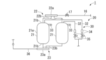
- FIG. 1 is a diagram showing an intermediate voltage circuit according to a first embodiment of the present disclosure.
- FIG. 7 is a diagram showing a medium voltage circuit according to a modification of the first embodiment of the present disclosure.
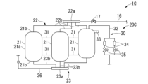
- FIG. 7 is a diagram showing a medium voltage circuit according to a second embodiment of the present disclosure.
- FIG. 7 is a diagram showing an intermediate voltage circuit according to a first modification of the second embodiment of the present disclosure. It is a figure showing the intermediate voltage circuit concerning the second modification of the second embodiment of this indication.
- FIG. 7 is a diagram showing a medium voltage circuit according to a third embodiment of the present disclosure.
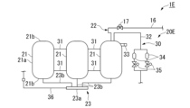
- FIG. 7 is a diagram showing a medium voltage circuit according to a fourth embodiment of the present disclosure.
- a refrigeration system 100 including an outdoor unit 1 according to a first embodiment of the present disclosure will be described with reference to FIGS. 1 and 2.
- the refrigeration apparatus 100 is used, for example, in a frozen warehouse.
- the refrigeration system 100 includes an outdoor unit 1 and an indoor unit 2.
- the outdoor unit 1 is a condensing unit including a first unit 3 and a second unit 4.
- the first unit 3 includes a compression section 10, an intermediate heat exchanger 13, an intermediate pressure circuit 20, a gas injection circuit 30, an accumulator 40, and a control device 6.
- the second unit 4 includes a capacitor 5.
- the indoor unit 2 includes an evaporator 7 that functions as a user-side heat exchanger.
- the refrigerant circuit of this embodiment includes a compression section 10, an intermediate heat exchanger 13, an intermediate pressure circuit 20, an accumulator 40, a condenser 5, an evaporator 7, piping connecting them, a control valve 35, and the like.
- the compression unit 10 compresses the refrigerant and supplies the compressed high temperature and high pressure refrigerant to the refrigerant circuit.
- CO 2 is used as the refrigerant.
- the compression section 10 is configured in a two-stage compression type.
- the compression section 10 includes a first compressor 11 and a second compressor 12.
- the first compressor 11 and the second compressor 12 are connected in series.
- the first compressor 11 is a low stage compression element
- the second compressor 12 is a high stage compression element.
- the flow direction of the refrigerant will be simply referred to as the "flow direction.”
- the first compressor 11 is the most upstream, and the upstream in the distribution direction is simply referred to as “upstream”, and the downstream in the distribution direction is simply referred to as "downstream”.
- a first suction pipe 11a and a first discharge pipe 11b are connected to the first compressor 11.
- a second suction pipe 12a and a second discharge pipe 12b are connected to the second compressor 12.
- the first discharge pipe 11b and the second suction pipe 12a are connected by an intermediate flow path 14.
- An intermediate heat exchanger 13 is provided in the intermediate flow path 14 . That is, the intermediate heat exchanger 13 is provided between the first compressor 11 and the second compressor 12 in the flow direction.
- the intermediate heat exchanger 13 functions as a cooler that cools the refrigerant discharged from the first compressor 11 and supplies it to the second compressor 12.
- the refrigerant supplied to the second compressor 12 is discharged through the second discharge pipe 12b.
- a gas pipe 15 is connected to the second discharge pipe 12b.
- the high-temperature, high-pressure refrigerant discharged from the second compressor 12 flows through the gas pipe 15 .
- the refrigerant flowing through the gas pipe 15 is supplied to the condenser 5 in the external second unit 4 through the first connection pipe 4a.
- the condenser 5 functions as a gas cooler that condenses the refrigerant.
- the refrigerant supplied to the condenser 5 is condensed by heat exchange with air sent by a fan (not shown). In the case of CO 2 refrigerant, it is cooled.
- the refrigerant cooled or condensed in the condenser 5 is returned to the gas-liquid two-phase pipe 16 in the first unit 3 through the second connection pipe 4b.
- the refrigerant flowing through the gas-liquid two-phase pipe 16 is expanded by a first expansion valve 17 provided in the gas-liquid two-phase pipe 16.
- the pressure is reduced to a medium pressure of about 6 MPa, for example.
- the gas-liquid two-phase refrigerant that has passed through the first expansion valve 17 is supplied to the intermediate pressure circuit 20 .
- the intermediate pressure circuit 20 includes a supply pipe 22, a receiver 21, and a discharge pipe 23.
- the supply pipe 22 includes a distribution section 22a and a supply side connection pipe 22b.
- the distribution part 22a is a header pipe connected to the gas-liquid two-phase pipe 16 downstream of the first expansion valve 17.
- the distribution section 22a is provided with three discharge ports.
- a supply side connecting pipe 22b is connected to each of the three discharge ports of the distribution section 22a.
- a total of three supply side connection pipes 22b are provided.
- the three supply-side connection pipes 22b are all formed to have equal lengths. Specifically, the difference between the length of the longest supply side connection pipe 22b and the length of the shortest supply side connection pipe 22b is 0 mm or more and 800 mm or less.
- One receiver 21 is connected to each supply side connecting pipe 22b.
- a total of three receivers 21 are provided. Each receiver 21 is formed in the same shape and has the same size.
- the receiver 21 is a pressure vessel having a body portion 21a and an end plate 21b.
- the body portion 21a is formed into a cylindrical shape whose axial direction coincides with the up-down direction.
- the mirror plate 21b is provided at both ends of the body portion 21a in the axial direction.
- the end plate 21b is formed in a dome shape that projects outward in the axial direction of the body 21a as it becomes spaced apart from the body 21a.
- other equipment such as the above-mentioned intermediate heat exchanger 13 is arranged above the receiver 21.
- the gas-liquid two-phase refrigerant expanded by the first expansion valve 17 is distributed to each receiver 21 by the distribution section 22a, and is supplied to each receiver 21 through each supply side connecting pipe 22b.
- Each receiver 21 separates the gas-liquid two-phase refrigerant into a gas refrigerant that is a gas-phase refrigerant and a liquid refrigerant that is a liquid-phase refrigerant, and stores the liquid refrigerant.
- Each receiver 21 is provided with a liquid level detection unit 33 that detects the level of liquid refrigerant stored therein.
- the liquid level detection unit 33 provided in each receiver 21 constitutes a gas injection circuit 30 that returns the gas refrigerant in the receiver 21 to the compression unit 10.
- the gas injection circuit 30 includes a gas injection pipe 32, a control valve 35, and a liquid level detection section 33.
- Gas injection pipe 32 discharges gas refrigerant from receiver 21 .
- a gas injection pipe 32 is provided in each receiver 21. That is, one gas injection pipe 32 is provided for each receiver 21 .
- the connection between the gas injection pipe 32 and the receiver 21 is provided above the receiver 21 and below the connection between the receiver 21 and the supply pipe 22.
- Each gas injection pipe 32 is provided with a strainer 34 .
- the gas injection pipes 32 join together on the downstream side and are connected to the intermediate pressure section of the second compressor 12. The gas refrigerant flowing through the gas injection pipe 32 passes through the strainer 34 and is returned to the second compressor 12.
- control valve 35 A control valve 35 is provided in each gas injection pipe 32.
- the control valve 35 is an electromagnetic control valve 35 that adjusts the flow rate of the gas refrigerant in the gas injection pipe 32 .
- the liquid level detection unit 33 is provided above the receiver 21 and below the connection between the receiver 21 and the gas injection pipe 32 .
- the liquid level detection unit 33 is a level switch that detects the liquid level of the liquid refrigerant by contact. When the level switch detects the liquid level, it sends a signal indicating a rise in the liquid level to the control device 6 (see FIG. 1).
- the control device 6 adjusts the opening degree of the control valve 35 based on the detection result of the liquid level detection section 33. In this embodiment, the control device 6 switches the opening and closing of the control valve 35 based on the signal from the level switch.
- the control device 6 is connected not only to the control valve 35 but also to each sensor, the compression section 10, and various valves (not shown). The control device 6 acquires the measured values from each sensor, adjusts the rotation speed of the compression section 10 and opening/closing of various valves, and operates the outdoor unit 1.
- the discharge pipe 23 discharges liquid refrigerant from the receiver 21 .
- the discharge pipe 23 is connected to the lower part of each receiver 21.
- the discharge pipe 23 includes a discharge side connecting pipe 23b and a merging portion 23a.
- One supply side connection pipe 22b is provided at the bottom of each receiver 21. That is, a total of three discharge side connecting pipes 23b are provided.
- the three discharge side connecting pipes 23b are all formed to have the same length. Specifically, the difference between the length of the longest discharge side connecting pipe 23b and the length of the shortest discharge side connecting pipe 23b is 0 mm or more and 800 mm or less.
- the confluence part 23a is a header pipe connected to the three discharge side connecting pipes 23b.
- a liquid pipe 36 is connected to the confluence section 23a.
- the liquid refrigerant in each receiver 21 passes through the discharge pipe 23 and is discharged to the liquid pipe 36.
- the liquid pipe 36 is provided with a supercooling heat exchanger (not shown).
- the refrigerant flowing through the liquid pipe 36 is cooled by the subcooling heat exchanger, and is supplied to the indoor unit 2 through the third connection pipe 2a.
- the indoor unit 2 is a unit cooler that includes a second expansion valve 8 and an evaporator 7.
- the refrigerant supplied to the indoor unit 2 is depressurized by the second expansion valve 8 and exchanges heat in the evaporator 7 to cool the object.
- the refrigerant after heat exchange returns to the outdoor unit 1 through the fourth connection pipe 2b.
- the fourth connection pipe 2b is connected to the return pipe 41 inside the outdoor unit 1.
- the refrigerant flowing through the fourth connection pipe 2b is supplied to the accumulator 40 through the return pipe 41.
- the accumulator 40 is connected to the first compressor 11 via the first suction pipe 11a.
- the accumulator 40 performs gas-liquid separation of the refrigerant supplied to the first compressor 11 .
- the gas refrigerant from which only the gas phase has been extracted by the accumulator 40 is supplied to the suction side of the first compressor 11.
- the receiver 21 when other equipment such as the intermediate heat exchanger 13 is arranged above the receiver 21, in order to enlarge the receiver 21, the receiver 21 must be enlarged in the radial direction.
- the body 21a of the receiver 21 can be manufactured using a tubular material previously formed into a tubular shape.
- the end plate 21b of the receiver 21 becomes thicker, and therefore a large press machine is required to process the end plate 21b. For this reason, increasing the size of the receiver 21 increases manufacturing costs.
- the outdoor unit 1 of the present embodiment has a plurality of receivers 21 , a supply pipe 22 that supplies refrigerant to each receiver 21 , and a discharge pipe 23 that discharges liquid refrigerant from each receiver 21 in the intermediate pressure circuit 20 .
- the supply pipe 22 has a distribution section 22a that distributes the refrigerant to each receiver 21.
- liquid refrigerant can be distributed to a plurality of receivers 21. Therefore, each receiver 21 can be made smaller compared to the case where only one receiver 21 is provided. Therefore, each receiver 21 can be manufactured using a ready-made tube material, so the receiver 21 can be manufactured easily.
- the end plate 21b can be made smaller, there is no need to use a large press machine. Therefore, according to this embodiment, manufacturing costs can be reduced.
- each receiver 21 can be made smaller, it becomes easier to adjust the arrangement of the receiver 21 in the outdoor unit 1 where various devices and piping are present, and each receiver 21 is made lighter. This facilitates handling of the receiver 21, so-called handling. Moreover, since each receiver 21 is reduced in weight, the strength necessary to support the weight of the receiver 21 can be easily ensured. Moreover, each receiver 21 is made into one unit by the distribution part 22a and the supply side connection pipe 22b, and the merging part 23a and the discharge side connection pipe 23b. This makes handling of the receiver 21 even easier. Therefore, design constraints can be reduced in terms of manufacturing costs, handling, and the like.
- each receiver 21 is provided with a gas injection pipe 32.
- the outdoor unit 1 also includes a liquid level detection section 33 that detects the liquid level of the liquid refrigerant stored in the receiver 21, a control valve 35 that adjusts the flow rate of the gas refrigerant in the gas injection pipe 32, and a liquid level detection section. 33, the control device 6 controls the opening degree of the control valve 35 in the gas injection pipe 32.
- the gas-liquid separation of the refrigerant can be automated, so that the gas-liquid separation of the refrigerant can be easily managed.
- one liquid level detection section 33 is provided in each receiver 21. Thereby, the gas-liquid separation of the refrigerant in each receiver 21 can be easily managed.
- the difference between the length of the longest supply side connection pipe 22b and the length of the shortest supply side connection pipe 22b is 0 mm or more and 800 mm or less, and the difference between the length of the longest discharge side connection pipe 23b and the length of the shortest supply side connection pipe 22b is 0 mm or more and 800 mm or less.
- the difference from the length of the shortest discharge side connecting pipe 23b is 0 mm or more and 800 mm or less.
- the outdoor unit 1A of the second embodiment further includes a communication pipe 31 that communicates each receiver 21 with the intermediate pressure circuit 20A.
- a plurality of receivers 21 are provided in the intermediate voltage circuit 20A.
- the number of receivers 21 in the medium voltage circuit 20A is two.
- the communication pipe 31 allows all the receivers 21 in the medium pressure circuit 20A to communicate with each other.
- the inner diameter of the communication tube 31 is, for example, 22.22 mm.
- the liquid level detection unit 33 is provided only in one of the plurality of receivers 21 .
- the communication pipe 31 allows liquid refrigerant to flow between all the receivers 21. Therefore, the heights of the liquid refrigerant stored in each receiver 21 can be made equal. Therefore, since the height of the liquid refrigerant level can be easily managed, controllability can be improved. Further, since the plurality of receivers 21 are communicated with each other through the communication pipe 31, the gas refrigerant can be moved between the plurality of receivers 21. Thereby, the pressure of the plurality of receivers 21 is equalized.
- each receiver 21 is provided with a gas injection pipe 32 and a communication pipe 31 is provided that communicates all the receivers 21, there is a difference in the height of the liquid refrigerant level between each receiver 21. The probability of this happening can be made extremely low. Thereby, simply by providing the liquid level detection section 33 in one of the plurality of receivers 21, the height of the liquid level of the liquid refrigerant can be sufficiently managed. Therefore, compared to the case where all the receivers 21 are provided with the liquid level detection section 33, the outdoor unit 1 can be simplified and the manufacturing cost can be reduced.
- each receiver 21 in the medium voltage circuit 20B is three.
- the length of each receiver 21 in the vertical direction is equal. Specifically, the difference between the length in the vertical direction of the receiver 21 having the longest length in the vertical direction and the length in the vertical direction of the receiver 21 having the shortest length in the vertical direction is 0 mm or more and 800 mm or less.
- each receiver 21 is formed in the same shape and has the same size. Only one of the three receivers 21 is provided with a gas injection pipe 32, and only the receiver 21 provided with the gas injection pipe 32 is provided with a liquid level detection section 33.
- the gas injection pipe 32 of this modification is branched into two at the middle part in the flow direction. Each branched gas injection pipe 32 is provided with one strainer 34 and one control valve 35.
- a plurality of communication pipes 31 are provided.
- Each receiver 21 forms one set of receivers 21 by connecting any two receivers 21 among the plurality of receivers 21 .
- two communication pipes 31 are provided vertically apart from each other.
- the upper communication pipe 31 mainly functions to move the gas refrigerant between the receivers 21, and the lower communication pipe 31 mainly functions to move the gas refrigerant between the receivers 21. Functions for the movement of liquid refrigerant.
- the communication pipes 31 belonging to different groups are provided at positions that overlap in the vertical direction. That is, the upper communicating pipes 31 belonging to different groups are provided at positions that overlap in the vertical direction, and the lower communicating pipes 31 belonging to different groups are provided at positions where they overlap in the vertical direction.
- a plurality of communication pipes 31 are provided spaced apart in the vertical direction.
- the height of the liquid level stored in each receiver 21 can be made equal in the early stage of refrigerant storage. Therefore, the height of the liquid refrigerant can be managed even more easily, so that controllability can be further improved.
- the communication pipes 31 belonging to different sets of receivers 21 are provided at positions that overlap in the vertical direction. Thereby, the height of the liquid level at which the liquid refrigerant starts flowing to other receivers 21 can be made the same in all the receivers 21 . Therefore, regardless of the number of receivers 21, the height of the liquid refrigerant can be managed more easily, so that controllability can be further improved.
- the difference between the length in the vertical direction of the receiver 21 having the longest length in the vertical direction and the length in the vertical direction of the receiver 21 having the shortest length in the vertical direction is 0 mm or more and 800 mm or less.
- one receiver 21 provided with the gas injection pipe 32 in the second modification described above is longer in the vertical direction than the other receivers 21. It is also possible to adopt one formed in . Thereby, the capacity of some receivers 21 provided with gas injection pipes 32 can be increased.
- FIG. 7 an outdoor unit 1D according to a third embodiment of the present disclosure will be described with reference to FIG. 7.
- the same reference numerals are given to the same components as in each of the above-described embodiments, and detailed description thereof will be omitted as appropriate.
- the distribution section 22a performs gas-liquid separation of the refrigerant.
- the distribution section 22a is a distribution pipe 22a1 that separates the refrigerant into liquid refrigerant and gas refrigerant and stores the liquid refrigerant.
- the distribution pipe 22a1 is formed to extend in one direction.
- the distribution pipe 22a1 is. It is arranged so as to extend obliquely to the horizontal direction.
- the gas injection pipe 32 is connected to the distribution pipe 22a1.
- the connection between the gas injection pipe 32 and the distribution pipe 22a1 is arranged above the connection between the supply side connection pipe 22b and the distribution pipe 22a1.
- the liquid level detection section 33 is provided in the distribution pipe 22a1.
- the liquid level detection unit 33 is provided above the connection between the supply side connection pipe 22b and the distribution pipe 22a1 and below the connection between the gas injection pipe 32 and the distribution pipe 22a1.
- gas-liquid separation of the refrigerant can be performed in the distribution section 22a on the upstream side of the receiver 21.
- the entire capacity of the receiver 21 can be utilized for storing liquid refrigerant, so there is no need to provide a space in each receiver 21 to be filled with gas refrigerant. Therefore, each receiver 21 can be further downsized, and design constraints can be further reduced.
- the distribution part 22a is a distribution pipe 22a1 extending in one direction.
- the refrigerant can be separated into gas and liquid in a relatively narrow space between the receiver 21 and the other equipment. A mechanism can be provided to do so. Therefore, design constraints can be further reduced.
- the distribution pipe 22a1 is arranged at an angle with respect to the horizontal direction. As a result, compared to the case where the distribution pipe 22a1 is disposed along the horizontal direction, the timing at which the liquid level detection unit 33 detects the liquid refrigerant level can be delayed, so the capacity of the distribution pipe 22a1 can be further increased. It can be used a lot.
- the distribution section 22a is the distribution pipe 22a1, but the present invention is not limited to this, and the distribution section 22a may be an auxiliary tank for storage.
- an outdoor unit 1E according to a fourth embodiment of the present disclosure will be described with reference to FIG. 8.
- the same components as in each embodiment described above are given the same reference numerals, and detailed explanations are omitted as appropriate.
- the refrigerant is directly supplied to one receiver 21 among the plurality of receivers 21 through one supply pipe 22.
- the outdoor unit 1E of this embodiment includes an intermediate pressure circuit 20E, a gas injection circuit 30, and a control device 6 (see FIG. 1).
- the intermediate pressure circuit 20E includes a receiver 21, a supply pipe 22, a communication pipe 31, and a discharge pipe 23.
- a plurality of receivers 21 (a total of three in this embodiment) are provided. All the receivers 21 are formed in the same shape, have the same size, and are arranged at the same vertical position.
- One supply pipe 22 is provided in one receiver 21 among the plurality of receivers 21.
- the supply pipe 22 connects the gas-liquid two-phase pipe 16 and the receiver 21 .
- the communication pipe 31 is provided between the plurality of receivers 21.
- a plurality of communication pipes 31 are provided spaced apart in the vertical direction.
- the communication pipes 31 belonging to different sets of receivers 21 are provided at positions that overlap in the vertical direction.
- the communication pipe 31 connects the adjacent receivers 21, and allows one receiver 21 connected to the supply pipe 22 to communicate with the remaining receivers 21.
- two communication pipes 31 are provided for each set of adjacent receivers 21, one at the top and one at the bottom.
- the upper communication pipe 31 mainly functions to move the gas refrigerant between the receivers 21, and the lower communication pipe 31 mainly functions to move the gas refrigerant between the receivers 21. Functions for the movement of liquid refrigerant.
- the discharge pipe 23 discharges liquid refrigerant from each receiver 21.
- the discharge pipe 23 has a merging section 23a and a discharge side connecting pipe 23b.
- the merging portion 23a merges liquid refrigerant discharged from each receiver 21.
- One discharge side connecting pipe 23b is provided for each receiver 21.
- the discharge side connecting pipe 23b connects the merging portion 23a and each receiver 21.
- the gas injection circuit 30 includes a gas injection pipe 32, a control valve 35, and a liquid level detection section 33.
- the gas injection pipe 32 is provided in one receiver 21 to which the supply pipe 22 is connected.
- the gas injection pipe 32 discharges gas refrigerant among the refrigerants from the receiver 21 .
- the liquid level detection unit 33 is provided in one receiver 21 in which the gas injection pipe 32 is provided.
- the liquid level detection section 33 is provided on the end plate 21b of the receiver 21 and is located below the connection section between the supply pipe 22 and the receiver 21.
- the liquid level detection unit 33 detects the liquid level of the liquid refrigerant stored in one receiver 21 .
- the control valve 35 is provided in the gas injection pipe 32 and adjusts the flow rate of the gas refrigerant within the gas injection pipe 32.
- the control device 6 controls the opening degree of the control valve 35 based on the detection result of the liquid level detection section 33.
- the refrigerant is directly supplied from the supply pipe 22 to one receiver 21 in which the liquid level detection section 33 is provided among the plurality of receivers 21.
- gas refrigerant is distributed to other receivers 21 through the communication pipe 31 .
- the pressure of the plurality of receivers 21 is equalized.
- the gas refrigerant is drawn out of the receiver 21 through the gas injection pipe 32.
- liquid refrigerant among the refrigerants supplied into the receiver 21 is temporarily stored within the receiver 21 and transferred to the downstream side through the discharge pipe 23.
- the liquid refrigerant stored in the receiver 21 reaches the height of the lower communication pipe 31, it is supplied into the other receivers 21 through the communication pipe 31. In this way, the refrigerant is distributed to the plurality of receivers 21 in a well-balanced manner.
- the outdoor unit 1E includes a plurality of receivers 21 that store liquid refrigerant among refrigerants, a supply pipe 22 that is connected to one of the plurality of receivers 21 and supplies refrigerant to one receiver 21, It includes a communication pipe 31 that communicates one receiver 21 with the remaining receivers 21, and a discharge pipe 23 that discharges liquid refrigerant from each receiver 21, and the discharge pipe 23 joins the liquid refrigerant discharged from each receiver 21. and a plurality of discharge-side connecting pipes 23b that connect the merging portion 23a and each receiver.
- gas refrigerant can be distributed among a plurality of receivers 21 while storing liquid refrigerant in one receiver 21. Therefore, each receiver 21 can be made smaller compared to the case where only one receiver 21 is provided. Therefore, according to this embodiment, the manufacturing cost of the entire device can be reduced, and handling of the receiver 21, so-called handling, becomes easy. Therefore, design constraints can be reduced in terms of manufacturing costs, handling, and the like.
- a plurality of communication pipes 31 are provided spaced apart in the vertical direction.
- the height of the liquid level stored in each receiver 21 can be made equal in the early stage of refrigerant storage mainly by the lower communication pipe 31. Therefore, since the height of the liquid refrigerant can be easily managed, controllability can be improved. Further, the gas refrigerant can be moved between the receivers 21 mainly by the upper communication pipe 31.
- three receivers 21 are provided. Further, among the sets of receivers 21 communicated through the communication pipes 31, the communication pipes 31 belonging to different sets of receivers 21 are provided at positions that overlap in the vertical direction.
- the height of the liquid level at which the liquid refrigerant starts flowing to other receivers 21 can be made the same in all the receivers 21. Therefore, regardless of the number of receivers 21, the height of the liquid refrigerant can be managed more easily, so that controllability can be further improved.
- the outdoor unit 1E is provided in one receiver 21 to which a supply pipe 22 is connected, and is provided with a gas injection pipe 32 for discharging gas refrigerant from the receiver 21 among refrigerants, and a gas injection pipe 32.
- a liquid level detection unit 33 is provided in one receiver 21 to detect the liquid level of the liquid refrigerant stored in one receiver 21, and a liquid level detection unit 33 is provided in the gas injection pipe 32 to detect the flow rate of the gas refrigerant in the gas injection pipe 32. It includes a control valve 35 to be adjusted, and a control device 6 to control the opening degree of the control valve 35 based on the detection result of the liquid level detection section 33.
- the outdoor unit 1E can be simplified and the manufacturing cost can be reduced.
- two communication pipes 31 are provided for each set of adjacent receivers 21, one at the top and one at the top, but the present invention is not limited to this. Only one communication pipe 31 is provided for each set of adjacent receivers 21, and for example, the lower communication pipe 31 of the two communication pipes 31 may not be provided.
- all the receivers 21 are formed in the same shape, have the same size, and are arranged at the same vertical position, but the invention is not limited to this.
- the shapes of the plurality of receivers 21 may be different from each other.
- the receiver 21 provided with the gas injection pipe 32 may be longer in the vertical direction than the other receivers 21.
- the plurality of receivers 21 may be arranged such that the upper end of the receiver 21 provided with the gas injection pipe 32 among the plurality of receivers 21 is located above the upper ends of the other receivers 21. Further, the number of receivers 21 can be changed as appropriate.
- the refrigeration device 100 is used for a frozen warehouse or the like, but the invention is not limited to this, and the refrigeration device 100 may be used for air conditioning of an office building, a commercial facility, a factory, or the like.
- CO 2 is used as the refrigerant, but the present invention is not limited to this, and propane gas, butane, propylene, or the like may be used as the refrigerant.
- the number of receivers 21 in the medium voltage circuits 20, 20A, 20B, 20C, 20D, and 20E is 2 or 3, but is not limited to this, and may be 4 or more. You can.
- a plurality of communication pipes 31 may be provided spaced apart in the vertical direction. Furthermore, in the outdoor units 1A and 1D, three or more receivers 21 are provided, and among the sets of receivers 21 communicated through the communication pipes 31, the communication pipes 31 belonging to different groups are provided at positions that overlap in the vertical direction. It may be.
- the outdoor unit 1E is connected to a plurality of receivers 21 that store liquid refrigerant among refrigerants, and one of the plurality of receivers 21, and supplies the refrigerant to the one receiver 21.
- a communication pipe 31 that communicates the one receiver 21 with the remaining receivers 21, and a discharge pipe 23 that discharges the liquid refrigerant from each receiver 21.
- a merging portion 23a for merging the liquid refrigerant discharged from each of the receivers 21, and a plurality of discharge side connecting pipes 23b for connecting the merging portion 23a and each of the receivers 21.
- each receiver 21 can be made smaller, and design restrictions can be reduced.
- the outdoor unit 1E of the second aspect is the outdoor unit 1E of the first aspect, and a plurality of the communication pipes 31 may be provided spaced apart in the vertical direction.
- the height of the liquid level stored in each receiver 21 can be made equal in the early stage of refrigerant storage mainly by the lower communication pipe 31. Therefore, the height of the liquid refrigerant can be easily managed. Further, the gas refrigerant can be moved between the receivers 21 mainly by the upper communication pipe 31.
- the outdoor unit 1E of the third aspect is the outdoor unit 1E of the first or second aspect, and the receivers 21 are provided with three or more receivers 21 and communicated with each other through the communication pipe 31.
- the communication pipes 31 belonging to different groups among the 21 groups may be provided at positions that overlap in the vertical direction.
- the height of the liquid level at which the liquid refrigerant starts flowing to other receivers 21 can be made the same in all the receivers 21. Therefore, regardless of the number of receivers 21, the height of the liquid refrigerant can be managed even more easily.
- the outdoor unit 1E of the fourth aspect is the outdoor unit 1E of any one of the first to third aspects, and is provided in the one receiver 21 to which the supply pipe 22 is connected;
- a gas injection pipe 32 for discharging gas refrigerant from the receiver 21 among the refrigerants, and a liquid refrigerant that is provided in the one receiver 21 provided with the gas injection pipe 32 and stored in the one receiver 21.
- a liquid level detection unit 33 that detects the surface, a control valve 35 that is provided in the gas injection pipe 32 and that adjusts the flow rate of the gas refrigerant in the gas injection pipe 32, and
- the control device 6 may also include a control device 6 that controls the opening degree of the control valve 35 based on the control valve 35 .
- the outdoor unit 1E can be simplified and the manufacturing cost can be reduced.
- the outdoor units 1, 1A, 1B, 1C, and 1D include a plurality of receivers 21 that store liquid refrigerant among refrigerants, and a supply pipe 22 that supplies the refrigerant to each of the receivers 21.
- a discharge pipe 23 that discharges the liquid refrigerant from each of the receivers 21, and the supply pipe 22 includes a distribution section 22a that distributes the refrigerant to each of the receivers 21, and a distributing section 22a and each of the receivers 21.
- the discharge pipe 23 has a plurality of supply side connecting pipes 22b that connect the liquid refrigerant discharged from each of the receivers 21, and a merging part 23a that joins the liquid refrigerant discharged from each of the receivers 21. 21, and a plurality of discharge side connecting pipes 23b.
- each receiver 21 can be made smaller, and design restrictions can be reduced.
- the outdoor units 1 and 1A of the sixth aspect are the outdoor units 1 and 1A of the fifth aspect, and are provided in each of the receivers 21 and discharge gas refrigerant among the refrigerants from the receivers 21.
- a plurality of gas injection pipes 32 a liquid level detection unit 33 that detects the liquid level of the liquid refrigerant stored in the receiver 21; It may also include a control valve 35 that adjusts the flow rate of the liquid, and a control device 6 that controls the opening degree of the control valve 35 based on the detection result of the liquid level detection section 33.
- the outdoor unit 1D according to the seventh aspect is the outdoor unit 1D according to the fifth aspect, in which the distribution section 22a is arranged to extend obliquely with respect to the horizontal direction, and the distribution section 22a is arranged to extend at an angle with respect to the horizontal direction, and A distribution pipe 22a1 that separates the liquid refrigerant into gas and gas refrigerant and stores the liquid refrigerant, a gas injection pipe 32 provided in the distribution pipe 22a1 and discharging the gas refrigerant, and a gas injection pipe 32 provided in the distribution pipe 22a1,
- the refrigerant may further include a liquid level detection section 33 that detects the liquid level of the stored liquid refrigerant.
- gas-liquid separation of the refrigerant can be performed in the distribution section 22a, so the entire capacity of the receiver 21 can be utilized for storing liquid refrigerant.
- the outdoor units 1A, 1D of the eighth aspect are the outdoor units 1A, 1D of any one of the fifth to seventh aspects, and include a communication pipe 31 that connects all of the plurality of receivers 21. You can.
- the outdoor units 1A, 1D of the ninth aspect are the outdoor units 1A, 1D of the eighth aspect, and a plurality of the communication pipes 31 may be provided spaced apart in the vertical direction.
- the height of the liquid level stored in each receiver 21 can be made equal in the early stage of refrigerant storage. Therefore, the height of the liquid refrigerant can be managed even more easily.
- the outdoor units 1A, 1D of the tenth aspect are the outdoor units 1A, 1D of the eighth or ninth aspect, and the receivers 21 are provided with three or more and communicated through the communication pipe 31.
- the communication pipes 31 belonging to different sets of the receivers 21 may be provided at positions that overlap in the vertical direction.
- the height of the liquid level at which the liquid refrigerant starts flowing to other receivers 21 can be made the same in all the receivers 21. Therefore, regardless of the number of receivers 21, the height of the liquid refrigerant can be managed even more easily.
- the outdoor units 1B, 1C of the eleventh aspect are the outdoor units 1B, 1C of the fifth aspect, and include a communication pipe 31 that connects all of the plurality of receivers 21, and one of the plurality of receivers 21.
- a gas injection pipe 32 is provided in some of the receivers 21 and discharges gas refrigerant among the refrigerants from the receiver 21, and a gas injection pipe 32 is provided in some of the receivers 21 in which the gas injection pipe 32 is provided, a liquid level detection unit 33 that detects the liquid level of the liquid refrigerant stored in the receiver 21; and a control valve 35 that is provided in the gas injection pipe 32 and adjusts the flow rate of the gas refrigerant in the gas injection pipe 32. and a control device 6 that controls the opening degree of the control valve 35 based on the detection result of the liquid level detection section 33.
- the outdoor units 1B and 1C can be simplified and the manufacturing cost can be reduced.
- the outdoor unit 1C of the twelfth aspect is the outdoor unit 1C of the eleventh aspect, in which the upper end of some of the receivers 21 provided with the gas injection pipes 32 among the plurality of receivers 21 is , may be located above the upper ends of the other receivers 21.
- the outdoor unit 1C of the thirteenth aspect is the outdoor unit 1C of the twelfth aspect, and some of the receivers 21 provided with the gas injection pipes 32 among the plurality of receivers 21 are It may be longer than the receiver 21 in the vertical direction.
- the outdoor units 1B, 1C of the fourteenth aspect are the outdoor units 1B, 1C of the eleventh or twelfth aspect, and the length in the vertical direction of the receiver 21 having the longest length in the vertical direction;
- the difference between the receiver 21 having the shortest length in the vertical direction and the length in the vertical direction may be 0 mm or more and 800 mm or less.
- the allowable height of the liquid refrigerant can be made uniform among the plurality of receivers 21. Therefore, the height of the liquid refrigerant stored in the receiver 21 can be managed even more easily.
- the outdoor units 1B, 1C of the fifteenth aspect are the outdoor units 1B, 1C of any one of the eleventh to fourteenth aspects, and the communication pipes 31 are provided in plurality spaced apart in the vertical direction. It may be.
- the outdoor units 1B, 1C of the sixteenth aspect are the outdoor units 1B, 1C of any one of the eleventh to fifteenth aspects, and the receivers 21 are provided with three or more, and the communication The communication pipes 31 belonging to different sets of the receivers 21 communicated through the pipes 31 may be provided at positions that overlap in the vertical direction.
- the outdoor units 1, 1A, 1B, 1C, 1D of the 17th aspect are the outdoor units 1, 1A, 1B, 1C, 1D of any one of the 5th to 16th aspects, and are the longest
- the difference between the length of the supply-side connecting pipe 22b and the shortest supply-side connecting pipe 22b is 0 mm or more and 800 mm or less
- the difference between the length of the longest discharge-side connecting pipe 23b and the shortest discharge-side connecting pipe 23b is 0 mm or more and 800 mm or less.
- the difference from the length of may be 0 mm or more and 800 mm or less.
Landscapes
- Engineering & Computer Science (AREA)
- Physics & Mathematics (AREA)
- Mechanical Engineering (AREA)
- Thermal Sciences (AREA)
- General Engineering & Computer Science (AREA)
- Other Air-Conditioning Systems (AREA)
Abstract
Description
本願は、2022年7月11日に日本に出願された特願2022-111116号について優先権を主張し、その内容をここに援用する。
(冷凍装置)
以下、本開示の第一実施形態に係る室外機1を備えた冷凍装置100について、図1、図2を参照して説明する。冷凍装置100は、例えば冷凍倉庫等に用いられる。
図1に示すように、冷凍装置100は、室外機1と、室内機2と、を備える。
本実施形態の冷媒回路は、圧縮部10、中間熱交換器13、中圧回路20、アキュムレータ40、コンデンサ5及びエバポレータ7、それらを接続する配管や制御弁35等を含んで構成される。
第1圧縮機11には、第1吸入管11a及び第1吐出管11bが接続される。第2圧縮機12には、第2吸入管12a及び第2吐出管12bが接続される。第1吐出管11bと第2吸入管12aとは、中間流路14によって接続される。
第2圧縮機12に供給された冷媒は、第2吐出管12bを通じて吐出される。第2吐出管12bには、ガス管15が接続される。第2圧縮機12から吐出された高温高圧の冷媒は、ガス管15を流れる。
供給管22は、分配部22aと、供給側接続管22bと、を備える。分配部22aは、気液二相管16の第1膨張弁17よりも下流側に接続されるヘッダー管である。分配部22aには、3つの排出口が設けられている。分配部22aの3つの排出口には、それぞれ供給側接続管22bが接続されている。
レシーバ21は、計3つ設けられている。各レシーバ21は、同形状に形成され、大きさも等しい。レシーバ21は、胴部21aと、鏡板21bと、を有する圧力容器である。胴部21aは、軸線方向が上下方向と一致する円筒状に形成されている。鏡板21bは、胴部21aの軸線方向両端部に設けられている。鏡板21bは、胴部21aから離間するに従い胴部21aの軸線方向外側に張り出すドーム状に形成されている。また、レシーバ21の上方には、上述した中間熱交換器13等の他の機器が配置される。
各レシーバ21に設けられた液面検出部33は、レシーバ21内のガス冷媒を圧縮部10に戻すガスインジェクション回路30を構成する。ガスインジェクション回路30は、ガスインジェクション管32と、制御弁35と、液面検出部33と、を備える。
ガスインジェクション管32は、ガス冷媒をレシーバ21から排出する。ガスインジェクション管32は、各レシーバ21に設けられている。すなわち、ガスインジェクション管32は、全てのレシーバ21に1本ずつ設けられている。ガスインジェクション管32とレシーバ21との接続部は、レシーバ21の上部であって、レシーバ21と供給管22との接続部よりも下方に設けられている。各ガスインジェクション管32には、ストレーナ34が設けられている。各ガスインジェクション管32は、下流側で合流し、第2圧縮機12の中圧部に接続される。ガスインジェクション管32を流れるガス冷媒は、ストレーナ34を通って、第2圧縮機12に戻される。
制御弁35は、各ガスインジェクション管32に設けられている。制御弁35は、ガスインジェクション管32内のガス冷媒の流量を調節する電磁式の制御弁35である。
液面検出部33は、レシーバ21の上部であって、レシーバ21とのガスインジェクション管32との接続よりも下方に設けられている。液面検出部33は、接触により液冷媒の液面を検出するレベルスイッチである。レベルスイッチは、液面を検出すると、制御装置6(図1参照)に液面の上昇を示す信号を送信する。
制御装置6は、液面検出部33の検出結果に基づいて、制御弁35の開度を調整する。本実施形態では、制御装置6は、レベルスイッチからの信号に基づいて、制御弁35の開閉を切り替える。
制御装置6は、制御弁35だけでなく、不図示の各センサや圧縮部10、各種弁と接続されている。制御装置6は、各センサによる計測値を取得し、圧縮部10の回転数や各種弁の開閉を調整し、室外機1を運転する。
排出管23は、レシーバ21から液冷媒を排出する。排出管23は、各レシーバ21の下部に接続されている。排出管23は、排出側接続管23bと、合流部23aと、を備える。
合流部23aは、3本の排出側接続管23bに接続されるヘッダー管である。合流部23aには、液管36が接続される。
ところで、レシーバ21の上方に中間熱交換器13等の他の機器が配置される場合、レシーバ21を大型化するには、レシーバ21を径方向に大型化しなければならない。レシーバ21が所定の容積以下の場合、予め管状に形成された管材を用いてレシーバ21の胴部21aを製造することができる。しかしながら、レシーバ21が所定の容積以上の場合、複数の平板をプレス成形によりロールし、溶接する等して胴部21aを製造する必要がある。また、レシーバ21が大型化する程、レシーバ21の鏡板21bが肉厚化するため、鏡板21bの加工に大型のプレス機が必要となる。このため、レシーバ21を大型化すると、製造コストが増大してしまう。
また、各レシーバ21は、分配部22a及び供給側接続管22bと、合流部23a及び排出側接続管23bとによって、1つのユニットとされている。これにより、レシーバ21の取扱いがより一層容易となる。
よって、製造コストや取扱い等の観点から、設計上の制約を軽減することができる。
また、室外機1は、レシーバ21に貯留される液冷媒の液面を検出する液面検出部33と、ガスインジェクション管32内のガス冷媒の流量を調節する制御弁35と、液面検出部33の検出結果に基づいて、ガスインジェクション管32内の制御弁35の開度を制御する制御装置6と、を備える。これにより、冷媒の気液分離を自動化することができるので、冷媒の気液分離を容易に管理することができる。
また、液面検出部33は、各レシーバ21に1つずつ設けられている。これにより、各レシーバ21の冷媒の気液分離の管理を容易に行うことできる。
図3を参照して、第一実施形態の変形例について説明する。第一実施形態では、レシーバ21は3つ設けられていたのに対し、この変形例では、レシーバ21は2つ設けられている。
以下、本開示の第二実施形態に係る室外機1Aについて、図4を参照して説明する。第二実施形態では、第一実施形態と同様の構成要素については同一の符号を付して詳細な説明を適宜省略する。第二実施形態の室外機1Aは、中圧回路20Aに各レシーバ21を連通させる連通管31をさらに備える。
連通管31は、中圧回路20A内の全てのレシーバ21を連通させる。連通管31の内径は、例えば22.22mmである。液面検出部33は、複数のレシーバ21のうち1つのレシーバ21にのみ設けられている。
本実施形態の室外機1Aでは、連通管31により、全てのレシーバ21間で液冷媒を流動可能とすることができる。したがって、各レシーバ21に貯留される液冷媒の液面の高さを揃えることができる。よって、液冷媒の液面の高さを容易に管理することができるので、制御性を向上させることができる。
また、複数のレシーバ21は連通管31によって連通されているため、複数のレシーバ21間でガス冷媒が移動可能となる。これにより、複数のレシーバ21が均圧化される。
図5を参照して、第二実施形態の第一変形例について説明する。
図5に示すように、本変形例の室外機1Bでは、中圧回路20B内のレシーバ21の個数は、3個である。各レシーバ21の上下方向の長さは等しい。具体的には、上下方向の長さが最長のレシーバ21の上下方向の長さと、上下方向の長さが最短のレシーバ21の上下方向の長さと、の差は、0mm以上800mm以下である。さらに、本実施形態では、各レシーバ21は、同形状に形成され、大きさも等しい。3つのレシーバ21のうち1つのレシーバ21にのみガスインジェクション管32が設けられ、ガスインジェクション管32が設けられるレシーバ21にのみ液面検出部33が設けられている。
本変形例のガスインジェクション管32は、流通方向の中間部において2本に分岐している。分岐した各ガスインジェクション管32には、ストレーナ34と制御弁35とが1つずつ設けられている。
本変形例では、全てのレシーバ21を連通させる連通管31が設けられていることにより、各レシーバ21で液冷媒の液面の高さに差が生じる蓋然性を低くすることができる。これにより、ガスインジェクション管32が設けられたレシーバ21にのみ液面検出部33が設けるだけで、液冷媒の液面の高さを十分に管理することができる。したがって、全てのレシーバ21にガスインジェクション管32及び液面検出部33を設ける場合と比較して、室外機1を簡素化し、製造コストを低減することができる。
図6を参照して、第二実施形態の第二変形例について説明する。
図6に示すように、本変形例の室外機1Cの中圧回路20Cでは、3つのレシーバ21のうちガスインジェクション管32が設けられた1つのレシーバ21は、他のレシーバ21よりも例えば100mm浮かせて配置されている。すなわち、3つのレシーバ21のうちガスインジェクション管32が設けられた1つのレシーバ21の上端は、他のレシーバ21の上端よりも上方に位置する。これにより、ガスインジェクション管32が設けられたレシーバ21の上方にガス冷媒が充填される空間を残すことができる。このため、ガスインジェクション管32が設けられていない他のレシーバ21の全ての容量を液冷媒の貯留に活用することができる。
ここで第二実施形態の室外機1Cの第三変形例として、上述した第二変形例におけるガスインジェクション管32が設けられた1つのレシーバ21が、他のレシーバ21よりも上下方向に長くなるように形成されたものを採用してもよい。これにより、ガスインジェクション管32が設けられた一部のレシーバ21の容量を増大することができる。
以下、本開示の第三実施形態に係る室外機1Dについて、図7を参照して説明する。第三実施形態では、上述した各実施形態と同様の構成要素については同一の符号を付して詳細な説明を適宜省略する。第三実施形態の室外機1Dの中圧回路20Dでは、分配部22aで冷媒の気液分離を行う。
本実施形態では、レシーバ21よりも上流側の分配部22aで冷媒の気液分離を行うことができる。これにより、レシーバ21の容量をすべて液冷媒の貯留に活用することができるので、各レシーバ21にガス冷媒が充填される空間を設ける必要がなくなる。したがって、各レシーバ21をより一層小型化することができるので、設計上の制約をより一層軽減することができる。
また、分配管22a1は、水平方向に対して傾いて配置されている。これにより、分配管22a1が水平方向に沿って配置される場合と比較して、液面検出部33が液冷媒の液面を検出するタイミングを遅らせることができるので、分配管22a1の容量をより多く活用することができる。
以下、本開示の第四実施形態に係る室外機1Eについて、図8を参照して説明する。第四実施形態では、上述した各実施形態と同様の構成要素については同一の符号を付して詳細な説明を適宜省略する。第四実施形態の室外機1Eの中圧回路20Eでは、1本の供給管22によって、複数のレシーバ21のうち1つのレシーバ21に冷媒が直接供給される。
ガスインジェクション管32は、供給管22が接続された1つのレシーバ21に設けられている。ガスインジェクション管32は、冷媒のうちガス冷媒をレシーバ21から排出する。
本実施形態の室外機1Eでは、複数のレシーバ21のうち液面検出部33が設けられた1つのレシーバ21に供給管22から冷媒が直接供給される。レシーバ21内に供給された冷媒のうちガス冷媒は、連通管31を通じて他のレシーバ21に分配される。これにより、複数のレシーバ21が均圧化される。ガス冷媒は、ガスインジェクション管32を通ってレシーバ21外に引き出される。
このようにして、複数のレシーバ21に冷媒がバランスよく分配される。
また、レシーバ21の個数は、適宜変更可能である。
以上、本開示の実施の形態について図面を参照して詳述したが、具体的な構成はこの実施の形態に限られるものではなく、本開示の要旨を逸脱しない範囲の設計変更等も含まれる。上記各実施形態、及び各変形例を適宜組み合わせてもよい。
なお、上記実施形態では、冷凍装置100は、冷凍倉庫等に用いられるとしたが、これに限られず、冷凍装置100は、オフィスビルや商業施設、工場等の空調に用いられてもよい。
なお、上記実施形態では、冷媒には、例えば、CO2が用いられるとしたが、これに限られず、冷媒には、例えば、プロパンガスやブタン、プロピレン等が用いられてもよい。
各実施形態に記載の室外機1,1A,1B,1C,1D,1Eは、例えば以下のように把握される。
Claims (17)
- 冷媒のうち液冷媒を貯留する複数のレシーバと、
複数の前記レシーバの1つに接続され、前記1つのレシーバに前記冷媒を供給する供給管と、
前記1つのレシーバと残りの前記レシーバとを連通させる連通管と、
各前記レシーバから前記液冷媒を排出する排出管と、
を備え、
前記排出管は、
各前記レシーバから排出される前記液冷媒を合流させる合流部と、
前記合流部と各前記レシーバとを接続する複数の排出側接続管と、
を有する室外機。 - 前記連通管は、上下方向に離間して複数設けられている請求項1に記載の室外機。
- 前記レシーバは、3つ以上設けられるとともに、
前記連通管で連通される前記レシーバの組のうち異なる前記組に属する前記連通管同士は、上下方向で重なる位置に設けられている請求項1又は2に記載の室外機。 - 前記供給管が接続された前記1つのレシーバに設けられ、前記冷媒のうちガス冷媒を前記レシーバから排出するガスインジェクション管と、
前記ガスインジェクション管が設けられた前記1つのレシーバに設けられ、前記1つのレシーバに貯留される前記液冷媒の液面を検出する液面検出部と、
前記ガスインジェクション管に設けられ、前記ガスインジェクション管内の前記ガス冷媒の流量を調節する制御弁と、
前記液面検出部の検出結果に基づいて、前記制御弁の開度を制御する制御装置と、
を備える請求項1又は2に記載の室外機。 - 冷媒のうち液冷媒を貯留する複数のレシーバと、
各前記レシーバに前記冷媒を供給する供給管と、
各前記レシーバから前記液冷媒を排出する排出管と、
を備え、
前記供給管は、
前記冷媒を各前記レシーバに分配する分配部と、
前記分配部と各前記レシーバとを接続する複数の供給側接続管と、
を有し、
前記排出管は、
各前記レシーバから排出される前記液冷媒を合流させる合流部と、
前記合流部と各前記レシーバとを接続する複数の排出側接続管と、
を有する室外機。 - 各前記レシーバに設けられ、前記冷媒のうちガス冷媒を前記レシーバから排出する複数のガスインジェクション管と、
前記レシーバに貯留される前記液冷媒の液面を検出する液面検出部と、
前記ガスインジェクション管に設けられ、前記ガスインジェクション管内の前記ガス冷媒の流量を調節する制御弁と、
前記液面検出部の検出結果に基づいて、前記制御弁の開度を制御する制御装置と、
を備える請求項5に記載の室外機。 - 前記分配部は、水平方向に対して傾いて延びるように配置され、前記冷媒を前記液冷媒とガス冷媒とに気液分離して前記液冷媒を貯留する分配管であり、
前記分配管に設けられ、前記ガス冷媒を排出するガスインジェクション管と、
前記分配管に設けられ、前記貯留される前記液冷媒の液面を検出する液面検出部と、を備える請求項5に記載の室外機。 - 複数の前記レシーバを全て連通させる連通管を備える請求項5から請求項7のいずれか一項に記載の室外機。
- 前記連通管は、上下方向に離間して複数設けられている請求項8に記載の室外機。
- 前記レシーバは、3つ以上設けられるとともに、
前記連通管で連通される前記レシーバの組のうち異なる前記組に属する前記連通管同士は、上下方向で重なる位置に設けられている請求項8に記載の室外機。 - 複数の前記レシーバを全て連通させる連通管と、
複数の前記レシーバのうち一部の前記レシーバにそれぞれ設けられ、前記冷媒のうちガス冷媒を前記レシーバから排出するガスインジェクション管と、
前記ガスインジェクション管が設けられた一部の前記レシーバにそれぞれ設けられ、前記レシーバに貯留される前記液冷媒の液面を検出する液面検出部と、
前記ガスインジェクション管に設けられ、前記ガスインジェクション管内の前記ガス冷媒の流量を調節する制御弁と、
前記液面検出部の検出結果に基づいて、前記制御弁の開度を制御する制御装置と、
を備える請求項5に記載の室外機。 - 複数の前記レシーバのうち前記ガスインジェクション管が設けられた一部の前記レシーバの上端は、他の前記レシーバの上端よりも上方に位置する請求項11に記載の室外機。
- 複数の前記レシーバのうち前記ガスインジェクション管が設けられた一部の前記レシーバは、他の前記レシーバよりも上下方向に長い請求項12に記載の室外機。
- 上下方向の長さが最長の前記レシーバの上下方向の長さと、上下方向の長さが最短の前記レシーバの上下方向の長さと、の差は、0mm以上800mm以下である請求項11または請求項12に記載の室外機。
- 前記連通管は、上下方向に離間して複数設けられている請求項11から請求項13のいずれか一項に記載の室外機。
- 前記レシーバは、3つ以上設けられるとともに、
前記連通管で連通される前記レシーバの組のうち異なる前記組に属する前記連通管同士は、上下方向で重なる位置に設けられている請求項11から請求項13のいずれか一項に記載の室外機。 - 最長の前記供給側接続管の長さと最短の前記供給側接続管の長さとの差は、0mm以上800mm以下であり、
最長の前記排出側接続管の長さと最短の前記排出側接続管の長さとの差は、0mm以上800mm以下である請求項5から請求項7のいずれか一項に記載の室外機。
Priority Applications (1)
| Application Number | Priority Date | Filing Date | Title |
|---|---|---|---|
| EP23839568.5A EP4553420A4 (en) | 2022-07-11 | 2023-07-06 | OUTDOOR UNIT |
Applications Claiming Priority (2)
| Application Number | Priority Date | Filing Date | Title |
|---|---|---|---|
| JP2022-111116 | 2022-07-11 | ||
| JP2022111116A JP2024009526A (ja) | 2022-07-11 | 2022-07-11 | 室外機 |
Publications (1)
| Publication Number | Publication Date |
|---|---|
| WO2024014396A1 true WO2024014396A1 (ja) | 2024-01-18 |
Family
ID=89536646
Family Applications (1)
| Application Number | Title | Priority Date | Filing Date |
|---|---|---|---|
| PCT/JP2023/025145 Ceased WO2024014396A1 (ja) | 2022-07-11 | 2023-07-06 | 室外機 |
Country Status (3)
| Country | Link |
|---|---|
| EP (1) | EP4553420A4 (ja) |
| JP (1) | JP2024009526A (ja) |
| WO (1) | WO2024014396A1 (ja) |
Citations (8)
| Publication number | Priority date | Publication date | Assignee | Title |
|---|---|---|---|---|
| JPH05118713A (ja) * | 1991-10-24 | 1993-05-14 | Sanyo Electric Co Ltd | 冷凍装置 |
| JPH0618126A (ja) * | 1992-07-03 | 1994-01-25 | Nippondenso Co Ltd | 冷凍サイクル装置 |
| US5720178A (en) * | 1996-07-15 | 1998-02-24 | Calmac Manufacturing Corporation | Refrigeration system with isolation of vapor component from compressor |
| JPH1194401A (ja) * | 1997-07-24 | 1999-04-09 | Hitachi Ltd | 冷凍空調装置 |
| JPH11142001A (ja) * | 1997-11-06 | 1999-05-28 | Daikin Ind Ltd | 空気調和機 |
| JP2018071908A (ja) * | 2016-10-31 | 2018-05-10 | 三菱重工サーマルシステムズ株式会社 | 冷凍装置、冷凍システム |
| JP2020204454A (ja) | 2019-06-17 | 2020-12-24 | パナソニック株式会社 | 冷凍サイクル装置 |
| JP2022111116A (ja) | 2016-06-02 | 2022-07-29 | クリアモーション,インコーポレイテッド | コンパクトで高速かつ強力な油圧アクチュエータのノイズ制御システムおよび方法 |
Family Cites Families (2)
| Publication number | Priority date | Publication date | Assignee | Title |
|---|---|---|---|---|
| JP3048776B2 (ja) * | 1993-02-01 | 2000-06-05 | 三洋電機株式会社 | 冷凍装置 |
| US5974812A (en) * | 1995-07-28 | 1999-11-02 | Katai; Lajos | Method and device for cooling |
-
2022
- 2022-07-11 JP JP2022111116A patent/JP2024009526A/ja active Pending
-
2023
- 2023-07-06 EP EP23839568.5A patent/EP4553420A4/en active Pending
- 2023-07-06 WO PCT/JP2023/025145 patent/WO2024014396A1/ja not_active Ceased
Patent Citations (8)
| Publication number | Priority date | Publication date | Assignee | Title |
|---|---|---|---|---|
| JPH05118713A (ja) * | 1991-10-24 | 1993-05-14 | Sanyo Electric Co Ltd | 冷凍装置 |
| JPH0618126A (ja) * | 1992-07-03 | 1994-01-25 | Nippondenso Co Ltd | 冷凍サイクル装置 |
| US5720178A (en) * | 1996-07-15 | 1998-02-24 | Calmac Manufacturing Corporation | Refrigeration system with isolation of vapor component from compressor |
| JPH1194401A (ja) * | 1997-07-24 | 1999-04-09 | Hitachi Ltd | 冷凍空調装置 |
| JPH11142001A (ja) * | 1997-11-06 | 1999-05-28 | Daikin Ind Ltd | 空気調和機 |
| JP2022111116A (ja) | 2016-06-02 | 2022-07-29 | クリアモーション,インコーポレイテッド | コンパクトで高速かつ強力な油圧アクチュエータのノイズ制御システムおよび方法 |
| JP2018071908A (ja) * | 2016-10-31 | 2018-05-10 | 三菱重工サーマルシステムズ株式会社 | 冷凍装置、冷凍システム |
| JP2020204454A (ja) | 2019-06-17 | 2020-12-24 | パナソニック株式会社 | 冷凍サイクル装置 |
Non-Patent Citations (1)
| Title |
|---|
| See also references of EP4553420A4 |
Also Published As
| Publication number | Publication date |
|---|---|
| JP2024009526A (ja) | 2024-01-23 |
| EP4553420A4 (en) | 2025-10-22 |
| EP4553420A1 (en) | 2025-05-14 |
Similar Documents
| Publication | Publication Date | Title |
|---|---|---|
| JP5627417B2 (ja) | 二元冷凍装置 | |
| KR100960196B1 (ko) | 냉동장치 | |
| JP5819000B2 (ja) | 冷凍装置 | |
| US20190017730A1 (en) | Refrigerating machine and control method thereof | |
| WO2001006181A1 (en) | Refrigerating device | |
| WO2016035514A1 (ja) | ターボ冷凍機 | |
| KR100743344B1 (ko) | 공기 조화 장치 | |
| CN100472149C (zh) | 空调装置 | |
| WO2006003925A1 (ja) | 冷凍装置及び空気調和装置 | |
| JP5971548B2 (ja) | 冷凍装置 | |
| WO2009113279A1 (ja) | 冷凍装置 | |
| JP2024009526A (ja) | 室外機 | |
| JP5152116B2 (ja) | 冷凍装置 | |
| JP2012002418A (ja) | 空気調和機および気液分離装置 | |
| JP4367579B1 (ja) | 冷凍装置 | |
| WO2021085157A1 (ja) | クライオスタット用ヘリウム再凝縮装置 | |
| US12416430B2 (en) | Refrigeration cycle apparatus | |
| JP2009293887A (ja) | 冷凍装置 | |
| JP2008032275A (ja) | 空気調和装置 | |
| JP7801967B2 (ja) | 冷凍システム | |
| JP2009204287A (ja) | 冷凍装置 | |
| CN210569394U (zh) | 空调装置 | |
| JP7450772B2 (ja) | 冷凍サイクル装置 | |
| JP5194842B2 (ja) | 冷凍装置 | |
| JP2012052766A (ja) | フラッシュタンク、フラッシュタンクを備えた冷凍装置及びその運転方法 |
Legal Events
| Date | Code | Title | Description |
|---|---|---|---|
| 121 | Ep: the epo has been informed by wipo that ep was designated in this application |
Ref document number: 23839568 Country of ref document: EP Kind code of ref document: A1 |
|
| WWE | Wipo information: entry into national phase |
Ref document number: 2023839568 Country of ref document: EP |
|
| ENP | Entry into the national phase |
Ref document number: 2023839568 Country of ref document: EP Effective date: 20250206 |
|
| NENP | Non-entry into the national phase |
Ref country code: DE |
|
| WWP | Wipo information: published in national office |
Ref document number: 2023839568 Country of ref document: EP |