WO2024014488A1 - 光ファイバリボンおよび光ケーブル - Google Patents
光ファイバリボンおよび光ケーブル Download PDFInfo
- Publication number
- WO2024014488A1 WO2024014488A1 PCT/JP2023/025768 JP2023025768W WO2024014488A1 WO 2024014488 A1 WO2024014488 A1 WO 2024014488A1 JP 2023025768 W JP2023025768 W JP 2023025768W WO 2024014488 A1 WO2024014488 A1 WO 2024014488A1
- Authority
- WO
- WIPO (PCT)
- Prior art keywords
- optical fiber
- sub
- ribbons
- ribbon
- fiber ribbon
- Prior art date
- Legal status (The legal status is an assumption and is not a legal conclusion. Google has not performed a legal analysis and makes no representation as to the accuracy of the status listed.)
- Ceased
Links
Images


Classifications
-
- G—PHYSICS
- G02—OPTICS
- G02B—OPTICAL ELEMENTS, SYSTEMS OR APPARATUS
- G02B6/00—Light guides; Structural details of arrangements comprising light guides and other optical elements, e.g. couplings
- G02B6/44—Mechanical structures for providing tensile strength and external protection for fibres, e.g. optical transmission cables
- G02B6/4401—Optical cables
- G02B6/4403—Optical cables with ribbon structure
-
- G—PHYSICS
- G02—OPTICS
- G02B—OPTICAL ELEMENTS, SYSTEMS OR APPARATUS
- G02B6/00—Light guides; Structural details of arrangements comprising light guides and other optical elements, e.g. couplings
- G02B6/44—Mechanical structures for providing tensile strength and external protection for fibres, e.g. optical transmission cables
- G02B6/4401—Optical cables
- G02B6/4429—Means specially adapted for strengthening or protecting the cables
- G02B6/443—Protective covering
-
- G—PHYSICS
- G02—OPTICS
- G02B—OPTICAL ELEMENTS, SYSTEMS OR APPARATUS
- G02B6/00—Light guides; Structural details of arrangements comprising light guides and other optical elements, e.g. couplings
- G02B6/44—Mechanical structures for providing tensile strength and external protection for fibres, e.g. optical transmission cables
- G02B6/4479—Manufacturing methods of optical cables
- G02B6/448—Ribbon cables
-
- G—PHYSICS
- G02—OPTICS
- G02B—OPTICAL ELEMENTS, SYSTEMS OR APPARATUS
- G02B6/00—Light guides; Structural details of arrangements comprising light guides and other optical elements, e.g. couplings
- G02B6/44—Mechanical structures for providing tensile strength and external protection for fibres, e.g. optical transmission cables
- G02B6/4479—Manufacturing methods of optical cables
- G02B6/4482—Code or colour marking
Definitions
- the present disclosure relates to optical fiber ribbons and optical cables.
- Patent Documents 1 to 8 disclose optical fiber ribbons in which adjacent optical fibers are intermittently connected to each other.
- Patent Document 9 discloses an optical fiber ribbon in which a concave portion is formed in a jacket formed by integrating a plurality of optical fiber cores in accordance with the depressions between adjacent optical fiber cores.
- the optical fiber ribbon of the present disclosure includes: a sub-ribbon comprising two optical fiber cores and a coating resin that covers the two optical fiber cores in the longitudinal direction; A connecting resin is provided that intermittently connects the adjacent sub-ribbons in the longitudinal direction in a state in which a plurality of the sub-ribbons are arranged in parallel.
- the optical cable of the present disclosure includes: a cylindrical tube, a plurality of the above optical fiber ribbons covered by the tube in a twisted state; It is equipped with
- the optical cable of the present disclosure includes: a slot rod having a plurality of slot grooves; a plurality of the above optical fiber ribbons housed in the slot groove; It is equipped with
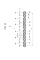
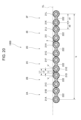
- FIG. 1 is a plan view illustrating the configuration of an optical fiber ribbon according to the first embodiment.
- FIG. 2 is a cross-sectional view illustrating the configuration of a cross section taken along line II-II in FIG. 1, viewed from the direction of the arrow.
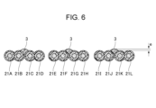
- FIG. 3 is a sectional view illustrating the configuration of a cross section taken along line III-III in FIG. 1, viewed from the direction of the arrow.
- FIG. 4 is a cross-sectional view illustrating the configuration of the sub-ribbon according to the first embodiment.
- FIG. 5 is a cross-sectional view showing the optical fiber ribbon in a state in which the unconnected portions of the optical fiber ribbon in FIG. 2 are closed in the arrangement direction.
- FIG. 6 is a cross-sectional view illustrating the configuration of a modified example of the optical fiber ribbon when the cross section taken along the line III--III in FIG. 1 is viewed from the direction of the arrow.
- FIG. 7 is a cross-sectional view illustrating the configuration of a modified example of the optical fiber ribbon, taken along the line III--III in FIG. 1 and viewed from the direction of the arrow.
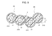
- FIG. 8 is a diagram for explaining the arrangement level difference between optical fiber cores constituting adjacent sub-ribbons.
- FIG. 9 is a diagram for explaining the arrangement level difference between optical fiber cores constituting adjacent sub-ribbons.
- FIG. 10 is a cross-sectional view of an example of the configuration of an optical fiber ribbon according to the second embodiment, viewed from the direction of the arrow, similar to the cross-section taken along line II-II in FIG.
- FIG. 11 is a cross-sectional view of an example of the configuration of an optical fiber ribbon according to the second embodiment, viewed from the direction of the arrow, similar to the cross-section taken along line III-III in FIG.
- FIG. 12 is a sectional view showing a state in which the unconnected portions of the optical fiber ribbons in FIG. 10 are closed in the arrangement direction.
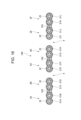
- FIG. 13 is a cross-sectional view illustrating the configuration of a sub-ribbon according to the second embodiment.
- FIG. 14 is a plan view illustrating the configuration of an optical fiber ribbon according to the third embodiment.
- FIG. 15 is a cross-sectional view illustrating the configuration of a cross section taken along line XIII-XIII in FIG. 14, viewed from the direction of the arrow.
- FIG. 16 is a cross-sectional view illustrating the configuration of a cross section taken along line XIV-XIV in FIG. 14, viewed from the direction of the arrow.
- FIG. 17 is a cross-sectional view of the optical fiber ribbon viewed from the direction of arrow XV in FIG. 14.
- FIG. 18 is a cross-sectional view of an example of the configuration of an optical fiber ribbon according to the fourth embodiment, viewed from the direction of the arrow, similar to the cross-section taken along line II-II in FIG. FIG.
- FIG. 19 is a cross-sectional view of an example of the configuration of an optical fiber ribbon according to the fourth embodiment, viewed from the direction of the arrow, similar to the cross-section taken along line III-III in FIG.
- FIG. 20 is a sectional view showing a state in which the unconnected portions of the optical fiber ribbons in FIG. 18 are closed in the arrangement direction.
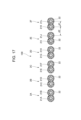
- FIG. 21 is a cross-sectional view illustrating the configuration of a sub-ribbon according to the fourth embodiment.
- FIG. 22 is a plan view illustrating the configuration of an optical fiber ribbon according to a modification of this embodiment.
- FIG. 23 is a plan view illustrating the arrangement of the connecting resin of the optical fiber ribbon according to this embodiment.
- FIG. 24 is a plan view illustrating the arrangement of the connecting resin of the optical fiber ribbon according to this embodiment.
- FIG. 25 is a plan view illustrating the arrangement of the connecting resin of the optical fiber ribbon according to this embodiment.
- FIG. 26 is a plan view illustrating the arrangement of the connecting resin of the optical fiber ribbon according to this embodiment.
- FIG. 27 is a plan view illustrating the arrangement of the connecting resin of the optical fiber ribbon according to this embodiment.
- FIG. 28 is a plan view illustrating the arrangement of the connecting resin of the optical fiber ribbon according to this embodiment.
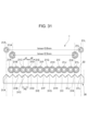
- FIG. 29 is a schematic diagram showing a state when an optical fiber ribbon is set in a fusion splicer.
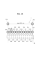
- FIG. 30 is a schematic diagram showing a state (failed example) when setting an optical fiber ribbon in a fusion splicer.
- FIG. 29 is a schematic diagram showing a state when an optical fiber ribbon is set in a fusion splicer.
- FIG. 30 is a schematic diagram showing a state (failed example)
- FIG. 31 is a schematic diagram showing a state when the optical fiber ribbon according to this embodiment is set in a fusion splicer using the sub-ribbon of the first embodiment shown in FIG.
- FIG. 32 is a schematic diagram showing a state in which the optical fiber ribbon according to this embodiment is set in a fusion splicer using the sub-ribbon of the second embodiment of FIG. 13.
- FIG. 33 is a schematic diagram showing a state in which the optical fiber ribbon according to this embodiment is set in a fusion splicer.
- FIG. 34 is a schematic diagram showing a state in which the optical fiber ribbon according to this embodiment is set in a fusion splicer.
- FIG. 35 is a schematic diagram showing a state in which the optical fiber ribbon according to this embodiment is set in a fusion splicer.
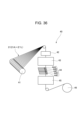
- FIG. 36 is a diagram showing the configuration of an optical fiber ribbon manufacturing apparatus according to this embodiment.
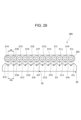
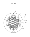
- FIG. 37 is a diagram showing the configuration of a slotless optical cable having an optical fiber ribbon according to this embodiment.
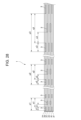
- FIG. 38 is a diagram showing the configuration of a slot-type optical cable having an optical fiber ribbon according to this embodiment.
- the present disclosure provides an optical fiber ribbon and an optical cable that can achieve both high-density storage and ease of handling during batch fusion splicing. [Effect of the invention]
- an optical fiber ribbon and an optical cable that can achieve both high-density storage and ease of handling during batch fusion splicing.
- the optical fiber ribbon of the present disclosure includes: a sub-ribbon comprising two optical fiber cores and a coating resin that covers the two optical fiber cores in the longitudinal direction; A connecting resin is provided that intermittently connects the adjacent sub-ribbons in the longitudinal direction in a state in which a plurality of the sub-ribbons are arranged in parallel.
- the flexibility of the optical fiber ribbon is improved and it can be stored in the optical cable at high density. Furthermore, since the optical fibers are integrated into each sub-ribbon, handling becomes easier when fusion splicing a plurality of optical fibers constituting an optical fiber ribbon at once.
- the two optical fibers are in continuous contact in the longitudinal direction, and the coating resin has a recess between the two optical fibers,
- the maximum thickness of the sub-ribbon is h ( ⁇ m)
- the outer diameter of the optical fiber is a ( ⁇ m)
- the thickness of the sub-ribbon in the recess of the coating resin is g ( ⁇ m)
- h ⁇ It may be a+40 ( ⁇ m) and g ⁇ 1.0a ( ⁇ m).
- the coating resin can be easily removed by rubbing the coating resin with the separating tool when separating the optical fiber core from the sub-ribbon.
- the coating resin of the sub-ribbon can be more easily removed using the separation tool.
- the distance between the centers of the opposing optical fiber coated wires of the adjacent sub-ribbons may be greater than the distance between the centers of the two optical fiber coated wires constituting the sub-ribbon.
- the thickness of the coating resin in the direction in which the sub-ribbons are arranged may be greater than the thickness of the coating resin in the thickness direction of the sub-ribbons.
- the distance between the centers of the opposing optical fiber cores of the adjacent sub-ribbons may be smaller than the distance between the centers of the two optical fiber cores constituting the sub-ribbon.
- the two optical fibers are arranged without touching each other, and a connecting portion made of a part of the coating resin is provided between the two optical fibers.
- the thickness of the connecting portion may be smaller than the outer diameter of the optical fiber.
- the number of the plurality of coated optical fibers constituting the fiber ribbon is 12, the outer diameter of each of the plurality of coated optical fibers is 200 ⁇ m, and the number of coated optical fibers of the adjacent sub-ribbons is 12.
- the distance between the centers may be greater than 260 ⁇ m and less than 360 ⁇ m.
- the number of the plurality of coated optical fibers constituting the optical fiber ribbon is 12, the outer diameter of each of the plurality of coated optical fibers is 200 ⁇ m, and the number of the optical fibers of the adjacent sub-ribbons is 12.
- the distance between the centers of the core wires may be 240 ⁇ m or less.
- the number of the plurality of coated optical fibers constituting the optical fiber ribbon is 12, the outer diameter of each of the plurality of coated optical fibers is 180 ⁇ m, and the number of the optical fibers of the adjacent sub-ribbons is 12.
- the distance between the centers of the core wires may be greater than 284 ⁇ m and less than 384 ⁇ m.
- the number of the plurality of coated optical fibers constituting the optical fiber ribbon is 12, the outer diameter of each of the plurality of coated optical fibers is 180 ⁇ m, and the number of the optical fibers of the adjacent sub-ribbons is 12.
- the distance between the centers of the core wires may be greater than 184 ⁇ m and less than 264 ⁇ m.
- the number of the plurality of coated optical fibers constituting the optical fiber ribbon is 12, the outer diameter of each of the plurality of coated optical fibers is 180 ⁇ m, and the number of the optical fibers of the adjacent sub-ribbons is 12.
- the distance between the centers of the core wires may be 216 ⁇ m or less.
- Adjacent sub-ribbons may be connected in contact with each other.
- the connecting resin when applying the connecting resin, the connecting resin tends to stay between the sub-ribbons. This improves the productivity of the optical fiber ribbon and makes it possible to reduce costs.
- the adjacent sub-ribbons may be connected in a separated state.
- the amount of resin used in the coating resin is increased.
- the amount of resin can be reduced. This improves the flexibility of the optical fiber ribbon and allows it to be packed more densely within the optical cable.
- the connecting resin may not protrude outward from the outermost circumferential position of the sub-ribbon in the thickness direction of the sub-ribbon.
- the optical fiber ribbon when the optical fiber ribbon is rolled up and stored in an optical cable at high density, the optical fiber core wire is pressed by the connecting resin, causing microbends in the optical fiber core wire and causing transmission loss. can be suppressed.
- the connecting resin may protrude outward from the outermost circumferential position of the sub-ribbon in the thickness direction of the sub-ribbon.
- the thickness of a portion of the connecting resin protruding outward from the outermost circumferential position of the sub-ribbon in the thickness direction of the sub-ribbon may be 30 ⁇ m or more and 100 ⁇ m or less.
- the protruding length of the connecting resin is 30 ⁇ m or more, the friction between the coating removal holder and the connecting resin can be sufficiently increased. If the protruding length of the connecting resin exceeds 100 ⁇ m, the optical fiber core may be pushed by the connecting resin when the optical fiber ribbon is rolled up and stored in the optical cable, causing microbend loss in the optical fiber core. growing.
- the connecting resin may be applied to an area extending beyond the vertices of the opposing optical fiber cores of the adjacent sub-ribbons in the arrangement direction.
- the contact area between the connecting resin and the coating resin becomes large, and the connecting resin becomes difficult to peel off from the coating resin.
- the connecting resin will be caught in the concave portion of the coating resin, so the adhesive force of the connecting resin will increase, and the connecting resin will It becomes difficult to peel off from the coating resin.
- the distance between the center of the optical fiber and the center of the optical fiber may be 75 ⁇ m or less. This is equivalent to setting the array step difference to 75 ⁇ m or less when the portion coated with the connecting resin is regarded as a four-core ribbon as shown in FIGS. 8 and 9.
- the arrangement level difference is large, there is a risk of scratching the surface of the glass fiber of the optical fiber when removing the coating layer of the optical fiber, the coating resin of the sub-ribbon, and the connecting resin all at once using a coating remover. There is. However, if the arrangement level difference is set to 75 ⁇ m or less, such problems will be less likely to occur, and workability during batch welding will be improved.
- the connecting resin may be formed of the same resin material as the covering resin.
- the connecting resin and the covering resin are formed of the same resin material, the adhesion is improved. As a result, unexpected separation between the connecting resin and the coating resin is less likely to occur during the process of housing the optical fiber ribbon into the optical cable.
- the connecting resin may be formed of a material containing a pigment.
- the optical fiber ribbon can be easily identified by the color of the connecting resin.
- the color of the connecting resin may be comprised of at least two colors.
- the numbers of the optical fiber ribbons can be identified by the combination of colors of the connecting resin, so the numbers of a large number of optical fiber ribbons can be identified. As a result, the efficiency of producing optical fiber ribbons can be improved and costs can be reduced.
- the connecting resin may contain air bubbles inside.
- the inclusion of air bubbles makes the connecting resin soft and stretchable, so even if the optical fiber ribbon is rolled up, the connecting resin is difficult to peel off from the sub-ribbon, and the ribbon state is easily maintained.
- the elongation at break of the connecting resin may be greater than 250% and less than 500%.
- the connecting resin will suitably follow the deformation of the optical fiber when the optical fiber ribbon is rolled up and stored in the optical cable, so that unintended damage to the connecting resin will occur. Peeling is less likely to occur. Moreover, if the elongation at break is 500% or less, when separating a plurality of coated optical fibers by hand, it is easy to peel them off moderately, and workability is improved.
- the tear strength of the connecting resin may be 0.25N or more.
- the Young's modulus of the connecting resin may be 50 MPa or less.
- the Young's modulus when the Young's modulus is 50 MPa or less, the tear strength of the connecting resin can be suppressed, and loss fluctuations at the time of intermediate post-branching can be effectively suppressed.
- the length of the connecting resin in the longitudinal direction is o
- the interval between the connecting resins formed intermittently in the longitudinal direction is p
- the shortest distance in the longitudinal direction between adjacent connecting resins in the arrangement direction of the sub-ribbons is If s, 8 ⁇ o ⁇ 60 mm, 0.1 ⁇ o/p ⁇ 0.5, and 0 ⁇ s.
- connection resin when p is an integer multiple of (o+s) from 2 to 5, the formation pattern of the connection resin is always constant, so it is easy to check the formation state of the connection resin. .
- the number of locations where the connecting resin exists between the sub-ribbons may be two or less.
- the flexibility of the optical fiber ribbon is improved, and an increase in transmission loss when accommodated in an optical cable can be suppressed.
- markings are provided on the connecting resin or the coating resin across the arrangement direction of the sub-ribbons, The markings may have a predetermined amount of deviation in the longitudinal direction between adjacent sub-ribbons.
- the markings do not form a predetermined shape pattern. This makes it easy to detect replacement of the sub-ribbon 2, and prevents connection errors during fusion splicing work.
- the predetermined amount may be greater than 0.1 mm.
- the marking deviation is larger than the manufacturing variation in the length of the optical fiber, so it is easy to identify the marking deviation. Thereby, replacement of sub-ribbons can be detected more reliably.
- the optical cable of the present disclosure includes: a cylindrical tube, A plurality of optical fiber ribbons according to any one of (1) to (33) above, which are covered by the tube in a twisted state.
- the optical cable of the present disclosure includes: a slot rod having a plurality of slot grooves; A plurality of optical fiber ribbons according to any one of (1) to (33) above, which are housed in the slot groove.
- FIG. 1 illustrates the configuration of an optical fiber ribbon 1 according to the first embodiment.
- the optical fiber ribbon 1 includes a plurality of sub-ribbons 2 and a connecting resin 3.
- the plurality of sub-ribbons 2 are arranged in parallel and are intermittently connected in the longitudinal direction by a connecting resin 3.
- connecting portions in which adjacent sub-ribbons 2 are connected by the connecting resin 3 and unconnected portions 4 in which the adjacent sub-ribbons 2 are not connected are provided intermittently in the longitudinal direction.
- FIG. 1 shows the optical fiber ribbon 1 with the non-coupling portions 4 spread out in the direction in which the sub-ribbons 2 are arranged.
- the length in the longitudinal direction of the connecting resin 3 (i.e., the connecting portion) between adjacent sub-ribbons 2 is o
- the length in the longitudinal direction of the unconnected portion 4 that is not connected by the connecting resin 3 is q
- the direction in which the sub-ribbons 2 are arranged is If the shortest distance in the longitudinal direction between adjacent connecting resins 3 is s, the optical fiber ribbon 1 is configured to satisfy 8 ⁇ o ⁇ 60 mm, 0.1 ⁇ o/p ⁇ 0.5, and 0 ⁇ s. sell.
- s is a negative value, it means that adjacent connecting resins 3 at least partially overlap in the arrangement direction.
- the optical fiber ribbon 1 includes 2N optical fiber cores 21.
- the adjacent 2n+1-th optical fiber coated wire 21 and the 2n+2-th coated optical fiber 21 are integrated over the longitudinal direction by a coating resin 22. Further, the adjacent 2n+2-th optical fiber core wire 21 and the 2n+3-th optical fiber core wire 21 are intermittently connected in the longitudinal direction by the connecting resin 3.
- N is an integer of 2 or more
- n is an integer of 0 or more.
- the sub-ribbon 2 is formed by the two optical fiber cores 21 and the coating resin 22 that covers the periphery thereof in the longitudinal direction. Further, adjacent sub-ribbons 2 are intermittently connected in the longitudinal direction by a connecting resin 3.
- the optical fiber ribbon 1 has twelve optical fiber cores 21A to 21L.
- the optical fiber cores 21A and 21B, 21C and 21D, 21E and 21F, 21G and 21H, 21I and 21J, and 21K and 21L are each integrated with the coating resin 22 while being in continuous contact with each other in the longitudinal direction.
- Six sub-ribbons 2A to 2F are formed. Further, the sub-ribbons 2A and 2B, 2B and 2C, 2C and 2D, 2D and 2E, and 2E and 2F are intermittently connected by the connecting resin 3 while in contact with each other.
- Each optical fiber core wire 21 has a glass fiber 211 and a coating layer 212.
- the glass fiber 211 is composed of, for example, a core and a cladding.
- the coating layer 212 is made of resin and covers the glass fiber 211 .
- the covering layer 212 may be composed of two covering layers instead of one, and may further include a colored layer.
- the coating resin 22 is made of a resin material such as an acrylic ultraviolet curable resin or an epoxy ultraviolet curable resin.
- the coating resin 22 is formed so that the thickness of the portion covering the upper and lower surfaces of the optical fiber coated wire 21 and the thickness of the portion covering the side surface of the optical fiber coated wire 21 are approximately equal. It is formed. Specifically, the coating resin 22 covers the optical fiber core 21 so that the thickness t1 of the sub-ribbon 2 in the thickness direction and the thickness t2 of the sub-ribbon 2 in the arrangement direction are approximately equal. Note that the thickness direction of the sub-ribbon 2 is a direction perpendicular to the arrangement direction and longitudinal direction of the sub-ribbon 2.
- the sub-ribbon 2 may be configured such that, for example, h ⁇ a+40 ( ⁇ m) and g ⁇ 1.0a ( ⁇ m). More preferably, the sub-ribbon 2 may be configured such that h ⁇ a+30 ( ⁇ m) and g ⁇ 0.9a ( ⁇ m). Note that the thickness of the sub-ribbon 2 is the size of the sub-ribbon 2 in the thickness direction.
- the connecting resin 3 is formed on one side of a plurality of sub-ribbons 2 arranged in parallel. In this example, it is formed on the upper side of the plurality of sub-ribbons 2, but it may be formed on the lower side. Furthermore, the connecting resin 3 is formed so as not to protrude outward from the outermost circumferential position of the sub-ribbon 2 in the thickness direction of the sub-ribbon 2 . Specifically, as shown in FIG. 5, the upper end of the connecting resin 3 is formed to be lower than the virtual line VL connecting the upper ends of the sub-ribbons 2.
- the connecting resin 3 is formed in a range that does not extend beyond the distance between the vertices V of the opposing optical fiber cores 21 of the adjacent sub-ribbons 2.
- the distance in the arrangement direction between the vertices V of the opposing optical fiber cores 21 of adjacent sub-ribbons 2 is L1
- the length of the connecting resin 3 in the arrangement direction is L2.
- the apex V of the optical fiber coated wire 21 is the point where the thickness of the optical fiber coated wire 21 is maximum in the thickness direction of the sub-ribbon 2, and This is the point where the virtual line intersects with the outer periphery of the optical fiber core 21 .
- the connecting resin 3 is formed of a resin material such as an acrylic ultraviolet curable resin or an epoxy ultraviolet curable resin.
- the connecting resin 3 may be formed of the same resin material as the covering resin 22.
- the elongation at break of the connecting resin 3 is greater than 250% and less than 500%.
- the tear strength of the connecting resin 3 is 0.25N or more.
- the Young's modulus of the connecting resin is 50 MPa or less.
- d2 is the distance between the centers of the opposing optical fiber coated wires 21 (2n+2nd and 2n+3rd optical fiber coated wires 21) of adjacent sub-ribbons 2.
- the optical fiber ribbon 1 is arranged such that the distance d2 between the centers of the opposing optical fiber coated wires 21 of adjacent sub-ribbons 2 is larger than the distance d1 between the centers of the two optical fiber coated wires 21 in the sub-ribbon 2. It is configured. For example, when the outer diameter of the optical fiber is 200 ⁇ m, the optical fiber is configured such that d1 is larger than 200 ⁇ m and d2 is larger than 200 ⁇ m.
- the optical fiber ribbon 1 of this embodiment since the plurality of sub-ribbons 2 are intermittently connected, the flexibility of the optical fiber ribbon 1 is improved and it can be stored in an optical cable at high density. Furthermore, since the optical fiber cores 21 are integrated into each sub-ribbon 2, when the optical fiber cores 21 constituting the optical fiber ribbon 1 are fusion spliced all at once, a plurality of unconnected optical fiber cores can be fused together. Handling becomes easier than when the wires 21 are fusion spliced. That is, the optical fiber ribbon 1 can achieve both high-density storage and ease of handling during batch fusion splicing. Furthermore, compared to the case where all adjacent optical fiber cores 21 are connected intermittently, the number of dispensers that apply the connecting resin 3 can be reduced, so the cost of equipment for manufacturing the optical fiber ribbon 1 can be reduced. can be reduced.
- the sub-ribbon 2 satisfies h ⁇ a+40 ( ⁇ m) and g ⁇ 1.0a ( ⁇ m), more preferably, h ⁇ a+30 ( ⁇ m) and g ⁇ 0.9a ( ⁇ m).
- the coating resin 22 can be easily removed by rubbing the coating resin 22 with a separating tool when separating the optical fiber core 21 from the sub-ribbon 2 .
- the efficiency of separating the optical fibers 21 into single fibers when inserting the glass fibers 211 of the optical fibers 21 into a multi-fiber connector is improved.
- the optical fiber ribbon 1 is configured such that d2 is larger than d1. This improves work efficiency when accommodating the plurality of optical fibers 21 in the groove of the fusion splicer when collectively fusion splicing the plurality of optical fibers 21 constituting the optical fiber ribbon 1. do. Particularly when the pitch of the grooves of the fusion splicer is larger than the outer diameter of the optical fiber coated wire 21, it becomes easier to accommodate the optical fiber coated wire 21 in the groove of the fusion splicer.
- adjacent sub-ribbons 2 are connected by a connecting resin 3 while in contact with each other. This makes it easier for the connecting resin 3 to remain between the sub-ribbons 2 when applying the connecting resin 3. As a result, the productivity of the optical fiber ribbon 1 is improved and costs can be reduced.
- the connecting resin 3 does not protrude outward from the outermost circumferential position of the sub-ribbon 2 in the thickness direction of the sub-ribbon 2. This prevents the possibility that when the optical fiber ribbon 1 is rolled up and stored in an optical cable at high density, the optical fiber core 21 is pushed by the connecting resin 3 and micro-bends occur in the optical fiber core 21, resulting in transmission loss. It can be suppressed.
- the connecting resin 3 when the connecting resin 3 is formed of the same resin material as the covering resin 22, the adhesion is improved. Thereby, unexpected separation between the connecting resin 3 and the coating resin 22 is less likely to occur during the process up to the time when the optical fiber ribbon 1 is housed in an optical cable.
- the connecting resin 3 when the elongation at break of the connecting resin 3 is 250% or more, the connecting resin 3 is suitable for deforming the optical fiber ribbon 1 when the optical fiber ribbon 1 is rolled up and stored in an optical cable. Since it follows, unintended peeling of the connecting resin 3 is less likely to occur. Furthermore, when the elongation at break of the connecting resin 3 is 500% or less, the connecting resin 3 can be appropriately peeled off when manually separating the plurality of optical fiber cores 21, and workability is improved.
- the tear strength of the connecting resin 3 is 0.25N or more, unintended peeling of the connecting resin 3 is unlikely to occur when the optical fiber ribbon 1 is rolled up and stored in an optical cable.
- the Young's modulus of the connecting resin 3 is 50 MPa or less, the tear strength of the connecting resin 3 is suppressed, and the loss at the time of branching after the intermediate portion where the optical fiber core 21 is taken out from the intermediate portion of the optical cable. Fluctuations can be effectively suppressed.
- the optical fiber ribbon 1 is configured to satisfy 8 ⁇ o ⁇ 60 mm, 0.1 ⁇ o/p ⁇ 0.5, and 0 ⁇ s.
- the occurrence of replacement of the sub-ribbons 2 can be suppressed, thereby improving the workability of fusion splicing. will improve.
- the unconnected portions are long to some extent and adjacent connecting resins 3 do not overlap in the arrangement direction, flexibility as a ribbon can be ensured, and an increase in transmission loss when stored in an optical cable can be suppressed.
- the connecting resin 3 does not protrude outward from the outermost circumferential position of the sub-ribbon 2 in the thickness direction of the sub-ribbon 2.
- the connecting resin 3 may protrude outward from the sub-ribbon 2 in the thickness direction of the sub-ribbon 2.
- the connecting resin 3 may be formed so that the thickness (extrusion length) e of a portion of the sub-ribbon 2 that protrudes outward from the outermost circumferential position of the sub-ribbon 2 in the thickness direction is 30 ⁇ m or more and 100 ⁇ m or less.
- the protrusion length e is the length between the position of the upper end of the connecting resin 3 in the thickness direction and the virtual line VL (see FIG. 5) connecting the upper ends of the sub-ribbons 2.
- the friction between the coating removal holder and the connecting resin 3 increases. This makes it easier to remove the coating resin 22 and the coating layer 212 together, and improves the workability of removing the coating at once.
- the protruding length of the connecting resin 3 is 30 ⁇ m or more, the friction between the coating removal holder and the connecting resin 3 can be sufficiently increased.
- the protruding length of the connecting resin 3 exceeds 100 ⁇ m, the optical fiber core 21 will be pushed by the connecting resin 3 when the optical fiber ribbon 1 is rolled up and stored in an optical cable, causing a microbend in the optical fiber core 21.
- the protruding length of the connecting resin is 100 ⁇ m or less.
- the connecting resin 3 is formed in a range that does not extend beyond the distance between the apexes V of the opposing optical fiber cores 21 of the adjacent sub-ribbons 2.
- the connecting resin 3 may be formed in a range that extends beyond the vertices V of the opposing optical fiber cores 21 of adjacent sub-ribbons 2.
- the distance L2 in the arrangement direction of the connecting resin 3 is set to be 220 ⁇ m or more (L1 In contrast, L2 can be formed to be approximately 10% larger.
- the contact area between the connecting resin 3 and the covering resin 22 becomes large, and the connecting resin 3 is caught in the recess 221 of the covering resin 22, so that the adhesive force of the connecting resin 3 is increased. Become. This makes it difficult for the connecting resin 3 to peel off from the coating resin 22.
- the center positions of the optical fiber cores 21 constituting adjacent sub-ribbons 2 are aligned along the arrangement direction of the sub-ribbons 2.
- the center positions of the optical fiber cores 21 constituting adjacent sub-ribbons 2 may be configured to be shifted in the thickness direction from the arrangement direction of the sub-ribbons 2.
- the distance between the straight line connecting the centers of the optical fibers 21 at both ends of the optical fibers 21 constituting adjacent sub-ribbons 2 and the centers of the optical fibers 21 other than both ends, that is, the arrangement level difference f is preferably 75 ⁇ m or less, more preferably 50 ⁇ m or less.
- the arrangement level difference f means, for example, in the adjacent sub-ribbons 2A and 2B shown in FIG. This is the larger of the lengths of the perpendicular lines drawn from c2 and c3.
- the arrangement level difference f is large, when removing the coating layer 212 of the optical fiber core 21, the coating resin 22 of the sub-ribbon 2, and the connecting resin 3 all at once using a sheath remover, the glass fibers 211 of the optical fiber core 21 may be removed. There is a risk of scratching the surface. However, with such a configuration, such problems are less likely to occur, and workability during batch welding is improved.
- the optical fiber ribbon 10 according to the second embodiment differs in the shape of the coating resin 122 from the optical fiber ribbon 1 according to the first embodiment.
- the optical fiber ribbon 10 includes a plurality of sub-ribbons 2 (2A to 2F) and a connecting resin 3.
- the plurality of sub-ribbons 2 are arranged in parallel and are intermittently connected in the longitudinal direction by a connecting resin 3.
- Each sub-ribbon 2 is formed of two optical fiber cores 21 (21A to 21L) and a coating resin 122 that covers the periphery thereof in the longitudinal direction.
- the connecting resin 3 is formed on one side of a plurality of sub-ribbons 2 arranged in parallel.
- the connecting resin 3 is formed above the plurality of sub-ribbons 2.
- the connecting resin 3 is formed so as not to protrude outward from the outermost circumferential position of the sub-ribbon 2 in the thickness direction of the sub-ribbon 2 .
- the connecting resin 3 is formed in a range that does not extend beyond the distance between the vertices V of the opposing optical fiber cores 21 of adjacent sub-ribbons 2 .
- the optical fiber ribbon 10 is arranged such that the distance d2 between the centers of the opposing optical fiber coated wires 21 of adjacent sub-ribbons 2 is larger than the distance d1 between the centers of the two optical fiber coated wires 21 in the sub-ribbon 2. It is configured.
- the coating resin 122 is formed so that the thickness of the portion covering the side surface of the coated optical fiber 21 is greater than the thickness of the portion covering the top and bottom surfaces of the coated optical fiber 21. has been done. Specifically, the coating resin 122 covers the optical fiber core 21 such that the thickness t2 of the sub-ribbons 2 in the arrangement direction is larger than the thickness t1 of the sub-ribbons 2 in the thickness direction. For example, when the outer diameter of the optical fiber 21 is 200 ⁇ m, the thickness t1 is 5 ⁇ m, and the maximum value of the thickness t2 is 80 ⁇ m.
- the same structure as the optical fiber ribbon 1 of the first embodiment may be applied to the structure other than the thickness of the coating resin 122.
- the connecting resin 3 may be formed to protrude outward from the outermost circumferential position of the sub-ribbon 2 in the thickness direction of the sub-ribbon 2. Further, the connecting resin 3 may be applied to an area exceeding the vertices V of the opposing optical fiber cores 21 of the adjacent sub-ribbons 2 .
- the optical fiber ribbon 10 is arranged such that the center of the optical fiber coated wires 21 at both ends of the optical fiber coated wires 21 constituting the adjacent sub-ribbons 2 is
- the distance between the connected straight line and the center of the optical fiber core 21 other than both ends, that is, the arrangement level difference, may be configured to be preferably 75 ⁇ m or less, more preferably 50 ⁇ m or less.
- the optical fiber ribbon 100 according to the third embodiment differs from the optical fiber ribbon 1 according to the first embodiment in the configuration in which the sub-ribbons 2 are connected by the connecting resin 103.
- the optical fiber ribbon 100 includes a plurality of sub-ribbons 2 (2A to 2F) and a connecting resin 103.
- the plurality of sub-ribbons 2 are arranged in parallel at a certain distance and are intermittently connected in the longitudinal direction by a connecting resin 103.
- connecting portions in which adjacent sub-ribbons 2 are connected by the connecting resin 103 and unconnected portions 4 in which the adjacent sub-ribbons 2 are not connected are provided intermittently in the longitudinal direction.
- each sub-ribbon 2 is formed of two optical fiber cores 21 (21A to 21L) and a coating resin 22 that covers the periphery thereof in the longitudinal direction. .
- the connecting resin 103 is provided between adjacent sub-ribbons 2 so as to fill the gaps between the sub-ribbons 2. That is, the adjacent sub-ribbons 2 are separated from each other, and the connecting resin 103 constitutes a bridge portion that bridges between the adjacent sub-ribbons 2.
- the distance d2 between the centers of the opposing optical fiber coated wires 21 of adjacent sub-ribbons 2 is the distance d2 between the centers of the two optical fiber coated wires 21 in the sub-ribbon 2.
- the distance d1 is larger than the distance d1.
- d1 is 200 ⁇ m
- d2 is 260 ⁇ m to 360 ⁇ m.
- the amount of the coating resin 122 is increased in order to keep the distance d2 between the centers of the opposing optical fiber cores 21 of adjacent sub-ribbons 2 within an appropriate range.
- the amount of resin used for the coating resin 22 can be reduced compared to the case where the coating resin 22 is made of resin. This improves the flexibility of the optical fiber ribbon 100 and allows it to be housed more densely within the optical cable.
- the optical fiber ribbon 100 similarly to the modification of the first embodiment, has the centers of the optical fiber coated wires 21 at both ends of the optical fiber coated wires 21 constituting the adjacent sub-ribbons 2.
- the distance between the connected straight line and the center of the optical fiber core 21 other than both ends, that is, the arrangement level difference, may be preferably 75 ⁇ m or less, preferably 50 ⁇ m or less.
- the optical fiber ribbon 1000 according to the fourth embodiment is different from the optical fiber ribbon 1 according to the first embodiment in the shape of the coating resin 222 constituting the sub-ribbon 2 and the distance between the optical fiber cores 21 in the arrangement direction.
- the optical fiber ribbon 1000 includes a plurality of sub-ribbons 2 (2A to 2F) and a connecting resin 3.
- the plurality of sub-ribbons 2 are arranged in parallel and are intermittently connected in the longitudinal direction by a connecting resin 3.
- Each sub-ribbon 2 is formed of two optical fiber cores 21 (21A to 21L) and a coating resin 222 that covers the periphery thereof in the longitudinal direction.
- the connecting resin 3 is formed on one side of a plurality of sub-ribbons 2 arranged in parallel.
- the connecting resin 3 is formed above the plurality of sub-ribbons 2.
- the connecting resin 3 is formed so as not to protrude outward from the outermost circumferential position of the sub-ribbon 2 in the thickness direction of the sub-ribbon 2 .
- the connecting resin 3 is formed in a range that does not extend beyond the distance between the vertices V of the opposing optical fiber cores 21 of adjacent sub-ribbons 2 .
- the optical fiber ribbon 1000 is configured such that the distance d2 between the centers of the opposing optical fiber cores 21 of adjacent sub-ribbons 2 is smaller than the distance d1 between the centers of the two optical fiber cores 21 in the sub-ribbon 2. It is configured.
- the coating resin 222 is formed so that the thickness of the portion covering the upper and lower surfaces of the optical fiber coated wire 21 and the thickness of the portion covering the side surface of the optical fiber coated wire 21 are approximately equal. ing. Specifically, the coating resin 22 covers the optical fiber core 21 so that the thickness t1 of the sub-ribbon 2 in the thickness direction and the thickness t2 of the sub-ribbon 2 in the arrangement direction are approximately equal.
- the coating resin 222 has a connecting portion 2221 between the two optical fiber cores 21.
- the coating resin 222 is formed so that the thickness of the connecting portion 2221 is smaller than the outer diameter a of the optical fiber core 21 .
- the minimum thickness g of the connecting portion 2221 is 190 ⁇ m.
- the distance d2 between the centers of the opposing optical fiber coated wires 21 of adjacent sub-ribbons 2 is the distance between the centers of the two optical fiber coated wires 21 in the sub-ribbon 2. Since it is smaller than d1, when a plurality of optical fiber coated wires 21 constituting the optical fiber ribbon 1000 are collectively fusion spliced, it is difficult to accommodate the plurality of optical fiber coated wires 21 in the groove of the fusion splicer. Improves work efficiency.
- the optical fibers 21 are arranged without touching each other within the sub-ribbon 2, and the thickness of the connecting portion 2221 made of a part of the coating resin 222 is greater than the outer diameter a of the optical fibers 21. Since it is small, it is possible to stably produce an optical fiber ribbon 1000 in which the distance between the centers of the opposing optical fiber cores 21 of adjacent sub-ribbons 2 is small. Thereby, the manufacturability of the optical fiber ribbon 1000 can be improved and cost reduction can be realized.
- the configuration other than the shape of the coating resin 222 constituting the sub-ribbon 2 and the distance in the arrangement direction between the optical fiber cores 21 is the same as the optical fiber ribbon 1 of the first embodiment.
- a similar configuration can be applied.
- the connecting resin 3 may be formed to protrude outward from the outermost circumferential position of the sub-ribbon 2 in the thickness direction of the sub-ribbon 2. Further, the connecting resin 3 may be applied to an area exceeding the vertices V of the opposing optical fiber cores 21 of the adjacent sub-ribbons 2 .
- the optical fiber ribbon 1000 is arranged such that the center of the optical fiber coated wires 21 at both ends of the optical fiber coated wires 21 constituting the adjacent sub-ribbons 2 is
- the distance between the connected straight line and the center of the optical fiber core 21 other than both ends, that is, the arrangement level difference, may be preferably 75 ⁇ m or less, preferably 50 ⁇ m or less.
- the connecting resin 3, 103 may be formed of a material containing a pigment.
- the color of the connecting resin 3, 103 makes it easy to identify the optical fiber ribbons 1, 10, 100.
- the connecting resin 3, 103 may be formed to have a different color from the coating resin 22. Thereby, when an operator visually checks the formation state of the connecting resin 3, the connecting resin 3 can be easily identified.
- the connecting resin 3, 103 may be composed of at least two colors.
- the connecting resin 3 that connects the sub-ribbon 2A and the sub-ribbon 2B and the connecting resin 3 that connects the sub-ribbon 2B and the sub-ribbon 2C may be formed in different colors. In this way, by varying the color combinations of the plurality of connecting resins 3, 103 formed on the optical fiber ribbons 1, 10, 100, the numbers of the many optical fiber ribbons 1, 10, 100 can be identified. As a result, the efficiency of producing optical fiber ribbons can be improved and costs can be reduced.
- the connecting resin 3, 103 may contain air bubbles. Since the connecting resin 3, 103 contains air bubbles, the connecting resin 3, 103 becomes soft and stretchable, so the optical fiber ribbon 1, 10, 100 has flexibility, and the optical fiber ribbon 1, 10, 100 can be rolled up. Also, the connecting resin 3, 103 is difficult to peel off from the sub-ribbon 2, and the ribbon state is easily maintained.
- the optical fiber ribbons 1, 10, 100 may include markings on the connecting resin 3, 103 or the coating resin 22, 122 in the arrangement direction of the sub-ribbons 2. .
- the markings 5 are formed so as to have a predetermined amount of deviation u in the longitudinal direction of the optical fiber ribbon 1 between adjacent sub-ribbons 2.
- the predetermined amount is set to be greater than 0.1 mm.
- the markings 5 have a parallelogram shape obliquely inclined in the longitudinal direction of the plurality of sub-ribbons 2, and a plurality of markings 5 are provided at predetermined intervals in the longitudinal direction of the sub-ribbons 2.
- the marking 5 can be formed by printing using an inkjet printer or the like, for example.
- the markings 5 form a predetermined shape pattern. Not formed. Thereby, it is easy to detect replacement of the sub-ribbons 2, and it is possible to prevent a plurality of optical fiber cores 21 from being connected in a replaced state during fusion splicing work. Further, by setting the predetermined amount to be larger than 0.1 mm, the marking deviation is larger than the manufacturing variation in the length of the optical fiber core 21, so that the marking deviation can be easily identified. Thereby, replacement of sub-ribbons can be detected more reliably.
- the optical fiber ribbon 1 configured as described above, in the longitudinal direction, regions where three connecting resins 3 overlap in the arrangement direction and regions where two connecting resins 3 overlap in the arrangement direction appear alternately.
- the optical fiber ribbon 1 configured as described above, in the longitudinal direction, after two regions where the connecting resins 3 overlap in the arrangement direction, three consecutive regions where the connecting resins 3 do not overlap in the arrangement direction appear.
- the connecting resins 3 are arranged without overlapping in the arrangement direction but shifted by an amount s in the longitudinal direction.
- the connecting resins 3 are arranged in the arrangement direction such that adjacent connecting resins 3 partially overlap each other in the arrangement direction.
- the formation pattern of the connecting resin 3 is always constant. Thereby, when an operator visually checks the connecting resin 3 of the optical fiber ribbon 1, it is easy to confirm the formation state of the connecting resin 3.
- the values of o, p, and s may be configured to change in the longitudinal direction of the optical fiber ribbon 1. In this case, it is preferable to change the values of o, p, and s while keeping the ratio of o:s:p constant in the longitudinal direction of the optical fiber ribbon 1.
- o, p, and s may be formed to gradually increase along the longitudinal direction.
- o, p, and s may be formed so that the values increase after repeating a pattern of the same values multiple times in the longitudinal direction.
- the operation of the device for applying the connecting resin 3 can be maintained in the same state without changing the operation.
- the optical fiber ribbon 1 can be continued to be manufactured without changing the state. Thereby, loss of the optical fiber core 21 can be reduced, and cost reduction can be realized.
- the multi-core fusion splicer includes a V-groove base 30 having a plurality of (12 in this example) V-grooves 31A to 31L for arranging each optical fiber. It is provided. These V-grooves 31A to 31L are generally formed at a pitch P0 of 250 ⁇ m in accordance with the international standard for the outer diameter of optical fiber cores. In order to fusion splice a plurality of optical fibers at once, it is necessary to sequentially arrange each optical fiber into each V-groove 31A to 31L of the V-groove base 30, one by one. It is.
- FIG. 29 shows the process of fusing an optical fiber ribbon 300 in which each of the optical fiber core wires 21A to 21L has an outer diameter of 250 ⁇ m.
- the optical fibers 21A to 21L are integrated with a coating resin 322 while in contact with each other.
- the distance d3 between the centers of adjacent optical fibers is 250 ⁇ m.
- the optical fiber cores 21A to 21L are placed above the V-groove base 30 with a predetermined length of the coating resin 322 removed from their tips.
- the optical fibers 21A to 21L are arranged such that, for example, the center position 32 of the V-groove base 30 in the direction in which the V-grooves 31A to 31L are arranged in parallel coincides with the center position in the direction in which the optical fibers 21A to 21L are arranged in parallel. Ru.
- the clamp lid (not shown) of the multi-fiber fusion splicer is closed, and the optical fibers 21A to 21L are pushed down from above by the clamp lid.
- each of the optical fibers 21A to 21L is placed at the center of each V-groove 31A to 31L. , are arranged so that their centers are located. Therefore, the optical fiber cores 21A to 21L are pushed down substantially vertically and are housed one by one in the V grooves 31A to 31L, respectively.
- FIG. 30 shows the process of fusing an optical fiber ribbon 400 in which each of the optical fiber core wires 21A to 21L has an outer diameter of 200 ⁇ m.
- the optical fibers 21A to 21L are integrated with a coating resin 322 while in contact with each other.
- the distance d4 between the centers of adjacent optical fibers is 200 ⁇ m.
- the distance d4 between the centers of the optical fiber cores is formed smaller than the pitch P0 of the V-grooves 31A to 31L. Therefore, the optical fibers 21A to 21L are arranged so as to gather toward the center position 32 of the V-groove base 30. Therefore, the optical fibers 21A to 21L cannot be accommodated in the V grooves 31A to 31L in order. For example, there may be cases where the optical fibers are not accommodated in the V-grooves 31A, 31L, etc. at the ends.
- FIG. 31 shows the process of fusing the optical fiber ribbon 1 according to the first embodiment.
- the optical fiber ribbon 1 is composed of twelve optical fibers 21A to 21L having an outer diameter of 200 ⁇ m
- the distance d1 between the centers of the optical fibers constituting the sub-ribbon 2 is 200 ⁇ m.
- the distance d2 between the centers of the opposing optical fiber cores of adjacent sub-ribbons 2 is 260 ⁇ m. It is preferable that the diameter is larger than 360 ⁇ m.
- the optical fiber 21A at this time is , 21L is 2.5 mm or more and 3.0 mm or less.
- the distance d1 between the centers of adjacent optical fibers constituting the sub-ribbon 2 is formed smaller than the pitch P0 of the V-grooves
- the distance d2 between the centers of the opposing optical fiber cores is set to be larger than the pitch P0 of the V-grooves.
- the average distance between the centers of adjacent optical fibers is approximately 250 ⁇ m, so when pressed down by the clamp lid, the optical fibers 21A to 21L are moved along the groove wall of the V groove to the corresponding V groove. It is guided to the grooves 31A to 31L and accommodated in the V grooves 31A to 31L.
- the outer diameter of 200 ⁇ m may mean that the outer diameter is substantially 200 ⁇ m, and includes, for example, cases where the outer diameter is within the range of 200 ⁇ m ⁇ 12 ⁇ m (i.e., the outer diameter is within the range of 188 ⁇ m to 212 ⁇ m). .
- FIG. 32 shows the process of fusing the optical fiber ribbon 10 according to the second embodiment.
- the distance d1 between the centers of the optical fibers constituting the sub-ribbon 2 is 180 ⁇ m.
- the distance d2 between the centers of the opposing optical fiber cores of adjacent sub-ribbons 2 is as follows: It is preferably greater than 284 ⁇ m and less than 384 ⁇ m.
- the optical fiber 21A at this time is , 21L is 2.5 mm or more and 3.0 mm or less.
- the distance d1 between the centers of adjacent optical fiber cores constituting the sub-ribbon 2 is formed smaller than the pitch P0 of the V-groove, the distance between the adjacent sub-ribbons 2
- the distance d2 between the centers of the opposing optical fiber cores is set to be larger than the pitch P0 of the V-grooves.
- the average distance between the centers of adjacent optical fibers is approximately 250 ⁇ m, so when pressed down by the clamp lid, the optical fibers 21A to 21L are moved along the groove wall of the V groove to the corresponding V groove. It is guided to the grooves 31A to 31L and accommodated in the V grooves 31A to 31L.
- the outer diameter of 180 ⁇ m may mean that the outer diameter is substantially 180 ⁇ m, and includes, for example, cases where the outer diameter is within the range of 180 ⁇ m ⁇ 10 ⁇ m (i.e., the outer diameter is within the range of 170 ⁇ m to 190 ⁇ m). .
- FIG. 33 shows a fusion splicing process in which an optical fiber ribbon 1 having 12 optical fiber cores 21A to 21L each having an outer diameter of 200 ⁇ m is fusion spliced using a V-groove base 30 having a V-groove with a pitch P0 of 200 ⁇ m. It shows.
- the distance d1 between the centers of the optical fibers constituting the sub-ribbon 2 is 200 ⁇ m.
- the distance d2 between the centers of the opposing optical fiber cores of adjacent sub-ribbons 2 is preferably 200 ⁇ m or more and 240 ⁇ m or less.
- the distance b between the centers of the optical fibers 21A and 21L at both ends is 2.4 mm or less.
- optical fiber ribbon 1 having such a structure, when performing batch fusion splicing using the V-groove base 30 having V-grooves with a pitch P0 of 200 ⁇ m, all the optical fibers 21A to 21L are connected to the V-groove 31A. ⁇ 31L can be easily inserted, improving the workability of fusion splicing.
- FIG. 34 shows an optical fiber ribbon 1 having 12 optical fiber cores with an outer diameter of 180 ⁇ m.
- the distance d1 between the centers of the optical fibers constituting the sub-ribbon 2 is 180 ⁇ m.
- the distance d2 between the centers of opposing optical fiber cores in adjacent sub-ribbons 2 is: It is preferably greater than 224 ⁇ m and less than 264 ⁇ m.
- the distance b between the centers of the optical fibers 21A to 21L at both ends of the plurality of optical fibers 21A to 21L constituting the optical fiber ribbon 1 is 2.2 mm or more and 2.4 mm or less.
- optical fiber ribbon 1 when performing batch fusion splicing using the V-groove base 30 having V-grooves with a pitch P0 of 200 ⁇ m, all the optical fiber cores 21A to 21L are connected to the V-groove 31A. ⁇ 31L can be easily inserted, improving the workability of fusion splicing.
- FIG. 35 shows a fusion splicing process in which an optical fiber ribbon 1 having 12 optical fiber cores 21A to 21L having an outer diameter of 180 ⁇ m is fusion spliced using a V-groove base 30 having a V-groove with a pitch P0 of 180 ⁇ m. It shows.
- the distance d1 between the centers of the optical fibers constituting the sub-ribbon 2 is 180 ⁇ m.
- the distance d2 between the centers of opposing optical fiber cores of adjacent sub-ribbons 2 is preferably 180 ⁇ m or more and 216 ⁇ m or less.
- the distance b between the centers of the optical fibers 21A to 21L at both ends of the plurality of optical fibers 21A to 21L constituting the optical fiber ribbon 1 becomes 2.16 mm or less.
- optical fiber ribbon 1 when performing batch fusion splicing using the V-groove base 30 having V-grooves with a pitch P0 of 180 ⁇ m, all the optical fiber cores 21A to 21L are connected to the V-groove 31A. ⁇ 31L can be easily inserted, improving the workability of fusion splicing.
- FIG. 36 illustrates the configuration of the optical fiber ribbon 1 manufacturing apparatus 40. As shown in FIG.
- the optical fiber core 21 is produced by drawing.
- the optical fiber core wire 21 is drawn so that the glass fiber 211 has an outer diameter of about 125 ⁇ m and the outer coating layer 212 has a diameter of about 200 ⁇ m.
- twelve optical fiber core wires 21A to 21L wound around the supply bobbin 41 are prepared.
- the 12 optical fiber core wires 21A to 21L unwound from the supply bobbin 41 are passed through the coating die 42 of the manufacturing device 40, with two fibers each in contact with each other.
- the coating resin 22 is applied by the coating die 42 to the outer circumferences of the two optical fibers 21A and 21B, 21C and 21D, 21E and 21F, 21G and 21H, 21I and 21J, and 21K and 21L, respectively.
- the optical fibers 21A to 21L coated with the coating resin 22 are irradiated with ultraviolet rays by the curing device 43 to cure the coating resin 22.
- the curing device 43 to cure the coating resin 22.
- six sub-ribbons 2A to 2F are formed.
- the coating device 44 intermittently coats the connecting resin 3 between the adjacent sub-ribbons 2.
- the coating device 44 includes, for example, five dispensers 44A to 44E.
- the five dispensers 44A to 44E apply the connecting resin 3 between the sub-ribbons 2A and 2B, 2B and 2C, 2C and 2D, 2D and 2E, and 2E and 2F that are in contact with each other.
- the sub-ribbons 2A to 2F coated with the connecting resin 3 are irradiated with ultraviolet rays by the curing device 45 to harden the connecting resin 3.
- an optical fiber ribbon 1 in which adjacent sub-ribbons 2 are intermittently connected in the longitudinal direction by the connecting resin 3 is completed.
- the optical fiber ribbon 1 is then wound onto the winding bobbin 46.
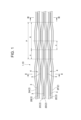
- FIG. 37 is a diagram showing an example of a slotless optical cable 50 using the optical fiber ribbon 1 of this embodiment.
- FIG. 38 is a diagram showing an example of a slot-type optical cable 60 using the optical fiber ribbon 1 of this embodiment.
- the optical cable 50 illustrated in FIG. 37 is a slotless optical cable having a cylindrical tube 51 and a plurality of optical fiber ribbons 1.
- a plurality of optical fiber ribbons 1 are covered with a tube 51 in a twisted state. Specifically, the plurality of optical fiber ribbons 1 are twisted together with each optical fiber ribbon 1 being rolled up.
- a plurality of intervening fibers (such as tensile strength fibers) 52 are accommodated in the tube 51 so as to fill the gaps between the optical fiber ribbons 1 .
- a jacket 53 is formed around the tube 51 .
- a tension member 54 and a tear string 55 are embedded in the outer cover 53.
- the intermittently connected optical fiber ribbons 1 according to the present embodiment are covered with the tube 51 in a twisted state, the transmission characteristics of the optical cable 50 are improved. Deterioration can be suppressed. Furthermore, it is possible to prevent problems from occurring when the optical fiber ribbons 1 that have been intermittently connected are taken out from the optical cable 50 and fusion spliced.
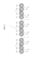
- the optical cable 60 illustrated in FIG. 38 is a slot-type optical cable that includes a slot rod 62 having a plurality of slot grooves 61 and an optical fiber ribbon 1.
- the optical cable 60 includes a slot rod 62 having a tension member 63 in the center, and the slot grooves 61 radially provided therein.
- the plurality of slot grooves 61 may be provided in, for example, a twisted shape such as a spiral shape or an SZ shape in the longitudinal direction of the optical cable 60.
- a plurality of optical fiber ribbons 1 are housed in each slot groove 61 in a twisted state.
- a jacket 64 is formed around the slot rod 62.
- the length o in the longitudinal direction of the connecting resin 3, the shortest distance s between the connecting resins 3 adjacent to each other in the arrangement direction, and the length of the unconnected portion 4 not connected by the connecting resin 3 Sample No. in which each parameter of the length q in the direction was changed. 1 to 39 were prepared.
- the transmission characteristics due to transmission loss, defects during fusion splicing of the optical fiber ribbons 1, and poor adhesion of the connecting resin 3 are explained.
- the transmission loss is considered to be related to the length o in the longitudinal direction of the connecting resin 3, the length q in the longitudinal direction of the unconnected portion 4, and the shortest distance s between the connecting resins 3 adjacent in the arrangement direction.
- sample No. where o is 70 mm. 7 the transmission loss reached a high level.
- the transmission loss was at a high level in 21-23 and 37-39.
- o/p was 0.5 or less
- s was a positive value
- the sample with low-level transmission characteristics (0.21 dB/km or less), no defects during fusion splicing, and no core wire dislocation is No. They were 2-6, 14-20, and 30-36.
- the optical fiber ribbon 1 that satisfies the conditions of 8 ⁇ o ⁇ 60 mm, 0.1 ⁇ o/p ⁇ 0.5, and 0 ⁇ s has low transmission loss and is easy to work with in fusion splicing. It turned out to be good.
- the number of coated optical fibers 21 constituting the optical fiber ribbons 1, 10, 100 is 12, but the number of coated optical fibers 21 is not limited as long as it is an even number of 4 or more.
- the number of coated optical fibers 21 included in the sub-ribbon 2 is two, but the number of coated optical fibers 21 included in the sub-ribbon 2 is not limited as long as it is two or more.
- the sub-ribbon 2 may be configured to include three, four, or more coated optical fibers 21 and a coating resin 22 that covers the periphery of the plurality of coated optical fibers 21.
- Optical fiber ribbon 2 2A to 2F: Sub-ribbon 3, 103: Connection resin 4: Non-connection part 5: Marking 21, 21A to 21L: Optical fiber core wire 211: Glass fiber 212: Covering layer 22, 122, 222, 322: Coating resin 221: Concave portion 2221: Connecting portion 30: V-groove base 31A to 31L: V-groove 32: Center position 40: Optical fiber ribbon manufacturing device 41: Supply bobbin 42: Coating die 43: Curing device 44: Coating devices 44A to 44E: Dispenser 45: Curing device 46: Winding bobbin 50: Optical cable 51: Tube 52: Interposition 53: Sheath 54: Tension member 55: Tear string 60: Optical cable 61: Slot groove 62: Slot rod 63: Tension member 64: Sheath a: Outer diameter of optical fiber core b: Distance between centers of optical fiber cores at both ends c1 to c4: Center position
Landscapes
- Physics & Mathematics (AREA)
- General Physics & Mathematics (AREA)
- Optics & Photonics (AREA)
- Optical Fibers, Optical Fiber Cores, And Optical Fiber Bundles (AREA)
- Mechanical Coupling Of Light Guides (AREA)
Abstract
Description
2本の光ファイバ心線と前記2本の光ファイバ心線の周囲を長手方向にわたって被覆する被覆樹脂とを有する、サブリボンと、
複数の前記サブリボンが並列に配置された状態で、隣り合う前記サブリボン同士を前記長手方向に間欠的に連結する連結樹脂と、を備えている。
円筒型のチューブと、
撚り合された状態で前記チューブに覆われている複数の上記の光ファイバリボンと、
を備えている。
複数のスロット溝を有するスロットロッドと、
前記スロット溝に収納されている複数の上記の光ファイバリボンと、
を備えている。
光ファイバ心線同士が間欠的に連結された光ファイバリボンにおいて、連結樹脂の割合を小さくすると、光ファイバリボンの柔軟性が向上し、光ケーブルに光ファイバリボンを高密度で収納できる。他方、光ファイバリボンを構成する複数の光ファイバ心線を他の複数の光ファイバ心線に一括で融着接続する場合、連結樹脂の割合が小さいと、取り扱いが難しくなる。
[発明の効果]
まず本開示の実施態様を列記して説明する。
2本の光ファイバ心線と前記2本の光ファイバ心線の周囲を長手方向にわたって被覆する被覆樹脂とを有する、サブリボンと、
複数の前記サブリボンが並列に配置された状態で、隣り合う前記サブリボン同士を前記長手方向に間欠的に連結する連結樹脂と、を備えている。
複数の前記サブリボンの各々において、前記2本の光ファイバ心線は前記長手方向に連続して接触しており、前記被覆樹脂は、前記2本の光ファイバ心線の間に凹部を有し、
前記サブリボンの厚さの最大値をh(μm)、前記光ファイバ心線の外径をa(μm)、前記被覆樹脂の凹部における前記サブリボンの厚さをg(μm)としたとき、h≦a+40(μm)、且つ、g≦1.0a(μm)でもよい。
前記サブリボンの厚さの最大値をh(μm)、前記光ファイバ心線の外径をa(μm)、前記被覆樹脂の凹部における前記サブリボンの厚さをg(μm)としたとき、h≦a+30(μm)、且つ、g≦0.9a(μm)でもよい。
隣り合う前記サブリボン同士の対向する前記光ファイバ心線の中心間の距離が、前記サブリボンを構成する前記2本の光ファイバ心線の中心間の距離よりも大きくてもよい。
前記被覆樹脂の前記サブリボンの配列方向の厚さが、前記被覆樹脂の前記サブリボンの厚さ方向の厚さより大きくてもよい。
隣り合う前記サブリボン同士の対向する前記光ファイバ心線の中心間の距離が、前記サブリボンを構成する前記2本の光ファイバ心線の中心間の距離よりも小さくてもよい。
前記サブリボン内で、前記2本の光ファイバ心線は互いに接することなく配置されており、前記2本の光ファイバ心線の間には、前記被覆樹脂の一部で構成された連結部を有しており、前記連結部の厚さが、前記光ファイバ心線の外径よりも小さくてもよい。
ファイバリボンを構成する複数の前記光ファイバ心線の数は12本であり、前記複数の光ファイバ心線の各々の外径は200μmであり、隣り合う前記サブリボン同士の対向する前記光ファイバ心線の中心間の距離は260μmより大きく360μm以下でもよい。
前記光ファイバリボンを構成する複数の前記光ファイバ心線の数は12本であり、前記複数の光ファイバ心線の各々の外径は200μmであり、隣り合う前記サブリボン同士の対向する前記光ファイバ心線の中心間の距離は240μm以下でもよい。
前記光ファイバリボンを構成する複数の前記光ファイバ心線の数は12本であり、前記複数の光ファイバ心線の各々の外径は180μmであり、隣り合う前記サブリボン同士の対向する前記光ファイバ心線の中心間の距離は284μmより大きく384μm以下でもよい。
前記光ファイバリボンを構成する複数の前記光ファイバ心線の数は12本であり、前記複数の光ファイバ心線の各々の外径は180μmであり、隣り合う前記サブリボン同士の対向する前記光ファイバ心線の中心間の距離は184μmより大きく264μm以下でもよい。
前記光ファイバリボンを構成する複数の前記光ファイバ心線の数は12本であり、前記複数の光ファイバ心線の各々の外径は180μmであり、隣り合う前記サブリボン同士の対向する前記光ファイバ心線の中心間の距離は216μm以下でもよい。
隣り合う前記サブリボン同士は接触した状態で連結されてもよい。
隣り合う前記サブリボン同士は離れた状態で連結されてもよい。
前記連結樹脂は、前記サブリボンの厚さ方向において、前記サブリボンの最外周位置から外側にはみ出していなくてもよい。
前記連結樹脂は、前記サブリボンの厚さ方向において、前記サブリボンの最外周位置から外側にはみ出してもよい。
前記連結樹脂の前記サブリボンの厚さ方向に、前記サブリボンの最外周位置から外側にはみ出した部分の厚さは、30μm以上100μm以下でもよい。
前記連結樹脂は、配列方向において、隣り合う前記サブリボン同士の対向する前記光ファイバ心線の頂点間を超える範囲に塗布されてもよい。
隣り合う前記サブリボンを構成する前記光ファイバ心線のうち、両端にある前記光ファイバ心線の中心をつないだ直線と、隣り合う前記サブリボンを構成する前記光ファイバ心線のうち、両端以外の位置にある前記光ファイバ心線の中心との距離が75μm以下でもよい。これは、図8、図9のように、連結樹脂が塗布された部分を4心リボンと見なした場合の、配列段差を75μm以下とすることと等価である。
隣り合う前記サブリボンを構成する前記光ファイバ心線のうち、両端にある前記光ファイバ心線の中心をつないだ直線と、隣り合う前記サブリボンを構成する前記光ファイバ心線のうち、両端以外の位置にある前記光ファイバ心線の中心との距離が50μm以下でもよい。これは、図8、図9のように、連結樹脂が塗布された部分を4心リボンと見なした場合の、配列段差を50μm以下とすることと等価である。
前記連結樹脂は、前記被覆樹脂と同じ樹脂材料により形成されてもよい。
前記連結樹脂は、顔料を含む材料により形成されてもよい。
前記連結樹脂の色は、少なくとも2色で構成されてもよい。
前記連結樹脂は、内部に気泡を含んでもよい。
前記連結樹脂の破断伸びは、250%より大きく500%以下でもよい。
前記連結樹脂の引裂強度は、0.25N以上でもよい。
前記連結樹脂のヤング率は、50MPa以下でもよい。
前記連結樹脂の前記長手方向の長さをo、前記長手方向に間欠的に形成される前記連結樹脂の間隔をp、前記サブリボンの配列方向に隣り合う前記連結樹脂間の長手方向の最短距離をsとした場合、
8≦o≦60mm、0.1≦o/p≦0.5、0<sでもよい。
前記光ファイバリボンを構成する複数の前記光ファイバ心線の数は12本であり、p=n×(o+s)であり、nは、2,3,4,5のいずれかでもよい。
前記長手方向において、前記o、s、pは変化し、且つ、o:s:pの比率は一定でもよい。
前記サブリボンの配列方向の断面において、前記サブリボン間に前記連結樹脂が存在する箇所は2か所以下でもよい。
前記サブリボンの配列方向にわたって前記連結樹脂または前記被覆樹脂上にマーキングを備えており、
前記マーキングは、隣り合う前記サブリボン間で前記長手方向に所定量のずれを有してもよい。
前記所定量は、0.1mmよりも大きくてもよい。
円筒型のチューブと、
撚り合された状態で前記チューブに覆われている、上記(1)から(33)のいずれか一つの複数の光ファイバリボンと、を備えている。
複数のスロット溝を有するスロットロッドと、
前記スロット溝に収納されている、上記(1)から(33)のいずれか一つの複数の光ファイバリボンと、を備えている。
本開示の光ファイバリボンおよび光ケーブルの具体例を、図面を参照しつつ説明する。なお、本発明はこれらの例示に限定されるものではなく、請求の範囲によって示され、請求の範囲と均等の意味及び範囲内でのすべての変更が含まれることが意図される。
まず、図1から図5を参照して、第一実施形態に係る光ファイバリボン1について説明する。
次に、図10から図13を参照して、第二実施形態に係る光ファイバリボン10について説明する。なお、第一実施形態に係る光ファイバリボン1と同様の構成については同じ符号を付しその詳細な説明を省略する。
次に、図14から図17を参照して、第三実施形態に係る光ファイバリボン100について説明する。なお、第一実施形態に係る光ファイバリボン1と同様の構成については同じ符号を付しその詳細な説明を省略する。
次に、図18から図21を参照して、第二実施形態に係る光ファイバリボン1000について説明する。なお、第一実施形態に係る光ファイバリボン1と同様の構成については同じ符号を付しその詳細な説明を省略する。
なお、上記の第一実施形態から第三実施形態において、連結樹脂3,103は、顔料を含む材料により形成されてもよい。連結樹脂3,103の色により、光ファイバリボン1,10,100の識別が容易となる。また、連結樹脂3,103は、被覆樹脂22とは異なる色になるように形成してもよい。これにより、連結樹脂3の形成状態を作業員が目視で確認する際に、連結樹脂3の識別が容易である。
次に、図23から図28を参照して、光ファイバリボン1の連結樹脂3の配置構成について説明する。なお、以下では、図1の光ファイバリボン1の連結樹脂3の配置構成を例に挙げて述べるが、この配置構成は、光ファイバリボン10,100にも適用されうる。
次に、図29から図35を参照して、光ファイバリボン1,10の光ファイバ心線21の配列ピッチについて説明する。なお、以下では、光ファイバリボン1,10を例に挙げて述べるが、この配置構成は、光ファイバリボン100にも適用されうる。
次に、図36を参照して、本実施形態に係る光ファイバリボン1の製造方法について説明する。図36は、光ファイバリボン1の製造装置40の構成を例示している。
次に、図37と図38を参照して、本実施形態に係る光ケーブルを説明する。図37は、本実施形態の光ファイバリボン1を使用したスロットレス型の光ケーブル50の一例を示す図である。図38は、本実施形態の光ファイバリボン1を使用したスロット型の光ケーブル60の一例を示す図である。
本実施形態に係る光ファイバリボン1において、連結樹脂3の長手方向の長さo、配列方向に隣り合う連結樹脂3間の最短距離s、連結樹脂3により連結されていない非連結部4の長手方向の長さqの各パラメータを変化させたサンプルNo.1~39を用意した。そして、これらの光ファイバリボン1を432心のスロットレス型の光ケーブル50に使用した場合の伝送損失による伝送特性と、光ファイバリボン1の融着接続時の不具合と、連結樹脂3の接着不良によるサブリボン2の不具合(心線ばらけ)と、を調査した。その結果を以下の表1に示す。

2,2A~2F:サブリボン
3,103:連結樹脂
4:非連結部
5:マーキング
21,21A~21L:光ファイバ心線
211:ガラスファイバ
212:被覆層
22,122,222,322:被覆樹脂
221:凹部
2221:連結部
30:V溝ベース
31A~31L:V溝
32:センター位置
40:光ファイバリボンの製造装置
41:供給ボビン
42:塗布ダイス
43:硬化装置
44:塗布装置
44A~44E:ディスペンサ
45:硬化装置
46:巻取りボビン
50:光ケーブル
51:チューブ
52:介在
53:外被
54:テンションメンバ
55:引き裂き紐
60:光ケーブル
61:スロット溝
62:スロットロッド
63:テンションメンバ
64:外被
a:光ファイバ心線の外径
b:両端の光ファイバ心線の中心間の距離
c1~c4:光ファイバ心線の中心位置
e:連結樹脂のはみだした長さ
f:隣り合うサブリボンを構成する光ファイバ心線の中心位置の厚さ方向の高さの差
g:被覆樹脂の凹部におけるサブリボンの厚さ
h:サブリボンの厚さの最大値
t1:被覆樹脂の厚さ方向の厚さ
t2:被覆樹脂の配列方向の厚さ
d1:サブリボンを構成する光ファイバ心線の中心間の距離
d2:隣り合うサブリボン同士の対向する光ファイバ心線の中心間の距離
d3:光ファイバ心線の中心間の距離
d4:光ファイバ心線の中心間の距離
L1:隣り合うサブリボン同士の対向する光ファイバ心線の頂点間の配列方向の距離
L2:連結樹脂の配列方向の距離
P0:V溝ピッチ
V:頂点
VL:仮想線
o:連結樹脂の長手方向の長さ
p:連結樹脂の長手方向に形成される間隔
q:非連結部の長手方向の長さ
s:配列方向に隣り合う連結樹脂間の最短距離
Claims (35)
- 2本の光ファイバ心線と前記2本の光ファイバ心線の周囲を長手方向にわたって被覆する被覆樹脂とを有する、サブリボンと、
複数の前記サブリボンが並列に配置された状態で、隣り合う前記サブリボン同士を前記長手方向に間欠的に連結する連結樹脂と、を備えている、光ファイバリボン。 - 複数の前記サブリボンの各々において、前記2本の光ファイバ心線は前記長手方向に連続して接触しており、前記被覆樹脂は、前記2本の光ファイバ心線の間に凹部を有し、
前記サブリボンの厚さの最大値をh(μm)、前記光ファイバ心線の外径をa(μm)、前記被覆樹脂の凹部における前記サブリボンの厚さをg(μm)としたとき、h≦a+40(μm)、且つ、g≦1.0a(μm)である、請求項1に記載の光ファイバリボン。 - 前記サブリボンの厚さの最大値をh(μm)、前記光ファイバ心線の外径をa(μm)、前記被覆樹脂の凹部における前記サブリボンの厚さをg(μm)としたとき、h≦a+30(μm)、且つ、g≦0.9a(μm)である、請求項2に記載の光ファイバリボン。
- 隣り合う前記サブリボン同士の対向する前記光ファイバ心線の中心間の距離が、前記サブリボンを構成する前記2本の光ファイバ心線の中心間の距離よりも大きい、請求項1または請求項2に記載の光ファイバリボン。
- 前記被覆樹脂の前記サブリボンの配列方向の厚さが、前記被覆樹脂の前記サブリボンの厚さ方向の厚さより大きい、請求項1または請求項2に記載の光ファイバリボン。
- 隣り合う前記サブリボン同士の対向する前記光ファイバ心線の中心間の距離が、前記サブリボンを構成する前記2本の光ファイバ心線の中心間の距離よりも小さい、請求項1に記載の光ファイバリボン。
- 前記サブリボン内で、前記2本の光ファイバ心線は互いに接することなく配置されており、前記2本の光ファイバ心線の間には、前記被覆樹脂の一部で構成された連結部を有しており、前記連結部の厚さが、前記光ファイバ心線の外径よりも小さい、請求項6に記載の光ファイバリボン。
- 前記光ファイバリボンを構成する複数の前記光ファイバ心線の数は12本であり、
前記複数の光ファイバ心線の各々の外径は200μmであり、
隣り合う前記サブリボン同士の対向する前記光ファイバ心線の中心間の距離は260μmより大きく360μm以下である、請求項1または請求項2に記載の光ファイバリボン。 - 前記光ファイバリボンを構成する複数の前記光ファイバ心線の数は12本であり、
前記複数の光ファイバ心線の各々の外径は200μmであり、
隣り合う前記サブリボン同士の対向する前記光ファイバ心線の中心間の距離は240μm以下である、請求項1または請求項2に記載の光ファイバリボン。 - 前記光ファイバリボンを構成する複数の前記光ファイバ心線の数は12本であり、
前記複数の光ファイバ心線の各々の外径は180μmであり、
隣り合う前記サブリボン同士の対向する前記光ファイバ心線の中心間の距離は284μmより大きく384μm以下である、請求項1または請求項2に記載の光ファイバリボン。 - 前記光ファイバリボンを構成する複数の前記光ファイバ心線の数は12本であり、
前記複数の光ファイバ心線の各々の外径は180μmであり、
隣り合う前記サブリボン同士の対向する前記光ファイバ心線の中心間の距離は184μmより大きく264μm以下である、請求項1または請求項2に記載の光ファイバリボン。 - 前記光ファイバリボンを構成する複数の前記光ファイバ心線の数は12本であり、
前記複数の光ファイバ心線の各々の外径は180μmであり、
隣り合う前記サブリボン同士の対向する前記光ファイバ心線の中心間の距離は216μm以下である、請求項1または請求項2に記載の光ファイバリボン。 - 隣り合う前記サブリボン同士は接触した状態で連結されている、請求項1または請求項2に記載の光ファイバリボン。
- 隣り合う前記サブリボン同士は離れた状態で連結されている、請求項1または請求項2に記載の光ファイバリボン。
- 前記連結樹脂は、前記サブリボンの厚さ方向において、前記サブリボンの最外周位置から外側にはみ出していない、請求項1または請求項2に記載の光ファイバリボン。
- 前記連結樹脂は、前記サブリボンの厚さ方向において、前記サブリボンの最外周位置から外側にはみ出している、請求項1または請求項2に記載の光ファイバリボン。
- 前記連結樹脂の前記サブリボンの厚さ方向に、前記サブリボンの最外周位置から外側にはみ出した部分の厚さは、30μm以上100μm以下である、請求項16に記載の光ファイバリボン。
- 前記連結樹脂は、配列方向において、隣り合う前記サブリボン同士の対向する前記光ファイバ心線の頂点間を超える範囲に塗布されている、請求項16に記載の光ファイバリボン。
- 隣り合う前記サブリボンを構成する前記光ファイバ心線のうち、両端にある前記光ファイバ心線の中心をつないだ直線と、隣り合う前記サブリボンを構成する前記光ファイバ心線のうち、両端以外の位置にある前記光ファイバ心線の中心との距離が75μm以下である、請求項1または請求項2に記載の光ファイバリボン。
- 隣り合う前記サブリボンを構成する前記光ファイバ心線のうち、両端にある前記光ファイバ心線の中心をつないだ直線と、隣り合う前記サブリボンを構成する前記光ファイバ心線のうち、両端以外の位置にある前記光ファイバ心線の中心との距離が50μm以下である、請求項19に記載の光ファイバリボン。
- 前記連結樹脂は、前記被覆樹脂と同じ樹脂材料により形成されている、請求項1または請求項2に記載の光ファイバリボン。
- 前記連結樹脂は、顔料を含む材料により形成されている、請求項1または請求項2に記載の光ファイバリボン。
- 前記連結樹脂の色は、少なくとも2色で構成されている、請求項22に記載の光ファイバリボン。
- 前記連結樹脂は、内部に気泡を含む、請求項1または請求項2に記載の光ファイバリボン。
- 前記連結樹脂の破断伸びは、250%より大きく500%以下である、請求項1または請求項2に記載の光ファイバリボン。
- 前記連結樹脂の引裂強度は、0.25N以上である、請求項1または請求項2に記載の光ファイバリボン。
- 前記連結樹脂のヤング率は、50MPa以下である、請求項1または請求項2に記載の光ファイバリボン。
- 前記連結樹脂の前記長手方向の長さをo、前記長手方向に間欠的に形成される前記連結樹脂の間隔をp、前記サブリボンの配列方向に隣り合う前記連結樹脂間の長手方向の最短距離をsとした場合、
8≦o≦60mm、0.1≦o/p≦0.5、0<sである、請求項1または請求項2に記載の光ファイバリボン。 - 前記光ファイバリボンを構成する複数の前記光ファイバ心線の数は12本であり、
p=n×(o+s)であり、
nは、2,3,4,5のいずれかである、請求項28に記載の光ファイバリボン。 - 前記長手方向において、前記o、s、pは変化し、且つ、o:s:pの比率は一定である、請求項28に記載の光ファイバリボン。
- 前記サブリボンの配列方向の断面において、前記サブリボン間に前記連結樹脂が存在する箇所は2か所以下である、請求項1または請求項2に記載の光ファイバリボン。
- 前記サブリボンの配列方向にわたって前記連結樹脂または前記被覆樹脂上にマーキングを備えており、
前記マーキングは、隣り合う前記サブリボン間で前記長手方向に所定量のずれを有する、請求項1または請求項2に記載の光ファイバリボン。 - 前記所定量は、0.1mmよりも大きい、請求項32に記載の光ファイバリボン。
- 円筒型のチューブと、
撚り合された状態で前記チューブに覆われている、請求項1または請求項2に記載の複数の光ファイバリボンと、を備えている、光ケーブル。 - 複数のスロット溝を有するスロットロッドと、
前記スロット溝に収納されている、請求項1または請求項2に記載の複数の光ファイバリボンと、を備えている、光ケーブル。
Priority Applications (2)
| Application Number | Priority Date | Filing Date | Title |
|---|---|---|---|
| EP23839660.0A EP4556977A4 (en) | 2022-07-13 | 2023-07-12 | FIBER OPTIC TAPE AND OPTICAL CABLE |
| JP2024533739A JPWO2024014488A1 (ja) | 2022-07-13 | 2023-07-12 |
Applications Claiming Priority (2)
| Application Number | Priority Date | Filing Date | Title |
|---|---|---|---|
| JP2022-112369 | 2022-07-13 | ||
| JP2022112369 | 2022-07-13 |
Publications (1)
| Publication Number | Publication Date |
|---|---|
| WO2024014488A1 true WO2024014488A1 (ja) | 2024-01-18 |
Family
ID=89536814
Family Applications (1)
| Application Number | Title | Priority Date | Filing Date |
|---|---|---|---|
| PCT/JP2023/025768 Ceased WO2024014488A1 (ja) | 2022-07-13 | 2023-07-12 | 光ファイバリボンおよび光ケーブル |
Country Status (3)
| Country | Link |
|---|---|
| EP (1) | EP4556977A4 (ja) |
| JP (1) | JPWO2024014488A1 (ja) |
| WO (1) | WO2024014488A1 (ja) |
Citations (14)
| Publication number | Priority date | Publication date | Assignee | Title |
|---|---|---|---|---|
| JP2004206048A (ja) | 2002-11-06 | 2004-07-22 | Sumitomo Electric Ind Ltd | 光ファイバテープ心線及びその製造方法 |
| JP2012208310A (ja) | 2011-03-30 | 2012-10-25 | Sumitomo Electric Ind Ltd | 光ファイバテープ心線の製造装置および製造方法 |
| JP2017032955A (ja) | 2015-08-06 | 2017-02-09 | 住友電気工業株式会社 | 光ファイバテープ心線、光ファイバケーブルおよび光ファイバコード |
| JP2017062431A (ja) | 2015-09-25 | 2017-03-30 | 住友電気工業株式会社 | 光ファイバテープ心線 |
| JP2017125932A (ja) | 2016-01-13 | 2017-07-20 | 住友電気工業株式会社 | 間欠連結型光ファイバテープ心線および光ケーブル |
| JP2017134360A (ja) | 2016-01-29 | 2017-08-03 | 住友電気工業株式会社 | 光ファイバテープ心線および光ケーブル |
| WO2018105424A1 (ja) * | 2016-12-06 | 2018-06-14 | 住友電気工業株式会社 | 間欠連結型光ファイバテープ心線、その製造方法、光ファイバケーブルおよび光ファイバコード |
| JP2019066802A (ja) | 2017-10-05 | 2019-04-25 | 株式会社フジクラ | 間欠連結型光ファイバテープ、及び、間欠連結型光ファイバテープの製造方法 |
| CN111175887A (zh) * | 2020-02-13 | 2020-05-19 | 江苏亨通光电股份有限公司 | 光纤带、光缆以及光纤带的制造方法 |
| JP2020204687A (ja) | 2019-06-17 | 2020-12-24 | 住友電気工業株式会社 | 光ファイバテープ心線、光ファイバケーブルおよび光ファイバテープ心線の製造方法 |
| US10983297B2 (en) | 2017-07-11 | 2021-04-20 | Prysmian S.P.A. | Optical fiber ribbon and a method of producing the same |
| WO2022085595A1 (ja) * | 2020-10-19 | 2022-04-28 | 住友電気工業株式会社 | 光ファイバテープ心線 |
| WO2022131099A1 (ja) * | 2020-12-18 | 2022-06-23 | 住友電気工業株式会社 | 光ファイバテープ心線 |
| JP2022112369A (ja) | 2021-01-21 | 2022-08-02 | 日油株式会社 | ポリカーボネート樹脂組成物及び成形品 |
Family Cites Families (5)
| Publication number | Priority date | Publication date | Assignee | Title |
|---|---|---|---|---|
| JP5697011B2 (ja) * | 2010-02-16 | 2015-04-08 | 古河電気工業株式会社 | 光ファイバケーブル、及び光ファイバケーブルの形成方法 |
| JP2016075746A (ja) * | 2014-10-03 | 2016-05-12 | 住友電気工業株式会社 | 間欠型光ファイバテープ心線及びその製造方法 |
| US11500171B2 (en) * | 2018-01-15 | 2022-11-15 | Prysmian S.P.A. | Optical fiber ribbon and a method and system of producing the same |
| WO2021045201A1 (ja) * | 2019-09-05 | 2021-03-11 | 住友電気工業株式会社 | 光ファイバテープ心線、光ファイバケーブルおよびコネクタ付光ファイバコード |
| WO2021084640A1 (ja) * | 2019-10-30 | 2021-05-06 | 株式会社フジクラ | 間欠連結型光ファイバテープ、及び間欠連結型光ファイバテープの製造方法 |
-
2023
- 2023-07-12 WO PCT/JP2023/025768 patent/WO2024014488A1/ja not_active Ceased
- 2023-07-12 JP JP2024533739A patent/JPWO2024014488A1/ja active Pending
- 2023-07-12 EP EP23839660.0A patent/EP4556977A4/en active Pending
Patent Citations (14)
| Publication number | Priority date | Publication date | Assignee | Title |
|---|---|---|---|---|
| JP2004206048A (ja) | 2002-11-06 | 2004-07-22 | Sumitomo Electric Ind Ltd | 光ファイバテープ心線及びその製造方法 |
| JP2012208310A (ja) | 2011-03-30 | 2012-10-25 | Sumitomo Electric Ind Ltd | 光ファイバテープ心線の製造装置および製造方法 |
| JP2017032955A (ja) | 2015-08-06 | 2017-02-09 | 住友電気工業株式会社 | 光ファイバテープ心線、光ファイバケーブルおよび光ファイバコード |
| JP2017062431A (ja) | 2015-09-25 | 2017-03-30 | 住友電気工業株式会社 | 光ファイバテープ心線 |
| JP2017125932A (ja) | 2016-01-13 | 2017-07-20 | 住友電気工業株式会社 | 間欠連結型光ファイバテープ心線および光ケーブル |
| JP2017134360A (ja) | 2016-01-29 | 2017-08-03 | 住友電気工業株式会社 | 光ファイバテープ心線および光ケーブル |
| WO2018105424A1 (ja) * | 2016-12-06 | 2018-06-14 | 住友電気工業株式会社 | 間欠連結型光ファイバテープ心線、その製造方法、光ファイバケーブルおよび光ファイバコード |
| US10983297B2 (en) | 2017-07-11 | 2021-04-20 | Prysmian S.P.A. | Optical fiber ribbon and a method of producing the same |
| JP2019066802A (ja) | 2017-10-05 | 2019-04-25 | 株式会社フジクラ | 間欠連結型光ファイバテープ、及び、間欠連結型光ファイバテープの製造方法 |
| JP2020204687A (ja) | 2019-06-17 | 2020-12-24 | 住友電気工業株式会社 | 光ファイバテープ心線、光ファイバケーブルおよび光ファイバテープ心線の製造方法 |
| CN111175887A (zh) * | 2020-02-13 | 2020-05-19 | 江苏亨通光电股份有限公司 | 光纤带、光缆以及光纤带的制造方法 |
| WO2022085595A1 (ja) * | 2020-10-19 | 2022-04-28 | 住友電気工業株式会社 | 光ファイバテープ心線 |
| WO2022131099A1 (ja) * | 2020-12-18 | 2022-06-23 | 住友電気工業株式会社 | 光ファイバテープ心線 |
| JP2022112369A (ja) | 2021-01-21 | 2022-08-02 | 日油株式会社 | ポリカーボネート樹脂組成物及び成形品 |
Non-Patent Citations (1)
| Title |
|---|
| See also references of EP4556977A4 |
Also Published As
| Publication number | Publication date |
|---|---|
| JPWO2024014488A1 (ja) | 2024-01-18 |
| EP4556977A1 (en) | 2025-05-21 |
| EP4556977A4 (en) | 2025-10-29 |
Similar Documents
| Publication | Publication Date | Title |
|---|---|---|
| US10310202B2 (en) | Rollable optical fiber ribbon | |
| JP7052727B2 (ja) | 間欠連結型光ファイバテープ心線、その製造方法、光ファイバケーブルおよび光ファイバコード | |
| JP6663911B2 (ja) | ルースチューブ、ルースチューブ型光ファイバケーブル、ルースチューブの製造方法、及び、複数の光ファイバの集線方法 | |
| EP3422062A1 (en) | Intermittent connection type optical fiber ribbon, manufacturing method for intermittent connection type optical fiber ribbon, optical fiber cable and optical fiber cord | |
| EP3025174B1 (en) | Fiber optic ribbon | |
| JP6362302B2 (ja) | 光ファイバテープ心線及び光ケーブル | |
| CN102681119A (zh) | 光纤缆线以及光纤带 | |
| JP7188932B2 (ja) | 光ファイバテープ心線、光ファイバケーブル、および光ファイバテープ心線の融着接続方法 | |
| JP7120248B2 (ja) | 光ファイバユニットおよび光ファイバケーブル | |
| WO2011043324A1 (ja) | 光ファイバケーブル | |
| US11415769B2 (en) | Intermittent connection-type optical fiber tape core wire, optical fiber cable, and method for manufacturing intermittent connection-type optical fiber tape core wire | |
| JP2011232733A (ja) | 光ファイバテープ心線、光ファイバケーブル、及び光ファイバテープ心線の製造方法 | |
| EP0953858A1 (en) | Optical fiber ribbon and optical fiber ribbon cable | |
| JP2013109172A (ja) | 光ファイバユニット及び光ケーブル | |
| CN110140072A (zh) | 高密度、低弯曲损耗光纤带电缆 | |
| WO2021045201A1 (ja) | 光ファイバテープ心線、光ファイバケーブルおよびコネクタ付光ファイバコード | |
| WO2024014488A1 (ja) | 光ファイバリボンおよび光ケーブル | |
| JP5721686B2 (ja) | 光ファイバテープ心線及び光ファイバケーブル | |
| JP7567192B2 (ja) | 光ファイバユニットおよび光ファイバケーブル | |
| WO2005101080A1 (ja) | 光ファイバテープユニット及び光ファイバケーブル | |
| WO2022054940A1 (ja) | 光ファイバテープ心線および光ファイバテープ心線の製造方法 | |
| JP2005070770A (ja) | 光ファイバケーブル | |
| WO2025057331A1 (ja) | 光ファイバユニット、光ファイバケーブルおよび光ファイバユニットの製造方法 | |
| WO2025115497A1 (ja) | 光ファイバユニット、光ファイバケーブルおよび光ファイバユニットの製造方法 | |
| JP2011232373A (ja) | 光ファイバテープ心線、光ファイバケーブル及び光ファイバ接続方法 |
Legal Events
| Date | Code | Title | Description |
|---|---|---|---|
| 121 | Ep: the epo has been informed by wipo that ep was designated in this application |
Ref document number: 23839660 Country of ref document: EP Kind code of ref document: A1 |
|
| WWE | Wipo information: entry into national phase |
Ref document number: 2024533739 Country of ref document: JP |
|
| WWE | Wipo information: entry into national phase |
Ref document number: 2023839660 Country of ref document: EP |
|
| NENP | Non-entry into the national phase |
Ref country code: DE |
|
| ENP | Entry into the national phase |
Ref document number: 2023839660 Country of ref document: EP Effective date: 20250213 |
|
| WWP | Wipo information: published in national office |
Ref document number: 2023839660 Country of ref document: EP |