WO2024018731A1 - 合剤シートの成形装置および成形方法 - Google Patents
合剤シートの成形装置および成形方法 Download PDFInfo
- Publication number
- WO2024018731A1 WO2024018731A1 PCT/JP2023/017780 JP2023017780W WO2024018731A1 WO 2024018731 A1 WO2024018731 A1 WO 2024018731A1 JP 2023017780 W JP2023017780 W JP 2023017780W WO 2024018731 A1 WO2024018731 A1 WO 2024018731A1
- Authority
- WO
- WIPO (PCT)
- Prior art keywords
- mixture sheet
- mixture
- roll
- removal pad
- sheet
- Prior art date
- Legal status (The legal status is an assumption and is not a legal conclusion. Google has not performed a legal analysis and makes no representation as to the accuracy of the status listed.)
- Ceased
Links
Images


Classifications
-
- B—PERFORMING OPERATIONS; TRANSPORTING
- B26—HAND CUTTING TOOLS; CUTTING; SEVERING
- B26F—PERFORATING; PUNCHING; CUTTING-OUT; STAMPING-OUT; SEVERING BY MEANS OTHER THAN CUTTING
- B26F1/00—Perforating; Punching; Cutting-out; Stamping-out; Apparatus therefor
- B26F1/38—Cutting-out; Stamping-out
-
- B—PERFORMING OPERATIONS; TRANSPORTING
- B26—HAND CUTTING TOOLS; CUTTING; SEVERING
- B26F—PERFORATING; PUNCHING; CUTTING-OUT; STAMPING-OUT; SEVERING BY MEANS OTHER THAN CUTTING
- B26F1/00—Perforating; Punching; Cutting-out; Stamping-out; Apparatus therefor
- B26F1/38—Cutting-out; Stamping-out
- B26F1/44—Cutters therefor; Dies therefor
-
- H—ELECTRICITY
- H01—ELECTRIC ELEMENTS
- H01G—CAPACITORS; CAPACITORS, RECTIFIERS, DETECTORS, SWITCHING DEVICES, LIGHT-SENSITIVE OR TEMPERATURE-SENSITIVE DEVICES OF THE ELECTROLYTIC TYPE
- H01G11/00—Hybrid capacitors, i.e. capacitors having different positive and negative electrodes; Electric double-layer [EDL] capacitors; Processes for the manufacture thereof or of parts thereof
- H01G11/84—Processes for the manufacture of hybrid or EDL capacitors, or components thereof
- H01G11/86—Processes for the manufacture of hybrid or EDL capacitors, or components thereof specially adapted for electrodes
-
- H—ELECTRICITY
- H01—ELECTRIC ELEMENTS
- H01G—CAPACITORS; CAPACITORS, RECTIFIERS, DETECTORS, SWITCHING DEVICES, LIGHT-SENSITIVE OR TEMPERATURE-SENSITIVE DEVICES OF THE ELECTROLYTIC TYPE
- H01G13/00—Apparatus specially adapted for manufacturing capacitors; Processes specially adapted for manufacturing capacitors not provided for in groups H01G4/00 - H01G11/00
-
- H—ELECTRICITY
- H01—ELECTRIC ELEMENTS
- H01M—PROCESSES OR MEANS, e.g. BATTERIES, FOR THE DIRECT CONVERSION OF CHEMICAL ENERGY INTO ELECTRICAL ENERGY
- H01M4/00—Electrodes
- H01M4/02—Electrodes composed of, or comprising, active material
- H01M4/04—Processes of manufacture in general
- H01M4/043—Processes of manufacture in general involving compressing or compaction
- H01M4/0433—Molding
-
- H—ELECTRICITY
- H01—ELECTRIC ELEMENTS
- H01M—PROCESSES OR MEANS, e.g. BATTERIES, FOR THE DIRECT CONVERSION OF CHEMICAL ENERGY INTO ELECTRICAL ENERGY
- H01M4/00—Electrodes
- H01M4/02—Electrodes composed of, or comprising, active material
- H01M4/13—Electrodes for accumulators with non-aqueous electrolyte, e.g. for lithium-accumulators; Processes of manufacture thereof
- H01M4/139—Processes of manufacture
-
- H—ELECTRICITY
- H01—ELECTRIC ELEMENTS
- H01M—PROCESSES OR MEANS, e.g. BATTERIES, FOR THE DIRECT CONVERSION OF CHEMICAL ENERGY INTO ELECTRICAL ENERGY
- H01M4/00—Electrodes
- H01M4/02—Electrodes composed of, or comprising, active material
- H01M4/04—Processes of manufacture in general
- H01M4/0402—Methods of deposition of the material
- H01M4/0404—Methods of deposition of the material by coating on electrode collectors
-
- Y—GENERAL TAGGING OF NEW TECHNOLOGICAL DEVELOPMENTS; GENERAL TAGGING OF CROSS-SECTIONAL TECHNOLOGIES SPANNING OVER SEVERAL SECTIONS OF THE IPC; TECHNICAL SUBJECTS COVERED BY FORMER USPC CROSS-REFERENCE ART COLLECTIONS [XRACs] AND DIGESTS
- Y02—TECHNOLOGIES OR APPLICATIONS FOR MITIGATION OR ADAPTATION AGAINST CLIMATE CHANGE
- Y02E—REDUCTION OF GREENHOUSE GAS [GHG] EMISSIONS, RELATED TO ENERGY GENERATION, TRANSMISSION OR DISTRIBUTION
- Y02E60/00—Enabling technologies; Technologies with a potential or indirect contribution to GHG emissions mitigation
- Y02E60/10—Energy storage using batteries
Definitions
- the present disclosure relates to a molding device and a molding method for a mixture sheet.
- Patent Document 1 describes an apparatus that supplies granules to a gap between a pair of compression rolls, compresses them into a sheet to form a coating film, and laminates this coating film on a base material.
- This device is equipped with a stepped roll having blades on its circumferential surface, and a portion of the coating film is removed by the stepped roll.
- Patent Document 1 describes that this apparatus manufactures a functional sheet used for power storage devices such as secondary batteries and capacitors.
- a current collector plate is exemplified as a base material
- an electrode mixture is exemplified as a paint.
- an exposed portion of the current collector plate can be formed by removing a portion of the electrode mixture sheet. This exposed portion can be used as a connection portion of a current collection lead, etc.
- the present disclosure has been made in view of these circumstances, and its purpose is to provide a technology for increasing the capacity of a power storage device.
- An embodiment of the present disclosure is a mixture sheet forming apparatus.
- This device has a support roll that supports a mixture sheet made of a dry electrode mixture on its circumferential surface, a frame-shaped cutting jig, and a removal pad placed within the frame of the cutting jig on its circumferential surface. and a forming roll whose circumferential surface faces the circumferential surface of the support roll at a predetermined interval and rotates together with the support roll.
- the forming roll presses a cutting jig against the mixture sheet to partially cut the mixture sheet, attaches the cut portion to the surface of the removal pad, and separates it from the mixture sheet.
- Another aspect of the present disclosure is a method for forming a mixture sheet.
- a mixture sheet made of a dry electrode mixture is supported on the circumferential surface of a support roll, and a frame-shaped cutting jig and a removal pad placed within the frame of the cutting jig are provided on the circumferential surface.
- a forming roll whose circumferential surface faces the circumferential surface of the support roll at a predetermined distance is rotated together with the support roll, and a cutting jig is pressed against the mixture sheet to partially cut the mixture sheet, This involves attaching the cut portion to the surface of the removal pad and pulling it away from the mixture sheet.
- FIG. 1 is a schematic diagram of a mixture sheet forming apparatus according to an embodiment.
- FIG. 3 is an exploded perspective view of the molding unit. It is a sectional view of a molding unit.
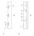
- FIG. 4(A) is a plan view of the electrode sheet.
- FIG. 4(B) is a cross-sectional view taken along line AA in FIG. 4(A).
- FIG. 5(A) is a plan view of an electrode sheet to which current collection leads are joined.
- FIG. 5(B) is an enlarged sectional view of the window portion.
- FIG. 1 is a schematic diagram of a forming apparatus 1 for a mixture sheet 6 according to an embodiment.
- the forming apparatus 1 for forming the mixture sheet 6 includes a support roll 2 and a forming roll 4.
- the support roll 2 supports the mixture sheet 6 on its peripheral surface 2a.
- the mixture sheet 6, as an example, has a long strip shape in the transport direction, and is laminated on a current collector plate and then separated into a plurality of electrode plates for use in power storage devices such as secondary batteries and capacitors.
- the mixture sheet 6 is formed, for example, as follows. That is, powder of the dry electrode mixture, which is a raw material for the mixture sheet 6, is supplied from a known storage part such as a hopper to the gap between the pair of compression rolls. The pair of compression rolls rotate in opposite directions and compress the dry electrode mixture supplied into the gap into a sheet. As a result, the mixture sheet 6 is formed.
- the mixture sheet 6 is continuously fed out from the gap between the pair of compression rolls.
- the support roll 2 is located on the downstream side of the pair of compression rolls, and conveys the mixture sheet 6 downstream by its own rotation while supporting the mixture sheet 6 on its peripheral surface 2a. Note that the mixture sheet 6 may be stretched during the conveyance process until it reaches a target thickness.
- the dry electrode mixture contains an electrode active material and, if necessary, a conductive agent and a binding material (binder).
- the electrode active material is lithium cobalt oxide, lithium iron phosphate, etc. for the positive electrode, and graphite, etc. for the negative electrode.
- the conductive agent is graphite, carbon black, acetylene black, or the like.
- the binder is polytetrafluoroethylene (PTFE), polyvinylidene fluoride (PVdF), or the like.
- the dry electrode mixture has a solvent content of 5% by mass or less, or 3% by mass or less, or even 0% by mass based on the total mass of the dry electrode mixture. Therefore, the drying oven for the mixture sheet 6 can be omitted. Note that the dry electrode mixture may contain a very small amount of solvent to the extent that a drying oven can be omitted.
- the posture of the forming roll 4 is determined so that the axis of rotation is parallel to the axis of rotation of the support roll 2.
- the circumferential surface 4a faces the circumferential surface 2a of the support roll 2 with a predetermined distance therebetween. Further, the forming roll 4 rotates together with the support roll 2.
- the support roll 2 and the forming roll 4 rotate in opposite directions. As an example, the support roll 2 and the forming roll 4 rotate at the same rotational speed.
- the forming roll 4 has a forming unit 7 composed of a cutting jig 8, a removal pad 10, and an elastic body 12 on its peripheral surface 4a.
- the forming roll 4 rotates together with the support roll 2 and presses the cutting jig 8 against the mixture sheet 6 supported by the support roll 2. As a result, the mixture sheet 6 is partially cut. Then, the forming roll 4 attaches the cut portion 6a of the mixture sheet 6 to the surface of the removal pad 10 and separates it from the mixture sheet 6. By removing the cut portion 6a, a through hole that penetrates the mixture sheet 6 in the thickness direction is formed in the mixture sheet 6. This through hole constitutes the window portion 6b.
- FIG. 2 is an exploded perspective view of the molding unit 7.
- FIG. 3 is a sectional view of the molding unit 7. Note that in FIG. 3, illustration of the mixture sheet 6 is omitted.
- the cutting jig 8 has a frame shape.
- the cutting jig 8 of this embodiment has a rectangular frame shape and includes a first cutting blade 14a to a fourth cutting blade 14d combined in a rectangular shape.
- the first cutting blade 14a and the second cutting blade 14b are arranged at a predetermined interval in the circumferential direction of the forming roll 4 and extend in the axial direction of the forming roll 4. In the rotation direction A of the forming roll 4, the first cutting blade 14a is located on the leading end side, and the second cutting blade 14b is located on the rear end side.
- the third cutting blade 14c and the fourth cutting blade 14d are lined up at a predetermined interval in the axial direction of the forming roll 4, and extend in the circumferential direction of the forming roll 4.
- the cutting edges of the first cutting blade 14a and the second cutting blade 14b extend linearly.
- the cutting edges of the third cutting blade 14c and the fourth cutting blade 14d extend in a curved shape parallel to the circumferential surface 4a.
- Each blade faces radially outward of the forming roll 4.
- the cutting jig 8 may have a frame shape such as a rectangle with rounded corners, a perfect circle, or an ellipse.
- the removal pad 10 is placed within the frame of the cutting jig 8. Therefore, when viewed from the radial direction of the forming roll 4, the removal pad 10 is surrounded by the first cutting blade 14a to the fourth cutting blade 14d.
- the surface 10a of the removal pad 10 facing the support roll 2 has a larger surface roughness than the peripheral surface 2a of the support roll 2.
- the arithmetic mean roughness Ra of the surface 10a is larger than the arithmetic mean roughness Ra of the peripheral surface 2a.
- the surface roughness of the surface 10a can be increased by known roughening treatment such as sandblasting.
- the elastic body 12 supports the removal pad 10.
- the elastic body 12 can be composed of a known spring, sponge, or the like.
- the elastic body 12 of this embodiment is formed of a coil spring, for example, and is arranged between the cutting jig 8 and the removal pad 10.
- the cutting jig 8 has a pedestal 16 within the frame. The end of the elastic body 12 on the cutting jig 8 side is fixed to the pedestal 16. The end of the elastic body 12 on the removal pad 10 side is fixed to the back surface of the removal pad 10.
- the elastic body 12 urges the removal pad 10 toward the cutting portion 6a by its own elastic force in a state where the removal pad 10 faces the support roll 2.
- the removal pad 10 when the removal pad 10 is separated from the support roll 2 due to the rotation of the support roll 2 and the forming roll 4, the removal pad 10 is drawn toward the forming roll 4 by its own elastic force.
- the elastic body 12 functions similarly to the popping member of a punching die.
- the removal pad 10 itself may have elasticity. In this case, the removal pad 10 also serves as the elastic body 12.
- the tip of the cutting jig 8 in the rotation direction A of the forming roll 4 protrudes from the tip of the removal pad 10 toward the support roll 2 side.
- the rear end portion of the cutting jig 8 in the rotation direction A protrudes from the rear end portion of the removal pad 10 toward the support roll 2 side. That is, the cutting edges of the first cutting blade 14a and the second cutting blade 14b each protrude toward the support roll 2 side from the surface 10a of the removal pad 10.
- the intermediate portion of the removal pad 10 in the rotation direction A protrudes from the intermediate portion of the cutting jig 8 toward the support roll 2 side.
- the surface 10a of the removal pad 10 protrudes more toward the support roll 2 than the third cutting blade 14c and the fourth cutting blade 14d.
- the surface 10a of the removal pad 10 has a curved shape with a larger curvature than the peripheral surface 4a of the forming roll 4.
- the forming unit 7 approaches the peripheral surface 2a of the support roll 2 as the forming roll 4 rotates.
- the first cutting blade 14a is pressed against the mixture sheet 6. Since the cutting jig 8 protrudes beyond the removal pad 10 at the tip in the rotation direction A, the first cutting blade 14a can be more reliably applied to the mixture sheet 6.
- the first cutting blade 14a cuts the mixture sheet 6, a starting point of the cutting portion 6a is formed.
- the surface 10a of the removal pad 10 comes into contact with the mixture sheet 6, and the surface 10a is pressed against the mixture sheet 6 by the urging force of the elastic body 12. Further, the removal pad 10 sinks into the frame of the cutting jig 8 due to the reaction force of the mixture sheet 6. Thereby, the third cutting blade 14c and the fourth cutting blade 14d are pressed against the mixture sheet 6. When the third cutting blade 14c and the fourth cutting blade 14d cut the mixture sheet 6, the cutting portion 6a extends rearward in the rotation direction A.
- the cut portion 6a is transferred onto the surface 10a of the removal pad 10 from the tip side in the rotation direction A.
- the cut portion 6a can be easily transferred to the removal pad 10. Further, by pressing the surface 10a against the cut portion 6a with the elastic body 12, the cut portion 6a can be easily transferred to the removal pad 10.
- the second cutting blade 14b is pressed against the mixture sheet 6. Since the cutting jig 8 protrudes beyond the removal pad 10 at the rear end in the rotational direction A, the second cutting blade 14b can be more reliably applied to the mixture sheet 6.
- the second cutting blade 14b cuts the mixture sheet 6, the end point of the cut portion 6a is formed. Thereby, the cut portion 6a becomes rectangular.
- the removal pad 10 separates from the peripheral surface 2a of the support roll 2.
- the cut portion 6a transferred to the removal pad 10 is separated from the mixture sheet 6.
- the removal pad 10 is pulled toward the support roll 2 via the cut portion 6a.
- the removal pad 10 is pulled toward the forming roll 4 by a force stronger than the force pulled toward the support roll 2 by the elastic body 12 . Thereby, the cut portion 6a can be separated from the mixture sheet 6 more reliably.
- the cutting jig 8 is fixed to the forming roll 4. Therefore, compared to a structure in which the cutting jig 8 is displaced in the radial direction of the forming roll 4, the structure of the forming unit 7 can be simplified. Furthermore, maintenance of the forming roll 4 becomes easier. Furthermore, in this embodiment, the window portion 6b is formed before the mixture sheet 6 is laminated on the current collector plate. This makes it possible to prevent the current collector plate from being cut out by the cutting jig 8. Therefore, it is possible to improve the quality of the power storage device.
- the cut portion 6a separated from the mixture sheet 6 is peeled off and removed from the removal pad 10 by a peeling mechanism (not shown) at a predetermined position.
- the molding unit 7 from which the cutting portion 6a has been removed advances to a position facing the support roll 2 again by the rotation of the molding roll 4, and is subjected to the cutting process of the mixture sheet 6.
- a plurality of windows 6b are formed in the mixture sheet 6 at predetermined intervals in the transport direction.
- each window portion 6b is arranged at the center of the mixture sheet 6 in the width direction (direction perpendicular to the conveyance direction).
- the forming roll 4 shown in FIG. 1 has only one forming unit 7, the number of forming units 7 is not limited to one.
- the forming roll 4 may have a plurality of forming units 7 depending on the interval between the windows 6b formed in the mixture sheet 6. Furthermore, the interval between the window portions 6b may be adjusted by the interval between the plurality of forming units 7, or by the radius of the forming roll 4.
- FIG. 4(A) is a plan view of the electrode sheet 20.
- FIG. 4(B) is a cross-sectional view taken along line AA in FIG. 4(A).
- the mixture sheet 6 having the window portion 6b is conveyed downstream by the support roll 2.
- the mixture sheet 6 is then laminated on the surface of the current collector plate 18 to obtain the electrode sheet 20.
- the electrode sheet 20 is a continuous body of a plurality of dry electrode plates.
- mixture sheets 6 are laminated on both sides of current collector plate 18 .
- the current collector plate 18 is made of aluminum foil or the like if it is a positive electrode, and is made of copper foil or the like if it is a negative electrode.
- the current collector plate 18 is exposed at the window portion 6b.
- each window portion 6b is surrounded by a dry electrode mixture. Therefore, the current collector plate 18 is exposed in spots.
- the exposed portion of the current collector plate 18, that is, the portion to which the electrode mixture is not applied extends across the entire width of the electrode sheet.
- the exposed portion of the current collector plate 18 extends only in a part of the electrode sheet 20 in the width direction. Therefore, the amount of dry electrode mixture on each electrode plate can be increased. Therefore, it is possible to increase the capacity of the power storage device. Furthermore, since the exposed portion of the current collector plate 18 can be made smaller, the safety of the power storage device can also be improved.
- FIG. 5(A) is a plan view of the electrode sheet 20 to which the current collection leads 22 are bonded.
- FIG. 5(B) is an enlarged sectional view of the window portion 6b. Note that the cross section shown in FIG. 5(B) is a cross section of the electrode sheet 20 perpendicular to the extending direction of the current collector plate 18 and the mixture sheet 6, in other words, the normal line of the current collector plate 18 and the mixture sheet 6. It is a cross section parallel to . Further, in FIG. 5(B), illustration of one of the mixture sheets 6 is omitted.
- the electrode sheet 20 is cut at the center in the width direction and divided into two, as shown in FIG. 5(A). As a result, each window portion 6b is also divided into two. As a result, each rectangular window portion 6b is surrounded on three sides by the dry electrode mixture. Then, a current collecting lead 22 (current collecting tab) is joined by welding or the like to a portion of the current collecting plate 18 exposed from each divided window portion 6b. The exposed portion of the current collector plate 18 to which the current collector leads 22 are bonded is covered with an insulating protective tape (not shown). Thereafter, the electrode sheet 20 is cut between adjacent current collecting leads 22 to separate into a plurality of dry electrode plates.
- the side wall 6c (the side surface connecting the two main surfaces) of the mixture sheet 6 at the window portion 6b.
- the angle ⁇ 1 formed with the surface 18a of the current collector plate 18 is 75° or more and 105° or less.
- the angle ⁇ 1 is 75° to 105° around the entire circumference of the window portion 6b.
- the angle ⁇ 1 is 85° or more and 95° or less.
- the angle ⁇ 1 between the side wall 6c and the surface 18a of the current collecting plate 18 is approximately a right angle of 75° or more and 105° or less.
- poor bonding between the current collecting plate 18 and the current collecting lead 22 due to interference of the dry electrode mixture can be prevented. It can be easily suppressed. Further, contact between the current collection lead 22 and the dry electrode mixture can be easily suppressed. With these, it is possible to improve the quality of the power storage device. In particular, if the unapplied portions of the dry electrode mixture become spots, it becomes difficult to join the current collecting leads 22. Therefore, the effect of improving the quality of the power storage device by making the angle ⁇ 1 substantially right angle is more likely to be exhibited.
- the boundary between the uncoated area and the coated area of the wet electrode mixture may be distorted due to sagging of the wet electrode mixture.
- the edges of the applied area may become jagged.
- the separator may be damaged when the electrode plate repeatedly expands and contracts due to charging and discharging of the power storage device. Damage to the separator can cause an internal short circuit.
- the window portion 6b is formed by cutting the mixture sheet 6 made of the dry electrode mixture with the cutting jig 8. Therefore, the boundary between the uncoated part and the coated part of the dry electrode mixture is not easily distorted, and the above-mentioned angle ⁇ 1 can be maintained at a substantially right angle. Moreover, the edge of the application part is linear in accordance with the shape of the cutting blade. Therefore, damage to the separator can also be suppressed. Furthermore, since the window portion 6b is formed by cutting with the cutting jig 8, it is possible to suppress the edges of the application portion from rising in the thickness direction of the mixture sheet 6. This also suppresses damage to the separator when the electrode plate repeatedly expands and contracts due to charging and discharging of the power storage device.
- Embodiments may be specified by the items described below.
- a support roll (2) that supports a mixture sheet (6) made of a dry electrode mixture on a peripheral surface (2a); It has a frame-shaped cutting jig (8) and a removal pad (10) disposed within the frame of the cutting jig (8) on its circumferential surface (4a), and the circumferential surface (4a) is attached to the supporting roll (2).
- a forming roll (4) that faces the circumferential surface (2a) of the mold at a predetermined distance and rotates with the rotation of the support roll (2);
- the forming roll (4) partially cuts the mixture sheet (6) by pressing the cutting jig (8) against the mixture sheet (6), and removes the cut portion (6a) from the surface of the removal pad (10). (10a) and separate it from the mixture sheet (6).
- the surface (10a) of the removal pad (10) has a larger surface roughness than the peripheral surface (2a) of the support roll (2). Molding device (1) according to the first item.
- the forming roll (4) has an elastic body (12) that supports the removal pad (10).
- the molding device (1) according to the first item or the second item. [4th item]
- the tip of the cutting jig (8) in the rotation direction (A) of the forming roll (4) protrudes from the tip of the removal pad (10) toward the support roll (2)
- the rear end of the cutting jig (8) in the rotation direction (A) protrudes from the rear end of the removal pad (10) toward the support roll (2)
- the middle part of the removal pad (10) in the rotation direction (A) protrudes toward the support roll (2) from the middle part of the cutting jig (8).
- the molding device (1) according to any one of the first to third items.
- a mixture sheet (6) composed of a dry electrode mixture is supported on the peripheral surface (2a) of the support roll (2), It has a frame-shaped cutting jig (8) and a removal pad (10) disposed within the frame of the cutting jig (8) on its circumferential surface (4a), and the circumferential surface (4a) is attached to the supporting roll (2). ) is rotated together with the support roll (2), and the forming roll (4) facing the peripheral surface (2a) of the The cutting jig (8) is pressed against the mixture sheet (6) to partially cut the mixture sheet (6), and the cut portion (6a) is attached to the surface (10a) of the removal pad (10). including separating it from the mixture sheet (6); Method for forming mixture sheet (6).
- An electrode sheet (20) comprising a current collector plate (18) and a mixture sheet (6) composed of a dry electrode mixture and laminated on the surface of the current collector plate (18),
- the mixture sheet (6) has a window (6b) surrounded by the dry electrode mixture all around, and the current collector plate (18) is exposed in the window (6b).
- the side wall (6c) of the mixture sheet (6) in the window portion (6b) and the surface of the current collector plate (18) The angle ( ⁇ 1) formed with (18a) is 75° or more and 105° or less, Electrode sheet (20).
- the present disclosure can be used in a molding device and a molding method for a mixture sheet.
- Forming device 2. Support roll, 4. Forming roll, 6. Mixture sheet, 6a. Cutting section, 6b. Window section, 6c. Side wall, 8. Cutting jig, 10. Removal pad, 12. Elastic body, 18. Current collector plate. 20 Electrode sheet.
Landscapes
- Engineering & Computer Science (AREA)
- Manufacturing & Machinery (AREA)
- Power Engineering (AREA)
- Chemical & Material Sciences (AREA)
- Electrochemistry (AREA)
- Chemical Kinetics & Catalysis (AREA)
- Microelectronics & Electronic Packaging (AREA)
- General Chemical & Material Sciences (AREA)
- Life Sciences & Earth Sciences (AREA)
- Forests & Forestry (AREA)
- Mechanical Engineering (AREA)
- Materials Engineering (AREA)
- Battery Electrode And Active Subsutance (AREA)
Abstract
Description
[第1項目]
乾式電極合剤で構成される合剤シート(6)を周面(2a)で支持する支持ロール(2)と、
枠状の切断治具(8)、および切断治具(8)の枠内に配置される除去パッド(10)を周面(4a)に有し、当該周面(4a)が支持ロール(2)の周面(2a)と所定の間隔をあけて対向し、支持ロール(2)の回転とともに回転する成形ロール(4)と、を備え、
成形ロール(4)は、切断治具(8)を合剤シート(6)に押し当てて合剤シート(6)を部分的に切断し、切断部(6a)を除去パッド(10)の表面(10a)に付着させて合剤シート(6)から引き離す、
合剤シート(6)の成形装置(1)。
[第2項目]
除去パッド(10)の表面(10a)は、支持ロール(2)の周面(2a)よりも表面粗さが大きい、
第1項目に記載の成形装置(1)。
[第3項目]
成形ロール(4)は、除去パッド(10)を支持する弾性体(12)を有する、
第1項目または第2項目に記載の成形装置(1)。
[第4項目]
成形ロール(4)の回転方向(A)における切断治具(8)の先端部は、除去パッド(10)の先端部より支持ロール(2)側に突出し、
回転方向(A)における切断治具(8)の後端部は、除去パッド(10)の後端部より支持ロール(2)側に突出し、
回転方向(A)における除去パッド(10)の中間部は、切断治具(8)の中間部より支持ロール(2)側に突出する、
第1項目乃至第3項目のいずれかに記載の成形装置(1)。
[第5項目]
乾式電極合剤で構成される合剤シート(6)を支持ロール(2)の周面(2a)で支持し、
枠状の切断治具(8)、および切断治具(8)の枠内に配置される除去パッド(10)を周面(4a)に有し、当該周面(4a)が支持ロール(2)の周面(2a)と所定の間隔をあけて対向する成形ロール(4)を支持ロール(2)とともに回転させ、
切断治具(8)を合剤シート(6)に押し当てて合剤シート(6)を部分的に切断し、切断部(6a)を除去パッド(10)の表面(10a)に付着させて合剤シート(6)から引き離すことを含む、
合剤シート(6)の成形方法。
[第6項目]
集電板(18)と、乾式電極合剤で構成されて集電板(18)の表面に積層された合剤シート(6)と、を備える電極シート(20)であって、
合剤シート(6)は、全周が乾式電極合剤で囲まれた窓部(6b)を有し、窓部(6b)において集電板(18)が露出し、
集電板(18)および合剤シート(6)の延在方向と直交する断面において、窓部(6b)における合剤シート(6)の側壁(6c)と、集電板(18)の表面(18a)とのなす角度(θ1)が75°以上105°以下である、
電極シート(20)。
Claims (5)
- 乾式電極合剤で構成される合剤シートを周面で支持する支持ロールと、
枠状の切断治具、および前記切断治具の枠内に配置される除去パッドを周面に有し、当該周面が前記支持ロールの周面と所定の間隔をあけて対向し、前記支持ロールとともに回転する成形ロールと、を備え、
前記成形ロールは、前記切断治具を前記合剤シートに押し当てて前記合剤シートを部分的に切断し、切断部を前記除去パッドの表面に付着させて前記合剤シートから引き離す、
合剤シートの成形装置。 - 前記除去パッドの表面は、前記支持ロールの周面よりも表面粗さが大きい、
請求項1に記載の成形装置。 - 前記成形ロールは、前記除去パッドを支持する弾性体を有する、
請求項1または2に記載の成形装置。 - 前記成形ロールの回転方向における前記切断治具の先端部は、前記除去パッドの前記先端部より前記支持ロール側に突出し、
前記回転方向における前記切断治具の後端部は、前記除去パッドの前記後端部より前記支持ロール側に突出し、
前記回転方向における前記除去パッドの中間部は、前記切断治具の前記中間部より前記支持ロール側に突出する、
請求項1または2に記載の成形装置。 - 乾式電極合剤で構成される合剤シートを支持ロールの周面で支持し、
枠状の切断治具、および前記切断治具の枠内に配置される除去パッドを周面に有し、当該周面が前記支持ロールの周面と所定の間隔をあけて対向する成形ロールを前記支持ロールとともに回転させ、
前記切断治具を前記合剤シートに押し当てて前記合剤シートを部分的に切断し、切断部を前記除去パッドの表面に付着させて前記合剤シートから引き離すことを含む、
合剤シートの成形方法。
Priority Applications (4)
| Application Number | Priority Date | Filing Date | Title |
|---|---|---|---|
| CN202380049706.4A CN119421769A (zh) | 2022-07-19 | 2023-05-11 | 合剂片的成型装置及成型方法 |
| JP2024534942A JPWO2024018731A1 (ja) | 2022-07-19 | 2023-05-11 | |
| US18/996,307 US20260018587A1 (en) | 2022-07-19 | 2023-05-11 | Molding apparatus and molding method for compound sheet |
| EP23842663.9A EP4559645A4 (en) | 2022-07-19 | 2023-05-11 | MOLDING DEVICE AND MOLDING METHOD FOR MIXING SHEET |
Applications Claiming Priority (2)
| Application Number | Priority Date | Filing Date | Title |
|---|---|---|---|
| JP2022-114706 | 2022-07-19 | ||
| JP2022114706 | 2022-07-19 |
Publications (1)
| Publication Number | Publication Date |
|---|---|
| WO2024018731A1 true WO2024018731A1 (ja) | 2024-01-25 |
Family
ID=89617412
Family Applications (1)
| Application Number | Title | Priority Date | Filing Date |
|---|---|---|---|
| PCT/JP2023/017780 Ceased WO2024018731A1 (ja) | 2022-07-19 | 2023-05-11 | 合剤シートの成形装置および成形方法 |
Country Status (5)
| Country | Link |
|---|---|
| US (1) | US20260018587A1 (ja) |
| EP (1) | EP4559645A4 (ja) |
| JP (1) | JPWO2024018731A1 (ja) |
| CN (1) | CN119421769A (ja) |
| WO (1) | WO2024018731A1 (ja) |
Cited By (1)
| Publication number | Priority date | Publication date | Assignee | Title |
|---|---|---|---|---|
| WO2026053730A1 (ja) * | 2024-09-09 | 2026-03-12 | パナソニックIpマネジメント株式会社 | シート成形装置 |
Citations (5)
| Publication number | Priority date | Publication date | Assignee | Title |
|---|---|---|---|---|
| JPH0473499U (ja) * | 1990-11-05 | 1992-06-26 | ||
| JPH09201798A (ja) * | 1996-01-30 | 1997-08-05 | Nippon Daisuchiile Kk | 紙器打抜装置のクッション材 |
| JPH10100098A (ja) * | 1996-09-30 | 1998-04-21 | Daisou Kk | 打抜装置 |
| JP2005001012A (ja) * | 2003-06-09 | 2005-01-06 | Nippon Tungsten Co Ltd | ロータリーカッター |
| JP2013017962A (ja) | 2011-07-12 | 2013-01-31 | Panasonic Corp | 塗布装置 |
Family Cites Families (2)
| Publication number | Priority date | Publication date | Assignee | Title |
|---|---|---|---|---|
| JP2001269896A (ja) * | 2000-03-23 | 2001-10-02 | Nippon Tungsten Co Ltd | ダイカットロールおよびそれを用いる裁断装置 |
| JP6455498B2 (ja) * | 2016-11-16 | 2019-01-23 | トヨタ自動車株式会社 | 電極板製造装置、正極板の製造方法及び負極板の製造方法 |
-
2023
- 2023-05-11 CN CN202380049706.4A patent/CN119421769A/zh active Pending
- 2023-05-11 JP JP2024534942A patent/JPWO2024018731A1/ja active Pending
- 2023-05-11 US US18/996,307 patent/US20260018587A1/en active Pending
- 2023-05-11 WO PCT/JP2023/017780 patent/WO2024018731A1/ja not_active Ceased
- 2023-05-11 EP EP23842663.9A patent/EP4559645A4/en active Pending
Patent Citations (5)
| Publication number | Priority date | Publication date | Assignee | Title |
|---|---|---|---|---|
| JPH0473499U (ja) * | 1990-11-05 | 1992-06-26 | ||
| JPH09201798A (ja) * | 1996-01-30 | 1997-08-05 | Nippon Daisuchiile Kk | 紙器打抜装置のクッション材 |
| JPH10100098A (ja) * | 1996-09-30 | 1998-04-21 | Daisou Kk | 打抜装置 |
| JP2005001012A (ja) * | 2003-06-09 | 2005-01-06 | Nippon Tungsten Co Ltd | ロータリーカッター |
| JP2013017962A (ja) | 2011-07-12 | 2013-01-31 | Panasonic Corp | 塗布装置 |
Non-Patent Citations (1)
| Title |
|---|
| See also references of EP4559645A4 |
Cited By (1)
| Publication number | Priority date | Publication date | Assignee | Title |
|---|---|---|---|---|
| WO2026053730A1 (ja) * | 2024-09-09 | 2026-03-12 | パナソニックIpマネジメント株式会社 | シート成形装置 |
Also Published As
| Publication number | Publication date |
|---|---|
| EP4559645A1 (en) | 2025-05-28 |
| EP4559645A4 (en) | 2025-10-08 |
| US20260018587A1 (en) | 2026-01-15 |
| JPWO2024018731A1 (ja) | 2024-01-25 |
| CN119421769A (zh) | 2025-02-11 |
Similar Documents
| Publication | Publication Date | Title |
|---|---|---|
| JP7540630B2 (ja) | 超音波切削機を含む電極組立体製造装置及びこれを用いた電極組立体製造方法 | |
| CN103891024B (zh) | 具备螺旋电极体的电池及其制造方法 | |
| CN113013377A (zh) | 电池 | |
| JP2005190787A (ja) | 非水電解質二次電池用電極板およびその製造方法 | |
| CN217451483U (zh) | 辊压装置、复合极片、电池单体以及用电装置 | |
| JP7320011B2 (ja) | ロールプレス装置及び圧密化済み帯状電極板の製造方法 | |
| JP2005183181A (ja) | 非水電解質二次電池用電極板およびその製造方法 | |
| JP2018026334A (ja) | 蓄電装置の電極、電極の製造装置及び電極の製造方法 | |
| WO2024018731A1 (ja) | 合剤シートの成形装置および成形方法 | |
| JP2017196669A (ja) | 電極製造設備 | |
| JP2017132019A (ja) | 電極製造装置 | |
| WO2024018732A1 (ja) | 電極シート | |
| JP5550091B2 (ja) | 非水電解質二次電池用電極の製造方法およびそれを用いた非水電解質二次電池 | |
| JP2018073658A (ja) | 電極製造装置 | |
| JP4166973B2 (ja) | 電池用電極製造用プレス装置及び電池用電極の製造方法 | |
| US20190074550A1 (en) | Electrode assembly for secondary battery and method for producing electrode assembly for secondary battery | |
| JP6736953B2 (ja) | 電極の製造方法及びロータリーダイカッタ | |
| JP2020196080A (ja) | ロータリーダイカット装置 | |
| JPH11167916A (ja) | 電池用電極板の製造方法 | |
| CN214505544U (zh) | 一种电池极片制备装置 | |
| JP2001043848A (ja) | ポリマーバッテリーの製造方法および剥離装置 | |
| CN220774413U (zh) | 一种电极极片及电池卷芯、用电装置 | |
| CN117103748A (zh) | 制痕装置、极片生产系统及极片制痕方法 | |
| JP7796326B2 (ja) | 切断装置および切断方法 | |
| EP4316757B1 (en) | CUTTING DEVICE AND CUTTING PROCESS |
Legal Events
| Date | Code | Title | Description |
|---|---|---|---|
| 121 | Ep: the epo has been informed by wipo that ep was designated in this application |
Ref document number: 23842663 Country of ref document: EP Kind code of ref document: A1 |
|
| ENP | Entry into the national phase |
Ref document number: 2024534942 Country of ref document: JP Kind code of ref document: A |
|
| WWE | Wipo information: entry into national phase |
Ref document number: 202380049706.4 Country of ref document: CN |
|
| WWE | Wipo information: entry into national phase |
Ref document number: 18996307 Country of ref document: US |
|
| WWP | Wipo information: published in national office |
Ref document number: 202380049706.4 Country of ref document: CN |
|
| WWE | Wipo information: entry into national phase |
Ref document number: 2023842663 Country of ref document: EP |
|
| NENP | Non-entry into the national phase |
Ref country code: DE |
|
| ENP | Entry into the national phase |
Ref document number: 2023842663 Country of ref document: EP Effective date: 20250219 |
|
| WWP | Wipo information: published in national office |
Ref document number: 2023842663 Country of ref document: EP |
|
| WWP | Wipo information: published in national office |
Ref document number: 18996307 Country of ref document: US |