WO2024018766A1 - 自律移動体制御システム、自律移動体、および制御装置 - Google Patents
自律移動体制御システム、自律移動体、および制御装置 Download PDFInfo
- Publication number
- WO2024018766A1 WO2024018766A1 PCT/JP2023/020680 JP2023020680W WO2024018766A1 WO 2024018766 A1 WO2024018766 A1 WO 2024018766A1 JP 2023020680 W JP2023020680 W JP 2023020680W WO 2024018766 A1 WO2024018766 A1 WO 2024018766A1
- Authority
- WO
- WIPO (PCT)
- Prior art keywords
- autonomous mobile
- control
- mobile body
- control signal
- bodies
- Prior art date
- Legal status (The legal status is an assumption and is not a legal conclusion. Google has not performed a legal analysis and makes no representation as to the accuracy of the status listed.)
- Ceased
Links
Images



Classifications
-
- G—PHYSICS
- G05—CONTROLLING; REGULATING
- G05D—SYSTEMS FOR CONTROLLING OR REGULATING NON-ELECTRIC VARIABLES
- G05D1/00—Control of position, course, altitude or attitude of land, water, air or space vehicles, e.g. using automatic pilots
- G05D1/60—Intended control result
- G05D1/69—Coordinated control of the position or course of two or more vehicles
- G05D1/698—Control allocation
- G05D1/6987—Control allocation by centralised control off-board any of the vehicles
-
- G—PHYSICS
- G05—CONTROLLING; REGULATING
- G05D—SYSTEMS FOR CONTROLLING OR REGULATING NON-ELECTRIC VARIABLES
- G05D1/00—Control of position, course, altitude or attitude of land, water, air or space vehicles, e.g. using automatic pilots
- G05D1/60—Intended control result
- G05D1/617—Safety or protection, e.g. defining protection zones around obstacles or avoiding hazards
-
- G—PHYSICS
- G05—CONTROLLING; REGULATING
- G05D—SYSTEMS FOR CONTROLLING OR REGULATING NON-ELECTRIC VARIABLES
- G05D1/00—Control of position, course, altitude or attitude of land, water, air or space vehicles, e.g. using automatic pilots
- G05D1/20—Control system inputs
- G05D1/22—Command input arrangements
- G05D1/221—Remote-control arrangements
- G05D1/222—Remote-control arrangements operated by humans
- G05D1/224—Output arrangements on the remote controller, e.g. displays, haptics or speakers
- G05D1/2244—Optic
- G05D1/2247—Optic providing the operator with simple or augmented images from one or more cameras
-
- G—PHYSICS
- G05—CONTROLLING; REGULATING
- G05D—SYSTEMS FOR CONTROLLING OR REGULATING NON-ELECTRIC VARIABLES
- G05D1/00—Control of position, course, altitude or attitude of land, water, air or space vehicles, e.g. using automatic pilots
- G05D1/20—Control system inputs
- G05D1/22—Command input arrangements
- G05D1/221—Remote-control arrangements
- G05D1/227—Handing over between remote control and on-board control; Handing over between remote control arrangements
-
- G—PHYSICS
- G05—CONTROLLING; REGULATING
- G05D—SYSTEMS FOR CONTROLLING OR REGULATING NON-ELECTRIC VARIABLES
- G05D1/00—Control of position, course, altitude or attitude of land, water, air or space vehicles, e.g. using automatic pilots
- G05D1/60—Intended control result
- G05D1/69—Coordinated control of the position or course of two or more vehicles
-
- G—PHYSICS
- G05—CONTROLLING; REGULATING
- G05D—SYSTEMS FOR CONTROLLING OR REGULATING NON-ELECTRIC VARIABLES
- G05D2105/00—Specific applications of the controlled vehicles
- G05D2105/20—Specific applications of the controlled vehicles for transportation
- G05D2105/28—Specific applications of the controlled vehicles for transportation of freight
-
- G—PHYSICS
- G05—CONTROLLING; REGULATING
- G05D—SYSTEMS FOR CONTROLLING OR REGULATING NON-ELECTRIC VARIABLES
- G05D2109/00—Types of controlled vehicles
- G05D2109/10—Land vehicles
-
- G—PHYSICS
- G05—CONTROLLING; REGULATING
- G05D—SYSTEMS FOR CONTROLLING OR REGULATING NON-ELECTRIC VARIABLES
- G05D2111/00—Details of signals used for control of position, course, altitude or attitude of land, water, air or space vehicles
- G05D2111/30—Radio signals
- G05D2111/32—Radio signals transmitted via communication networks, e.g. cellular networks or wireless local area networks [WLAN]
Definitions
- the present disclosure relates to an autonomous mobile body control system, an autonomous mobile body, and a control device.
- Patent Document 1 discloses that upon receiving a communication from a telepanel, the autonomous vehicle is controlled to enter a telestandby mode, and in the telestandby mode, enter a teleoperation mode that responds to speed requests and steering angle requests from the telepanel.
- a vehicle control device is disclosed. In the vehicle control device of Patent Document 1, when the vehicle shifts to the tele-standby mode, it is configured to stop autonomous driving and stop, and respond to commands from the tele-panel.
- the present disclosure aims to provide an autonomous mobile body control system, an autonomous mobile body, and a control device that can safely stop an autonomous mobile body.
- An autonomous mobile body control system includes a plurality of autonomous mobile bodies and a control signal for controlling at least one of the plurality of autonomous mobile bodies as a control target, to each of the plurality of autonomous mobile bodies. and a control device that transmits a signal, and among the plurality of autonomous mobile objects, the autonomous mobile objects other than the control target determine whether or not their own mobile objects are located within a stoppable area, and based on the result of the determination. Stop based on.
- An autonomous mobile body is an autonomous mobile body that belongs to a group constituted by a plurality of autonomous mobile bodies, and includes a reception unit that receives a control signal and at least one of the plurality of autonomous mobile bodies. a control unit that determines whether or not the own aircraft is located within a stoppable area when receiving a second control signal that is different from the first control signal that is a control target, and stops the aircraft based on the determination; Be prepared.
- An autonomous mobile body is an autonomous mobile body that belongs to a group constituted by a plurality of autonomous mobile bodies, and includes a receiving unit that receives a control signal, and a receiving unit that receives a control signal from among the plurality of autonomous mobile bodies.
- a third control signal including target information for identifying the target autonomous mobile body and control information for controlling the controlled target autonomous mobile body, whether or not the self-apparatus is an autonomous mobile body other than the control target autonomous mobile body is received.
- a control unit that determines whether or not the own vehicle is located within a stoppable area when determining that the vehicle is an autonomous mobile body other than the control target, and stops the vehicle based on the result of the determination; Be prepared.
- a control device is a control device that transmits a control signal to each of a plurality of autonomous mobile bodies belonging to a group, and controls at least one of the plurality of autonomous mobile bodies as a control target.
- an operation unit that receives an operation to perform an operation, and transmits, based on the operation, a first control signal for controlling the autonomous mobile body to be controlled to the autonomous mobile body to be controlled;
- a transmission unit that transmits a second control signal to determine whether or not the own aircraft is located within a stoppable area, and to cause the aircraft to stop based on the result of the determination.
- a control device is a control device that transmits a control signal to each of a plurality of autonomous mobile bodies belonging to a group, and controls at least one of the plurality of autonomous mobile bodies as a control target.
- an operation section that accepts an operation to perform a control operation; and an operation section that, based on the operation, includes target information indicating that at least one of the plurality of autonomous mobile bodies is a control target and control information for controlling the autonomous mobile body that is the control target.
- an autonomous mobile body can be safely stopped.
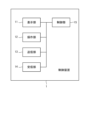
- Functional block diagram of control device Diagram showing an example of a monitoring screen displayed on the display unit Diagram showing an example of the appearance of an autonomous mobile object
- Functional block diagram of autonomous mobile object Sequence diagram for explaining the first operation example of the autonomous mobile body control system
- Sequence diagram for explaining the second operation example of the autonomous mobile body control system
- FIG. 1 is a diagram showing an example of the configuration of an autonomous mobile body control system 100 according to the present embodiment.
- the autonomous mobile body control system 100 includes a control device 1 and a plurality of autonomous mobile bodies 2.
- the plurality of autonomous mobile bodies 2 included in the autonomous mobile body control system 100 constitute one group.
- the control device 1 and each autonomous mobile body 2 belonging to the group are communicably connected via a network NW such as the Internet.
- NW such as the Internet
- the autonomous mobile body control system 100 includes four autonomous mobile bodies 2, but the present disclosure is not limited thereto.
- the number of autonomous mobile bodies 2 included in the autonomous mobile body control system 100 can be freely changed depending on the purpose.
- each of the plurality of autonomous mobile bodies 2 autonomously moves toward a preset destination.
- the control device 1 displays information (camera images, etc.) indicating the surroundings of the autonomous mobile bodies 2 to the supervisor, and the supervisor can monitor each autonomous mobile body 2 via the control device 1. Monitor whether the vehicle is moving autonomously without any problems and whether it is in a dangerous situation.
- Each of the plurality of autonomous mobile bodies 2 can stop autonomous movement as necessary and move according to remote control by the control device 1. That is, the autonomous mobile body 2 is configured to be able to transition between an autonomous movement mode and a remote control mode.
- the control device 1 is a device used by a supervisor to monitor a plurality of autonomous mobile bodies 2, and is also a device used by a supervisor to remotely control at least one of the plurality of autonomous mobile bodies 2. It is a device that
- the autonomous mobile body 2 is a transport robot that transports articles within a predetermined area, such as outdoors, indoors, a specific facility, or private land.
- the destination of the autonomous mobile body 2 is set, for example, to the destination of the article, or the place where the conveyance robot receives the article.
- the autonomous mobile object 2 may be a vacuum cleaner, a mobile object for various sensing purposes, a communication robot for communicating with people, a car, a train, a flying object, etc. that can transport not only goods but also people. There may be.
- the autonomous mobile body 2 may be a monitoring robot that monitors various meters in a factory.
- FIG. 2 is a functional block diagram of the control device 1. As shown in FIG. As shown in FIG. 2, the control device 1 includes a display section 11, an operation section 12, a transmission section 13, a reception section 14, and a control section 15.
- the receiving unit 14 is an example of a receiving unit according to the present disclosure.
- the display unit 11 is a display device such as a liquid crystal display (LCD) or an organic EL (electro luminescence) display.
- the display unit 11 may be a stationary display, or may be a mobile display such as a portable liquid crystal display or a head mount display (HMD) including virtual reality (VR) goggles.
- the display unit 11 displays, for example, camera images sent from each of the plurality of autonomous mobile bodies 2 controlled by the control device 1.
- the operation unit 12 is an operation device that accepts operations by a supervisor who monitors the plurality of autonomous mobile bodies 2 via the control device 1.
- the operation unit 12 is configured by, for example, at least one of a mouse, a keyboard, a touch pad, a trackball, a joystick, a game controller, a game pad, various keys and buttons, or a combination thereof.
- a touch pad it may be overlapped with an LCD panel or the like of the display unit 11 to form a so-called touch panel.
- FIG. 3 is a diagram showing an example of a monitoring screen displayed on the display unit 11.
- the monitoring screen S1 illustrated in FIG. 3 is a screen for monitoring four autonomous mobile bodies 2.
- the monitoring screen S1 includes surrounding images I1 to I4 and operation buttons B1 to B4 displayed on the screen.
- the surrounding images I1 to I4 are images sent from different autonomous moving bodies 2 and showing the surroundings of each autonomous moving body 2.
- the surrounding images I1 to I4 are images taken by a camera provided on the front side of the autonomous mobile body 2, for example.
- the surrounding images I1 to I4 may be moving images.
- the number of surrounding images displayed on the monitoring screen S1 may be freely settable depending on the number of autonomous mobile bodies 2 to be monitored, the number of autonomous mobile bodies 2 that the observer wants to monitor at once, and the like.
- the operation buttons B1 to B4 are buttons that accept operations for remotely controlling each autonomous mobile body 2 when it becomes necessary to remotely control each autonomous mobile body 2.
- Each of the operation buttons B1 to B4 is composed of a plurality of buttons. These multiple buttons are buttons for accepting different operations (for example, movement in each direction, stopping, etc.).
- buttons are displayed for each surrounding image, but the number of operation buttons does not have to be four.
- the number, size, position, etc. of the operation buttons may be freely settable based on the control details that the supervisor performs on the autonomous mobile body 2.
- the transmitter 13 transmits the control signal generated by the controller 15 to the autonomous mobile body 2 via the network NW.
- the receiving unit 14 receives various information including surrounding images from the autonomous mobile body 2 .
- the transmitter 13 and the receiver 14 are shown as separate structures, but they may be a single structure (for example, a transmitter/receiver).
- the control unit 15 controls the overall operation of the control device 1. Specifically, the control unit 15 performs control to display the image received from the autonomous mobile body 2 via the reception unit 14 on the display unit 11. Furthermore, the control unit 15 generates a control signal for controlling the autonomous mobile body 2 based on the operation of the operating unit 12 by the observer, and causes the autonomous mobile body 2 to transmit the generated control signal via the transmitting unit 13 . Details of the control signal will be described later.
- Each functional block of the control device 1 described above can be realized by a computer such as a personal computer (PC) including, for example, a CPU, a storage device, and an input/output device.
- PC personal computer
- the autonomous mobile body control system 100 of the present disclosure includes a plurality of autonomous mobile bodies 2 that belong to a group, and each autonomous mobile body 2 has substantially the same structure and function.
- FIG. 4 is a diagram showing an example of the appearance of the autonomous mobile body 2.
- FIG. 4 shows the autonomous mobile body 2 viewed from the side.
- the autonomous mobile body 2 includes a main body 21, wheels 22, and a sensor section 23.
- the main body 21 is the main body portion of the autonomous mobile body 2.
- the main body 21 is, for example, a housing that houses each component of the autonomous mobile body 2.
- the main body 21 may further include a storage section for storing articles, for example, when the autonomous mobile body 2 is used for purposes such as delivering articles.
- the wheels 22 are wheels that move the autonomous mobile body 2.
- the wheels 22 are rotated by a drive unit 25, which will be described later, to move the autonomous mobile body 2.
- the wheels 22 include, for example, a front wheel and a rear wheel, and the autonomous mobile body 2 may move by rotating only either the front wheel or the rear wheel. Further, at least one of the front wheels and the rear wheels may serve as a steering wheel that determines the direction of movement of the autonomous mobile body 2.
- the autonomous mobile body 2 is assumed to have four wheels 22.
- the number of wheels 22 is not limited to this, and may be one, two, three, six, etc.
- At least one of the plurality of wheels 22 may be, for example, an omniwheel (a wheel that can move in multiple directions).
- the autonomous mobile body 2 may have a crawler (infinite track) or a plurality of legs instead of the wheels 22, and may be configured to move using this.
- the sensor unit 23 is a group of sensors that acquire information regarding the situation around the autonomous mobile body 2 (hereinafter referred to as environmental information).
- the number and positions of the sensors included in the autonomous mobile body 2 may be arbitrarily settable depending on the type and accuracy of the environmental information to be acquired.
- the sensor unit 23 includes, for example, a camera (imaging device) that photographs the surroundings of the autonomous mobile body 2, a proximity sensor that detects the presence or absence of an adjacent object, and a distance sensor that detects the distance to surrounding objects and the shape of the object (for example, , LiDAR), etc.
- FIG. 5 is a functional block diagram of the autonomous mobile body 2.
- the autonomous mobile body 2 includes a control section 24, a driving section 25, a transmitting section 26, and a receiving section 27 in addition to the sensor section 23 as functional blocks.
- the control unit 24 is an example of a control unit according to the present disclosure.
- the transmitter 26 is an example of a transmitter according to the present disclosure.
- the control unit 24 controls the entire operation of the autonomous mobile body 2. Specifically, the control unit 24 can mutually shift between the autonomous driving mode and the remote control mode based on the control signal received from the control device 1. In the autonomous driving mode, the control unit 24 controls the drive unit to autonomously move the autonomous mobile body 2 to the destination based on information regarding the surrounding situation of the autonomous mobile body 2 acquired by the sensor unit 23. 25. Further, in the remote control mode, the control unit 24 controls the drive unit 25 to move or stop the autonomous mobile body 2 based on the control signal received from the control device 1. Further, the control unit 24 may generate a request signal including a request to the control device 1 based on information regarding the surrounding situation of the autonomous mobile body 2.
- control unit 24 there are multiple types of control signals that the control unit 24 transmits to the autonomous mobile body 2. Details of the control signal will be described later.
- control unit 24 controls the autonomous mobile body 2 to stop the autonomous mobile body in a safe place. conduct.
- the supervisor cannot monitor other autonomous mobile units 2 while remotely controlling autonomous mobile units 2 other than his or her own. This is because it becomes difficult to ensure the safety of autonomous mobile bodies 2 other than the autonomous mobile body 2 that has shifted to the remote control mode.
- control unit 24 Details of the control of the autonomous mobile body 2 by the control unit 24 will be described later.
- the drive unit 25 controls the operation of the wheels 22 based on the control of the control unit 24.
- the drive unit 25 is configured by, for example, at least one motor, and rotates at least one of the plurality of wheels 22 as a drive wheel.
- two rear wheels among the four wheels 22 are drive wheels.
- the drive unit 25 may change the traveling direction of the autonomous mobile body 2 by differentiating the outputs of the left and right rear wheels. By using two front wheels among the four wheels as omni wheels, the autonomous mobile body 2 can move without any problem even if the direction of travel is changed.
- the transmitting unit 26 transmits the environmental information acquired by the sensor unit 23 to the control device 1 via the network NW. Further, the transmitter 26 may transmit a request signal generated by the controller 24 to the control device 1.
- the receiving unit 27 receives various signals such as a control signal from the control device 1 via the network NW.
- the transmitter 26 and the receiver 27 are shown as separate configurations, but they may be a single configuration (for example, a transmitter/receiver).
- Control in autonomous movement mode Control of the autonomous mobile body 2 in the autonomous movement mode by the control unit 24 will be explained.
- the autonomous mobile body 2 has previously acquired map information within the area in which it can move, and has stored the map information in a storage unit (not shown) or the like.
- the map information is based on, for example, environmental information obtained by the sensor section 23 when a supervisor actually runs the autonomous mobile body 2 within the movable area by remote control before starting the service of the autonomous mobile body control system 100. It suffices if it is generated.
- the control unit 24 uses environmental information obtained from the sensor unit 23, map information stored in the storage unit, etc., and destination information indicating the destination specified by the control device 1. Based on this, the driving route is determined. The control unit 24 then controls the drive unit 25 to move the autonomous mobile body 2 along the travel route. Thereby, the autonomous mobile body 2 can autonomously move to the destination. In addition to the environmental information, map information, and destination information, the control unit 24 also uses position information regarding the position of the aircraft acquired using GNSS (Global Navigation Satellite System) such as GPS satellites. may be further used to perform autonomous movement control.
- GNSS Global Navigation Satellite System
- the control unit 24 While the autonomous mobile body 2 is autonomously moving, the control unit 24 constantly determines whether or not to continue the autonomous movement based on environmental information. For example, when the control unit 24 determines that danger has occurred around the autonomous mobile body 2, it stops the autonomous movement of the autonomous mobile body 2 and generates a request signal requesting remote control to the control device 1. Examples of cases in which the control unit 24 determines that a danger has occurred include when a person, another vehicle (including another autonomous moving object), an obstacle, etc. approaches the autonomous moving object 2, or when a pedestrian crossing, An example of this is when the driver approaches a place where the risk of driving is relatively high, such as a railroad crossing.
- Control in remote control mode Control of the autonomous mobile body 2 in the remote control mode by the control unit 24 will be explained.
- a supervisor performs an operation to control the operation of the autonomous mobile body 2 based on the environmental information of the autonomous mobile body 2 displayed on the control device 1 .
- the control device 1 Based on the operation, the control device 1 generates a first control signal for remotely controlling the autonomous mobile body 2 to be remotely controlled.
- the first control signal is one of the control signals of this embodiment.
- the first control signal includes, for example, control information that specifies the moving direction and moving speed of the autonomous mobile body 2.
- the control unit 24 controls the drive unit 25 to move or stop the autonomous mobile body 2 based on the control information.
- Control performed by the control unit 24 when another autonomous mobile body 2 shifts to the remote control mode will be described.
- the control unit 24 determines that the autonomous mobile body 2 is located within a stoppable area at that point. Determine whether or not. Note that the control unit 24 determines whether or not another autonomous mobile body 2 other than the self-machine has shifted to the remote control mode using a second control signal or a third control signal (details will be described later) received from the control device 1. Recognize based on.
- the stoppable area is an area where it is assumed in advance that the autonomous mobile body 2 can safely stop, and is an area other than the stoppable area.
- the unstoppable area is an area where danger or inconvenience (such as blocking the passage of people) is expected to occur if the autonomous mobile body 2 stops.
- Examples of areas where the vehicle can stop include sidewalks, parks, passageways within facilities, etc. It is more preferable that the stopping area is set at the end of a sidewalk, a park, or a passage within a facility so as not to obstruct the passage of people. Examples of areas where the vehicle cannot stop include crosswalks, railroad crossings, roadways, and areas near the entrances and exits of homes and shops.
- the stoppable area and the non-stoppable area may be set in advance by the administrator, provider, etc. of the autonomous mobile body control system 100, and the position of each area may be shown in the map information.
- the control unit 24 determines whether or not the own aircraft is located within the stoppable area based on the position information of the own aircraft and the position of the stoppable area or the non-stoppable area shown in the map information.
- the control unit 24 ensures the safety of the own aircraft by stopping the own aircraft on the spot. Further, if it is determined that the own aircraft is not within the stoppable area (located within the stoppable area), the control unit 24 causes the own aircraft to continue moving along the traveling route, and when the own aircraft moves to the stoppable area. And stop your machine. Thereby, even if the own vehicle is not located within the stoppable region at the time when another autonomous mobile body 2 shifts to the remote control mode, the safety of the own vehicle can be ensured.
- the autonomous mobile body control system 100 includes four autonomous mobile bodies 2A, 2B, 2C, and 2D, and these autonomous mobile bodies 2A, 2B, 2C, and 2D form one group. It is assumed that this is configured.
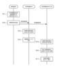
- FIG. 6 is a sequence diagram for explaining the first operation example of the autonomous mobile body control system 100.
- each of the autonomous mobile bodies 2A to 2D is moving in autonomous movement mode.
- step S1 the control device 1 receives an operation by a supervisor to remotely control the autonomous mobile body 2A.
- Such operations may be performed, for example, when a supervisor views the environmental information of each autonomous mobile body 2 and determines that remote control is necessary, or when the autonomous mobile body 2 falls into a dangerous situation. This is performed by the supervisor when the supervisor recognizes that the control device 1 has received a request signal requesting control.
- step S2 the control device 1 transmits a first control signal to the autonomous mobile body 2A that is the target of remote control, and transmits a first control signal to the autonomous mobile bodies 2B, 2C, and 2D that are not the target of remote control. , a second control signal different from the first control signal is transmitted.
- the second control signal is one of the control signals of this embodiment.
- the first control signal is a control signal for remotely controlling the autonomous mobile body 2A.
- the first control signal includes control information that specifies the direction and speed of movement of the autonomous mobile body 2A.
- the second control signal is a control signal for stopping the autonomous mobile bodies 2B, 2C, and 2D at a safe position.
- the second control signal includes information indicating to the autonomous mobile bodies 2B, 2C, and 2D that the autonomous mobile body 2A other than the autonomous mobile body has shifted to the remote control mode, and an instruction to autonomously stop the autonomous mobile body 2A. Contains information.
- step S3 the autonomous mobile body 2A that has received the first control signal shifts to remote control mode, and thereafter moves based on remote control by the supervisor. Note that, for safety, it is desirable that the autonomous mobile body 2A temporarily stop on the spot until it receives the first control signal and shifts from the autonomous movement mode to the remote control mode. After that, for example, when the supervisor performs an operation on the control device 1 to end remote control, the autonomous mobile body 2A may transition to the autonomous movement mode again.
- step S4 the autonomous mobile bodies 2B, 2C, and 2D that have received the second control signal recognize that the other autonomous mobile body 2A has shifted to the remote control mode, and each autonomous mobile body 2B, 2C, and 2D recognizes that the other autonomous mobile body 2A has shifted to the remote control mode, and each autonomous mobile body Determine whether it is located within.
- step S5 the autonomous mobile bodies 2B, 2C, and 2D stop their own vehicles based on the result of the determination in step S4. More specifically, when it is determined in step S4 that the self-machine is located within the stoppable area, the autonomous mobile bodies 2B, 2C, and 2D stop further movement and stop the self-machine. On the other hand, if it is determined in step S4 that the own aircraft is not located within the stoppable area, the autonomous mobile bodies 2B, 2C, and 2D continue moving along the movement route up to that point and enter the stoppable area. Stop your machine at this point.
- the other autonomous mobile bodies 2B, 2C, and 2D in the same group immediately stop.
- the safety of the autonomous mobile bodies 2B, 2C, and 2D is ensured while the autonomous mobile bodies 2A is being remotely controlled, that is, while the autonomous mobile bodies 2B, 2C, and 2D are not monitored by the supervisor. be able to.
- one autonomous mobile body 2A shifts to the remote control mode
- the other autonomous mobile bodies 2B, 2C, and 2D are not located within the stoppable area, they will stop after moving to the stoppable area. By stopping the vehicle on the spot, it is possible to prevent situations that could otherwise become dangerous.
- the control device 1 when shifting the autonomous mobile body 2A to the remote control mode, the control device 1 sends a first control signal to the autonomous mobile body 2A and a first control signal to the autonomous mobile bodies 2B, 2C, and 2D. 2 control signals were respectively transmitted.
- the control device 1 transmits the same third control signal to all autonomous mobile bodies 2A to 2D.
- the third control signal includes object information for specifying the autonomous mobile object (in this case, the autonomous mobile object 2A) that is the object of remote control, and control information for controlling the control object.
- the third control signal is one of the control signals of this embodiment.
- the control information included in the third control signal is equivalent to the control information included in the first control signal in the first operation example.
- other autonomous mobile objects that are not subject to remote control autonomous mobile objects 2B, 2C, and 2D in this case
- the target information is, for example, an identification number given in advance to each autonomous mobile body 2, a host name used during communication, or an IP address.
- FIG. 7 is a sequence diagram for explaining a second operation example of the autonomous mobile body control system 100.
- each of the autonomous mobile bodies 2A to 2D is moving in autonomous movement mode.
- step S11 the control device 1 receives an operation by the supervisor to remotely control the autonomous mobile body 2A.
- step S12 the control device 1 sends object information indicating that the object of remote control (hereinafter referred to as the control object) is the autonomous mobile object 2A to all the autonomous mobile objects 2A to 2D belonging to the group. transmitting a third control signal including the third control signal;
- step S13 the autonomous mobile body 2A determines whether or not it is a control target based on the target information of the third control signal.
- the autonomous mobile body 2A is a control target, so in step S14, the autonomous mobile body 2A shifts to remote control mode.
- step S15 the autonomous mobile bodies 2B, 2C, and 2D each determine whether or not they are the control target based on the target information of the third control signal.
- the autonomous mobile bodies 2B, 2C, and 2D are not control targets.
- each of the autonomous mobile bodies 2B, 2C, and 2D determines whether or not it is located within the stoppable area.
- step S17 the autonomous mobile bodies 2B, 2C, and 2D stop their own vehicles based on the result of the determination in step S16. More specifically, when it is determined in step S16 that the self-machine is located within the stoppable area, the autonomous mobile bodies 2B, 2C, and 2D stop further movement and stop the self-machine. On the other hand, if it is determined in step S16 that the own aircraft is not located within the stoppable area, the autonomous mobile bodies 2B, 2C, and 2D continue moving along the movement route up to that point and enter the stoppable area. Stop your machine at this point.
- the other autonomous mobile bodies 2B, 2C, and 2D in the same group immediately stop.
- the safety of the autonomous mobile bodies 2B, 2C, and 2D is ensured while the autonomous mobile bodies 2A is being remotely controlled, that is, while the autonomous mobile bodies 2B, 2C, and 2D are not monitored by the supervisor. be able to.
- one autonomous mobile body 2A shifts to the remote control mode
- the other autonomous mobile bodies 2B, 2C, and 2D are not located within the stoppable area, they will stop after moving to the stoppable area. By stopping the vehicle on the spot, it is possible to prevent situations that could otherwise become dangerous.
- the autonomous mobile body 2 to be controlled (autonomous mobile body 2A in FIGS. 6 and 7) is an autonomous mobile body to be remotely controlled by a supervisor.
- an autonomous mobile body to be controlled is not limited to a target to be remotely controlled, and may be a target for various other types of control.
- the autonomous mobile object to be controlled may abandon its previous destination and autonomously move toward a newly set destination under the control of a supervisor.
- control performed on an autonomous mobile object to be controlled include the following.
- the autonomous mobile object to be controlled may make vocalizations to people around the autonomous mobile object or start conversations with people under the control of a supervisor.
- people around the autonomous vehicle and the supervisor may have a remote conversation, or, for example, an AI (Artificial Intelligence) installed in the autonomous vehicle or a computer that can communicate with the autonomous vehicle may be used. etc. may carry out a conversation with a person.
- AI Artificial Intelligence
- the autonomous mobile object to be controlled may read instruments and meters installed at various locations in a factory or the like in real time under the control of a supervisor, and transmit the reading results to the control device.
- the supervisor when the supervisor views the environmental information of each autonomous mobile body 2 and determines that remote control is necessary, or when the control device 1 receives a request from the autonomous mobile body 2 for remote control.
- the supervisor recognizes that the signal has been received, the supervisor performs an operation to shift the autonomous mobile body 2 to the remote control mode.
- the following examples may be cited as to the trigger for an autonomous mobile body to shift to the remote control mode.
- the control device when a control device loses communication with an autonomous mobile object, or when a delay of more than a predetermined time occurs, the control device prompts a supervisor to shift the autonomous mobile object to remote control mode.
- An announcement may be made to encourage this. For example, if an autonomous mobile object has a problem with its own sensor, such as when the condition of its own sensor deteriorates (for example, the sensor surface becomes dirty and cannot acquire environmental information), or when an abnormality occurs in the motor of the drive unit, etc.
- the autonomous mobile object may transmit a request signal to the control device.
- multiple autonomous mobile bodies monitor each other's operating states using sensors, etc., and an autonomous mobile body that detects that another autonomous mobile body is in a state where autonomous movement is difficult for some reason may notify the control device.
- a request signal requesting that the other autonomous mobile body enter remote control mode may also be transmitted.
- the autonomous mobile body may transmit a request signal to the control device to remotely control the autonomous mobile body.
- the autonomous mobile bodies 2 other than the control target receive the second control signal
- the autonomous mobile bodies 2 Based on the position of the stoppable area, it is determined whether the own aircraft is located within the stoppable area. For example, the position of the stoppable area may not be shown in the map information, and the second control signal may include information indicating the position of the stoppable area.
- the autonomous mobile bodies 2 other than the control target are based on the result of the determination as to whether or not the own vehicle is located within the stoppable area. Based on this, the aircraft was stopped. For example, whether or not an autonomous mobile object other than the controlled object can stop itself is based on environmental information around it, instead of the result of determining whether it is located within a stoppable area. may be judged.
- the autonomous mobile body may perform an operation such as moving to a sidewalk and then stopping, instead of stopping itself on the spot.
- the present disclosure is useful for an autonomous mobile body control system that controls a plurality of autonomous mobile bodies.
- Control device 100 Autonomous mobile body control system 1 Control device 11 Display unit 12 Operation unit 13 Transmission unit 14 Receiving unit 15 Control unit 2, 2A, 2B, 2C, 2D Autonomous mobile body 21 Main body 22 Wheels 23 Sensor unit 24 Control unit 25 Drive unit 26 Transmitting section 27 Receiving section
Landscapes
- Engineering & Computer Science (AREA)
- Aviation & Aerospace Engineering (AREA)
- Radar, Positioning & Navigation (AREA)
- Remote Sensing (AREA)
- Physics & Mathematics (AREA)
- General Physics & Mathematics (AREA)
- Automation & Control Theory (AREA)
- Control Of Position, Course, Altitude, Or Attitude Of Moving Bodies (AREA)
Abstract
Description
図2は、制御装置1の機能ブロック図である。図2に示すように、制御装置1は、表示部11と、操作部12と、送信部13と、受信部14と、制御部15と、を備える。受信部14は、本開示の受信部の一例である。
次に、自律移動体2について説明する。上述したように、本開示の自律移動体制御システム100は、グループに属する複数の自律移動体2を備えるが、それぞれの自律移動体2はほぼ同じ構造および機能を有している。
制御部24による、自律移動体2の自律移動モードにおける制御について説明する。前提として、自律移動体2は、移動できるエリア内の地図情報を事前に取得しており、図示しない記憶部などに地図情報を格納している。地図情報は、例えば自律移動体制御システム100のサービス開始前に、監視者が自律移動体2の移動できるエリア内を遠隔制御により実際に走行させて、センサ部23により得られた環境情報に基づいて生成されればよい。
制御部24による、自律移動体2の遠隔制御モードにおける制御について説明する。遠隔操作モードにおいては、制御装置1に表示される自律移動体2の環境情報に基づいて、監視者が自律移動体2の動作を制御するための操作を行う。制御装置1は、当該操作に基づいて、遠隔制御対象の自律移動体2に対して、遠隔制御を実行するための第1制御信号を生成する。第1制御信号は、本実施の形態の制御信号の1つである。
制御部24による、他の自律移動体2が遠隔操作モードに移行した場合の制御について説明する。
以下では、自律移動体制御システム100の全体の動作例について説明する。
以下説明する動作例では、グループを構成する複数の自律移動体2がそれぞれ自律移動モードで自律移動している間に、グループに含まれる1つの自律移動体2が遠隔制御モードに移行する際の動作について詳細に説明する。
上述した第1の動作例では、自律移動体2Aを遠隔制御モードに移行させる場合、制御装置1は、自律移動体2Aに対し第1制御信号を、自律移動体2B、2C、2Dに対し第2制御信号を、それぞれ送信していた。第2の動作例では、第1の動作例と異なり、制御装置1は、全ての自律移動体2A~2Dに対して、同じ第3制御信号を送信する。第3制御信号は、遠隔制御の対象である自律移動体(ここでは自律移動体2A)を特定する対象情報、および制御対象を制御するための制御情報を含んでいる。第3制御信号は、本実施の形態の制御信号の1つである。第3制御信号に含まれる制御情報は、第1の動作例における第1制御信号に含まれる制御情報と同等のものである。これにより、遠隔制御の対象ではない他の自律移動体(ここでは自律移動体2B、2C、2D)は、対象情報に基づいて、自機が遠隔制御の対象ではないことを判断できるようになっている。
以上、本開示の実施の形態について説明したが、本開示は、上述した実施の形態に限定されるものではなく、本開示の趣旨を逸脱しない範囲で、適宜変形して実施することが可能である。
1 制御装置
11 表示部
12 操作部
13 送信部
14 受信部
15 制御部
2,2A,2B,2C,2D 自律移動体
21 本体
22 車輪
23 センサ部
24 制御部
25 駆動部
26 送信部
27 受信部
Claims (8)
- 複数の自律移動体と、
前記複数の自律移動体の少なくともいずれかを制御対象として制御する制御信号を前記複数の自律移動体のそれぞれに対して送信する制御装置と、を備え、
前記複数の自律移動体のうち、前記制御対象以外の自律移動体は、自機が停止可能領域内に位置するか否かを判断し、判断の結果に基づいて停止する、
自律移動体制御システム。 - 前記制御対象以外の自律移動体は、自機が前記停止可能領域内に位置すると判断した場合、さらなる移動を中断して停止し、自機が前記停止可能領域内に位置しないと判断した場合、前記停止可能領域外まで移動した後に停止する、
請求項1に記載の自律移動体制御システム。 - 前記制御装置は、操作部を介して所定の操作を受け付けた場合に、制御対象の自律移動体に対して前記制御対象の自律移動体を制御する第1制御信号を送信し、前記制御対象以外の自律移動体に対して前記判断を行わせる第2制御信号を送信する、
請求項1に記載の自律移動体制御システム。 - 前記制御装置は、操作部を介して所定の操作を受け付けた場合に、前記複数の自律移動体の全てに対して、制御対象の自律移動体を特定する対象情報および前記制御対象の自律移動体を制御する制御情報を含む第3制御信号を送信し、
前記複数の自律移動体のそれぞれは、前記第3制御信号に基づいて、自機が前記制御対象以外の自律移動体であるか否かの判定を行う、
請求項1に記載の自律移動体制御システム。 - 複数の自律移動体によって構成されるグループに属する自律移動体であって、
制御信号を受信する受信部と、
前記複数の自律移動体の少なくともいずれかを制御対象とした第1制御信号とは異なる第2制御信号を受信した場合に、自機が停止可能領域内に位置するか否かを判断し、判断に基づいて停止する制御部と、
を備える、自律移動体。 - 複数の自律移動体によって構成されるグループに属する自律移動体であって、
制御信号を受信する受信部と、
前記複数の自律移動体のうち、制御対象の自律移動体を特定する対象情報および前記制御対象の自律移動体を制御する制御情報を含む第3制御信号を受信した場合に、自機が前記制御対象以外の自律移動体であるか否かを判定し、前記制御対象以外の自律移動体であると判定したとき、自機が停止可能領域内に位置するか否かを判断し、判断の結果に基づいて停止する制御部と、
を備える、自律移動体。 - グループに属する複数の自律移動体のそれぞれに対して制御信号を送信する制御装置であって、
前記複数の自律移動体の少なくともいずれかを制御対象として制御する操作を受け付ける操作部と、
前記操作に基づいて、前記制御対象の自律移動体に対して前記制御対象の自律移動体を制御する第1制御信号を送信し、前記制御対象以外の自律移動体に対して、自機が停止可能領域内に位置するか否かを判断させ、判断の結果に基づいて停止させる第2制御信号を送信する送信部と、
を備える、制御装置。 - グループに属する複数の自律移動体のそれぞれに対して制御信号を送信する制御装置であって、
前記複数の自律移動体の少なくともいずれかを制御対象として制御する操作を受け付ける操作部と、
前記操作に基づいて、前記複数の自律移動体の少なくともいずれかが制御対象であることを示す対象情報および前記制御対象の自律移動体を制御する制御情報を含む第3制御信号を前記グループの全ての自律移動体に対して送信する送信部と、
を備える、制御装置。
Priority Applications (4)
| Application Number | Priority Date | Filing Date | Title |
|---|---|---|---|
| EP23842698.5A EP4560423A4 (en) | 2022-07-21 | 2023-06-02 | AUTONOMOUS MOBILE BODY CONTROL SYSTEM, AUTONOMOUS MOBILE BODY, AND CONTROL DEVICE |
| JP2024534958A JPWO2024018766A1 (ja) | 2022-07-21 | 2023-06-02 | |
| CN202380053999.3A CN119585690A (zh) | 2022-07-21 | 2023-06-02 | 自主移动体控制系统、自主移动体及控制装置 |
| US19/032,837 US20250165003A1 (en) | 2022-07-21 | 2025-01-21 | Autonomous movable body control system, autonomous movable body, and control device |
Applications Claiming Priority (2)
| Application Number | Priority Date | Filing Date | Title |
|---|---|---|---|
| JP2022-116520 | 2022-07-21 | ||
| JP2022116520 | 2022-07-21 |
Related Child Applications (1)
| Application Number | Title | Priority Date | Filing Date |
|---|---|---|---|
| US19/032,837 Continuation US20250165003A1 (en) | 2022-07-21 | 2025-01-21 | Autonomous movable body control system, autonomous movable body, and control device |
Publications (1)
| Publication Number | Publication Date |
|---|---|
| WO2024018766A1 true WO2024018766A1 (ja) | 2024-01-25 |
Family
ID=89617456
Family Applications (1)
| Application Number | Title | Priority Date | Filing Date |
|---|---|---|---|
| PCT/JP2023/020680 Ceased WO2024018766A1 (ja) | 2022-07-21 | 2023-06-02 | 自律移動体制御システム、自律移動体、および制御装置 |
Country Status (5)
| Country | Link |
|---|---|
| US (1) | US20250165003A1 (ja) |
| EP (1) | EP4560423A4 (ja) |
| JP (1) | JPWO2024018766A1 (ja) |
| CN (1) | CN119585690A (ja) |
| WO (1) | WO2024018766A1 (ja) |
Citations (4)
| Publication number | Priority date | Publication date | Assignee | Title |
|---|---|---|---|---|
| JPH0895635A (ja) | 1994-09-01 | 1996-04-12 | Caterpillar Inc | 自律走行車両用の遠隔制御装置と方法 |
| JP2021033447A (ja) * | 2019-08-20 | 2021-03-01 | ソニー株式会社 | 移動装置、移動体制御システム、および移動体制御方法、並びにプログラム |
| JP2021036796A (ja) * | 2019-08-30 | 2021-03-11 | 国立研究開発法人農業・食品産業技術総合研究機構 | 作業車両の遠隔制御システム、遠隔操作装置および遠隔制御方法 |
| JP2022116520A (ja) | 2021-01-29 | 2022-08-10 | Jfeスチール株式会社 | 金属板の防眩性評価方法 |
Family Cites Families (3)
| Publication number | Priority date | Publication date | Assignee | Title |
|---|---|---|---|---|
| WO2018208789A1 (en) * | 2017-05-08 | 2018-11-15 | Chase Arnold | Autonomous vehicle enhancement system |
| RU2020113342A (ru) * | 2017-09-14 | 2021-10-14 | ЮНИВЕРСАЛ СИТИ СТЬЮДИОС ЭлЭлСи | Способы автономной перевозки |
| US11892836B2 (en) * | 2020-01-27 | 2024-02-06 | Liebherr Mining Equipment Newport News Co. | System for controlling a plurality of autonomous vehicles on a mine site |
-
2023
- 2023-06-02 JP JP2024534958A patent/JPWO2024018766A1/ja active Pending
- 2023-06-02 EP EP23842698.5A patent/EP4560423A4/en active Pending
- 2023-06-02 WO PCT/JP2023/020680 patent/WO2024018766A1/ja not_active Ceased
- 2023-06-02 CN CN202380053999.3A patent/CN119585690A/zh active Pending
-
2025
- 2025-01-21 US US19/032,837 patent/US20250165003A1/en active Pending
Patent Citations (4)
| Publication number | Priority date | Publication date | Assignee | Title |
|---|---|---|---|---|
| JPH0895635A (ja) | 1994-09-01 | 1996-04-12 | Caterpillar Inc | 自律走行車両用の遠隔制御装置と方法 |
| JP2021033447A (ja) * | 2019-08-20 | 2021-03-01 | ソニー株式会社 | 移動装置、移動体制御システム、および移動体制御方法、並びにプログラム |
| JP2021036796A (ja) * | 2019-08-30 | 2021-03-11 | 国立研究開発法人農業・食品産業技術総合研究機構 | 作業車両の遠隔制御システム、遠隔操作装置および遠隔制御方法 |
| JP2022116520A (ja) | 2021-01-29 | 2022-08-10 | Jfeスチール株式会社 | 金属板の防眩性評価方法 |
Non-Patent Citations (1)
| Title |
|---|
| See also references of EP4560423A4 |
Also Published As
| Publication number | Publication date |
|---|---|
| EP4560423A4 (en) | 2025-11-05 |
| CN119585690A (zh) | 2025-03-07 |
| EP4560423A1 (en) | 2025-05-28 |
| JPWO2024018766A1 (ja) | 2024-01-25 |
| US20250165003A1 (en) | 2025-05-22 |
Similar Documents
| Publication | Publication Date | Title |
|---|---|---|
| US12468299B2 (en) | Arranging passenger pickups for autonomous vehicles | |
| US11716598B2 (en) | Early boarding of passengers in autonomous vehicles | |
| US12474702B2 (en) | System and method for autonomous operation of a machine | |
| US20230259836A1 (en) | Identifying unassigned passengers for autonomous vehicles | |
| US11747811B1 (en) | Attempting to pull over for autonomous vehicles | |
| JP6893140B2 (ja) | 制御装置、制御方法、制御プログラム及び制御システム | |
| CA3076006C (en) | Detecting and responding to propulsion and steering system errors for autonomous vehicles | |
| JP2022109895A (ja) | 自律車両用応答者監督システム | |
| US12348907B1 (en) | Augmented reality display to preserve user privacy | |
| CN110520812A (zh) | 用于远程控制车辆的方法和系统 | |
| JP7340669B2 (ja) | 制御装置、制御方法、制御プログラム及び制御システム | |
| WO2021229881A1 (ja) | 走行経路生成装置、走行経路生成方法、及び自動運転システム | |
| US20250165003A1 (en) | Autonomous movable body control system, autonomous movable body, and control device | |
| EP3679444B1 (en) | Detecting and responding to traffic redirection for autonomous vehicles | |
| KR102841300B1 (ko) | 3인칭 시야를 갖는 무인차 자율주행을 위한 드론 커플링 교통 체계 시스템 |
Legal Events
| Date | Code | Title | Description |
|---|---|---|---|
| WWE | Wipo information: entry into national phase |
Ref document number: 2024534958 Country of ref document: JP |
|
| WWE | Wipo information: entry into national phase |
Ref document number: 202380053999.3 Country of ref document: CN |
|
| WWE | Wipo information: entry into national phase |
Ref document number: 2023842698 Country of ref document: EP |
|
| NENP | Non-entry into the national phase |
Ref country code: DE |
|
| ENP | Entry into the national phase |
Ref document number: 2023842698 Country of ref document: EP Effective date: 20250221 |
|
| WWP | Wipo information: published in national office |
Ref document number: 202380053999.3 Country of ref document: CN |
|
| WWP | Wipo information: published in national office |
Ref document number: 2023842698 Country of ref document: EP |