WO2024019048A1 - 空調機及び制御方法 - Google Patents
空調機及び制御方法 Download PDFInfo
- Publication number
- WO2024019048A1 WO2024019048A1 PCT/JP2023/026259 JP2023026259W WO2024019048A1 WO 2024019048 A1 WO2024019048 A1 WO 2024019048A1 JP 2023026259 W JP2023026259 W JP 2023026259W WO 2024019048 A1 WO2024019048 A1 WO 2024019048A1
- Authority
- WO
- WIPO (PCT)
- Prior art keywords
- temperature
- fan
- indoor
- temperature sensor
- air conditioner
- Prior art date
- Legal status (The legal status is an assumption and is not a legal conclusion. Google has not performed a legal analysis and makes no representation as to the accuracy of the status listed.)
- Ceased
Links
Images




Classifications
-
- F—MECHANICAL ENGINEERING; LIGHTING; HEATING; WEAPONS; BLASTING
- F24—HEATING; RANGES; VENTILATING
- F24F—AIR-CONDITIONING; AIR-HUMIDIFICATION; VENTILATION; USE OF AIR CURRENTS FOR SCREENING
- F24F11/00—Control or safety arrangements
- F24F11/30—Control or safety arrangements for purposes related to the operation of the system, e.g. for safety or monitoring
-
- F—MECHANICAL ENGINEERING; LIGHTING; HEATING; WEAPONS; BLASTING
- F24—HEATING; RANGES; VENTILATING
- F24F—AIR-CONDITIONING; AIR-HUMIDIFICATION; VENTILATION; USE OF AIR CURRENTS FOR SCREENING
- F24F11/00—Control or safety arrangements
- F24F11/70—Control systems characterised by their outputs; Constructional details thereof
- F24F11/72—Control systems characterised by their outputs; Constructional details thereof for controlling the supply of treated air, e.g. its pressure
- F24F11/74—Control systems characterised by their outputs; Constructional details thereof for controlling the supply of treated air, e.g. its pressure for controlling air flow rate or air velocity
- F24F11/77—Control systems characterised by their outputs; Constructional details thereof for controlling the supply of treated air, e.g. its pressure for controlling air flow rate or air velocity by controlling the speed of ventilators
-
- F—MECHANICAL ENGINEERING; LIGHTING; HEATING; WEAPONS; BLASTING
- F24—HEATING; RANGES; VENTILATING
- F24F—AIR-CONDITIONING; AIR-HUMIDIFICATION; VENTILATION; USE OF AIR CURRENTS FOR SCREENING
- F24F11/00—Control or safety arrangements
- F24F11/50—Control or safety arrangements characterised by user interfaces or communication
- F24F11/61—Control or safety arrangements characterised by user interfaces or communication using timers
-
- F—MECHANICAL ENGINEERING; LIGHTING; HEATING; WEAPONS; BLASTING
- F24—HEATING; RANGES; VENTILATING
- F24F—AIR-CONDITIONING; AIR-HUMIDIFICATION; VENTILATION; USE OF AIR CURRENTS FOR SCREENING
- F24F2110/00—Control inputs relating to air properties
- F24F2110/10—Temperature
-
- F—MECHANICAL ENGINEERING; LIGHTING; HEATING; WEAPONS; BLASTING
- F24—HEATING; RANGES; VENTILATING
- F24F—AIR-CONDITIONING; AIR-HUMIDIFICATION; VENTILATION; USE OF AIR CURRENTS FOR SCREENING
- F24F2140/00—Control inputs relating to system states
- F24F2140/20—Heat-exchange fluid temperature
Definitions
- the present invention relates to an air conditioner and a control method.
- This disclosure claims priority based on Japanese Patent Application No. 2022-114905 filed in Japan on July 19, 2022, the contents of which are incorporated herein by reference.
- a multi-type air conditioner 100 that includes a plurality of indoor units 20, 21, 22, and 23 for one outdoor unit 10.
- the indoor units 20 to 23 share the refrigerant sent out by the outdoor unit 10, so if too much refrigerant accumulates in the indoor heat exchanger of the indoor unit 20, it is transferred to the indoor units 21 to 23.
- the amount of refrigerant supplied decreases, and the air conditioning capacity of the indoor units 21 to 23 decreases.
- the thermostat is turned OFF (thermo OFF is an operating state in which the indoor temperature reaches the set temperature and heat exchange between the refrigerant flowing through the indoor heat exchanger of the indoor unit 20 and the indoor air is not required).
- the gas refrigerant supplied to the indoor heat exchanger condenses and liquefies, and the refrigerant accumulates in the indoor heat exchanger of the indoor unit 20.
- the multi-type air conditioner 100 even when the thermostat is turned off, the refrigerant is supplied to the indoor heat exchanger, and the refrigerant is condensed by operating the fan or the like.
- the multi-type air conditioner 100 is configured such that when the thermostat is turned off during heating operation, , the fan of the indoor unit 20 performing heating operation is operated to prevent condensation of the refrigerant.
- Patent Document 1 discloses a fan control method for preventing overheating that occurs when the above-mentioned fan is operated intermittently. Patent Document 1 does not disclose control for restarting heating operation at an appropriate timing even if the fan is stopped when the thermostat is turned off.
- the present disclosure provides an air conditioner and a control method that can solve the above problems.
- an air conditioner is a multi-type air conditioner that includes an outdoor unit, a plurality of indoor units, and a control device, and the outdoor unit and the plurality of indoor units are connected by refrigerant piping.
- the indoor unit includes an indoor heat exchanger, a fan, and a first temperature sensor, and is connected to a second temperature sensor provided in a room to be air-conditioned, and the indoor unit is connected to a second temperature sensor provided in a room to be air-conditioned.
- the device includes means for stopping the fan when the indoor unit that is performing heating operation turns off the thermostat when the indoor temperature reaches a set temperature and heat exchange in the indoor heat exchanger is not required; means for storing the temperature measured by the second temperature sensor when the fan is turned off as a reference temperature; or a means for restarting the operation of the fan when the temperature decreases by more than 100%, and a means for restarting the operation of the fan, and when a predetermined time elapses after restarting the operation of the fan, the indoor temperature is switched from the thermo-OFF state to the temperature measured by the first temperature sensor. and means for determining whether to switch to thermo-on mode, which performs heat exchange with the exchanger.
- a control method for a multi-type air conditioner that includes an outdoor unit, a plurality of indoor units, and a control device, and in which the outdoor unit and the plurality of indoor units are connected via refrigerant piping.
- the indoor unit includes an indoor heat exchanger, a fan, and a first temperature sensor, and is connected to a second temperature sensor provided in a room to be air-conditioned. , the step of stopping the fan when the indoor unit that is performing heating operation turns off the thermostat when the indoor temperature reaches a set temperature and heat exchange in the indoor heat exchanger is not required; and the step of turning off the thermostat.
- thermo-ON mode for performing heat exchange.
- the thermostat can be turned on at an appropriate timing.
- FIG. 1 is a schematic diagram of a multi-type air conditioner according to an embodiment. It is a schematic diagram showing an example of the refrigerant circuit of the multi-type air conditioner concerning an embodiment. It is a diagram showing an example of a control device for an indoor unit according to an embodiment. It is a diagram showing an example of a room equipped with an indoor unit according to an embodiment.
- FIG. 3 is a diagram illustrating an example of settings related to fan control according to the embodiment.
- FIG. 3 is a first diagram showing an example of fan control according to the embodiment.
- FIG. 6 is a second diagram showing an example of fan control according to the embodiment.
- FIG. 7 is a third diagram showing an example of fan control according to the embodiment. It is a flowchart which shows an example of control of the fan concerning an embodiment.
- FIG. 1 is a schematic diagram showing an example of a multi-type air conditioner according to an embodiment.
- a multi-type air conditioner is an air conditioner in which multiple indoor units are connected to one outdoor unit.
- the air conditioner 100 in FIG. 1 is a multi-type air conditioning system that includes an outdoor unit 10 and a plurality of indoor units 20, 21, 22, and 23.
- the outdoor unit 10 and each of the indoor units 20 to 23 are connected by refrigerant pipes 30 through which refrigerant passes.
- the number of outdoor units 10, indoor units 20, etc. is not limited to the number shown in FIG. For example, there may be two or three indoor units 20, or five or more indoor units. There may be two or more outdoor units 10.
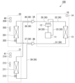
- FIG. 2 schematically shows a refrigerant circuit of a multi-type air conditioner 100 when there is one outdoor unit 10 and two indoor units 20, etc. (20, 21).
- the outdoor unit 10 includes a compressor 11, a four-way valve 12, an outdoor heat exchanger 13, and a control device 14.
- the discharge side of the compressor 11 and the four-way valve 12 are connected by a pipe 34
- the four-way valve 12 and the outdoor heat exchanger 13 are connected by a pipe 32
- the four-way valve 12 and the suction side of the compressor 11 are connected by a pipe 33.
- the four-way valve 12 and the joint 3A are connected by a pipe 35.
- the outdoor heat exchanger 13 and the joint 3B are connected by a pipe 31.
- the control device 14 controls the compressor 11 and the like.
- the indoor unit 20 includes an indoor heat exchanger 201, an expansion valve 202, a fan 203, a temperature sensor 204, and a control device 40.
- the pipe 36 connects the joint 3A and the indoor heat exchanger 201
- the pipe 37 connects the indoor heat exchanger 201 and the joint 3B
- the expansion valve 202 is provided in the pipe 37.
- the fan 203 is provided near the suction port of the indoor unit 20, sucks indoor air, and sends it to the indoor heat exchanger 201.
- the temperature sensor 204 is provided near the suction port of the indoor unit 20 and measures the indoor temperature.
- Whether to turn off the thermostat or turn on the thermostat when the indoor unit 20 is in heating operation is determined based on the temperature difference between the heating set temperature of the indoor unit 20 and the temperature measured by the temperature sensor 204. For example, when the temperature measured by the temperature sensor 204 reaches the set temperature, the control device 40 determines to turn off the heating operation, and when the temperature measured by the temperature sensor 204 falls by a predetermined value or more below the heating set temperature, the control device 40 turns off the thermostat. It is determined that it is ON. The control device 40 controls the expansion valve 202 and the fan 203 in accordance with thermo ON and thermo OFF (described later).
- the configuration of the indoor unit 21 is similar to the indoor unit 20.
- the indoor unit 21 includes an indoor heat exchanger 211, an expansion valve 212, a fan 213, a temperature sensor 214, and a control device 41.
- Piping 38 connects joint 3A and indoor heat exchanger 211
- piping 39 connects indoor heat exchanger 211 and joint 3B
- expansion valve 212 is provided in piping 39.
- the control device 41 controls the expansion valve 212 and the fan 213.
- the four-way valve 12 is set for heating operation, and the high temperature and high pressure gas refrigerant discharged by the compressor 11 is transferred to the pipe 34, the four-way valve 12, and the pipes 35, 36. It is supplied to the indoor heat exchanger 201 of the indoor unit 20 through the pipes 34, 35, and 38, and is supplied to the indoor heat exchanger 211 of the indoor unit 21 through the pipes 34, 35, and 38.
- the refrigerant supplied to the indoor heat exchanger 201 exchanges heat with the air sent out by the fan 203 and condenses, is depressurized by the expansion valve 202, and is supplied to the outdoor heat exchanger 13 through the pipes 37 and 31.
- the refrigerant supplied to the indoor heat exchanger 211 exchanges heat with the air sent out by the fan 213, condenses, is depressurized by the expansion valve 212, and passes through the pipes 39 and 31 to the outdoor heat exchanger. 13.
- the refrigerant supplied to the outdoor heat exchanger 13 is vaporized by heat exchange with the outside air, and the vaporized refrigerant is sucked into the compressor 11 through the pipe 32, the four-way valve 12, and the pipe 33.
- the indoor units 20 and 21 share the refrigerant, so for example, if too much refrigerant accumulates in the indoor heat exchanger 201 of the indoor unit 20, The amount of refrigerant supplied to the indoor unit 21 will decrease. Therefore, when the indoor unit 20 turns off the thermostat while the indoor units 20 and 21 are in heating mode, for example, the control device 40 performs control to prevent too much refrigerant from accumulating in the indoor heat exchanger 201. Specifically, the control device 40 throttles the opening degree of the expansion valve 202 to reduce the amount of refrigerant flowing into the indoor heat exchanger 201, and controls the fan 203 using another control other than the conventional fan stop or intermittent operation.
- control is performed to appropriately detect the indoor temperature while stopping the fan for a long time. Details of the fan control according to this embodiment will be described later. After the thermostat is turned off, when the indoor temperature drops and the thermostat is turned on, the control device 40 returns the opening degree of the expansion valve 202 and operates the fan 203 as usual.
- fan control Next, fan control according to this embodiment will be described with reference to FIGS. 3 to 6C. In the following, fan control when the indoor unit 20 is in the thermo-off operating state will be described as an example, but the same applies to other indoor units 21 and the like.
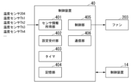
- FIG. 3 is a diagram illustrating an example of an indoor unit control device according to the embodiment.
- the control device 40 is, for example, a computer device such as a microcomputer. As illustrated, the control device 40 includes a sensor information acquisition section 401, a setting reception section 402, a timer 403, a storage section 404, a control section 405, and a communication section 406.
- the control device 40 performs various controls regarding the indoor unit 20, and in this specification, the functions controlled by the fan 203 will be explained.
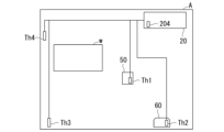
- FIG. 4 shows a room A in which the indoor unit 20 is provided.
- Room A is provided with an indoor unit 20, a remote controller 50 for the indoor unit 20, a refrigerant detector 60, and temperature sensors Th3 and Th4.
- a temperature sensor 204 is provided near the suction port of the indoor unit 20, a temperature sensor Th1 is provided on the remote control 50, and a temperature sensor Th2 is provided on the refrigerant detector 60.
- the indoor unit 20 is provided in the upper part of the room A.
- the remote control 50 is provided at a height of about 1 m from the floor.
- the refrigerant detector 60 is provided near the floor (at a position of 0.3 m or less from the floor) in order to detect refrigerant leaking from the indoor unit 20 (refrigerant is heavier than air, so it accumulates near the floor). Therefore, the temperature sensor 204 measures the temperature in the upper part of room A, near the ceiling, the temperature sensor Th1 measures the temperature in the vicinity of 1 m from the floor, and the temperature sensor Th2 measures the temperature in the lower part of room A, near the floor. do.
- the temperature sensors Th3 and Th4 are, for example, remote thermistors, and can be provided at arbitrary positions. In the example of FIG.
- the temperature sensor Th3 is provided in the upper part of the room A away from the indoor unit 20, and the temperature sensor Th4 is provided in the lower part of the room A away from the refrigerant detector 60.
- the positions of the temperature sensors Th3 and Th4 are merely examples, and they may be provided at other positions.
- the number of temperature sensors including temperature sensors Th1 and Th2 is arbitrary. For example, only the temperature sensor Th1 built into the remote control 50 may be used, or only the temperature sensor Th1 and the temperature sensor Th2 may be used.
- the temperature sensor in room A is provided at a different height from the temperature sensor 204 of the indoor unit 20, and when a plurality of sensors are provided as shown in the figure, the temperature sensor in room A is installed at a different height so that the temperature distribution in the height direction in room A can be detected.
- the plurality of sensors are provided at different heights.
- temperature sensors may be provided at separate positions even at the same height so that the temperature distribution of the entire room can be detected. While the thermostat is turned off during heating operation, it is desirable to stop the operation of the fan 203 to suppress condensation of the refrigerant. However, if the fan 203 is stopped, a problem arises in that the indoor temperature cannot be determined.
- the temperature sensors Th1 to Th4 are communicably connected to the control device 40.
- the sensor information acquisition unit 401 acquires the temperatures measured by the temperature sensors Th1 to Th4 in addition to the temperature measured by the temperature sensor 204.
- the setting reception unit 402 acquires various setting information input by the user from a remote control or the like. For example, the setting receiving unit 402 obtains settings for weighting the temperatures measured by the temperature sensors Th1 to Th4.
- FIG. 5 shows an example of setting weights for temperature sensors.
- Setting example 1 is a setting example in which the temperatures measured by temperature sensors Th1 to Th4 are equally weighted.
- Setting example 2 is a setting example in which emphasis is placed on the temperature measured by temperature sensors Th2 and Th3 provided near the floor.
- Setting example 3 is a setting example in which emphasis is placed on the temperatures measured by temperature sensors Th3 and Th4.
- Setting example 3 may be used when it is thought that the temperature measured by temperature sensors Th1 and Th2 may not reflect the temperature of room A due to the influence of equipment, etc.
- Setting example 4 is a setting example in which emphasis is placed on the temperatures measured by temperature sensors Th1 and Th4. For example, if room A is a bedroom and you want to use the bed, and you want to set the temperature at a certain height as a guide, you can set it as in setting example 4.
- Setting example 5 is a setting example in which only the temperature measured by temperature sensor Th1 is used. For example, this is a setting example where there is no refrigerant detector 60 or temperature sensors Th3 and Th4.
- setting example 6 is a setting that emphasizes the temperature at the feet when only temperature sensors Th1 and Th2 are provided
- setting example 7 is a setting that emphasizes the temperature in the area where people are (downward from the center of the room).
- Setting Example 8 is a setting that emphasizes the temperature in the center of the room. Control using setting examples 6 to 8 will be described later with reference to FIGS. 6A to 6C.
- the setting reception unit 402 acquires weighting settings as illustrated in FIG. 5 and records them in the storage unit 404.
- a timer 403 measures time.
- the storage unit 404 stores various information such as temperature measurement values acquired by the sensor information acquisition unit 401 and various setting information acquired by the setting reception unit 402.
- the storage unit 404 stores various programs that implement the functions of the control device 40.
- the control unit 405 controls the indoor unit 20 and the air conditioner 100 in cooperation with the outdoor unit 10. For example, the control unit 405 controls the opening degree of the expansion valve 202 and the rotation speed of the fan 203. Control of the fan 203 when the thermostat is turned off will be explained. When the thermostat is turned off, the control unit 405 temporarily stops the fan 203. When the fan 203 is stopped, the control unit 405 monitors the temperatures measured by the temperature sensors Th1 to Th4 and determines whether to turn on the thermostat (hereinafter sometimes referred to as operation necessity determination). Decide on timing. For example, in a situation where the temperature of room A is considered to have decreased, the control unit 405 determines that it is necessary to perform a determination as to whether or not the operation is necessary.
- the control unit 405 determines whether the temperature sensors Th1 to Th4 are required to operate, determining that the temperature sensors Th1 to Th4 may not be able to accurately measure the room temperature. Decide whether to perform the judgment.
- the control unit 405 operates the stopped fan 203 for a specified period of time. When the fan 203 is operated for a specified period of time, the air in the room A is stirred and made uniform, so that the temperature sensor 204 can accurately measure the temperature in the room A. When the accurate temperature of room A can be measured by operating the fan 203, the control unit 405 determines whether or not the fan 203 needs to be operated.
- whether or not to turn on the thermostat is determined depending on whether the temperature measured by the temperature sensor 204 has decreased by a predetermined value or more from the set temperature. If it is determined that the thermostat should be turned on as a result of the operation necessity determination, the control unit 405 executes the thermostat ON operation in cooperation with the outdoor unit 10 . For example, the compressor 11 resumes operation, and the control unit 405 controls the fan 203 and the expansion valve 202 when the thermostat is turned on. If it is determined that the thermostat is not turned on, the fan control performed when the thermostat is turned off is repeated.
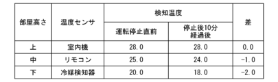
- the set temperature of room A is 27°C, and the condition for determining whether or not the operation is necessary is that the temperature decreases by 2°C.
- the temperature sensors provided in room A are temperature sensor Th1 of remote controller 50 and temperature sensor Th2 of refrigerant detector 60. It is assumed that the temperature measured by the temperature sensor 204, the temperature measured by the temperature sensor Th1 of the remote controller 50, and the temperature measured by the temperature sensor Th2 of the refrigerant detector 60 are expressed as upper, middle, and lower, respectively.
- the temperatures at the top, middle, and bottom of the fan 203 immediately before the operation is stopped are 28° C., 25° C., and 20° C., respectively.
- the temperatures at the top, middle and bottom 10 minutes after the fan 203 stops are 28°C, 24°C, and 18°C, respectively.
- the control unit 405 operates the fan 203 for a specified period of time and determines whether or not the fan 203 needs to be operated. Then, if the thermo ON condition is satisfied, the thermostat is turned ON.
- the temperatures at the top, middle and bottom 10 minutes after the fan 203 stops are 28°C, 24°C, and 17°C, respectively.
- the control unit 405 determines that it is necessary to determine whether or not operation is necessary.
- the control unit 405 operates the fan 203 for a specified period of time and determines whether or not the fan 203 needs to be operated. If the weighting that emphasizes foot temperature as in setting example 6 in FIG. 5 is set, the operation of the fan 203 and the determination of whether or not the operation is necessary will be executed before the temperature distribution shown in FIG. 6B is achieved.
- the temperatures at the top, middle and bottom 10 minutes after the fan 203 stops are 28°C, 23°C, and 16°C, respectively.
- the setting is such that the temperature in the center of the room is emphasized as in setting example 8 in FIG. After driving, the necessity of driving is determined.
- control unit 405 determines the timing to execute the operation necessity determination based on the temperature transition (decreasing degree) measured by the plurality of temperature sensors, and only when it is necessary to execute the operation necessity determination.
- the fan 203 is operated for a specified time, and the fan 203 is kept stopped for other times.
- the communication unit 406 communicates with the control device 14 of the outdoor unit 10. For example, the communication unit 406 transmits the temperature measured by the temperature sensor 204, the determination result of the necessity of operation by the control unit 405, etc. to the control device 14 of the outdoor unit 10. The communication unit 406 receives information indicating the operating states of various sensors, compressors, etc. included in the outdoor unit 10 from the control device 14 .
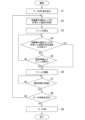
- FIG. 7 is a flowchart illustrating an example of fan control according to the embodiment. It is assumed that the weighting settings for the temperature sensors Th1 to Th4 are performed in advance, and the storage unit 404 stores a weighting setting table for the temperature sensors Th1 to Th4 illustrated in FIG. First, a predetermined thermo-off condition is satisfied (step S1). For example, when the temperature measured by the temperature sensor 204 reaches the set temperature, the thermo-off condition is satisfied. Then, the control device 40 starts control when the thermostat is turned off. For example, the control unit 405 reduces the opening degree of the expansion valve 202 and performs the fan control of this embodiment.
- the control unit 405 records the temperature measured by the temperature sensor of the other device (step S2).
- the control unit 405 records each temperature measured by the temperature sensors Th1 to Th4 acquired by the sensor information acquisition unit 401 in the storage unit 404. These temperatures are the temperatures at the start of thermo-off. For example, if the set temperature is 27 degrees Celsius, the temperature at the start of thermo-off will be 28 degrees Celsius as measured by temperature sensor 204, and 25 degrees Celsius as measured by temperature sensor Th1 of the remote control. recorded).
- the control unit 405 stops the fan 203 (step S3). Thereby, it is possible to suppress the gas refrigerant from condensing in the indoor heat exchanger 201 and the liquid refrigerant from accumulating in the indoor heat exchanger 201. Steps S2 and S3 in FIG. 7 are executed almost simultaneously. The order of steps S2 and S3 may be reversed.
- the control unit 405 determines whether the temperature measured by the temperature sensor of the other device has decreased by a predetermined temperature or more (step S4). For example, when only the temperature sensor Th1 is used as in setting example 5 in FIG. Determine whether or not the value has decreased.
- a weighted average of the temperatures measured by each sensor may be obtained, and the determination in step S4 may be made based on that temperature.
- the weighting is set as in setting example 1 in FIG. Determine whether or not. For example, when the weighting is set as in setting example 4 in FIG.
- Step S6 It is determined whether the temperature calculated by x0+temperature measured by temperature sensor Th4 x 0.5) ⁇ (1+0+0+0.5) has decreased by a predetermined temperature or more from the temperature recorded in step S2. If the calculated temperature is lower than the reference temperature recorded in step S2 by a predetermined temperature or more (step S4; Yes), the control unit 405 determines that it is necessary to perform operation necessity determination, and starts operating the fan 203. (Step S6). For example, if the above-described set temperature is 27° C. and the weighting is set according to setting example 8, if the temperature measured by the temperature sensor Th1 of the remote controller 50 becomes 23° C. after a predetermined period of time (for example, 10 minutes), the control unit 405 starts the fan 203;
- step S4 If the calculated temperature is not lower than the reference temperature by a predetermined temperature or more (step S4; No), the control unit 405 stops the fan 203 for a predetermined time or more based on the time measured by the timer 403. It is determined whether or not there is one (step S5).
- a state in which the fan 203 is stopped for more than a specified time is a situation in which the temperature measured by the temperature sensors Th1 to Th4 or the temperature calculated according to the weighting in FIG. 5 does not satisfy the condition of step S4 for more than a specified time. It is. If a predetermined period of time has passed since the thermostat was turned off, the indoor temperature should drop to some extent.
- temperature sensors Th1 to Th4 in setting example 4, the temperatures measured by temperature sensors Th1 and Th4 do not decrease, temperature sensors Th1, etc. accurately measure the temperature of room A. It may not be possible to measure it. For example, when the temperature sensor Th1 is exposed to sunlight, a temperature higher than the surrounding air temperature (actual room temperature) may be measured even after 30 minutes or more have passed since the thermostat was turned off. In such a case, the reliability of the temperature measured by the temperature sensors Th1 to Th4 is considered to be low, so the fan 203 is operated to stir and homogenize the air in the room A, and the temperature sensor 204 of the indoor unit 20 is used to Measure the temperature of A.
- step S5 If the fan 203 has been stopped for a predetermined time or more (step S5; Yes).
- the control unit 405 determines that it is necessary to perform the operation necessity determination, and operates the fan 203 (step S6). If the fan 203 has not stopped for more than the specified time (step S5; No), the process from step S4 onwards is repeated.
- the control unit 405 determines whether a predetermined prescribed time (for example, several minutes) has elapsed since the operation of the fan 203 was restarted, based on the time measured by the timer 403 (step S7).
- the specified time in step S7 is the time required until the air in the room A is equalized.
- the prescribed time in step S7 and the prescribed time in step S5 may be the same or different. If the prescribed time has not elapsed (step S7; No), the control unit 405 continues operating the fan 203 and waits until the prescribed time has elapsed.
- the control unit 405 determines whether the thermo ON condition is satisfied (determining whether operation is necessary) (step S8).
- the thermo ON condition is that the temperature measured by the temperature sensor 204 is lower than the set temperature by a predetermined temperature (for example, 1° C.) or more.
- the control unit 405 acquires, through the sensor information acquisition unit 401, the temperature measured by the temperature sensor 204 after a predetermined time has elapsed since the fan 203 restarts, and compares it with the temperature set for heating the room A.
- the control unit 405 determines that the thermo ON condition is satisfied if the temperature measured by the temperature sensor 204 is lower than the heating set temperature by a predetermined temperature or more, and otherwise determines that the thermo ON condition is not satisfied. If the thermo ON condition is not satisfied (step S8; No), the process from step S2 is repeated. That is, the control unit 405 records the temperatures measured by the temperature sensors Th1 to Th4 in the storage unit 404 at the time when it is determined that the thermo ON condition is not satisfied, and stops the fan 203 again. Then, the control unit 405 makes the determination in step S4 based on the temperature recorded this time (not when the thermostat is turned off), and makes the determination in step S5 based on the time when the fan 203 is stopped this time.
- control unit 405 repeatedly executes steps S2 to S7 until the thermo ON condition in step S8 is satisfied. Then, when the thermo ON condition is satisfied (Step S8; Yes), the control unit 405 executes thermo ON control (Step S9). For example, the control unit 405 returns the opening degree of the expansion valve 202 to the opening degree before the thermostat was turned off, and operates the fan 203. In the outdoor unit 10, the control device 14 restarts the operation of the compressor 11.
- the fan 203 when the indoor unit 20 of the multi-type air conditioner 100 turns off the thermostat during heating operation, the fan 203 is stopped. Thereby, condensation of the refrigerant and accumulation of the refrigerant in the indoor heat exchanger 201 can be prevented.
- the fan 203 even if the fan 203 is stopped while the thermostat is off, the fan 203 is only operated for a specified time when the conditions of step S4 or S5 are met, and the thermostat is turned off.
- the timing to turn on can be determined accurately. This makes it possible to improve the comfort of air conditioning compared to conventional fan stopping or intermittent operation. For example, since the fan is stopped for a long period of time, the thermostat can be turned on appropriately without causing overheating unlike conventional fan intermittent operation, so it is possible to avoid situations where the thermostat is not turned on even though the feet are cold.
- the process in FIG. 7 is a function realized by the processor included in the control device 40 reading out and executing a program from the storage unit 404.
- the air conditioner 100 of the first aspect includes an outdoor unit 10, a plurality of indoor units 20 to 23, and a control device 40, and the outdoor unit 10 and the plurality of indoor units 20 to 23 use a refrigerant. It is a multi-type air conditioner connected by piping, and the indoor unit 20 has an indoor heat exchanger 201, a fan 203, and a first temperature sensor 204, and is connected to a room A to be air-conditioned.
- the control device 40 is connected to the provided second temperature sensors Th1 to Th4, and the control device 40 controls the indoor unit 20, which is performing the heating operation, when the indoor temperature reaches the set temperature and the indoor heat exchanger 201
- the thermostat is turned off with no need for heat exchange, means for stopping the fan 203 (control unit 405, step S3) and a reference to the temperature measured by the second temperature sensors Th1 to Th4 when the thermostat is turned off.
- the temperature measured by the second temperature sensors Th1 to Th4 decreases by a predetermined temperature or more from the reference temperature after the fan is stopped, the temperature is stored by means for storing the temperature (control unit 405, step S2).
- step S4) means for restarting the operation of the fan 203 (control unit 405, step S6), and when a predetermined time has elapsed after restarting the operation of the fan 203 (control unit 405, step S7); and means (control unit 405, step S8) for determining whether to switch from the thermo-OFF state to the thermo-ON state where heat exchange is performed by the indoor heat exchanger, based on the temperature measured by the temperature sensor 204 of No. 1. Thereby, even if the fan is stopped for a long time when the thermostat is off, the thermostat can be turned on at an appropriate timing. The comfort of air conditioning can be maintained.
- the air conditioner 100 is the air conditioner 100 of (1), wherein the means for restarting the operation of the fan is such that after the fan stops, a predetermined period of time elapses while the fan is stopped. If a predetermined time has elapsed, the fan restarts operation. Thereby, the reliability of the temperature sensors Th1 to Th4 can be evaluated, and if it is considered that the reliability has decreased, it is possible to determine whether or not operation is necessary.
- the air conditioner 100 according to the third aspect is the air conditioner according to (1) to (2), in which a plurality of the second temperature sensors are provided, and a plurality of means for restarting the fan are provided.
- the fan restarts operation. Thereby, it is possible to determine whether or not to perform a driving necessity determination based on the temperature of the room calculated using a plurality of sensors provided in the room.
- the air conditioner 100 according to the fourth aspect is the air conditioner according to (1) to (3), wherein the control device sets weighting for the temperatures measured by the plurality of second temperature sensors.
- the means (setting reception unit 402) is further provided, and the means (control unit 405) for restarting the operation of the fan applies a weight based on the weighting setting to each of the temperatures measured by the plurality of first temperature sensors. Then, the reference temperature is calculated.
- the temperatures measured by temperature sensors provided at various positions in the room and to determine whether or not to perform a driving necessity determination. For example, by making settings that emphasize the temperature of the feet, it is possible to turn on the thermostat before the feet get cold while the thermostat is off.
- the air conditioner 100 according to the fifth aspect is the air conditioner of (1) to (4), in which the plurality of second temperature sensors are provided at different heights. This makes it possible to measure temperatures at various heights in the room and use the results to control switching from thermo-OFF to thermo-ON during heating operation.
- the air conditioner 100 according to the sixth aspect is the air conditioner according to (1) to (5), in which the second temperature sensor is provided at a height of 0.3 m or less from the floor. . This makes it possible to measure the temperature near the floor, which tends to get cold during heating operation.
- the air conditioner 100 according to the seventh aspect is the air conditioner of (1) to (6), in which the second temperature sensor is provided in the remote control of the indoor unit. This makes it possible to measure the temperature at a certain height in the room.
- a control method is a multi-type air conditioner that includes an outdoor unit, a plurality of indoor units, and a control device, and in which the outdoor unit and the plurality of indoor units are connected by refrigerant piping.
- the indoor unit includes an indoor heat exchanger, a fan, and a first temperature sensor, and is connected to a second temperature sensor provided in a room to be air-conditioned. , the step of stopping the fan when the indoor unit that is performing heating operation turns off the thermostat when the indoor temperature reaches a set temperature and heat exchange in the indoor heat exchanger is not required; and the step of turning off the thermostat.
- the method includes a step of determining whether to switch to a thermo-on mode that performs heat exchange.
- the thermostat can be turned on at an appropriate timing.
Landscapes
- Engineering & Computer Science (AREA)
- Chemical & Material Sciences (AREA)
- Combustion & Propulsion (AREA)
- Mechanical Engineering (AREA)
- General Engineering & Computer Science (AREA)
- Physics & Mathematics (AREA)
- Fluid Mechanics (AREA)
- Air Conditioning Control Device (AREA)
Abstract
Description
以下、本開示の一実施形態による空調機及び制御方法について図1~図7を参照して説明する。
(構成)
図1は、実施形態に係るマルチ型の空調機の一例を示す概略図である。マルチ型の空調機とは、1つの室外機に複数の室内機が接続される空調機である。図1の空調機100は、室外機10と、複数の室内機20、21、22、23とを備えるマルチ型の空調システムである。室外機10と室内機20~23の各々は、それぞれ冷媒が通過する冷媒配管30で接続されている。室外機10および室内機20等の数は図1に示す台数に限定されない。例えば、室内機20等は2~3台でも良いし、5台以上でもよい。室外機10は2台以上であってもよい。
次に、図3~図6Cを参照して、本実施形態に係るファン制御について説明する。以下では、室内機20がサーモOFFの運転状態となったときのファン制御を例に説明を行うが、他の室内機21等についても同様である。
制御装置40は、例えばマイコン等のコンピュータ装置である。図示するように制御装置40は、センサ情報取得部401と、設定受付部402と、タイマ403と、記憶部404と、制御部405と、通信部406とを備えている。制御装置40は、室内機20に関する種々の制御を行うが、本明細書では、ファン203の制御する機能を説明する。
記憶部404は、センサ情報取得部401が取得した温度の計測値、設定受付部402が取得した各種設定情報など種々の情報を記憶する。記憶部404は、制御装置40の機能を実現する各種プログラムを記憶する。
次に図7を参照して、サーモOFF時のファン制御について説明する。
図7は、実施形態に係るファンの制御の一例を示すフローチャートである。
前提として、事前に温度センサTh1~Th4に対する重み付けの設定が行われ、記憶部404は、図5に例示する温度センサTh1~Th4の重み付けの設定テーブルを記憶しているとする。最初に、所定のサーモOFF条件が成立する(ステップS1)。例えば、温度センサ204が計測した温度が設定温度に達すると、サーモOFF条件が成立する。すると、制御装置40は、サーモOFF時の制御を開始する。例えば、制御部405は、膨張弁202の開度を絞り、本実施形態のファン制御を行う。具体的には、制御部405は、他機器の温度センサが計測した温度を記録する(ステップS2)。制御部405は、センサ情報取得部401によって取得された温度センサTh1~Th4が計測した各温度を記憶部404に記録する。これらの温度はサーモOFF開始時の温度である。例えば、サーモOFF開始時の温度は、設定温度が27℃であれば、温度センサ204が計測する温度が28度、リモコンの温度センサTh1が計測する温度が25℃のようになる(25℃が記録される)。制御部405は、ファン203を停止する(ステップS3)。これにより、室内熱交換器201でガス冷媒が凝縮し、液冷媒が室内熱交換器201に溜ることを抑制することができる。図7のステップS2、S3は、ほぼ同時に実行される。ステップS2、S3の順番は、逆であってもよい。
各実施形態に記載の空調機及び制御方法は、例えば以下のように把握される。
これにより、サーモOFF時に長時間ファンを停止したとしても、適切なタイミングでサーモONすることができる。空調の快適性を維持することができる。
これにより、温度センサTh1~Th4の信頼性を評価し、信頼性が低下していると考えられる場合には、運転要否判定を行うことができる。
これにより、部屋に設けられた複数のセンサを用いて算出した部屋の温度によって、運転要否判定を行うか否かを判定することができる。
これにより、部屋の様々な位置に設けられた温度センサが計測する温度に重み付けを行って、運転要否判定を行うか否かを判定することができる。例えば、足元の温度を重視するような設定を行うことで、サーモOFF中に足元が冷える前にサーモONすることができる。
これにより、部屋の様々な高さの温度を計測し、その結果を暖房運転のサーモOFFからサーモONへの切り替え制御に利用することができる。
これにより、暖房運転中に冷えやすい床付近の温度を計測することができる。
これにより、部屋のある程度の高さ位置での温度を計測することができる。
11・・・圧縮機
12・・・四方弁
13・・・室外熱交換器
14・・・制御装置
20・・・室内機
201・・・室内熱交換器
202・・・膨張弁
203・・・ファン
204・・・温度センサ
21・・・室内機
211・・・室内熱交換器
212・・・膨張弁
213・・・ファン
214・・・温度センサ
22・・・室内機
23・・・室内機
30~39・・・配管
3A、3B・・・継手
40、41・・・制御装置
401・・・センサ情報取得部
402・・・設定受付部
403・・・タイマ
404・・・記憶部
405・・・制御部
406・・・通信部
100、100a・・・空調機
A・・・部屋
Claims (8)
- 室外機と、複数の室内機と、制御装置とを有し、前記室外機と複数の前記室内機が冷媒配管で接続されたマルチ型の空調機であって、
前記室内機は、室内熱交換器と、ファンと、第1の温度センサと、を有し、空調対象とする部屋に設けられた第2の温度センサと接続され、
前記制御装置は、
暖房運転を実行している前記室内機が、室内温度が設定温度に到達して前記室内熱交換器における熱交換が不要なサーモOFFとなると、前記ファンを停止する手段と、
前記サーモOFFとなったときに前記第2の温度センサが計測した温度を基準温度として記憶する手段と、
前記ファンの停止後に、前記第2の温度センサが計測した温度が、前記基準温度よりも所定温度以上低下すると、前記ファンの運転を再開する手段と、
前記ファンの運転を再開してから規定時間が経過すると、前記第1の温度センサが計測する温度に基づいて、前記サーモOFFから前記室内熱交換器で熱交換を行うサーモONに切り替えるかどうかを判定する手段と、
を有する空調機。 - 前記ファンの運転を再開する手段は、前記ファンの停止後に、前記ファンを停止したまま所定時間が経過したかどうかを判定し、所定時間が経過した場合には、前記ファンの運転を再開する、
請求項1に記載の空調機。 - 前記第1の温度センサが複数設けられ、
前記ファンの運転を再開する手段は、複数の前記第2の温度センサが計測した温度から算出される参照温度が、前記基準温度よりも所定温度以上低下すると、前記ファンの運転を再開する、
請求項1または請求項2に記載の空調機。 - 前記制御装置は、複数の前記第2の温度センサが計測した温度に対する重み付けを設定する手段、をさらに備え、
前記ファンの運転を再開する手段は、前記重み付けの設定に基づく重みを、複数の前記第2の温度センサが計測した温度のそれぞれに付して、前記参照温度を算出する、
請求項3に記載の空調機。 - 複数の前記第2の温度センサは、異なる高さに設けられている、
請求項3に記載の空調機。 - 前記第2の温度センサは、床から0.3m以下の高さに設けられている、
請求項1または請求項2に記載の空調機。 - 前記第2の温度センサは、前記室内機のリモコンに設けられている、
請求項1または請求項2に記載の空調機。 - 室外機と、複数の室内機と、制御装置とを有し、前記室外機と複数の前記室内機が冷媒配管で接続されたマルチ型の空調機の制御方法であって
前記室内機は、室内熱交換器と、ファンと、第1の温度センサと、を有し、空調対象とする部屋に設けられた第2の温度センサと接続され、
暖房運転を実行している前記室内機が、室内温度が設定温度に到達して前記室内熱交換器における熱交換が不要なサーモOFFとなると、前記ファンを停止するステップと、
前記サーモOFFとなったときに前記第2の温度センサが計測した温度を基準温度として記憶するステップと、
前記ファンの停止後に、前記第2の温度センサが計測した温度が、前記基準温度よりも所定温度以上低下すると、前記ファンの運転を再開するステップと、
前記ファンの運転を再開してから規定時間が経過すると、前記第1の温度センサが計測する温度に基づいて、前記サーモOFFから前記室内熱交換器で熱交換を行うサーモONに切り替えるかどうかを判定するステップと、
を有する制御方法。
Priority Applications (1)
| Application Number | Priority Date | Filing Date | Title |
|---|---|---|---|
| EP23842971.6A EP4542129A4 (en) | 2022-07-19 | 2023-07-18 | AIR CONDITIONER AND CONTROL METHOD |
Applications Claiming Priority (2)
| Application Number | Priority Date | Filing Date | Title |
|---|---|---|---|
| JP2022-114905 | 2022-07-19 | ||
| JP2022114905A JP2024013014A (ja) | 2022-07-19 | 2022-07-19 | 空調機及び制御方法 |
Publications (1)
| Publication Number | Publication Date |
|---|---|
| WO2024019048A1 true WO2024019048A1 (ja) | 2024-01-25 |
Family
ID=89617794
Family Applications (1)
| Application Number | Title | Priority Date | Filing Date |
|---|---|---|---|
| PCT/JP2023/026259 Ceased WO2024019048A1 (ja) | 2022-07-19 | 2023-07-18 | 空調機及び制御方法 |
Country Status (3)
| Country | Link |
|---|---|
| EP (1) | EP4542129A4 (ja) |
| JP (1) | JP2024013014A (ja) |
| WO (1) | WO2024019048A1 (ja) |
Cited By (1)
| Publication number | Priority date | Publication date | Assignee | Title |
|---|---|---|---|---|
| WO2026042862A1 (ja) * | 2024-08-22 | 2026-02-26 | ダイキン工業株式会社 | 空調システム、空調システムの制御方法、プログラム及び制御装置 |
Citations (6)
| Publication number | Priority date | Publication date | Assignee | Title |
|---|---|---|---|---|
| JPH0821668A (ja) * | 1994-07-05 | 1996-01-23 | Mitsubishi Electric Corp | 空気調和装置 |
| JPH11101495A (ja) * | 1997-09-29 | 1999-04-13 | Mitsubishi Heavy Ind Ltd | 多室型空気調和装置のファン制御方法及びその装置 |
| JP2003287258A (ja) * | 2002-03-28 | 2003-10-10 | Daikin Ind Ltd | 空気調和機 |
| JP2004144377A (ja) | 2002-10-23 | 2004-05-20 | Mitsubishi Heavy Ind Ltd | 複数の室内ユニットを有する空気調和装置およびその制御方法 |
| JP2011149615A (ja) * | 2010-01-21 | 2011-08-04 | Mitsubishi Electric Corp | 空気調和システム |
| JP2022114905A (ja) | 2021-01-27 | 2022-08-08 | 株式会社Kmc | 無線化ユニット及び無線化方法 |
Family Cites Families (5)
| Publication number | Priority date | Publication date | Assignee | Title |
|---|---|---|---|---|
| JP2004150679A (ja) * | 2002-10-30 | 2004-05-27 | Sanyo Electric Co Ltd | 空気調和システム |
| JP5622547B2 (ja) * | 2010-12-09 | 2014-11-12 | 日立アプライアンス株式会社 | 多室型空気調和機 |
| JP6851483B2 (ja) * | 2017-08-08 | 2021-03-31 | 三菱電機株式会社 | 空気調和機 |
| CN115151763A (zh) * | 2020-03-05 | 2022-10-04 | 三菱电机株式会社 | 空调机 |
| JP7512639B2 (ja) * | 2020-03-27 | 2024-07-09 | 株式会社富士通ゼネラル | 空気調和装置 |
-
2022
- 2022-07-19 JP JP2022114905A patent/JP2024013014A/ja active Pending
-
2023
- 2023-07-18 EP EP23842971.6A patent/EP4542129A4/en active Pending
- 2023-07-18 WO PCT/JP2023/026259 patent/WO2024019048A1/ja not_active Ceased
Patent Citations (6)
| Publication number | Priority date | Publication date | Assignee | Title |
|---|---|---|---|---|
| JPH0821668A (ja) * | 1994-07-05 | 1996-01-23 | Mitsubishi Electric Corp | 空気調和装置 |
| JPH11101495A (ja) * | 1997-09-29 | 1999-04-13 | Mitsubishi Heavy Ind Ltd | 多室型空気調和装置のファン制御方法及びその装置 |
| JP2003287258A (ja) * | 2002-03-28 | 2003-10-10 | Daikin Ind Ltd | 空気調和機 |
| JP2004144377A (ja) | 2002-10-23 | 2004-05-20 | Mitsubishi Heavy Ind Ltd | 複数の室内ユニットを有する空気調和装置およびその制御方法 |
| JP2011149615A (ja) * | 2010-01-21 | 2011-08-04 | Mitsubishi Electric Corp | 空気調和システム |
| JP2022114905A (ja) | 2021-01-27 | 2022-08-08 | 株式会社Kmc | 無線化ユニット及び無線化方法 |
Non-Patent Citations (1)
| Title |
|---|
| See also references of EP4542129A4 |
Cited By (1)
| Publication number | Priority date | Publication date | Assignee | Title |
|---|---|---|---|---|
| WO2026042862A1 (ja) * | 2024-08-22 | 2026-02-26 | ダイキン工業株式会社 | 空調システム、空調システムの制御方法、プログラム及び制御装置 |
Also Published As
| Publication number | Publication date |
|---|---|
| JP2024013014A (ja) | 2024-01-31 |
| EP4542129A1 (en) | 2025-04-23 |
| EP4542129A4 (en) | 2025-10-01 |
Similar Documents
| Publication | Publication Date | Title |
|---|---|---|
| CN105814373B (zh) | 空气调节机 | |
| CN107940826B (zh) | 多联机系统及其冷媒分配控制方法和装置 | |
| CN106958958B (zh) | 空气调节装置 | |
| JP5511761B2 (ja) | 空気調和機 | |
| JP2010133589A (ja) | 空気調和機 | |
| JP6609417B2 (ja) | 空気調和機 | |
| JP2018071886A (ja) | 空調機 | |
| JP2016008742A (ja) | 空気調和装置 | |
| WO2012164684A1 (ja) | 温度調節システム及び空気調和システム及び制御方法 | |
| JP2014190600A (ja) | 空気調和装置 | |
| JP2014153009A (ja) | 外気処理装置 | |
| JP2016003848A (ja) | 空気調和システムおよびその制御方法 | |
| JP7378660B2 (ja) | 空気調和機及び膨張弁制御方法 | |
| CN110637198A (zh) | 空调系统 | |
| WO2024019048A1 (ja) | 空調機及び制御方法 | |
| WO2018221052A1 (ja) | 制御装置、それを備えたマルチ型空気調和システム、及び制御方法並びに制御プログラム | |
| JP2017156003A (ja) | 空気調和装置 | |
| JP5900463B2 (ja) | 空気調和システム | |
| JP6755396B2 (ja) | 空気調和装置 | |
| JP2007155261A (ja) | 空気調和機 | |
| CN110637199A (zh) | 空调系统 | |
| JP2018194254A (ja) | 空調システム | |
| JP3791443B2 (ja) | 空気調和機 | |
| JP4450777B2 (ja) | 空気調和機 | |
| KR101135849B1 (ko) | 공기조화기의 난방 운전 제어장치 및 방법 |
Legal Events
| Date | Code | Title | Description |
|---|---|---|---|
| 121 | Ep: the epo has been informed by wipo that ep was designated in this application |
Ref document number: 23842971 Country of ref document: EP Kind code of ref document: A1 |
|
| WWE | Wipo information: entry into national phase |
Ref document number: 2023842971 Country of ref document: EP |
|
| ENP | Entry into the national phase |
Ref document number: 2023842971 Country of ref document: EP Effective date: 20250115 |
|
| NENP | Non-entry into the national phase |
Ref country code: DE |
|
| WWP | Wipo information: published in national office |
Ref document number: 2023842971 Country of ref document: EP |