WO2024024948A1 - 施工支援装置および施工支援方法 - Google Patents
施工支援装置および施工支援方法 Download PDFInfo
- Publication number
- WO2024024948A1 WO2024024948A1 PCT/JP2023/027785 JP2023027785W WO2024024948A1 WO 2024024948 A1 WO2024024948 A1 WO 2024024948A1 JP 2023027785 W JP2023027785 W JP 2023027785W WO 2024024948 A1 WO2024024948 A1 WO 2024024948A1
- Authority
- WO
- WIPO (PCT)
- Prior art keywords
- construction support
- underground
- support device
- objects
- underground search
- Prior art date
- Legal status (The legal status is an assumption and is not a legal conclusion. Google has not performed a legal analysis and makes no representation as to the accuracy of the status listed.)
- Ceased
Links
Images


Classifications
-
- E—FIXED CONSTRUCTIONS
- E02—HYDRAULIC ENGINEERING; FOUNDATIONS; SOIL SHIFTING
- E02F—DREDGING; SOIL-SHIFTING
- E02F9/00—Component parts of dredgers or soil-shifting machines, not restricted to one of the kinds covered by groups E02F3/00 - E02F7/00
- E02F9/24—Safety devices, e.g. for preventing overload
- E02F9/245—Safety devices, e.g. for preventing overload for preventing damage to underground objects during excavation, e.g. indicating buried pipes or the like
-
- E—FIXED CONSTRUCTIONS
- E02—HYDRAULIC ENGINEERING; FOUNDATIONS; SOIL SHIFTING
- E02F—DREDGING; SOIL-SHIFTING
- E02F9/00—Component parts of dredgers or soil-shifting machines, not restricted to one of the kinds covered by groups E02F3/00 - E02F7/00
- E02F9/26—Indicating devices
- E02F9/261—Surveying the work-site to be treated
-
- E—FIXED CONSTRUCTIONS
- E02—HYDRAULIC ENGINEERING; FOUNDATIONS; SOIL SHIFTING
- E02F—DREDGING; SOIL-SHIFTING
- E02F9/00—Component parts of dredgers or soil-shifting machines, not restricted to one of the kinds covered by groups E02F3/00 - E02F7/00
- E02F9/20—Drives; Control devices
- E02F9/2025—Particular purposes of control systems not otherwise provided for
- E02F9/205—Remotely operated machines, e.g. unmanned vehicles
Definitions
- the present invention relates to a technique for preventing erroneous damage to underground objects while excavating underground with a working machine.
- a technology has been proposed that allows the excavation work to be carried out efficiently without damaging the buried object when excavating the soil around the buried object near the ground surface using a hydraulic excavator.
- Patent Document 1 the relationship between the absolute position of the buried pipe and the absolute position of the bucket cutting edge is determined, and the excavation position and excavation depth by the bucket are determined based on this relationship.
- the operator can operate the hydraulic excavator reliably and quickly while watching the monitor display while preventing damage to buried objects.
- the permissible depth and the work equipment perform excavation work based on the permissible depth, which is the depth at which the radar can perform exploration from the ground surface with a predetermined accuracy, and the exploration position surveyed by the radar.
- the excavation location is displayed on the map. For example, in a mesh-type workplace map where one workplace is divided into multiple underground exploration areas, multiple groups (multiple rank) is assigned. In the workplace map, the groups (ranks) are shown in colors, numbers, letters, etc. so that the groups (ranks) assigned in advance to each search area Qn can be identified.
- Three-dimensional images are preferable to two-dimensional images in order to help users grasp the location and orientation of underground objects, but construction support image data tends to be overloaded due to its richness of information. be.
- the present invention aims to reduce the amount of construction support data for representing underground objects, and to generate images that allow users to easily understand the position and orientation of the underground objects, and to The purpose of the present invention is to provide a device that generates data that can be used to control the operation of construction machinery to avoid contact with objects.
- the construction support device of the present invention includes: Construction work including a plurality of objects placed in each of the plurality of underground search areas to represent a depth position from the ground surface measured by an underground search device in each of the plurality of underground search areas. Generate supporting data.
- the depth position from the ground surface measured by the underground search device is determined based on the placement mode of the object in each of the plurality of underground search areas.
- Construction support data represented by is generated.
- the amount of construction support data is reduced compared to the case where construction support data is generated without all underground search results by underground search machines being aggregated in the underground search area. .
- FIG. 2 is an explanatory diagram regarding the configuration of a remote control device.
- An explanatory diagram regarding the configuration of a working machine An explanatory diagram regarding the configuration of an underground exploration device.
- An explanatory diagram regarding a work environment image and a construction support image An explanatory diagram regarding a fixed arrangement of a plurality of underground search areas.
- FIG. 3 is an explanatory diagram regarding a fluid arrangement of a plurality of underground search areas.
- FIG. 2 is an explanatory diagram regarding a method for processing underground search areas where the degree of overlap is greater than or equal to a threshold value.
- FIG. 2 is an explanatory diagram regarding a first processing method for underground search areas where the degree of overlap is less than a threshold.
- FIG. 3 is an explanatory diagram regarding a method for determining representative coordinate values.
- the construction support system shown in FIG. 1 includes a construction support device 10 as an embodiment of the present invention, a remote control device 20 configured to be able to communicate with the construction support device 10 through a network, a work machine 40, and An underground exploration device 60 is configured.
- the construction support device may include the construction support device 10, and one or two of the remote control device 20, the work machine 40, and the underground exploration device 60.
- the mutual communication network of the construction support device 10 and the remote control device 20, the mutual communication network of the construction support device 10 and the working machine 40, and the mutual communication network of the construction support device 10 and the underground search machine 60 are the same. may also be quite different.
- the construction support device 10 is configured by one or more computers or server computers. As shown in FIG. 1, the construction support device 10 includes a database 102, an underground search result recognition element 120, a representative depth position determination element 121, and a construction support image data generation element 122. There is.
- the database 102 stores and holds, in addition to captured image data, search results for underground objects in the construction target area.
- the database 102 may be configured by a database server separate from the construction support device 10.
- Each component of the construction support device 10 is composed of an arithmetic processing unit (a single-core processor or a multi-core processor, or a processor core constituting this), reads necessary data and software from a storage device such as memory, and processes the data as a target. The arithmetic processing described below is executed according to the software.
- a component of the present invention When a component of the present invention "recognizes" information (or data), it means that the component of the present invention “recognizes” the information (or data) by receiving, reading, or searching the information, or by performing calculation processing on the underlying data or signal.
- This concept encompasses all processes that prepare information in a usable form for subsequent calculation processing, such as determining, measuring, identifying, estimating, and predicting information.
- the remote control device 20 includes a remote control device 200, a remote input interface 210, and a remote output interface 220.
- the remote control device 200 is composed of an arithmetic processing unit (single-core processor or multi-core processor, or processor cores constituting it), reads necessary data and software from a storage device such as memory, and processes the data into the software. Execute the arithmetic processing accordingly.
- the remote input interface 210 includes a remote control mechanism 211.
- the remote output interface 220 includes a remote image output device 221, a remote sound output device 222, and a remote wireless communication device 224.
- the remote control mechanism 211 includes a travel operating device, a turning operating device, a boom operating device, an arm operating device, and a bucket operating device.
- Each operating device has an operating lever that is rotated.
- the operating lever (traveling lever) of the traveling operating device is operated to move the lower traveling body 41 of the working machine 40.
- the travel lever may also serve as a travel pedal.
- a travel pedal may be provided that is fixed to the base or lower end of the travel lever.
- the operating lever (swing lever) of the swing operating device is operated to move a hydraulic swing motor that constitutes the swing mechanism 43 of the work machine 40 .
- the operating lever (boom lever) of the boom operating device is operated to move the boom cylinder 442 of the work machine 40.
- the operating lever (arm lever) of the arm operating device is operated to move the arm cylinder 444 of the work machine 40.
- the operating lever (bucket lever) of the bucket operating device is operated to move the bucket cylinder 446 of the work machine 40.
- the operation levers constituting the remote control mechanism 211 are arranged, for example, around the seat St on which the operator is seated, as shown in FIG.
- the seat St is a seating part in any form on which the operator can sit, such as a high-back chair with an armrest, a low-back chair without a headrest, or a chair without a backrest. It may be.
- Left and right travel levers 2110 corresponding to the left and right crawlers are arranged side by side in front of the seat St.
- One operating lever may also serve as multiple operating levers.
- the left operating lever 2111 provided in front of the left frame of the seat St shown in FIG. 2 functions as an arm lever when operated in the front-back direction, and when operated in the left-right direction It may also function as a pivot lever.
- the right operating lever 2112 provided in front of the right frame of the seat St shown in FIG. It may function as a bucket lever in some cases.
- the lever pattern may be arbitrarily changed according to an operator's operation instruction.
- the remote image output device 221 includes, for example, as shown in FIG. 2, a central remote image output device 2210 having substantially rectangular screens disposed in front of the seat St, diagonally to the left, and diagonally to the right. It is composed of a left side remote image output device 2211 and a right side remote image output device 2212. The shapes and sizes of the screens (image display areas) of central remote image output device 2210, left side remote image output device 2211, and right side remote image output device 2212 may be the same or different.
- the remote image output device 221 may be composed of a single curved or bendable image output device, or two or more image output devices arranged to surround the front of the sheet St.
- the left remote image is displayed so that the screen of the central remote image output device 2210 and the screen of the left remote image output device 2211 form an inclination angle ⁇ 1 (for example, 120° ⁇ 1 ⁇ 150°).
- the right edge of output device 2211 is adjacent to the left edge of central remote image output device 2210.
- the right remote image is displayed so that the screen of the central remote image output device 2210 and the screen of the right remote image output device 2212 form an inclination angle ⁇ 2 (e.g., 120° ⁇ 2 ⁇ 150°).
- the left edge of output device 2212 is adjacent to the right edge of central remote image output device 2210.
- the inclination angles ⁇ 1 and ⁇ 2 may be the same or different.
- the screens of the central remote image output device 2210, the left remote image output device 2211, and the right remote image output device 2212 may be parallel to the vertical direction, or may be inclined to the vertical direction.
- At least one image output device among the central remote image output device 2210, the left side remote image output device 2211, and the right side remote image output device 2212 may be constituted by a plurality of divided image output devices.
- the central remote image output device 2210 may be configured by vertically adjacent image output devices each having a substantially rectangular screen.
- the remote sound output device 222 is composed of one or more speakers, and includes, for example, a central sound output device 2220 arranged at the rear of the seat St, the rear of the left armrest, and the rear of the right armrest, as shown in FIG. , a left side sound output device 2221 and a right side sound output device 2222.
- the specifications of the central sound output device 2220, the left side sound output device 2221, and the right side sound output device 2222 may be the same or different.
- the work machine 40 includes a real machine control device 400, a real machine input interface 410, a real machine output interface 420, and a real machine wireless communication device 422.
- Each of the components of the actual machine control device 400 is constituted by an arithmetic processing unit (single-core processor or multi-core processor, or processor cores constituting this), reads necessary data and software from a storage device such as memory, and executes the data. Arithmetic processing according to the software is executed as a target.
- the work machine 40 is, for example, a crawler excavator (construction machine), and as shown in FIG.
- the upper revolving body 42 is provided with an upper revolving body 42.
- a cab 42C (operator's cab) is provided at the front left side of the upper revolving body 42.
- a working mechanism 44 is provided at the front central portion of the upper revolving body 42 .
- the real device input interface 410 includes a real device operating mechanism 411, a real device imaging device 412, and a real device positioning device 414.
- the actual machine operating mechanism 411 includes a plurality of operating levers arranged around a seat arranged inside the cab 42C in the same manner as the remote operating mechanism 211.
- the cab 42C is provided with a drive mechanism or a robot that receives a signal corresponding to the operating mode of the remote control lever and moves the actual control lever based on the received signal.
- the actual imaging device 412 is installed, for example, inside the cab 42C, and images the environment including at least a portion of the working mechanism 44 through the front window and left and right side windows. Some or all of the front window and side windows may be omitted.
- the actual machine positioning device 414 is configured with GPS or GNSS and, if necessary, a gyro sensor, etc., and measures the position (latitude and longitude) of the work machine 40.
- the working mechanism 44 includes a boom 441 mounted on the upper rotating body 42 so as to be able to raise and lower, an arm 443 that is rotatably connected to the tip of the boom 441, and an arm 443 that is rotatably connected to the tip of the boom 441.
- a bucket 445 is rotatably connected to the tip of the bucket 445.
- the working mechanism 44 is equipped with a boom cylinder 442, an arm cylinder 444, and a bucket cylinder 446, each of which is an extendable hydraulic cylinder.
- the boom cylinder 442 is interposed between the boom 441 and the upper revolving body 42 so as to expand and contract when supplied with hydraulic oil and rotate the boom 441 in the up-and-down direction.
- the arm cylinder 444 is interposed between the arm 443 and the boom 441 so as to expand and contract when supplied with hydraulic oil and rotate the arm 443 around a horizontal axis with respect to the boom 441 .
- the bucket cylinder 446 is interposed between the bucket 445 and the arm 443 so as to expand and contract when supplied with hydraulic oil and rotate the bucket 445 about a horizontal axis relative to the arm 443 .
- the underground search device 60 includes a search control device 600, a search storage device 602, a depth position measurement element 611, a search position measurement element 612, and a search wireless communication device 624. , is equipped with.
- the depth position measurement element 611 is constituted by an underground radar device, and measures the depth position of the underground object from the ground surface. For example, as shown in FIG. 4, a plurality of depth position measuring elements 611 may be mounted at different positions of one underground exploration device 60.
- the search position measurement element 612 is constituted by GPS or GNSS and, if necessary, a gyro sensor, etc., and measures the two-dimensional position (latitude and longitude) of the underground search device 60.
- the search storage device 602 stores and holds the depth position measured by the depth position measurement element 611 and the horizontal position measured by the search position measurement element 612 as underground search results.
- the search storage device 602 may also store and hold coordinate values of the underground radar device in a search coordinate system (a coordinate system whose position and orientation are fixed with respect to the underground search device 60).
- the search wireless communication device 624 is configured to transmit the underground search results stored in the search storage device 602 to the construction support device 10 (or database server) via the network.
- the underground search results are accumulated or saved in the database 102.
- the remote control device 200 transmits a ground situation confirmation request to the construction support device 10 through the remote wireless communication device 224 (FIG. 5/STEP 210).
- the presence or absence of the first designated operation via the remote input interface 210 may be determined by the operator, and if the determination result is positive, a ground situation confirmation request may be transmitted.
- the "first designation operation" is, for example, an operation such as a tap on the remote input interface 210 for designating the work machine 40 that the operator intends to remotely control.
- the construction support device 10 When the construction support device 10 receives the ground situation confirmation request, the construction support device 10 transmits the ground situation confirmation request to the corresponding work machine 40 (FIG. 5/C10).
- the actual machine control device 400 transmits the captured image (which has been subjected to appropriate image processing) acquired through the actual machine imaging device 412. Captured image data representing the construction support device 10 is transmitted to the construction support device 10 (FIG. 5/STEP 410).
- the construction support device 10 When the construction support device 10 receives the captured image data (FIG. 5/C11), the construction support device 10 transmits environmental image data corresponding to the captured image to the remote control device 20 (FIG. 5/STEP 110). ).
- the environmental image data is not only the captured image data itself, but also image data representing a simulated environmental image generated based on the captured image.
- the remote control device 20 When the remote control device 20 receives environmental image data through the remote wireless communication device 224 (FIG. 5/C21), the remote control device 200 outputs an environmental image according to the environmental image data to the remote image output device 221. (FIG. 5/STEP 212).
- the remote control device 200 transmits an underground situation confirmation request to the construction support device 10 via the remote wireless communication device 224 (FIG. 5/STEP 220).
- the presence or absence of the second designation operation via the remote input interface 210 may be determined by the operator, and if the determination result is positive, an underground situation confirmation request may be transmitted.
- the "second specifying operation" is, for example, an operation such as a tap on the remote input interface 210 for specifying the work machine 40 that the operator intends to remotely control.
- the second specifying operation may be the same operation as the first specifying operation, or may be a different operation.
- the underground situation confirmation request signal see FIG. 5/STEP 210) and the underground situation confirmation request (see FIG. 5/STEP 220) may be sent simultaneously by the remote control device 200 through the remote wireless communication device 224. .
- the underground search result recognition element 120 detects the underground search machine 60 in the construction target area related to the underground situation confirmation request. The results of the underground search are recognized (searched from the database 102) (FIG. 5/STEP 120).
- the construction target area is specified, for example, by a set of horizontal coordinate values (X (longitude), Y (latitude)) of the world coordinate system that represent its boundaries.
- the construction target area is determined based on communication between the construction support device 10 and the remote control device 20 or the work machine 40 to be operated by the construction support device 10, for example, based on an identifier for identifying the remote control device 20 and/or the work machine 40.
- the information is recognized by searching the database 102.
- each of the plurality of underground search areas in the construction target area the depth position (Z (depth)) from the ground surface of underground objects such as piping measured by the underground search device 60 is recognized as the underground search result.
- Each local search area is specified, for example, by a set of horizontal coordinate values (X (longitude), Y (latitude)) of the world coordinate system that represent its boundaries.
- X longitude
- Y latitude
- the plurality of underground search areas may be defined adjacent to each other or consecutively, it is preferable that the plurality of underground search areas are defined apart from each other.
- the shapes or shapes and sizes of the plurality of underground search areas may be the same or different.
- a plurality of underground search areas may be fixedly defined.
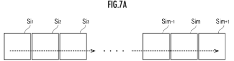
- a plurality of approximately rectangular or square underground search areas S i1 that are spaced apart from each other and are regularly arranged (in a square or triangular lattice pattern); S i2 , . . . , S im , and S im+1 may be defined as a plurality of underground search areas.
- a plurality of underground search areas S i1 , S i2 , . . . , S im , S im+1 may be regularly arranged adjacent to each other or consecutively. In this case, as shown by the dashed arrow in FIG.
- the underground search areas S i1 , S i2 , . . . , S im , S im+ are registered in the database 102 and can be recognized by the underground search result recognition element 120.
- the shape of the underground search area can be various shapes such as triangle, trapezoid, parallelogram, regular polygon (regular hexagon, regular octagon, regular dodecagon, etc.), circular shape, or elliptical shape. good.
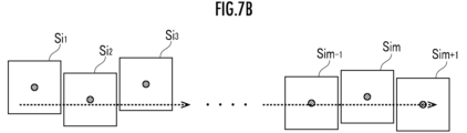
- a plurality of underground search areas may be fluidly defined according to search results by the underground search device 60.
- the movement is represented by a black circle ( ⁇ ) in FIG. 7B at each predetermined period.
- the location is an underground search point where the depth position of an underground object from the ground surface is measured.
- the underground search point (defined by two-dimensional coordinate values (X (latitude), Y (longitude))) is the center or center of gravity, and is approximately a rectangle that is irregularly arranged at a distance from each other.
- each underground search area S ik may be defined as a plurality of underground search areas.
- the size and shape of each search area S ik may be changed in various ways, it is preferable that they be defined in advance.
- the size of each underground search area S ik may be determined according to the displacement speed and predetermined period (time interval) of the underground search device 60.
- a plurality of underground search areas may be fluidly defined according to the displacement mode of the underground search device 60.
- the position of the center of gravity (defined by two-dimensional coordinate values) of the underground exploration device 60 at each predetermined period is set as the center or the center of gravity
- the A plurality of substantially rectangular or square underground search areas S i1 , S i2 , . . . , S im , S im+1 which are spaced apart may be defined as a plurality of underground search areas.
- the attitude (for example, the direction of the long side or the short side) of each underground search area S ik may be defined along the displacement direction of the underground search machine 60.
- the single underground search area S2 that remains as a result is defined as a single underground search area S- shown on the right side of FIG. 8A.
- the underground exploration area may be deleted.
- the other underground search areas are deleted except for the one underground search area where the number of depth position measurements by the underground search device 60 is the largest (or the smallest). It's okay. If all other underground search areas except for the one with the highest number of depth position measurements are deleted, construction support data with information on the depth where buried objects are likely to be located will be generated. This can contribute to improving work efficiency.
- the two areas A single underground search area S + is defined in which the medium search areas S 1 and S 2 are combined. If the degree of overlap between the two approximately rectangular underground search areas S 1 and S 2 shown on the left side of FIG. 8C is less than the threshold, the two underground search areas S 1 and S 2 shown on the right side of FIG. Two underground search areas S 1 ′ and S 2 ′ may be defined, which are displaced such that areas S 1 and S 2 are spaced apart from each other.
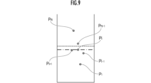
- the representative depth position determination element 121 determines each representative position of a depth position group consisting of one or more depth positions in each of the plurality of underground search areas (FIG. 5/STEP 121).
- the depth position of the underground search point P + closest to the ground surface or the underground search point P 1 furthest from the ground surface may be determined as the representative depth position of the underground search point group.
- the most frequent depth position may be determined as the representative depth position of the underground search point group.
- the construction support image data generation element 122 generates construction support image data as "construction support data" and transmits it to the remote control device 20 (FIG. 5/STEP 122).
- the construction support image data is a three-dimensional image that represents a three-dimensional image that includes a plurality of objects placed in each of a plurality of underground search areas to represent each representative depth position of a group of underground search points. This is image data.
- the construction support image data may be, for example, two-dimensional image data representing a two-dimensional image including a plurality of objects in a cross-sectional view parallel to a vertical plane, such as a topographical cross-sectional view.
- the object has a shape and size such that a substantially rectangular or square underground search area is projected in the vertical direction or depth direction, and There are closed surfaces m 1 and m 2 parallel to .
- the shapes (for example, substantially rectangular or substantially square) and sizes of the plurality of underground search areas are the same, the shapes and sizes of the plurality of closed curved surfaces as objects are also the same.
- the shapes of the plurality of underground search areas are the same, the shapes of the plurality of closed curved surfaces as objects are also the same and similar.
- the closed surface may be defined as a curved surface defined by a plurality of control points, such as a Bezier surface and/or a NURBS (non-uniform rational B-spline) surface.
- the curved surface may be defined as a curved surface having continuity (G1 continuity, G2 continuity, or G3 continuity).
- G1 continuity, G2 continuity, or G3 continuity For example, when a closed surface is defined by a Bezier triangular surface, the domain of the control net of the Bezier triangular surface is defined by a triangular mesh stretched on the horizontal plane, the underground search points are taken as control points, and the triangular patch A closed surface is defined so that the continuity of is ensured.
- the remote control device 200 When the remote control device 20 receives construction support image data through the remote wireless communication device 224 (FIG. 5/C22), the remote control device 200 outputs a construction support image corresponding to the construction support information to the remote image output device 221. It is output (FIG. 5/STEP 222).
- a plurality of closed curved surfaces m are arranged at representative depth positions of the underground search point group. 1 and m 2 are output to the remote image output device 221 in a form superimposed on the environmental image.
- the curved surfaces m 1 and m 2 are distinguishably differentiated according to their depth positions.
- the vertical line segments extending from each closed curved surface m 1 and m 2 to the ground surface may constitute a part of the object, but the vertical line segments may be omitted.
- the arrangement mode of the object is coordinate-transformed into the environment image coordinate system.
- the coordinate values of the working machine 40 in the world coordinate system are measured using GPS or the like, and the actual machine coordinate system of the actual machine imaging device 412 (a coordinate system whose position and orientation are fixed with respect to the upper revolving body 42) is measured using GPS or the like. ) may be stored and held in the storage device and/or database 102 constituting the remote control device 200.
- the operator can operate the control lever forming the remote control mechanism 211 to move the bucket 445 while viewing the environmental image output to the remote image output device 221 and the construction support image superimposed thereon.
- the real space position (latitude, longitude, and altitude) of each point on the earth's surface is measured by a ranging device (such as LiDAR or stereo camera) that constitutes the real machine input interface 410. Then, based on the result of converting the measurement result to the environmental image coordinate system, the layout of the underground search area in the captured image coordinate system and the representative depth position from the ground surface of the underground search point group in the underground search area are determined. The space occupancy of the object representing the object is determined.
- a ranging device such as LiDAR or stereo camera
- the construction support image may be output alone to the remote image output device 221 without being superimposed on the environmental image.
- a three-dimensional model image representing the space occupation mode of each of objects arranged to represent the depth position from the ground surface of the working machine 40 existing on the ground surface and the underground underground facility in the three-dimensional virtual space provides construction support.
- the image is output as an image to the remote image output device 221 separately from the environmental image. Since the arrangement of the closed curved surface represented by the construction support information is defined in the world coordinate system, the coordinate values of the work machine 40 in the world coordinate system are measured using GPS or the like, and the storage device configuring the remote control device 200 and/or may be stored and held in the database 102.
- the operation mode of the remote control mechanism 211 is recognized by the remote control device 200, and a remote control command corresponding to the operation mode is transmitted to the construction support device 10 through the remote wireless communication device 224. ( Figure 5/STEP 214).
- the remote operation command is transmitted to the work machine 40 (FIG. 5/C14).
- the actual machine control device 400 receives an operation command through the real machine wireless communication device 422 (FIG. 5/C44), the operation of the work mechanism 44, etc. is controlled (FIG. 5/STEP 414).
- the bucket 445 excavates and scoops soil in the construction target area in front of the working machine 40, the upper rotating body 42 is rotated, and the soil is dropped from the bucket 445 outside the construction target area.
- the closed surfaces m 1 and m 2 as objects only need to be arranged separately and independently so as to represent the corresponding representative depth positions, and the relative positions and postures between the plural objects can be adjusted.
- the calculation processing load required for the generation process of construction support image data can be reduced to the extent that it is not necessary.
- the construction support device 10 is configured by a computer separate from the remote control device 20, the work machine 40, and the underground exploration machine 60, but in another embodiment, the construction support device 10 It may be mounted on the device 20, the work machine 40, or the underground exploration machine 60.
- the working machine 40 was remotely controlled by the operator through the remote control device 20, but in another embodiment, the working machine 40 may be actually operated by an operator riding on the working machine 40.
- construction support image data is transmitted from the construction support device 10 to the work machine 40 (see FIG. 5/STEP 122), and a construction support image corresponding to the data is sent to the actual machine image output device that constitutes the actual machine output interface 420. It may also be output (see FIG. 5).
- the construction support image generated by the construction support device 10 may be output to a communication terminal with a display device, such as a smartphone or a tablet, held by a worker or a construction manager.
- a display device such as a smartphone or a tablet
- the communication terminal is equipped with an imaging device and has a configuration that allows acquisition of position information of the terminal by GNSS etc. and acquisition of azimuth information and angle information to which the terminal is directed by an azimuth sensor, inclination sensor, etc., the above-mentioned implementation is possible. Similar to the form, by superimposing a construction support image on an image of the surrounding area, it is possible to grasp the space occupation mode of an underground object in a three-dimensional real space.
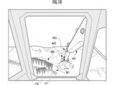
- Construction support image data representing a three-dimensional image that includes, as an object placed in the underground search area, a three-dimensional object extending from the ground surface of the underground search area to a representative depth position of the underground search point group. may be generated. For example, as shown in FIG. 10, a plurality of inverted cones m 1 and m 2 whose bases are placed on the ground surface and whose vertices are placed at representative depth positions in each of the underground search areas are objects. Construction support image data representing the included three-dimensional images may be generated. Similar to the example shown in FIG . For example, the colors (colors) are distinguishably differentiated depending on the depth positions of the closed surfaces m 1 and m 2 .
- the surface of the three-dimensional object may be defined as a curved surface defined by a plurality of control points, such as a Bezier surface and/or a NURBS (non-uniform rational B-spline) surface.
- the curved surface may be defined as a curved surface having continuity (G1 continuity, G2 continuity, or G3 continuity).
- the three-dimensional object may be a three-dimensional object of various shapes, such as an inverted pyramid such as an inverted quadrangular pyramid different from an inverted cone, an inverted frustum, a column, a sphere, or an ellipsoid.
- construction support image data that is three-dimensional image data or two-dimensional image data is generated as construction support data, but as another embodiment, underground search point groups in each of a plurality of underground search areas are generated.
- Control data may be generated as construction support data that includes a plurality of objects placed in each of the plurality of underground search areas so as to represent representative depth positions of each of the plurality of underground search areas.
- construction support data is transmitted from the construction support device 10 to the work machine 40 and/or the remote control device 20, and the actual machine control device 40 controls the plurality of construction support data included in the construction support data in a certain underground search area.
- the operation of the work machine 40 and, by extension, the work mechanism 44 may be restricted or controlled so that the depth position of the bucket 445 is stopped above the representative depth position according to the arrangement of the object.
- the working machine to which control is applied in which the operation is restricted by the control data generated from the construction support data may be operated by an operator on board the machine or operated by an operator by remote control. It can also be applied to working machines that operate automatically.
- the depth position of each of the plurality of underground search points in each of the underground search areas was measured by the underground search device 60, but in other embodiments, the depth position of each of the plurality of underground search points was measured in each of the underground search areas.
- the depth position of one underground search point is measured by the underground search device 60, and construction support data or construction support that includes an object placed in the underground search area to represent the depth position. Image data may also be generated.
- the depth position is defined as one or more underground search points P 1 , P i-1 , P i , P i+1 , P n-1 , P n of the measured underground object. It is preferable to generate the construction support data so as to represent each representative depth position of the intermediate search point group.
- the underground search device 60 searches the ground surface in at least some of the underground search areas S i1 , S i2 , . . . , S im , S im+1.
- the depths of each of the underground search points for underground objects whose depth positions have been measured are aggregated into a representative depth position.
- “Multiple underground search areas S i1 , S i2 , . . . , S im , S im+1 ” are, for example, multiple mesh-shaped underground search areas spaced apart from each other. It may be a search area, or it may be an underground search area occupied by the underground search device 60 at predetermined time intervals or every predetermined distance.
- construction support data is generated that includes objects representing representative depth positions placed in each of the plurality of underground search areas S i1 , S i2 , . . . , S im , S im+1 .
- each object only needs to be placed separately and independently so as to represent the corresponding representative depth position, and the construction support data does not require adjustment of the relative positions and postures between multiple objects.
- the calculation processing load required for the generation process is reduced.
- construction support image data representing an image including the plurality of objects is generated as the construction support data.
- construction support device having this configuration, objects representing representative depth positions arranged in each of the plurality of underground search areas S i1 , S i2 , . . . , S im , S im+1 are included.
- Construction support image data representing an image (three-dimensional image or two-dimensional image) is generated as construction support data.
- the construction support image data is Efforts are being made to reduce the amount of data.
- the output interface for example, the remote output interface 220 or the remote image output device 221 constituting this
- each of the plurality of underground search areas S i1 , S i2 , . . . , S im , S im+1 a plurality of closed curved surfaces arranged at the representative depth position are included as the plurality of objects.
- the construction support image data representing an image is generated.
- a "closed curved surface” is a concept that includes a plane and a curved surface surrounded by closed curves. In particular, when the closed surface is a flat surface, the amount of construction support image data can be further reduced.
- a plurality of underground search areas in a virtual space included in an image (three-dimensional image or two-dimensional image) output to an output interface (for example, the remote output interface 220 or the remote image output device 221 constituting the remote output interface 220)
- an output interface for example, the remote output interface 220 or the remote image output device 221 constituting the remote output interface 220
- a user who comes into contact with the output interface can grasp the space occupation state of the underground object in real space, including the depth position from the ground surface.
- a single surface corresponding to the synthesis result of the plurality of closed surfaces in each of the plurality of overlapping underground search areas S i1 , S i2 , . . . , S im , S im+1 It is preferable to generate the construction support image data representing an image in which a closed curved surface is included as a part of the plurality of objects.
- a plurality of closed surfaces corresponding to each of the plurality of overlapping underground search areas S i1 , S i2 , . . . , S im , S im+1 are aggregated into a single closed surface.
- the amount of construction support image data can be reduced by the same amount.
- the output interface e.g., remote output interface 220 or a remote image comprising the remote output interface 220 or device 221).
- a plurality of horizontal closed curved surfaces at different depth positions from the ground surface in each of the plurality of underground exploration areas are inclined with respect to the horizontal according to the difference in the depth positions. is output to the output interface as a single plane covering the .
- construction support image data representing an image including the plurality of closed curved surfaces having the same shape.
- each of the plurality of closed curved surfaces is made common (limited to the same or similar closed curved surfaces), thereby simplifying the expression of the plurality of closed curved surfaces, The amount of construction support image data can be reduced accordingly.
- the plurality of objects are classified into a plurality of object groups according to the relative arrangement of each of the plurality of objects, and each of the plurality of objects m 1 and m 2 is classified according to the one object group to which it belongs. It is preferable to generate the construction support image data representing an image that can be identified by a design.
- the data amount of the construction support image data is reduced by the amount that the designs of the plurality of objects m 1 and m 2 constituting a common object group among the plurality of object groups are made common. Efforts are being made to reduce this.
- Design means color, shape (including size), pattern, or any combination thereof, and is a concept that includes not only static design but also dynamic design.
- a plurality of common rules for extending from the ground surface to a representative depth position are set in each of the plurality of underground search areas S i1 , S i2 , . . . , S im , S im+ 1.
- the amount of construction support image data can be reduced by the amount that the three-dimensional object has, compared to the case where objects m 1 and m 2 for which such a common rule does not exist are included.
- construction support image data representing an image including the plurality of three-dimensional objects that have the same shape or have the same shape as a result of projection onto a horizontal plane.
- the shape of each of the plurality of three-dimensional objects or the shape of the projection result of each three-dimensional object onto the horizontal plane (or the ground surface) can be made common (the shape of the three-dimensional object or its projection onto the horizontal plane) can be standardized.
- the closed curved surfaces that are the projection results are the same or similar), thereby simplifying the representation of the shapes and postures of the plurality of three-dimensional objects, and reducing the amount of construction support image data accordingly.
- the plurality of underground search areas S i1 , S i2 , . . . , S im , S im+1 are spaced apart from each other.
- a plurality of objects m are placed in each of a plurality of underground search areas S i1 , S i2 , . . . , S im , S im+1 that are adjacent to each other via a boundary line. Since data representing at least part of the boundary line among objects m 1 and m 2 are common, misidentification can be avoided when the plurality of objects m 1 and m 2 are processed. .
- Construction support device 102 Database 120... Underground search result recognition element 121... Representative depth position determination element 122... Construction support image data generation element 20... Remote control device 200; Remote control device 210... Remote input interface 211... Remote Operating mechanism 220;Remote output interface 221...Remote image output device 222...Remote sound output device 224...Remote wireless communication device 40...Work machine 41...Lower traveling body 42...Upper rotating body 42C...Cab (driver's cab) 44... Working mechanism 445... Bucket 400... Actual machine control device 410... Actual machine input interface 420... Actual machine output interface 60... Underground search machine 600... Search control device 602... Search storage device 611... Depth position measurement element 612...
- Search position measurement Element 624 ...Searching wireless communication devices m1 , m2 ...Object (closed surface, three-dimensional object) P 1 ,..P i-1 ,P i ,P i+1 ,..P n-1 ,P n ..Underground search point S i1 ,S i2 ,..,S im ,S im+1 ..Underground search area .
Landscapes
- Engineering & Computer Science (AREA)
- Mining & Mineral Resources (AREA)
- Civil Engineering (AREA)
- General Engineering & Computer Science (AREA)
- Structural Engineering (AREA)
- Life Sciences & Earth Sciences (AREA)
- General Life Sciences & Earth Sciences (AREA)
- Paleontology (AREA)
- Component Parts Of Construction Machinery (AREA)
- Processing Or Creating Images (AREA)
- Operation Control Of Excavators (AREA)
Abstract
Description
複数の地中探索エリアのそれぞれにおいて地中探索機により測定された地表からの深さ位置を表わすように前記複数の地中探索エリアのそれぞれに配置されている複数のオブジェクトが含まれている施工支援データを生成する。
図1に示されている施工支援システムは、本発明の一実施形態としての施工支援装置10と、施工支援装置10と相互にネットワーク通信可能に構成されている遠隔操作装置20、作業機械40および地中探索機60と、により構成されている。施工支援装置が、施工支援装置10と、遠隔操作装置20、作業機械40および地中探索機60のうち1つまたは2つと、により構成されていてもよい。施工支援装置10および遠隔操作装置20の相互通信ネットワークと、施工支援装置10および作業機械40の相互通信ネットワークと、施工支援装置10および地中探索機60の相互通信ネットワークと、は同一であってもよく相違していてもよい。
施工支援装置10は、一または複数のコンピュータまたはサーバコンピュータにより構成されている。図1に示されているように、施工支援装置10は、データベース102と、地中探索結果認識要素120と、代表深さ位置決定要素121と、施工支援画像データ生成要素122と、を備えている。データベース102は、撮像画像データのほか、施工対象領域の地中埋設物の探索結果等を記憶保持する。データベース102は、施工支援装置10とは別個のデータベースサーバにより構成されていてもよい。施工支援装置10の各構成要素は、演算処理装置(シングルコアプロセッサまたはマルチコアプロセッサもしくはこれを構成するプロセッサコア)により構成され、メモリなどの記憶装置から必要なデータおよびソフトウェアを読み取り、当該データを対象として当該ソフトウェアにしたがった後述の演算処理を実行する。
図1に示されているように、遠隔操作装置20は、遠隔制御装置200と、遠隔入力インターフェース210と、遠隔出力インターフェース220と、を備えている。遠隔制御装置200は、演算処理装置(シングルコアプロセッサまたはマルチコアプロセッサもしくはこれを構成するプロセッサコア)により構成され、メモリなどの記憶装置から必要なデータおよびソフトウェアを読み取り、当該データを対象として当該ソフトウェアにしたがった演算処理を実行する。
遠隔操作機構211には、走行用操作装置と、旋回用操作装置と、ブーム用操作装置と、アーム用操作装置と、バケット用操作装置と、が含まれている。各操作装置は、回動操作を受ける操作レバーを有している。走行用操作装置の操作レバー(走行レバー)は、作業機械40の下部走行体41を動かすために操作される。走行レバーは、走行ペダルを兼ねていてもよい。例えば、走行レバーの基部または下端部に固定されている走行ペダルが設けられていてもよい。旋回用操作装置の操作レバー(旋回レバー)は、作業機械40の旋回機構43を構成する油圧式の旋回モータを動かすために操作される。ブーム用操作装置の操作レバー(ブームレバー)は、作業機械40のブームシリンダ442を動かすために操作される。アーム用操作装置の操作レバー(アームレバー)は作業機械40のアームシリンダ444を動かすために操作される。バケット用操作装置の操作レバー(バケットレバー)は作業機械40のバケットシリンダ446を動かすために操作される。
図1に示されているように、作業機械40は、実機制御装置400と、実機入力インターフェース410と、実機出力インターフェース420と、実機無線通信機器422と、を備えている。実機制御装置400の構成要素のそれぞれは、演算処理装置(シングルコアプロセッサまたはマルチコアプロセッサもしくはこれを構成するプロセッサコア)により構成され、メモリなどの記憶装置から必要なデータおよびソフトウェアを読み取り、当該データを対象として当該ソフトウェアにしたがった演算処理を実行する。
作業機械40は、例えばクローラショベル(建設機械)であり、図3に示されているように、クローラ式の下部走行体41と、下部走行体41に旋回機構43を介して旋回可能に搭載されている上部旋回体42と、を備えている。上部旋回体42の前方左側部にはキャブ42C(運転室)が設けられている。上部旋回体42の前方中央部には作業機構44が設けられている。
図3に示されているように、作業機構44は、上部旋回体42に起伏可能に装着されているブーム441と、ブーム441の先端に回動可能に連結されているアーム443と、アーム443の先端に回動可能に連結されているバケット445と、を備えている。作業機構44には、伸縮可能な油圧シリンダにより構成されているブームシリンダ442、アームシリンダ444およびバケットシリンダ446が装着されている。
図1に示されているように、地中探索機60は、探索制御装置600と、探索記憶装置602と、深さ位置測定要素611と、探索位置測定要素612と、探索無線通信機器624と、を備えている。
(機能)
前記構成の施工支援装置および撮像機能制御システムの機能について図5に示されているフローチャートを用いて説明する。当該フローチャートにおいて「C●」というブロックは、記載の簡略のために用いられ、データの送信および/または受信を意味し、当該データの送信および/または受信を条件として分岐方向の処理が実行される条件分岐を意味している。
前記機能を発揮する施工支援装置10によれば、複数の地中探索エリアSi1、Si2、‥、Sim、Sim+1(図7Aおよび図7B参照)のうち少なくとも一部の地中探索エリアにおいて、地中探索機60により地表からの深さ位置が測定された地中埋設物の地中探索点P1,‥Pi-1,Pi,Pi+1,‥Pn-1,Pnのそれぞれの深さが代表深さ位置に集約される(図5/STEP121、図9参照)。そして、当該複数の地中探索エリアSi1、Si2、‥、Sim、Sim+1のそれぞれに配置されている代表深さ位置を表わすオブジェクトとしての閉曲面m1、m2が含まれている3次元画像を表わす施工支援画像データが生成される(図5/STEP122、図5参照)。
遠隔出力インターフェース220を構成する遠隔画像出力装置221に出力された施工支援画像(図5参照)における複数のオブジェクトとしての閉曲面m1、m2の空間占有態様を通じて、当該遠隔画像出力装置221に接したユーザまたはオペレータに3次元実空間における地中埋設物の空間占有態様を把握させることができる。
前記実施形態では、施工支援装置10が遠隔操作装置20、作業機械40および地中探索機60とは別個のコンピュータにより構成されていたが、他の実施形態として、施工支援装置10が、遠隔操作装置20、作業機械40または地中探索機60に搭載されていてもよい。
前記深さ位置は、測定された地中埋設物の一または複数の地中探索点P1,‥Pi-1,Pi,Pi+1,‥Pn-1,Pnからなる地中探索点群のそれぞれの代表深さ位置を表わすように施工支援データを生成する
ことが好ましい。
前記複数のオブジェクトが含まれている画像を表わす施工支援画像データを前記施工支援データとして生成する
ことが好ましい。
前記複数の地中探索エリアSi1、Si2、‥、Sim、Sim+1のそれぞれにおいて、前記代表深さ位置に配置されている複数の閉曲面が前記複数のオブジェクトとして含まれている画像を表わす前記施工支援画像データを生成する
ことが好ましい。
前記複数の地中探索エリアのうち、重複する複数の地中探索エリアSi1、Si2、‥、Sim、Sim+1のそれぞれにおける複数の前記閉曲面の合成結果に相当する単一の閉曲面が前記複数のオブジェクトの一部として含まれている画像を表わす前記施工支援画像データを生成する
ことが好ましい。
形状が同一である前記複数の閉曲面が含まれている画像を表わす前記施工支援画像データを生成する
ことが好ましい。
前記複数のオブジェクトのそれぞれの相対的な配置態様に応じて当該複数のオブジェクトを複数のオブジェクト群に分類し、前記複数のオブジェクトm1、m2のそれぞれを所属先である一のオブジェクト群に応じた意匠により識別可能な画像を表わす前記施工支援画像データを生成する
ことが好ましい。
前記複数の地中探索エリアSi1、Si2、‥、Sim、Sim+1のそれぞれにおいて地表から前記代表深さ位置まで延在している複数の立体物が前記複数のオブジェクトm1、m2として含まれている画像を表わす前記施工支援画像データを生成する
ことが好ましい。
形状が同一である、または、水平面に対する投影結果の形状が同一である前記複数の立体物が含まれている画像を表わす前記施工支援画像データを生成する
ことが好ましい。
前記複数の地中探索エリアSi1、Si2、‥、Sim、Sim+1が相互に離間している
ことが好ましい。
102‥データベース
120‥地中探索結果認識要素
121‥代表深さ位置決定要素
122‥施工支援画像データ生成要素
20‥遠隔操作装置
200‥遠隔制御装置
210‥遠隔入力インターフェース
211‥遠隔操作機構
220‥遠隔出力インターフェース
221‥遠隔画像出力装置
222‥遠隔音響出力装置
224‥遠隔無線通信機器
40‥作業機械
41‥下部走行体
42‥上部旋回体
42C‥キャブ(運転室)
44‥作業機構
445‥バケット
400‥実機制御装置
410‥実機入力インターフェース
420‥実機出力インターフェース
60‥地中探索機
600‥探索制御装置
602‥探索記憶装置
611‥深さ位置測定要素
612‥探索位置測定要素
624‥探索無線通信機器
m1、m2‥オブジェクト(閉曲面、立体物)
P1,‥Pi-1,Pi,Pi+1,‥Pn-1,Pn‥地中探索点
Si1、Si2、‥、Sim、Sim+1‥地中探索エリア。
Claims (11)
- 複数の地中探索エリアのそれぞれにおいて地中探索機により測定された地表からの深さ位置を表わすように前記複数の地中探索エリアのそれぞれに配置されている複数のオブジェクトが含まれている施工支援データを生成する
施工支援装置。 - 請求項1に記載の施工支援装置において、
前記深さ位置は、測定された地中埋設物の一または複数の地中探索点からなる地中探索点群のそれぞれの代表深さ位置を表わすように施工支援データを生成する
施工支援装置 - 請求項2に記載の施工支援装置において、
前記複数のオブジェクトが含まれている画像を表わす施工支援画像データを前記施工支援データとして生成する
施工支援装置。 - 請求項3に記載の施工支援装置において、
前記複数の地中探索エリアのそれぞれにおいて、前記代表深さ位置に配置されている複数の閉曲面が前記複数のオブジェクトとして含まれている画像を表わす前記施工支援画像データを生成する
施工支援装置。 - 請求項4に記載の施工支援装置において、
前記複数の地中探索エリアのうち、重複する複数の地中探索エリアのそれぞれにおける複数の前記閉曲面の合成結果に相当する単一の閉曲面が前記複数のオブジェクトの一部として含まれている画像を表わす前記施工支援画像データを生成する
施工支援装置。 - 請求項4に記載の施工支援装置において、
形状が同一である前記複数の閉曲面が含まれている画像を表わす前記施工支援画像データを生成する
施工支援装置。 - 請求項3に記載の施工支援装置において、
前記複数のオブジェクトのそれぞれの相対的な配置態様に応じて当該複数のオブジェクトを複数のオブジェクト群に分類し、前記複数のオブジェクトのそれぞれを所属先である一のオブジェクト群に応じた意匠により識別可能な画像を表わす前記施工支援画像データを生成する
施工支援装置。 - 請求項3に記載の施工支援装置において、
前記複数の地中探索エリアのそれぞれにおいて地表から前記代表深さ位置まで延在している複数の立体物が前記複数のオブジェクトとして含まれている画像を表わす前記施工支援画像データを生成する
施工支援装置。 - 請求項8に記載の施工支援装置において、
形状が同一である、または、水平面に対する投影結果の形状が同一である前記複数の立体物が含まれている画像を表わす前記施工支援画像データを生成する
施工支援装置。 - 請求項1に記載の施工支援装置において、
前記複数の地中探索エリアが相互に離間している
施工支援装置。 - 複数の地中探索エリアのそれぞれにおいて地中探索機により地表からの深さ位置が測定された地中埋設物の一または複数の地中探索点からなる地中探索点群のそれぞれの代表深さ位置を決定する工程と、
前記代表深さ位置を表わすように前記複数の地中探索エリアのそれぞれに配置されている複数のオブジェクトが含まれている施工支援データを生成する工程と、
を含んでいる施工支援方法。
Priority Applications (3)
| Application Number | Priority Date | Filing Date | Title |
|---|---|---|---|
| US18/867,853 US20260035886A1 (en) | 2022-07-29 | 2023-07-28 | Construction assistance device and construction assistance method |
| EP23846678.3A EP4512964A4 (en) | 2022-07-29 | 2023-07-28 | CONSTRUCTION AID DEVICE AND CONSTRUCTION AID METHOD |
| CN202380054898.8A CN119585486A (zh) | 2022-07-29 | 2023-07-28 | 施工支援装置及施工支援方法 |
Applications Claiming Priority (2)
| Application Number | Priority Date | Filing Date | Title |
|---|---|---|---|
| JP2022121870A JP7597087B2 (ja) | 2022-07-29 | 2022-07-29 | 施工支援装置および施工支援方法 |
| JP2022-121870 | 2022-07-29 |
Publications (1)
| Publication Number | Publication Date |
|---|---|
| WO2024024948A1 true WO2024024948A1 (ja) | 2024-02-01 |
Family
ID=89706674
Family Applications (1)
| Application Number | Title | Priority Date | Filing Date |
|---|---|---|---|
| PCT/JP2023/027785 Ceased WO2024024948A1 (ja) | 2022-07-29 | 2023-07-28 | 施工支援装置および施工支援方法 |
Country Status (5)
| Country | Link |
|---|---|
| US (1) | US20260035886A1 (ja) |
| EP (1) | EP4512964A4 (ja) |
| JP (3) | JP7597087B2 (ja) |
| CN (1) | CN119585486A (ja) |
| WO (1) | WO2024024948A1 (ja) |
Families Citing this family (1)
| Publication number | Priority date | Publication date | Assignee | Title |
|---|---|---|---|---|
| JP7655428B1 (ja) | 2024-03-22 | 2025-04-02 | コベルコ建機株式会社 | 掘削支援装置、掘削システム、掘削支援方法、建設機械、及びプログラム |
Citations (5)
| Publication number | Priority date | Publication date | Assignee | Title |
|---|---|---|---|---|
| JP2003056010A (ja) | 2001-08-09 | 2003-02-26 | Komatsu Ltd | 地下埋設物掘削システム |
| JP2004109084A (ja) * | 2002-09-20 | 2004-04-08 | Ntt Infranet Co Ltd | ケーブル位置情報管理システム及びケーブル位置情報管理方法並びにケーブル位置情報管理プログラム |
| JP2005134015A (ja) * | 2003-10-29 | 2005-05-26 | Hitachi Constr Mach Co Ltd | 移動式作業機械の作業管理装置 |
| JP2016057235A (ja) * | 2014-09-11 | 2016-04-21 | 大阪瓦斯株式会社 | 探査装置 |
| JP2021189127A (ja) | 2020-06-04 | 2021-12-13 | 株式会社クボタ | 作業機の掘削支援システム、及び作業機の掘削支援方法 |
Family Cites Families (9)
| Publication number | Priority date | Publication date | Assignee | Title |
|---|---|---|---|---|
| JP2003075546A (ja) * | 2001-09-06 | 2003-03-12 | Toyo Machine Kogyo Kk | 地中埋設管の探知システム |
| JP5682060B2 (ja) * | 2010-12-20 | 2015-03-11 | 国際航業株式会社 | 画像合成装置、画像合成プログラム、及び画像合成システム |
| WO2014110502A1 (en) * | 2013-01-11 | 2014-07-17 | The Regents Of The University Of Michigan | Monitoring proximity of objects at construction jobsites via three-dimensional virtuality in real-time |
| JP6033209B2 (ja) * | 2013-12-11 | 2016-11-30 | 三菱電機株式会社 | 携帯用端末装置 |
| EP3730700B1 (en) * | 2017-12-21 | 2024-05-22 | Sumitomo (S.H.I.) Construction Machinery Co., Ltd. | Shovel and shovel management system |
| US10748427B1 (en) * | 2019-05-24 | 2020-08-18 | Saudi Arabian Oil Company | Systems and methods for preventing damage to unseen utility assets |
| JP7322616B2 (ja) * | 2019-09-12 | 2023-08-08 | 東京電力ホールディングス株式会社 | 情報処理装置、情報処理方法、プログラム及び掘削システム |
| IL275318A (en) * | 2020-06-11 | 2022-01-01 | G A A A Global Infrastructures Tech Ltd | A system for locating an underground infrastructure line |
| JP7779479B2 (ja) * | 2022-03-04 | 2025-12-03 | 戸田建設株式会社 | 推定結果表示システム |
-
2022
- 2022-07-29 JP JP2022121870A patent/JP7597087B2/ja active Active
-
2023
- 2023-07-28 WO PCT/JP2023/027785 patent/WO2024024948A1/ja not_active Ceased
- 2023-07-28 EP EP23846678.3A patent/EP4512964A4/en active Pending
- 2023-07-28 US US18/867,853 patent/US20260035886A1/en active Pending
- 2023-07-28 CN CN202380054898.8A patent/CN119585486A/zh active Pending
-
2024
- 2024-01-17 JP JP2024005668A patent/JP7691007B2/ja active Active
-
2025
- 2025-05-30 JP JP2025090531A patent/JP2025120205A/ja active Pending
Patent Citations (5)
| Publication number | Priority date | Publication date | Assignee | Title |
|---|---|---|---|---|
| JP2003056010A (ja) | 2001-08-09 | 2003-02-26 | Komatsu Ltd | 地下埋設物掘削システム |
| JP2004109084A (ja) * | 2002-09-20 | 2004-04-08 | Ntt Infranet Co Ltd | ケーブル位置情報管理システム及びケーブル位置情報管理方法並びにケーブル位置情報管理プログラム |
| JP2005134015A (ja) * | 2003-10-29 | 2005-05-26 | Hitachi Constr Mach Co Ltd | 移動式作業機械の作業管理装置 |
| JP2016057235A (ja) * | 2014-09-11 | 2016-04-21 | 大阪瓦斯株式会社 | 探査装置 |
| JP2021189127A (ja) | 2020-06-04 | 2021-12-13 | 株式会社クボタ | 作業機の掘削支援システム、及び作業機の掘削支援方法 |
Non-Patent Citations (1)
| Title |
|---|
| See also references of EP4512964A4 |
Also Published As
| Publication number | Publication date |
|---|---|
| EP4512964A4 (en) | 2025-10-22 |
| JP2024032802A (ja) | 2024-03-12 |
| EP4512964A1 (en) | 2025-02-26 |
| CN119585486A (zh) | 2025-03-07 |
| JP2025120205A (ja) | 2025-08-15 |
| JP7691007B2 (ja) | 2025-06-11 |
| US20260035886A1 (en) | 2026-02-05 |
| JP2024018497A (ja) | 2024-02-08 |
| JP7597087B2 (ja) | 2024-12-10 |
Similar Documents
| Publication | Publication Date | Title |
|---|---|---|
| AU2022209235B2 (en) | Display control device and display control method | |
| AU2019292457B2 (en) | Display control device, display control system, and display control method | |
| JP6867132B2 (ja) | 作業機械の検出処理装置及び作業機械の検出処理方法 | |
| JP2020117982A (ja) | 作業機械 | |
| WO2019012992A1 (ja) | 表示制御装置、表示制御方法、プログラムおよび表示システム | |
| KR20220039801A (ko) | 작업 기계 | |
| JP2005283221A (ja) | 測量データ処理システム、電子地図を格納する記憶媒体及び電子地図表示装置 | |
| WO2021060195A1 (ja) | 作業機械 | |
| JP7552494B2 (ja) | 施工支援システムおよび施工支援方法 | |
| JP2021001436A (ja) | 作業機械 | |
| JP2024012527A (ja) | 情報表示装置、方法及びプログラム | |
| WO2023100533A1 (ja) | 画像表示システム、遠隔操作支援システムおよび画像表示方法 | |
| CN108779985B (zh) | 施工管理系统 | |
| JP7691007B2 (ja) | 施工支援装置および施工支援方法 | |
| JP2020060907A (ja) | 避雷保護範囲生成システムおよびプログラム | |
| JP7107792B2 (ja) | 建設機械 | |
| US20230128501A1 (en) | Remote operation assistance device and remote operation assistance method | |
| CN114731388B (zh) | 作业支援服务器、作业支援方法以及作业支援系统 | |
| JP2024057362A (ja) | 作業支援システム、遠隔操作支援システム、作業支援方法および表示装置 | |
| JP6616149B2 (ja) | 施工方法、作業機械の制御システム及び作業機械 | |
| JP2024057361A (ja) | 作業支援装置および作業支援方法 | |
| JP2022129500A (ja) | 地形情報管理システムおよび作業機械 | |
| WO2025052859A1 (ja) | 作業支援システムおよび作業支援方法 | |
| JP2019152098A (ja) | ショベル | |
| JP2021013111A (ja) | カメラ配置評価装置、カメラ配置評価方法、及びコンピュータプログラム |
Legal Events
| Date | Code | Title | Description |
|---|---|---|---|
| 121 | Ep: the epo has been informed by wipo that ep was designated in this application |
Ref document number: 23846678 Country of ref document: EP Kind code of ref document: A1 |
|
| WWE | Wipo information: entry into national phase |
Ref document number: 2023846678 Country of ref document: EP |
|
| WWE | Wipo information: entry into national phase |
Ref document number: 18867853 Country of ref document: US |
|
| ENP | Entry into the national phase |
Ref document number: 2023846678 Country of ref document: EP Effective date: 20241120 |
|
| WWE | Wipo information: entry into national phase |
Ref document number: 202380054898.8 Country of ref document: CN |
|
| NENP | Non-entry into the national phase |
Ref country code: DE |
|
| WWP | Wipo information: published in national office |
Ref document number: 202380054898.8 Country of ref document: CN |
|
| WWP | Wipo information: published in national office |
Ref document number: 18867853 Country of ref document: US |