WO2024034038A1 - 生体情報検出装置及び生体情報検出方法 - Google Patents
生体情報検出装置及び生体情報検出方法 Download PDFInfo
- Publication number
- WO2024034038A1 WO2024034038A1 PCT/JP2022/030509 JP2022030509W WO2024034038A1 WO 2024034038 A1 WO2024034038 A1 WO 2024034038A1 JP 2022030509 W JP2022030509 W JP 2022030509W WO 2024034038 A1 WO2024034038 A1 WO 2024034038A1
- Authority
- WO
- WIPO (PCT)
- Prior art keywords
- substance
- information detection
- pulsed laser
- laser beam
- biological information
- Prior art date
- Legal status (The legal status is an assumption and is not a legal conclusion. Google has not performed a legal analysis and makes no representation as to the accuracy of the status listed.)
- Ceased
Links
Images









Classifications
-
- G—PHYSICS
- G01—MEASURING; TESTING
- G01N—INVESTIGATING OR ANALYSING MATERIALS BY DETERMINING THEIR CHEMICAL OR PHYSICAL PROPERTIES
- G01N21/00—Investigating or analysing materials by the use of optical means, i.e. using sub-millimetre waves, infrared, visible or ultraviolet light
- G01N21/17—Systems in which incident light is modified in accordance with the properties of the material investigated
- G01N21/25—Colour; Spectral properties, i.e. comparison of effect of material on the light at two or more different wavelengths or wavelength bands
- G01N21/31—Investigating relative effect of material at wavelengths characteristic of specific elements or molecules, e.g. atomic absorption spectrometry
- G01N21/35—Investigating relative effect of material at wavelengths characteristic of specific elements or molecules, e.g. atomic absorption spectrometry using infrared light
- G01N21/3577—Investigating relative effect of material at wavelengths characteristic of specific elements or molecules, e.g. atomic absorption spectrometry using infrared light for analysing liquids, e.g. polluted water
-
- A—HUMAN NECESSITIES
- A61—MEDICAL OR VETERINARY SCIENCE; HYGIENE
- A61B—DIAGNOSIS; SURGERY; IDENTIFICATION
- A61B5/00—Measuring for diagnostic purposes; Identification of persons
- A61B5/0059—Measuring for diagnostic purposes; Identification of persons using light, e.g. diagnosis by transillumination, diascopy, fluorescence
- A61B5/0062—Arrangements for scanning
-
- A—HUMAN NECESSITIES
- A61—MEDICAL OR VETERINARY SCIENCE; HYGIENE
- A61B—DIAGNOSIS; SURGERY; IDENTIFICATION
- A61B5/00—Measuring for diagnostic purposes; Identification of persons
- A61B5/0059—Measuring for diagnostic purposes; Identification of persons using light, e.g. diagnosis by transillumination, diascopy, fluorescence
- A61B5/0075—Measuring for diagnostic purposes; Identification of persons using light, e.g. diagnosis by transillumination, diascopy, fluorescence by spectroscopy, i.e. measuring spectra, e.g. Raman spectroscopy, infrared absorption spectroscopy
-
- A—HUMAN NECESSITIES
- A61—MEDICAL OR VETERINARY SCIENCE; HYGIENE
- A61B—DIAGNOSIS; SURGERY; IDENTIFICATION
- A61B5/00—Measuring for diagnostic purposes; Identification of persons
- A61B5/145—Measuring characteristics of blood in vivo, e.g. gas concentration or pH-value ; Measuring characteristics of body fluids or tissues, e.g. interstitial fluid or cerebral tissue
- A61B5/14546—Measuring characteristics of blood in vivo, e.g. gas concentration or pH-value ; Measuring characteristics of body fluids or tissues, e.g. interstitial fluid or cerebral tissue for measuring analytes not otherwise provided for, e.g. ions, cytochromes
-
- A—HUMAN NECESSITIES
- A61—MEDICAL OR VETERINARY SCIENCE; HYGIENE
- A61B—DIAGNOSIS; SURGERY; IDENTIFICATION
- A61B5/00—Measuring for diagnostic purposes; Identification of persons
- A61B5/145—Measuring characteristics of blood in vivo, e.g. gas concentration or pH-value ; Measuring characteristics of body fluids or tissues, e.g. interstitial fluid or cerebral tissue
- A61B5/1455—Measuring characteristics of blood in vivo, e.g. gas concentration or pH-value ; Measuring characteristics of body fluids or tissues, e.g. interstitial fluid or cerebral tissue using optical sensors, e.g. spectral photometrical oximeters
-
- G—PHYSICS
- G01—MEASURING; TESTING
- G01N—INVESTIGATING OR ANALYSING MATERIALS BY DETERMINING THEIR CHEMICAL OR PHYSICAL PROPERTIES
- G01N21/00—Investigating or analysing materials by the use of optical means, i.e. using sub-millimetre waves, infrared, visible or ultraviolet light
- G01N21/84—Systems specially adapted for particular applications
- G01N21/85—Investigating moving fluids or granular solids
-
- G—PHYSICS
- G01—MEASURING; TESTING
- G01N—INVESTIGATING OR ANALYSING MATERIALS BY DETERMINING THEIR CHEMICAL OR PHYSICAL PROPERTIES
- G01N33/00—Investigating or analysing materials by specific methods not covered by groups G01N1/00 - G01N31/00
- G01N33/48—Biological material, e.g. blood, urine; Haemocytometers
- G01N33/483—Physical analysis of biological material
- G01N33/487—Physical analysis of biological material of liquid biological material
-
- G—PHYSICS
- G01—MEASURING; TESTING
- G01N—INVESTIGATING OR ANALYSING MATERIALS BY DETERMINING THEIR CHEMICAL OR PHYSICAL PROPERTIES
- G01N21/00—Investigating or analysing materials by the use of optical means, i.e. using sub-millimetre waves, infrared, visible or ultraviolet light
- G01N21/17—Systems in which incident light is modified in accordance with the properties of the material investigated
- G01N21/25—Colour; Spectral properties, i.e. comparison of effect of material on the light at two or more different wavelengths or wavelength bands
- G01N21/31—Investigating relative effect of material at wavelengths characteristic of specific elements or molecules, e.g. atomic absorption spectrometry
- G01N21/35—Investigating relative effect of material at wavelengths characteristic of specific elements or molecules, e.g. atomic absorption spectrometry using infrared light
- G01N21/359—Investigating relative effect of material at wavelengths characteristic of specific elements or molecules, e.g. atomic absorption spectrometry using infrared light using near infrared light
-
- G—PHYSICS
- G01—MEASURING; TESTING
- G01N—INVESTIGATING OR ANALYSING MATERIALS BY DETERMINING THEIR CHEMICAL OR PHYSICAL PROPERTIES
- G01N2201/00—Features of devices classified in G01N21/00
- G01N2201/06—Illumination; Optics
- G01N2201/061—Sources
- G01N2201/06113—Coherent sources; lasers
-
- G—PHYSICS
- G01—MEASURING; TESTING
- G01N—INVESTIGATING OR ANALYSING MATERIALS BY DETERMINING THEIR CHEMICAL OR PHYSICAL PROPERTIES
- G01N2201/00—Features of devices classified in G01N21/00
- G01N2201/06—Illumination; Optics
- G01N2201/069—Supply of sources
- G01N2201/0696—Pulsed
- G01N2201/0697—Pulsed lasers
Definitions
- the present invention relates to a biological information detection device and a biological information detection method, and particularly to a biological information detection device and a biological information detection method that obtain the amount of a substance to be measured that is present inside a liquid biological object.
- Lactic acid contained in human blood is produced in large amounts when sugar in the blood is metabolized in anoxic conditions, such as during intense exercise.
- the concentration of lactic acid in the blood is used as a value indicating the degree of blood circulation, for example, as an indicator of a state of shock or circulatory failure.
- lactic acid concentration in blood can be treated by monitoring the lactic acid concentration in the blood.
- Measurement of lactic acid concentration in blood is generally performed by analyzing blood collected from a patient, but simple and continuous measurement is difficult, and risk management for infectious diseases associated with blood collection is difficult. Required.
- Patent Document 1 discloses a method for estimating the concentration level of a blood analyte in a patient, in which a first set of input variables includes invasively measured variables.
- the at least one first variable of the first set of input variables is influenced by the concentration level of the analyte in the patient's blood
- the at least one second variable of the first set of input variables is influenced by the concentration level of the patient's blood analyte
- receiving a first set of input variables that is unaffected by the concentration level of the analyte preprocessing at least one of the first set of input variables to generate a second set of variables; and applying a linear separation method to the variables.
- Patent Document 2 discloses a method for real-time monitoring of blood component levels in a subject, and provides a system-on-chip equipped with a wavelength tunable hybrid III-V/IV laser sensor; instructing the system-on-chip to monitor the subject's blood component levels by transmitting a signal; directing said signal to the subject's blood at a fiber optic interface; and after said signal interacts with the blood; , collecting a reflected signal from blood with a fiber optic interface; and directing the reflected signal to a reflected light photodiode.
- the reflected signal is an optical signal; converting the reflected signal from an optical signal to an electrical signal; and processing the electrical signal with a microcontroller to convert the electrical signal into a calibrated blood component level; is performed, which allows multiple data points to be collected continuously over a period of time, providing important information on historical trends that can be important in assessing the effectiveness of treatment. has been done.
- the method disclosed in Patent Document 2 non-invasively obtains component data in the target's blood by irradiating an output beam onto blood flowing through blood vessels in the skin and receiving the reflected light with a photodiode. It is possible to obtain.
- the reflected light contains light components based on the measurement environment other than the reflected component of the output beam (for example, natural light). , illumination light, etc.) as noise, which is one of the factors that lowers the calculation accuracy of blood components.
- the present application aims to provide a biological information detection device and a biological information detection method that can non-invasively acquire measurement data of a substance to be measured contained in a liquid biological substance with low noise.
- a laser oscillator that emits pulsed laser light at an appropriate wavelength corresponding to a substance to be measured, and an irradiation mechanism that irradiates pulsed laser light to a liquid biological substance in which the substance to be measured exists.
- the biological information detection device includes a light receiving sensor that receives detection laser light output from a liquid biological substance, and a control unit that controls the operation of each component. The control unit oscillates pulsed laser light at a constant cycle. An oscillation command is output to the laser oscillator to It is configured to calculate quantities.
- a pulsed laser beam oscillated at an appropriate wavelength corresponding to a substance to be measured is irradiated to a liquid biological substance in which the substance to be measured is present, and the liquid biological substance is outputted from the liquid biological substance.
- a biological information detection method that obtains the amount of a target substance in a liquid biological substance by receiving a detection laser beam is such that a pulsed laser beam is oscillated at a constant cycle, and a detection signal from a light receiving sensor is emitted at a time corresponding to the above-mentioned constant cycle. It is configured to cut out the data as interval data and calculate the amount of the substance to be measured based on the interval data.
- an oscillation command is output to a laser oscillator to oscillate pulsed laser light at a constant cycle, and a detection signal from a light receiving sensor is converted into interval data at a time corresponding to the constant cycle. Since the structure is configured to calculate the amount of the substance to be measured in the liquid biological substance based on the section data, measurement data of the substance to be measured contained in the liquid biological substance can be acquired non-invasively with low noise.
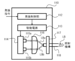
- FIG. 1 is a schematic diagram showing the configuration of a biological information detection device according to a first embodiment, which is a typical example of the present invention.
- 2 is a block diagram showing an example of the configuration of a laser oscillator included in the biological information detection device shown in FIG. 1.
- FIG. 2 is a block diagram showing an example of the configuration of a control unit included in the biological information detection device shown in FIG. 1.
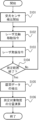
- FIG. 3 is a flowchart showing an overview of a biological information detection method according to the first embodiment.
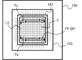
- FIG. 3 is a plan view showing an outline of an operation procedure in which a liquid biological object is irradiated with pulsed laser light in the biological information detection device according to the first embodiment.
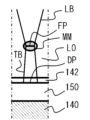
- FIG. 2 is a partial front view illustrating an outline of an operation procedure in which a liquid biological object is irradiated with pulsed laser light in the biological information detection device according to the first embodiment.
- FIG. 2 is a partial front view illustrating an outline of an operation procedure in which a liquid biological object is irradiated with pulsed laser light in the biological information detection device according to the first embodiment. It is a time series graph showing the relationship between various command signals and measurement data.
- FIG. 7 is a plan view showing an outline of an operation procedure in which a liquid biological object is irradiated with pulsed laser light in the biological information detection device according to the second embodiment.
- FIG. 7 is a partial front view showing an outline of an operation procedure in which a liquid biological object is irradiated with pulsed laser light in the biological information detection device according to the second embodiment.
- FIG. 7 is a partial front view showing an outline of an operation procedure in which a liquid biological object is irradiated with pulsed laser light in the biological information detection device according to the second embodiment.
- 7 is a flowchart showing an overview of a biological information detection method according to a second embodiment.
- FIG. 7 is a plan view showing an outline of an operation procedure in which a liquid biological object is irradiated with pulsed laser light in a biological information detection device according to a third embodiment.
- FIG. 7 is a partial front view showing an outline of an operation procedure in which a liquid biological object is irradiated with pulsed laser light in the biological information detection device according to the third embodiment.
- FIG. 7 is a partial front view showing an outline of an operation procedure in which a liquid biological object is irradiated with pulsed laser light in the biological information detection device according to the third embodiment. It is a time series graph showing the relationship between various command signals and measurement data.
- FIG. 7 is a partial cross-sectional view showing an outline of a measurement unit according to a modified example of the biological information detection device according to the third embodiment.
- FIG. 3 is a schematic diagram showing the configuration of a biological information detection device according to a fourth embodiment. It is a time series graph showing the relationship between various command signals and measurement data.
- 13 is a block diagram showing an example of the configuration of a laser oscillator included in the biological information detection device shown in FIG. 12.
- FIG. 12 is a block diagram showing an example of the configuration of a laser oscillator included
- liquid biological substance refers to liquid substances and secretions produced in the human body, such as blood, sweat, and lymph.
- substances to be measured include molecular compounds other than water contained in the liquid biological material.
- FIG. 1 is a schematic diagram showing the configuration of a biological information detection device according to a first embodiment, which is a typical example of the present invention.
- FIG. 2 is a block diagram showing an example of the configuration of a laser oscillator included in the biological information detection device shown in FIG. 1.
- FIG. 3 is a block diagram showing an example of the configuration of a control unit included in the biological information detection device shown in FIG. 1.
- the biological information detection device 100 includes, as an example, a laser oscillator 110 that oscillates a pulsed laser beam LB at an appropriate wavelength corresponding to the substance to be measured;
- An irradiation mechanism 120 that irradiates pulsed laser light LB to a liquid biological object LO in which a substance exists, a transport mechanism 130 that moves the position of the irradiation mechanism 120 in the XYZ directions, and a container 142 that accommodates the liquid biological object LO.
- It includes a sample holding mechanism 140 that moves the position in the direction, a light receiving sensor 150 that receives the detection laser light output from the liquid biological object LO, and a control unit 160 that controls the operation of each component.
- the laser oscillator 110 is a light source that outputs an appropriate wavelength (for example, a wavelength with high absorption efficiency) for detecting a substance to be measured (see symbols MM, etc. in FIG. 5C, which will be described later) contained in the liquid biological substance LO. be done. As an example, as shown in FIG.
- the laser oscillator 110 includes an oscillation control section 112 that performs control to oscillate the pulsed laser beam LB at a constant period T based on an oscillation signal from the control unit 160;
- a driving power source 113 that supplies driving power to the plurality of laser light sources 115a, 115b according to on/off signals from the laser light sources 115a, 115b, a support section 114 to which the laser light sources 115a, 115b are attached,
- a condenser lens 116 that condenses the pulsed laser beam LB, a wavelength adjustment section 117 that adjusts the wavelength of the emitted pulsed laser beam LB, and a transmission line 118 that transmits the condensed pulsed laser beam LB to the irradiation mechanism 120. (e.g. optical fiber).
- blood can be exemplified as the liquid biological substance LO
- lactic acid or “lactate” can be exemplified as a typical measurement target substance contained in this.
- the appropriate wavelength of the pulsed laser beam LB for detecting lactic acid or lactate is, for example, 1480 nm.
- the plurality of laser light sources 115a and 115b include light emitting diodes (LEDs) and semiconductor lasers (LD) arranged in an array, a laser oscillated by millimeter waves, submillimeter waves, or microwaves, or a free electron laser can be used.
- LEDs light emitting diodes
- LD semiconductor lasers
- a laser oscillated by millimeter waves, submillimeter waves, or microwaves, or a free electron laser can be used.
- the pulsed laser beam LB which has been condensed coaxially and increased in output to the wavelength adjustment section 117, the pulsed laser beam LB selected within a predetermined appropriate wavelength range is emitted to the transmission path 118.
- Ru As the wavelength adjustment section 117, a band pass filter or the like that selectively removes light outside the range of predetermined upper and lower limits can be exemplified.
- a case is illustrated in which two light sources are arranged as the plurality of laser light sources 115a and 115b, but a larger number (three or more) of laser light sources may be arranged in an array or on a circumference. It may be configured as follows. Furthermore, although a case has been shown in which driving power is directly supplied from the driving power source 113 to the plurality of laser light sources 115a and 115b, for example, an amplifier circuit (not shown) may be provided in the support portion 114 to supply driving power from the driving power source 113. The light may be amplified and supplied to the laser light sources 115a and 115b.
- the irradiation mechanism 120 is configured such that a pulsed laser beam LB is introduced from one end (upper end) side via a transmission line 118, and is focused to a predetermined beam diameter and beam cross section by a condensing lens (not shown) disposed inside. After the beam is shaped into a beam profile such as a shape, it is irradiated from the other end (lower end) toward the liquid biological substance LO housed in the container 142.
- the pulsed laser beam LB is shaped so that the beam spot has a circular cross section.
- the beam profile can be shaped into a polygonal shape. Alternatively, it is also possible to form it into an arbitrary shape such as a line shape.
- the transport mechanism 130 is configured as a linear drive body that moves relatively in three axes directions of X, Y, and Z that are orthogonal to each other, and the irradiation mechanism 120 is attached to one end of the linear drive body.
- the transport mechanism 130 may be configured as a 6-axis or 7-axis type industrial robot including a robot arm with the irradiation mechanism 120 attached to one end.
- the sample holding mechanism 140 is configured as a table that is movable in the three axis directions of XYZ shown in the figure while placing a container 142 containing a liquid biological substance LO containing a substance to be measured on its upper surface. Further, a light receiving sensor 150 is arranged between the upper surface of the sample holding mechanism 140 and the lower surface of the container 142 to detect transmitted light from the liquid biological substance LO.
- the container 142 that accommodates the liquid biological substance LO is made of a material that is transparent to the wavelength of the pulsed laser beam LB described above (that is, the irradiated pulsed laser beam LB is transmitted through).
- the pulsed laser light irradiated onto the liquid biological substance LO housed in the container 142 passes through the bottom surface of the container 142 as it is in the area where the substance to be measured does not exist and reaches the light receiving sensor 150. irradiation is detected.
- the control unit 160 includes, for example, a main control section 162 that outputs operation commands to each component of the biological information detection device 100, and a main control section 162 that outputs operation commands to each component of the biological information detection device 100, and a liquid biological object LO using detected values from a light receiving sensor.
- a quantity calculation unit 164 that calculates the amount of the substance to be measured contained in the substance to be measured, a display unit 166 that displays the calculated quantity of the substance to be measured and other various parameters, and corrects various parameters such as measurement conditions. and an input interface 168 through which information can be manually input.
- a main control section 162 is connected to the laser oscillator 110, the transport mechanism 130, and the sample holding mechanism 140 by wire or wirelessly, and exchanges signals with these peripheral devices to control the biological information detection apparatus 100. Control the entire operation.
- the main control unit 162 controls the oscillation from a predetermined measurement program to the laser oscillator 110, the transport mechanism 130, and the sample holding mechanism. It has a function of extracting operation information such as relative movement to 140, generating oscillation signal So and relative movement signal Sm for executing these operations, and outputting them to each component.
- the main control unit 162 outputs an oscillation signal So to a quantity calculation unit 164 (described later) in synchronization with the output to the laser oscillator 110, and receives the calculation result from the quantity calculation unit 164, and receives the calculation result of the quantity calculation unit 164. It also has a function of sending various parameters of the current biological information detection device 100 to the display unit 166 and displaying them.
- the quantity calculation unit 164 When the quantity calculation unit 164 receives the calculation signal Se corresponding to the start of calculation from the main control unit 162 which has received the start signal described above, the quantity calculation unit 164 continuously receives the detection signal Sd corresponding to the detection value at time t from the light receiving sensor 150. It has a function to store data. Further, the quantity calculation unit 164 receives the oscillation signal So from the main control unit 162 and cuts out section data D that matches the oscillation timing of the laser oscillator 110 from the time series data of the detection signal Sd detected by the light receiving sensor 150. It also has a function of calculating the amount of the substance to be measured contained in the liquid biological substance LO based on the section data D. The calculated amount of the substance to be measured is then sent to the main control section 162.
- FIG. 4 is a flowchart showing an overview of the biological information detection method according to the first embodiment.
- FIG. 5A is a plan view showing an outline of an operation procedure in which a liquid biological object is irradiated with pulsed laser light in the biological information detection device according to the first embodiment.
- FIGS. 5B and 5C are partial front views showing an outline of the operation procedure in which a liquid biological substance is irradiated with pulsed laser light in the biological information detection device according to the first embodiment.
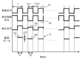
- FIG. 6 is a time series graph showing the relationship between various command signals and measurement data.
- the biological information detection method executed by the biological information detection device 100 when a start signal Ss corresponding to the start of measurement is input from the user through the input interface 168, The main control section 162 of the unit 160 instructs the amount calculation section 164 to start receiving the detection signal Sd from the light receiving sensor 150 (step S101). As a result, the quantity calculation unit 164 continuously receives and temporarily stores the detection signal Sd from the light receiving sensor 150 as time series data until the end of the operation shown in the flowchart.
- the main control unit 162 outputs a relative movement signal Sm to the transport mechanism 130 and the sample holding mechanism 140 based on a predetermined measurement program (step S102). As a result, the position and focal length at which the pulsed laser beam LB is irradiated onto the liquid biological object LO are determined.
- the main control unit 162 outputs an oscillation signal So to the laser oscillator 110 to emit the pulsed laser beam LB for a predetermined irradiation time Ton (step S103).
- the oscillation control unit 112 outputs the ON command signal Son to the drive power source 113 only during the irradiation time Ton, and the pulsed laser beam LB adjusted to a predetermined wavelength is output. is emitted.
- the main control unit 162 determines whether irradiation with the pulsed laser beam LB has been completed in all measurement ranges defined for the liquid biological substance LO in the container 142 based on the measurement program (step S104). That is, if it is determined in step S104 that irradiation in all measurement ranges has been completed, the main control unit 162 outputs a calculation signal Se to the volume calculation unit 164 as the measurement of the liquid biological substance LO has been completed, and thereafter The process advances to step S105.
- step S104 determines whether irradiation has been completed in all measurement ranges. If it is determined in step S104 that irradiation has not been completed in all measurement ranges, the process returns to step S102, and positioning and irradiation of the pulsed laser beam LB to the unfinished measurement ranges according to the measurement program are repeatedly performed. be done. As a result, detection of the substance to be measured is executed in all ranges (regions) of the liquid biological substance LO contained in the container 142 to be measured.
- FIGS. 5A to 5C a specific example of the operation procedure from step S102 to step S104 described above is shown. That is, as shown in FIG. 5A, a liquid biological substance LO is contained in a container 142 placed on a light receiving sensor 150 having a sensing surface on the upper surface, and the pulsed laser beam LB is collected in the liquid biological substance LO. A plurality of rectangular areas C are defined whose vertical and horizontal lengths correspond to the condensing diameter (spot diameter) of the light point FP.
- the measurement program further defines the irradiation start position Ps and the irradiation end position Pe of the pulsed laser beam LB, and also defines the irradiation start position Ps and the irradiation end position Pe.
- a scanning path for scanning in the X and Y directions is defined. Note that in the determination in step S104 of the flowchart shown in FIG. 4, it is determined whether the current irradiation position (focusing point FP) coincides with the irradiation end position Pe on the scanning path.
- the relationship between the presence or absence of the substance to be measured MM and the detection signal from the light receiving sensor 150 at the irradiation position of the pulsed laser beam LB (focusing point FP) will be described below.
- the pulsed laser beam LB passes through the liquid biological substance LO and the container 142.
- transmitted light TB corresponding to the output of the irradiated pulsed laser beam LB is detected at the light receiving point DP of the light receiving sensor 150.
- FIG. 5C illustrates a case where the substance to be measured MM is larger than the condensing diameter of the condensing point FP of the pulsed laser beam LB, the same tendency is shown even when it is smaller than the condensing diameter. .
- the amount calculation section 164 that received the calculation signal from the main control section 162 calculates the detection from the light receiving sensor 150 corresponding to the section in which the oscillation signal So from the main control section 162 was being received, as shown in FIG.
- section data D is extracted (step S105).
- the irradiation time Ton and non-irradiation time Toff of the oscillation signal So are collectively defined as one period T.
- the quantity calculation unit 164 calculates the quantity of the measurement target substance MM with respect to the liquid biological substance LO based on the extracted section data D.
- the section data D extracted in step S105 is, for example, the reference data Ds when the measurement target substance MM is not detected (non-detection section Tn) (the state shown in FIG. 5B), It includes output values at two levels: detection data Dd (state shown in FIG. 5C) when the substance to be measured MM is detected (detection section Td).
- the quantity calculation unit 164 integrates the number of detection data Dd in the entire section data D, and outputs it to the main control unit 162 as the “quantity” of the substance to be measured MM. The operation ends (step S106).
- the amount of the substance to be measured MM may be calculated not as an integrated number but as a ratio to the whole. Further, a threshold value may be set for the difference ⁇ D between the reference data Ds and the detection data Dd, and the difference ⁇ D between the reference data Ds and the detection data Dd may be determined to be “detected” if it exceeds the predetermined threshold value.
- the biological information detection device and biological information detection method outputs an oscillation command to the laser oscillator to oscillate pulsed laser light at a constant cycle, and receives the light.
- the detection signal from the sensor is cut out as interval data at a time corresponding to the above-mentioned fixed period, and the amount of the substance to be measured in the liquid biological substance is calculated based on the interval data, so that it is possible to calculate the amount of the substance to be measured in the liquid biological substance.
- Measurement data of the substance to be measured can be obtained non-invasively with low noise.
- FIGS. 7A to 8 an embodiment of a biological information detection device and a biological information detection method according to a second embodiment, which is another example of the present invention, will be described using FIGS. 7A to 8.
- the second embodiment in the schematic diagrams shown in FIGS. 1 to 6, parts that can have the same or common configuration as those in the first embodiment are denoted by the same reference numerals. The explanation of the repetition of is omitted.
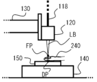
- FIG. 7A is a plan view illustrating an outline of an operation procedure in which a liquid biological object is irradiated with pulsed laser light in the biological information detection device according to the second embodiment.
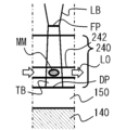
- FIGS. 7B and 7C are partial front views showing an outline of the operation procedure in which a liquid biological substance is irradiated with pulsed laser light in the biological information detection device according to the second embodiment.
- FIG. 8 is a flowchart showing an overview of the biological information detection method according to the second embodiment.
- a measurement method using a container 142 containing the liquid biological substance LO is used.
- a method is used in which a blood vessel or the like is directly irradiated with a pulsed laser beam LB for direct measurement while blood is flowing inside a living organism such as a human being. That is, as shown in FIG. 7A, the pulsed laser beam LB is placed on the light-receiving sensor 150 having the sensing surface on the upper surface, and the end portion (for example, the finger 240) through which the pulsed laser beam LB applied to the human body is relatively easily transmitted. The light LB is irradiated toward the finger 240.
- the substance to be measured MM does not exist at the focal point FP of the irradiated pulsed laser beam LB or on its extension.
- the pulsed laser beam LB passes through the finger 240 including the blood vessel 242, the transmitted light TB corresponding to the output of the irradiated pulsed laser beam LB is detected at the light receiving point DP of the light receiving sensor 150.
- the detection signal Sd from the light receiving sensor 150 is received while irradiating the pulsed laser beam LB for a predetermined period of time by on/off control with a constant period T.
- the amount calculation unit 164 is instructed to start receiving the detection signal Sd from the light receiving sensor 150 (step S201). As a result, the quantity calculation unit 164 continuously receives and temporarily stores the detection signal Sd from the light receiving sensor 150 as time series data until the end of the operation shown in the flowchart.
- the main control unit 162 outputs an oscillation signal So to the laser oscillator 110 to emit the pulsed laser beam LB for a predetermined irradiation time Ton based on a predetermined measurement program (step S202).
- the oscillation control unit 112 outputs the on-command signal Son to the drive power source 113 only during the irradiation time Ton, as in the first embodiment.
- a pulsed laser beam LB whose wavelength is adjusted is emitted.
- the main control unit 162 determines whether or not the irradiation of the pulsed laser beam LB with the constant period T has ended for a predetermined period, based on the measurement program described above (step S203). That is, in step S203, if it is determined that the predetermined number of cycles of irradiation has been completed, the main control unit 162 outputs the calculation signal Se to the amount calculation unit 164 as the measurement of the liquid biological substance LO has been completed, and the subsequent The process advances to step S204.
- step S203 if it is determined in step S203 that the predetermined number of cycles of irradiation has not been completed, the process returns to step S202 and repeats the irradiation of one cycle of pulsed laser beam LB. As a result, a detection operation is performed for the substance to be measured during a predetermined period of time of the liquid biological substance (blood) LO that continuously flows through the blood vessel 242 of the finger 240 .
- the quantity calculation unit 164 that has received the calculation signal from the main control unit 162 receives the calculation signal from the light receiving sensor 150 corresponding to the section in which it has received the oscillation signal So from the main control unit 162, as in the first embodiment.
- section data D is extracted (step S204). Thereby, it is possible to narrow down only the data in the section corresponding to the irradiation time Ton during which the pulsed laser beam LB was irradiated in the detection signal Sd.
- the quantity calculation unit 164 calculates the quantity of the measurement target substance MM with respect to the liquid biological substance LO based on the extracted section data D, as in the case of the first embodiment. Thereby, after measuring the time-series data in a predetermined number of cycles, the quantity calculation unit 164 integrates the number of detection data Dd in the entire section data D, and sends the result to the main control unit 162 as the “quantity” of the substance to be measured MM. It outputs and ends the operation (step S205).
- the biological information detection device and biological information detection method according to the second embodiment have the effects described in the first embodiment, and can also be applied to a typical example of a liquid biological material.
- a liquid biological material containing the substance to be measured is prepared from the human body, etc. There is no need to obtain the data, which reduces the burden during measurement.
- the step of moving the pulsed laser beam relative to the container containing the liquid biological substance LO to be measured is not required, the overall measurement time can also be shortened.
- FIGS. 9A to 11 embodiments of a biological information detection device and a biological information detection method according to a third embodiment, which is still another example of the present invention, will be described using FIGS. 9A to 11.
- the third embodiment in the schematic diagrams shown in FIGS. 1 to 8, the same or common configurations as those in the first embodiment and the second embodiment can be adopted. A description of these repetitions will be omitted by attaching reference numerals.
- FIG. 9A is a plan view showing an outline of an operation procedure in which a liquid biological object is irradiated with pulsed laser light in the biological information detection device according to the third embodiment.
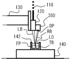
- FIGS. 9B and 9C are a plan view and a partial front view illustrating an outline of the operation procedure for irradiating a liquid biological object with pulsed laser light in the biological information detection device according to the third embodiment.
- FIG. 10 is a time series graph showing the relationship between various command signals and measurement data.
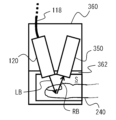
- FIG. 11 is a partial sectional view showing an outline of a measurement unit according to a modification of the biological information detection device according to the third embodiment.
- a measurement target included in the liquid biological object LO is used in contrast to the measurement method in which the light receiving sensor 150 detects transmitted light from the liquid biological object LO in the first embodiment.
- a method of measuring reflected light from the substance MM is used. That is, as shown in FIG. 9A, a liquid biological substance LO is contained in a container 142 placed on a sample holding mechanism 140, and as in the case of the first embodiment, a predetermined measurement of the liquid biological substance LO is performed.
- a pulsed laser beam LB is irradiated onto the range.
- the light receiving sensor 350 attached to the irradiation mechanism 120 detects the reflected light RB reflected by the measurement target substance MM contained in the liquid biological object LO. That is, as shown in FIG. 9B, for example, if the substance to be measured MM does not exist at the focal point FP of the irradiated pulsed laser beam LB or its extension, the pulsed laser beam LB passes through the liquid biological substance LO and the container 142. Therefore, the light receiving sensor 350 detects only a detection value based on the amount of light around the device.
- a detection signal Sd having a large detection value is received in the section where the light receiving sensor 350 detects the reflected light RB.
- the quantity calculation section 164 extracts section data D by cutting out the section of the detection signal Sd from the light receiving sensor 150 that corresponds to the section in which the oscillation signal So from the main control section 162 was being received.
- the quantity calculation unit 164 calculates the quantity of the measurement target substance MM with respect to the liquid biological substance LO based on the extracted section data D.
- the extracted section data D includes, for example, reference data Ds when the target substance MM is not detected (non-detection interval Tn), and reference data Ds when the target substance MM is detected (non-detection interval Tn). Detection data Dd of section Td) and output values of two levels are included.
- the quantity calculation unit 164 integrates the number of detection data Dd in the entire section data D, and sends the calculation result to the main control unit 162 as the “quantity” of the substance MM to be measured. Output.
- the amount of the measurement target substance MM is calculated by detecting the reflected light RB of the pulsed laser beam LB with respect to the measurement target substance MM. Therefore, as a modification of the third embodiment, it is possible to adopt a configuration of a measurement unit having a more compact size.
- the measurement unit 360 includes a cylindrical housing part 362 that accommodates a part of the living body, such as the finger 240, into which the liquid living body LO flows, and a cylindrical housing part 362 that accommodates a part of the living body, such as the finger 240, into which the liquid living body LO flows.
- An example of a configuration includes an irradiation mechanism 120 that irradiates the pulsed laser beam LB, and a light receiving sensor 350 that detects reflected light of the pulsed laser beam LB. This allows detection of the amount of light associated with the surrounding environment of the measurement unit 360 to be kept to a minimum, making it possible to further improve measurement accuracy.
- the biological information detection device and biological information detection method according to the third embodiment in addition to the effects described in the first embodiment, can improve the measurement target substance contained in the liquid biological substance.
- detection of the amount of light associated with the surrounding environment can be kept to a minimum, making it possible to further improve measurement accuracy.
- FIGS. 12 to 14 embodiments of a biological information detection device and a biological information detection method according to a fourth embodiment, which is still another example of the present invention, will be described using FIGS. 12 to 14.
- the same reference numerals are given to parts that can have the same or common configurations as those in the first to third embodiments. A repeated explanation of these steps will be omitted.
- FIG. 12 is a schematic diagram showing the configuration of a biological information detection device according to the fourth embodiment.
- FIG. 13 is a time series graph showing the relationship between various command signals and measurement data.
- FIG. 14 is a block diagram showing an example of the configuration of a laser oscillator included in the biological information detection device shown in FIG. 12.
- the biological information detection device 400 according to the fourth embodiment has a plurality of laser oscillators 410a and 410b that output pulsed laser beams LBa and LBb set to different appropriate wavelengths corresponding to different measurement target substances. This embodiment is different from the first embodiment. Thereby, the biological information detection device 400 according to the fourth embodiment can obtain the amounts of the plurality of measurement target substances MM1 and MM2 from a single liquid biological substance LO.
- the biological information detection device 400 includes a laser oscillator 410a that oscillates pulsed laser light LBa at an appropriate wavelength corresponding to the first measurement target substance. , a laser oscillator 410b that oscillates a pulsed laser beam LBb at an appropriate wavelength corresponding to the second substance to be measured, and a liquid biological substance in which the first substance to be measured and the second substance to be measured are present.
- An irradiation mechanism 120 that irradiates the LO with pulsed laser beams LBa and LBb, a transport mechanism 130 that moves the position of the irradiation mechanism 120 in the XYZ directions, and a sample that moves the position of the container 142 containing the liquid biological substance LO in the XYZ directions. It includes a holding mechanism 140, a light receiving sensor 150 that receives detection laser light output from the liquid biological material LO, and a control unit 160 that controls the operation of each component.
- lactic acid or "lactate” can be exemplified as the first measurement target substance MM1 contained in the liquid biological substance LO.
- the appropriate wavelength of the pulsed laser beam LBa for detecting the lactic acid or lactate is, for example, 1480 nm, as in the first embodiment.
- pyruvic acid can be exemplified as the second measurement target substance MM2 contained in the liquid biological substance LO.
- the appropriate wavelength of the pulsed laser beam LBb for detecting the pyruvic acid is, for example, 1462 nm.
- the pulsed laser beams LBa and LBb output from the laser oscillators 410a and 410b are introduced from one end (upper end) side of the irradiation mechanism 120 via transmission lines 418a and 418b, respectively. Then, the pulsed laser beams LBa and LBb are shaped into a coaxial beam profile by a condensing optical system (not shown) disposed inside the irradiation mechanism 120, and then stored in the container 142 from the other end (lower end) side.
- the liquid biological substance LO is irradiated. Note that in the fourth embodiment as well, it is possible to shape the beam spots of the pulsed laser beams LBa and LBb into a beam profile having an arbitrary shape such as a polygon or a line shape.
- the relationship between the detection signal Sd and various signals in the light-receiving sensor 150 obtained by such a configuration is as shown in FIG. 13 as an example.
- This mode includes two detection sections T2d.
- the quantity calculation section 164 that receives the calculation signal from the main control section 162 receives the section of the detection signal Sd corresponding to the section in which it was receiving the oscillation signal S1o and the oscillation signal S2o.
- the first section data D1 and the second section data D2 are extracted by cutting out the section of the detection signal Sd corresponding to the section in which the detection signal Sd has been detected.
- the amount calculation unit 164 calculates the amounts of the measurement target substances MM1 and MM2 with respect to the liquid biological substance LO based on the extracted first section data D1 and second section data D2.
- the extracted first section data D1 and second section data D2 are, for example, standard data Ds when the measurement target substances MM1 and MM2 are not detected (non-detection section Tn), and measurement data Ds. It includes output values at two levels: detection data D1d and D2d when target substances MM1 and MM2 are detected.
- the quantity calculation unit 164 integrates the numbers of detection data D1d and D2d in the entire first section data D1 and second section data D2, and are output to the main control unit 162 as respective "amounts".
- the amounts of the substances to be measured MM1 and MM2 may be calculated not as an integrated number but as a ratio to the whole.
- a threshold value may be set for the difference ⁇ D1 or ⁇ D2, and a value exceeding a predetermined threshold value may be determined to be "detected.”
- a biological information detection device 400 according to a modification of the fourth embodiment includes, as an example, one in which the two laser oscillators 410a and 410b shown in FIG. 12 are configured as a single laser oscillator 410.
- the laser oscillator 410 includes an oscillation control section 112, a drive power source 113, a support section 114 to which a plurality of laser light sources 415a and 415b are attached, and a pulsed laser beam emitted from the laser light source 415a.
- the plurality of laser light sources 415a and 415b a plurality of light emitting diodes (LEDs) or semiconductor lasers (LDs) arranged in an array to achieve high output can be used.
- an amplifier circuit (not shown) may be separately provided to amplify and supply the driving power from the driving power source 113 to the plurality of laser light sources 415a and 415b.
- the biological information detection device 400 according to the fourth embodiment, the case where two different pulsed laser beams LBa and LBb are used to detect the two measurement target substances MM1 and MM2 is illustrated, but three or more pulsed laser beams LBa and LBb are used. In order to detect a substance to be measured, it is also possible to apply a combination of pulsed laser beams with three or more different wavelengths.
- the biological information detection device and biological information detection method according to the fourth embodiment in addition to the effects described in the first embodiment, can achieve different appropriateness corresponding to a plurality of substances to be measured. Since the detection is performed using a plurality of laser oscillators that output pulsed laser light with a set wavelength, it is possible to simultaneously obtain quantities of a plurality of measurement target substances from a single liquid biological substance.
- any component of the embodiments may be modified or any component of the embodiments may be omitted.
- the specific examples shown in the first to fourth embodiments may be applied by combining their respective characteristics.
- Biological information detection device 110 410, 410a, 410b Laser oscillator 112 Oscillation control section 113 Drive power source 114 Support section 115a, 115b, 415a, 415b Laser light source 116, 416a, 416b Condensing lens 117, 417a, 417b Wavelength adjustment Sections 118, 418a, 418b Transmission path 120 Irradiation mechanism 130 Transport mechanism 140 Sample holding mechanism 142 Container 150, 350 Light receiving sensor 160 Control unit 162 Main control section 164 Amount calculation section 166 Display section 168 Input interface 240 Finger 242 Blood vessel 360 Measurement unit 362 Storage section
Landscapes
- Health & Medical Sciences (AREA)
- Life Sciences & Earth Sciences (AREA)
- Physics & Mathematics (AREA)
- Engineering & Computer Science (AREA)
- Pathology (AREA)
- General Health & Medical Sciences (AREA)
- Biomedical Technology (AREA)
- Spectroscopy & Molecular Physics (AREA)
- Chemical & Material Sciences (AREA)
- Molecular Biology (AREA)
- Biophysics (AREA)
- General Physics & Mathematics (AREA)
- Analytical Chemistry (AREA)
- Biochemistry (AREA)
- Immunology (AREA)
- Heart & Thoracic Surgery (AREA)
- Veterinary Medicine (AREA)
- Public Health (AREA)
- Animal Behavior & Ethology (AREA)
- Surgery (AREA)
- Medical Informatics (AREA)
- Optics & Photonics (AREA)
- Food Science & Technology (AREA)
- Medicinal Chemistry (AREA)
- Hematology (AREA)
- Urology & Nephrology (AREA)
- Nuclear Medicine, Radiotherapy & Molecular Imaging (AREA)
- Radiology & Medical Imaging (AREA)
- Investigating Or Analysing Materials By Optical Means (AREA)
- Measurement Of The Respiration, Hearing Ability, Form, And Blood Characteristics Of Living Organisms (AREA)
- Measuring Pulse, Heart Rate, Blood Pressure Or Blood Flow (AREA)
Abstract
Description
図1は、本発明の代表的な一例である第1の実施形態による生体情報検出装置の構成を示す概略図である。また、図2は、図1で示した生体情報検出装置に含まれるレーザ発振器の構成の一例を示すブロック図である。また、図3は、図1で示した生体情報検出装置に含まれる制御ユニットの構成の一例を示すブロック図である。
次に、図7A~図8を用いて、本発明の別の一例である第2の実施形態による生体情報検出装置及び生体情報検出方法の実施態様について説明する。なお、第2の実施形態においては、図1~図6に示した概略図等において、第1の実施形態と同一あるいは共通の構成を採用し得るものについては、同一の符号を付してこれらの繰り返しの説明は省略する。
次に、図9A~図11を用いて、本発明のさらに別の一例である第3の実施形態による生体情報検出装置及び生体情報検出方法の実施態様について説明する。なお、第3の実施形態においては、図1~図8に示した概略図等において、第1の実施形態及び第2の実施形態と同一あるいは共通の構成を採用し得るものについては、同一の符号を付してこれらの繰り返しの説明は省略する。
次に、図12~図14を用いて、本発明のさらに別の一例である第4の実施形態による生体情報検出装置及び生体情報検出方法の実施態様について説明する。なお、第4の実施形態においては、図1~図11に示した概略図等において、第1~第3の実施形態と同一あるいは共通の構成を採用し得るものについては、同一の符号を付してこれらの繰り返しの説明は省略する。
110、410、410a、410b レーザ発振器
112 発振制御部
113 駆動電源
114 支持部
115a、115b、415a、415b レーザ光源
116、416a、416b 集光レンズ
117、417a、417b 波長調整部
118、418a、418b 伝送路
120 照射機構
130 搬送機構
140 サンプル保持機構
142 容器
150、350 受光センサ
160 制御ユニット
162 主制御部
164 分量演算部
166 表示部
168 入力インターフェース
240 指
242 血管
360 測定ユニット
362 収容部
Claims (10)
- 測定対象物質に対応した適正波長で発振されたパルスレーザ光を発振するレーザ発振器と、前記測定対象物質が内部に存在する液状生体物に前記パルスレーザ光を照射する照射機構と、前記液状生体物から出力される検出レーザ光を受光する受光センサと、各構成要素の動作を制御する制御ユニットと、を含む生体情報検出装置であって、
前記制御ユニットは、一定周期で前記パルスレーザ光を発振するように前記レーザ発振器に対して発振指令を出力し、前記受光センサからの検出信号を前記一定周期に対応する時間での区間データとして切り出し、前記区間データに基づいて前記液状生体物中の前記測定対象物質の分量を演算する
生体情報検出装置。 - 前記測定対象物質は乳酸又は乳酸塩であって、前記適正波長は1420nmである
請求項1に記載の生体情報検出装置。 - 前記パルスレーザ光は、流動中の前記液状生体物に向けて照射される
請求項1又は2に記載の生体情報検出装置。 - 前記受光センサは、前記パルスレーザ光の反射光を受光するように構成されている
請求項1~3のいずれか1項に記載の生体情報検出装置。 - 前記測定対象物質は複数であって、
前記レーザ発振器を前記複数の測定対象物質ごとに複数含む
請求項1~4のいずれか1項に記載の生体情報検出装置。 - 測定対象物質に対応した適正波長で発振されたパルスレーザ光を前記測定対象物質が内部に存在する液状生体物に照射し、前記液状生体物から出力される検出レーザ光を受光センサで受光して前記測定対象物質の前記液状生体物中の分量を取得する生体情報検出方法であって、
前記パルスレーザ光は一定周期で発振され、前記受光センサからの検出信号を前記一定周期に対応する時間での区間データとして切り出し、前記区間データに基づいて前記分量を演算する
生体情報検出方法。 - 前記測定対象物質は乳酸又は乳酸塩であって、前記適正波長は1420nmである
請求項6に記載の生体情報検出方法。 - 前記パルスレーザ光は、流動中の前記液状生体物に向けて照射される
請求項6又は7に記載の生体情報検出方法。 - 前記パルスレーザ光は反射光を前記検出レーザ光として受光する
請求項6~8のいずれか1項に記載の生体情報検出方法。 - 前記測定対象物質は複数であって、
前記パルスレーザ光は前記複数の測定対象物質ごとに複数照射される
請求項6~9のいずれか1項に記載の生体情報検出方法。
Priority Applications (6)
| Application Number | Priority Date | Filing Date | Title |
|---|---|---|---|
| CN202280038728.6A CN117858662A (zh) | 2022-08-09 | 2022-08-09 | 生物体信息检测装置以及生物体信息检测方法 |
| EP22940935.4A EP4353150B1 (en) | 2022-08-09 | 2022-08-09 | Biological information detection device and biological information detection method |
| JP2022568396A JP7290900B1 (ja) | 2022-08-09 | 2022-08-09 | 生体情報検出装置 |
| US18/562,427 US12474259B2 (en) | 2022-08-09 | 2022-08-09 | Biological information detection device and biological information detection method |
| PCT/JP2022/030509 WO2024034038A1 (ja) | 2022-08-09 | 2022-08-09 | 生体情報検出装置及び生体情報検出方法 |
| TW112129173A TW202410858A (zh) | 2022-08-09 | 2023-08-03 | 生體資訊檢測裝置及生體資訊檢測方法 |
Applications Claiming Priority (1)
| Application Number | Priority Date | Filing Date | Title |
|---|---|---|---|
| PCT/JP2022/030509 WO2024034038A1 (ja) | 2022-08-09 | 2022-08-09 | 生体情報検出装置及び生体情報検出方法 |
Publications (1)
| Publication Number | Publication Date |
|---|---|
| WO2024034038A1 true WO2024034038A1 (ja) | 2024-02-15 |
Family
ID=86721517
Family Applications (1)
| Application Number | Title | Priority Date | Filing Date |
|---|---|---|---|
| PCT/JP2022/030509 Ceased WO2024034038A1 (ja) | 2022-08-09 | 2022-08-09 | 生体情報検出装置及び生体情報検出方法 |
Country Status (6)
| Country | Link |
|---|---|
| US (1) | US12474259B2 (ja) |
| EP (1) | EP4353150B1 (ja) |
| JP (1) | JP7290900B1 (ja) |
| CN (1) | CN117858662A (ja) |
| TW (1) | TW202410858A (ja) |
| WO (1) | WO2024034038A1 (ja) |
Families Citing this family (2)
| Publication number | Priority date | Publication date | Assignee | Title |
|---|---|---|---|---|
| CN119213297A (zh) * | 2023-04-27 | 2024-12-27 | 株式会社藤田医科器械 | 生物体信息检测装置以及生物体信息检测方法 |
| WO2024257283A1 (ja) * | 2023-06-14 | 2024-12-19 | 株式会社フジタ医科器械 | 分量検出装置及び分量検出方法、並びに細胞培養システム |
Citations (6)
| Publication number | Priority date | Publication date | Assignee | Title |
|---|---|---|---|---|
| JPH09126995A (ja) * | 1995-08-30 | 1997-05-16 | Kdk Corp | 生体中の乳酸測定方法及び測定装置 |
| JP2002165797A (ja) * | 2000-12-01 | 2002-06-11 | Seiko Instruments Inc | 運動能力測定装置 |
| JP2002168862A (ja) * | 2000-12-04 | 2002-06-14 | Terumo Corp | 体液測定装置 |
| JP2010526646A (ja) | 2007-05-11 | 2010-08-05 | シグメッド,インコーポレーティッド | 生理学的パラメータの非侵襲的特徴決定 |
| JP2020520768A (ja) | 2017-05-22 | 2020-07-16 | ブロリス センサー テクノロジー, ユーエイビーBrolis Sensor Technology, Uab | 血液成分濃度レベルのリアルタイムモニタリング用の波長可変ハイブリッドiii−v/ivレーザセンサシステムオンチップ |
| JP2021180796A (ja) * | 2020-05-20 | 2021-11-25 | 日本光電工業株式会社 | パルスフォトメータ、パルスフォトメトリシステム、およびコンピュータプログラム |
Family Cites Families (5)
| Publication number | Priority date | Publication date | Assignee | Title |
|---|---|---|---|---|
| EP0762109A3 (en) | 1995-08-30 | 1997-09-17 | Kyoto Daiichi Kagaku Kk | Method and device for measuring lactic acid in an organism |
| US7426035B2 (en) * | 2003-09-22 | 2008-09-16 | Celight, Inc. | System and method for chemical sensing using trace gas detection |
| JP2010125147A (ja) | 2008-11-28 | 2010-06-10 | Hamamatsu Photonics Kk | 生体計測装置 |
| CN106331442B (zh) | 2015-07-02 | 2021-01-15 | 松下知识产权经营株式会社 | 摄像装置 |
| EP4224147A4 (en) * | 2020-09-30 | 2024-03-13 | Light Touch Technology Incorporated | DEVICE FOR MEASURING THE CONCENTRATION OF A SUBSTANCE IN BLOOD AND METHOD FOR MEASURING THE CONCENTRATION OF A SUBSTANCE IN BLOOD |
-
2022
- 2022-08-09 CN CN202280038728.6A patent/CN117858662A/zh active Pending
- 2022-08-09 EP EP22940935.4A patent/EP4353150B1/en active Active
- 2022-08-09 US US18/562,427 patent/US12474259B2/en active Active
- 2022-08-09 WO PCT/JP2022/030509 patent/WO2024034038A1/ja not_active Ceased
- 2022-08-09 JP JP2022568396A patent/JP7290900B1/ja active Active
-
2023
- 2023-08-03 TW TW112129173A patent/TW202410858A/zh unknown
Patent Citations (6)
| Publication number | Priority date | Publication date | Assignee | Title |
|---|---|---|---|---|
| JPH09126995A (ja) * | 1995-08-30 | 1997-05-16 | Kdk Corp | 生体中の乳酸測定方法及び測定装置 |
| JP2002165797A (ja) * | 2000-12-01 | 2002-06-11 | Seiko Instruments Inc | 運動能力測定装置 |
| JP2002168862A (ja) * | 2000-12-04 | 2002-06-14 | Terumo Corp | 体液測定装置 |
| JP2010526646A (ja) | 2007-05-11 | 2010-08-05 | シグメッド,インコーポレーティッド | 生理学的パラメータの非侵襲的特徴決定 |
| JP2020520768A (ja) | 2017-05-22 | 2020-07-16 | ブロリス センサー テクノロジー, ユーエイビーBrolis Sensor Technology, Uab | 血液成分濃度レベルのリアルタイムモニタリング用の波長可変ハイブリッドiii−v/ivレーザセンサシステムオンチップ |
| JP2021180796A (ja) * | 2020-05-20 | 2021-11-25 | 日本光電工業株式会社 | パルスフォトメータ、パルスフォトメトリシステム、およびコンピュータプログラム |
Non-Patent Citations (1)
| Title |
|---|
| See also references of EP4353150A4 |
Also Published As
| Publication number | Publication date |
|---|---|
| EP4353150A4 (en) | 2025-01-22 |
| JP7290900B1 (ja) | 2023-06-14 |
| US12474259B2 (en) | 2025-11-18 |
| US20250020583A1 (en) | 2025-01-16 |
| EP4353150B1 (en) | 2025-12-24 |
| JPWO2024034038A1 (ja) | 2024-02-15 |
| TW202410858A (zh) | 2024-03-16 |
| EP4353150A1 (en) | 2024-04-17 |
| EP4353150C0 (en) | 2025-12-24 |
| CN117858662A (zh) | 2024-04-09 |
Similar Documents
| Publication | Publication Date | Title |
|---|---|---|
| US5575285A (en) | Apparatus for measuring oxygen saturation | |
| EP0426358B1 (en) | A non-invasive method and apparatus for measuring blood chemical concentration | |
| CA2704789C (en) | Optical sensor for determining the concentration of an analyte | |
| CN101808570B (zh) | 血氧计 | |
| JP7290900B1 (ja) | 生体情報検出装置 | |
| JP4973751B2 (ja) | 生体成分測定装置 | |
| CN114469333B (zh) | 消融导管、激光消融系统及血管内激光斑块消融方法 | |
| EP3460453A2 (en) | Frequency domain-based multi-wavelength biometric signal analysis apparatus and method thereof | |
| JP7336818B1 (ja) | 生体情報検出装置及び生体情報検出方法 | |
| US20050277817A1 (en) | Noninvasive measurement system for monitoring activity condition of living body | |
| JP3635331B2 (ja) | 物質計測装置 | |
| US20240353320A1 (en) | Optical system and methods of use | |
| KR101818184B1 (ko) | 체내 삽입형 의료기기를 이용한 레이저 유도 열 스트레인 영상 획득 시스템, 방법, 및 레이저 유도 열 스트레인 영상 획득용 체내 삽입형 의료기기 | |
| JPH01250271A (ja) | 医用レーザ照射装置 | |
| CN112351735B (zh) | 血糖值变化量测定装置 | |
| JP2010502980A (ja) | 光断層撮影システムにおける変位検出 | |
| WO2016147706A1 (ja) | 光音響計測装置及びプローブ | |
| JP2005074188A (ja) | 生体情報測定方法及び生体情報測定装置 | |
| US20240328930A1 (en) | Method for calibrating an optical system | |
| CN117918836A (zh) | 一种无创光电反射式生理参数测量的传感器及可穿戴装置 | |
| WO2024257283A1 (ja) | 分量検出装置及び分量検出方法、並びに細胞培養システム | |
| JP2017060621A (ja) | 光音響画像化装置 | |
| KR930011586B1 (ko) | 난-인베이시브 혈당농도 측정방법 및 그 장치 | |
| WO2022079975A1 (ja) | 測定装置、測定方法、およびプログラム | |
| JP2003254899A (ja) | 生体光計測装置 |
Legal Events
| Date | Code | Title | Description |
|---|---|---|---|
| ENP | Entry into the national phase |
Ref document number: 2022568396 Country of ref document: JP Kind code of ref document: A |
|
| WWE | Wipo information: entry into national phase |
Ref document number: 18562427 Country of ref document: US |
|
| WWE | Wipo information: entry into national phase |
Ref document number: 202280038728.6 Country of ref document: CN |
|
| ENP | Entry into the national phase |
Ref document number: 2022940935 Country of ref document: EP Effective date: 20231114 |
|
| NENP | Non-entry into the national phase |
Ref country code: DE |
|
| WWG | Wipo information: grant in national office |
Ref document number: 18562427 Country of ref document: US |
|
| WWG | Wipo information: grant in national office |
Ref document number: 2022940935 Country of ref document: EP |