WO2024034224A1 - 乗用車用空気入りラジアルタイヤ - Google Patents
乗用車用空気入りラジアルタイヤ Download PDFInfo
- Publication number
- WO2024034224A1 WO2024034224A1 PCT/JP2023/019384 JP2023019384W WO2024034224A1 WO 2024034224 A1 WO2024034224 A1 WO 2024034224A1 JP 2023019384 W JP2023019384 W JP 2023019384W WO 2024034224 A1 WO2024034224 A1 WO 2024034224A1
- Authority
- WO
- WIPO (PCT)
- Prior art keywords
- tire
- carcass
- width direction
- belt
- cord
- Prior art date
- Legal status (The legal status is an assumption and is not a legal conclusion. Google has not performed a legal analysis and makes no representation as to the accuracy of the status listed.)
- Ceased
Links
Images





Classifications
-
- B—PERFORMING OPERATIONS; TRANSPORTING
- B60—VEHICLES IN GENERAL
- B60C—VEHICLE TYRES; TYRE INFLATION; TYRE CHANGING; CONNECTING VALVES TO INFLATABLE ELASTIC BODIES IN GENERAL; DEVICES OR ARRANGEMENTS RELATED TO TYRES
- B60C9/00—Reinforcements or ply arrangement of pneumatic tyres
- B60C9/02—Carcasses
- B60C9/04—Carcasses the reinforcing cords of each carcass ply arranged in a substantially parallel relationship
- B60C9/08—Carcasses the reinforcing cords of each carcass ply arranged in a substantially parallel relationship the cords extend transversely from bead to bead, i.e. radial ply
- B60C9/09—Carcasses the reinforcing cords of each carcass ply arranged in a substantially parallel relationship the cords extend transversely from bead to bead, i.e. radial ply combined with other carcass plies having cords extending diagonally from bead to bead, i.e. combined radial ply and bias angle ply
-
- B—PERFORMING OPERATIONS; TRANSPORTING
- B60—VEHICLES IN GENERAL
- B60C—VEHICLE TYRES; TYRE INFLATION; TYRE CHANGING; CONNECTING VALVES TO INFLATABLE ELASTIC BODIES IN GENERAL; DEVICES OR ARRANGEMENTS RELATED TO TYRES
- B60C9/00—Reinforcements or ply arrangement of pneumatic tyres
- B60C9/02—Carcasses
- B60C9/04—Carcasses the reinforcing cords of each carcass ply arranged in a substantially parallel relationship
- B60C9/08—Carcasses the reinforcing cords of each carcass ply arranged in a substantially parallel relationship the cords extend transversely from bead to bead, i.e. radial ply
-
- B—PERFORMING OPERATIONS; TRANSPORTING
- B60—VEHICLES IN GENERAL
- B60C—VEHICLE TYRES; TYRE INFLATION; TYRE CHANGING; CONNECTING VALVES TO INFLATABLE ELASTIC BODIES IN GENERAL; DEVICES OR ARRANGEMENTS RELATED TO TYRES
- B60C3/00—Tyres characterised by the transverse section
- B60C3/04—Tyres characterised by the transverse section characterised by the relative dimensions of the section, e.g. low profile
-
- B—PERFORMING OPERATIONS; TRANSPORTING
- B60—VEHICLES IN GENERAL
- B60C—VEHICLE TYRES; TYRE INFLATION; TYRE CHANGING; CONNECTING VALVES TO INFLATABLE ELASTIC BODIES IN GENERAL; DEVICES OR ARRANGEMENTS RELATED TO TYRES
- B60C9/00—Reinforcements or ply arrangement of pneumatic tyres
- B60C9/02—Carcasses
- B60C9/0207—Carcasses comprising an interrupted ply, i.e. where the carcass ply does not continuously extend from bead to bead but is interrupted, e.g. at the belt area, into two or more portions of the same ply
-
- B—PERFORMING OPERATIONS; TRANSPORTING
- B60—VEHICLES IN GENERAL
- B60C—VEHICLE TYRES; TYRE INFLATION; TYRE CHANGING; CONNECTING VALVES TO INFLATABLE ELASTIC BODIES IN GENERAL; DEVICES OR ARRANGEMENTS RELATED TO TYRES
- B60C9/00—Reinforcements or ply arrangement of pneumatic tyres
- B60C9/02—Carcasses
- B60C9/04—Carcasses the reinforcing cords of each carcass ply arranged in a substantially parallel relationship
- B60C9/07—Carcasses the reinforcing cords of each carcass ply arranged in a substantially parallel relationship the cords curve from bead to bead in plural planes, e.g. S-shaped cords
-
- B—PERFORMING OPERATIONS; TRANSPORTING
- B60—VEHICLES IN GENERAL
- B60C—VEHICLE TYRES; TYRE INFLATION; TYRE CHANGING; CONNECTING VALVES TO INFLATABLE ELASTIC BODIES IN GENERAL; DEVICES OR ARRANGEMENTS RELATED TO TYRES
- B60C9/00—Reinforcements or ply arrangement of pneumatic tyres
- B60C9/02—Carcasses
- B60C9/17—Carcasses asymmetric to the midcircumferential plane of the tyre
-
- B—PERFORMING OPERATIONS; TRANSPORTING
- B60—VEHICLES IN GENERAL
- B60C—VEHICLE TYRES; TYRE INFLATION; TYRE CHANGING; CONNECTING VALVES TO INFLATABLE ELASTIC BODIES IN GENERAL; DEVICES OR ARRANGEMENTS RELATED TO TYRES
- B60C9/00—Reinforcements or ply arrangement of pneumatic tyres
- B60C9/18—Structure or arrangement of belts or breakers, crown-reinforcing or cushioning layers
-
- B—PERFORMING OPERATIONS; TRANSPORTING
- B60—VEHICLES IN GENERAL
- B60C—VEHICLE TYRES; TYRE INFLATION; TYRE CHANGING; CONNECTING VALVES TO INFLATABLE ELASTIC BODIES IN GENERAL; DEVICES OR ARRANGEMENTS RELATED TO TYRES
- B60C19/00—Tyre parts or constructions not otherwise provided for
-
- B—PERFORMING OPERATIONS; TRANSPORTING
- B60—VEHICLES IN GENERAL
- B60C—VEHICLE TYRES; TYRE INFLATION; TYRE CHANGING; CONNECTING VALVES TO INFLATABLE ELASTIC BODIES IN GENERAL; DEVICES OR ARRANGEMENTS RELATED TO TYRES
- B60C19/00—Tyre parts or constructions not otherwise provided for
- B60C2019/004—Tyre sensors other than for detecting tyre pressure
-
- B—PERFORMING OPERATIONS; TRANSPORTING
- B60—VEHICLES IN GENERAL
- B60C—VEHICLE TYRES; TYRE INFLATION; TYRE CHANGING; CONNECTING VALVES TO INFLATABLE ELASTIC BODIES IN GENERAL; DEVICES OR ARRANGEMENTS RELATED TO TYRES
- B60C2200/00—Tyres specially adapted for particular applications
- B60C2200/04—Tyres specially adapted for particular applications for road vehicles, e.g. passenger cars
Definitions
- the present invention relates to a pneumatic radial tire for passenger cars.
- the present invention aims to provide a pneumatic radial tire for a passenger car, which has only one inclined belt layer to reduce the weight of the tire while improving the ground contact shape and suppressing a decrease in driving performance. purpose.
- the gist of the present invention is as follows. (1) A pair of bead parts, A carcass consisting of one or more carcass plies made of a carcass cord coated with rubber; A belt consisting of only one inclined belt layer consisting of a belt ply made of a rubber-covered belt cord arranged on the outside in the tire radial direction of the crown portion of the carcass and extending obliquely with respect to the tire circumferential direction.
- a pneumatic radial tire for passenger cars The cross-sectional width SW of the tire is less than 165 (mm), The ratio SW/OD of the cross-sectional width SW and the outer diameter OD of the tire is 0.26 or less, or the cross-sectional width SW (mm) and the outer diameter OD (mm) of the tire meet the relational expression: OD (mm) ⁇ -0.0187 x SW (mm) 2 +9.15 x SW (mm) - 380 (mm),
- the carcass has a first tire width direction portion in which the carcass cords are arranged in a radial arrangement, and a second tire width direction portion in which the carcass cords extend obliquely with respect to the tire circumferential direction;
- the carcass has a carcass body portion extending from the bead portion to the inner side of the belt in the tire radial direction, The second tire width direction portion is located in the outer tire width direction half when mounted on the vehicle, For a passenger car, the carcass cord and the belt cord of the carcas
- rim refers to an industrial standard that is valid in the region where tires are produced and used, such as JATMA (Japan Automobile Tire Association) JATMA YEAR BOOK in Japan and ETRTO (The European Tire Association) in Europe. Standard rims in applicable sizes (ETRTO's S In TANDARDS MANUAL Measuring Rim (Design Rim in TRA's YEAR BOOK) Examples of “sizes listed in the industry standards” include the sizes listed as “FUTURE DEVELOPMENTS" in the 2013 edition of ETRTO.) However, in the case of sizes not listed in the above industrial standards, tire bead A rim with a width that corresponds to the width.
- specified internal pressure refers to the air pressure (maximum air pressure) that corresponds to the maximum load capacity of a single wheel in the applicable size and ply rating, as described in the JATMA, etc., above, and for sizes not listed in the above industrial standards.
- specified internal pressure shall mean the air pressure (maximum air pressure) corresponding to the maximum load capacity specified for each vehicle to which the tire is installed.
- maximum load refers to a load corresponding to the maximum load capacity.
- a pneumatic radial tire for a passenger car which can reduce the weight of the tire by having only one inclined belt layer, while improving the ground contact shape and suppressing a decrease in driving performance. can.
- FIG. 3 is a diagram schematically showing a ground contact shape in the case of having only one inclined belt layer. It is a schematic diagram showing cross-sectional width SW and outer diameter OD of a tire.
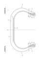
- 1 is a cross-sectional view in the tire width direction of a pneumatic radial tire for a passenger car according to an embodiment of the present invention.
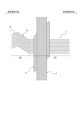
- FIG. 3 is a diagram schematically showing the structures of a carcass, a belt, and a cap layer.
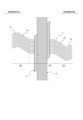
- FIG. 3 is a schematic diagram of another carcass structure.
- FIG. 3 is a diagram schematically showing an improvement in the ground contact shape. It is a figure which shows typically about another example of the structure of a carcass, a belt, and a cap layer.
- FIG. 3 is a diagram for explaining the arrangement of RFIDs.
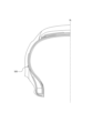
- FIG. 7 is a cross-sectional view in the tire width direction of a modified pneumatic radial tire for a passenger car.
- FIG. 2 is a schematic diagram showing the cross-sectional width SW and outer diameter OD of the tire.
- a pneumatic radial tire for a passenger car (hereinafter also simply referred to as a tire) according to an embodiment of the present invention has a cross-sectional width SW of less than 165 (mm), and a ratio SW of the cross-sectional width SW and the outer diameter OD of the tire. /OD is 0.26 or less, and has a narrow width and large diameter shape. Air resistance can be reduced by making the cross-sectional width SW of the tire narrower than the outer diameter OD of the tire, and by increasing the outer diameter OD of the tire compared to the cross-sectional width SW of the tire.
- the SW/OD is preferably 0.25 or less, more preferably 0.24 or less.
- the above ratio is preferably satisfied when the internal pressure of the tire is 200 kPa or more, more preferably when it is 220 kPa or more, and is satisfied when the tire internal pressure is 280 kPa or more. It is even more preferable. This is because rolling resistance can be reduced.
- the above ratio is preferably satisfied when the internal pressure of the tire is 350 kPa or less. This is because riding comfort can be improved.
- the cross-sectional width SW of the tire is preferably 105 to 145 mm, more preferably 115 to 135 mm.
- the aspect ratio of the tire is more preferably 45 to 70, and more preferably 45 to 65, when the cross-sectional width SW and outer diameter OD of the tire satisfy the above ratio.
- Specific tire sizes are not particularly limited, but examples include 105/50R16, 115/50R17, 125/55R20, 125/60R18, 125/65R19, 135/45R21, 135/55R20, 135/60R17.
- the cross-sectional width SW of the tire is less than 165 mm, and the cross-sectional width SW (mm) and the outer diameter OD (mm) of the tire are determined by the following equation: OD (mm) ⁇ -0.0187 x SW (mm) 2 +9.15 x SW (mm) -380 It has a narrow width and large diameter shape.
- the cross-sectional width SW and outer diameter OD of the tire satisfy the above relational expression, and the ratio SW/OD is preferably 0.26 or less, and preferably 0.25 or less. More preferably, it is 0.24 or less.
- the above relational expression and/or ratio is preferably satisfied when the internal pressure of the tire is 200 kPa or more, more preferably satisfied when it is 220 kPa or more, and more preferably when the internal pressure of the tire is 280 kPa or more. It is more preferable that the condition is satisfied. This is because rolling resistance can be reduced. On the other hand, it is preferable that the above relational expression and/or ratio be satisfied when the internal pressure of the tire is 350 kPa or less. This is because riding comfort can be improved.
- the cross-sectional width SW of the tire is preferably 105 to 145 mm, more preferably 115 to 135 mm.
- the aspect ratio of the tire is more preferably 45 to 70, more preferably 45 to 65, when the cross-sectional width SW and outer diameter OD of the tire satisfy the above relational expression.
- Specific tire sizes are not particularly limited, but examples include 105/50R16, 115/50R17, 125/55R20, 125/60R18, 125/65R19, 135/45R21, 135/55R20, 135/60R17.
- the tire of this embodiment is a pneumatic radial tire for passenger cars. This tire is especially suitable for use as a tire to be mounted on a vehicle for personal mobility.
- FIG. 3 is a cross-sectional view in the tire width direction of a pneumatic radial tire for a passenger car according to an embodiment of the present invention.
- FIG. 3 shows a cross-sectional view of the tire in the width direction in a standard state in which the tire is assembled into a rim, filled with a specified internal pressure, and left unloaded.
- this tire 1 includes a carcass 3 consisting of one or more carcass plies formed by covering a carcass cord with rubber.
- the tire 1 also includes only one inclined belt layer, which is a belt ply made of a rubber-coated belt cord extending at an angle with respect to the tire circumferential direction on the outside in the tire radial direction of the crown portion of the carcass 3. It includes a belt 4 and a tread 5 in this order.
- bead cores 2a are embedded in each of the pair of bead portions 2.
- the cross-sectional shape and material of the bead core 2a are not particularly limited, and may have a configuration commonly used in pneumatic radial tires for passenger cars.
- the bead core 2a may be divided into a plurality of small bead cores.
- the present invention can also be configured without the bead core 2a.
- the illustrated tire 1 has a bead filler 2b having a substantially triangular cross section on the outer side of the bead core 2a in the tire radial direction.
- the cross-sectional shape of the bead filler 2b is not limited to this example, and the material is not particularly limited either.
- the tire can be made lighter by having a configuration that does not include the bead filler 2b.
- the tire 1 can also have a structure including a rim guard.
- additional members such as a rubber layer or a cord layer may be further provided on the bead portion 2 for the purpose of reinforcement or the like.
- Such additional members can be provided at various positions with respect to the carcass 3 and the bead filler 2b.
- the carcass 3 consists of one carcass ply.
- the number of carcass plies is not particularly limited, and may be two or more.
- the carcass 3 includes a first tire width direction portion 301 in which the carcass cords are arranged in a radial arrangement, and a second tire width direction portion 301 in which the carcass cords extend obliquely with respect to the tire circumferential direction. 302, and the second tire width direction portion 302 is located in the outer tire width direction half (in the illustrated example, only a part of the half) when mounted on the vehicle.
- the outer tire width direction half in the illustrated example, only a part of the half
- the carcass 3 includes a carcass main body 3a that straddles the pair of bead parts 2 in a toroidal shape, and a folded part 3b that is folded back from the carcass main body 3a around the bead core 2a. are doing.
- the carcass main body portion 3a extends from the bead portion 2 to the inner side of the belt 4 in the tire radial direction.
- the carcass folded part 3b can be wound around the bead core 2a, or can be sandwiched between a plurality of divided small bead cores.
- the end 3c of the carcass folded portion 3b is located radially outward from the outer end of the bead filler 2b in the tire radial direction, and radially inner from the tire maximum width position. This makes it possible to reduce the weight of the tire while ensuring the rigidity of the sidewall portion.
- the end 3c of the carcass folded portion 3b may be located on the inner side in the tire radial direction from the outer end in the tire radial direction of the bead filler 2b, or may be located on the outer side in the tire radial direction than the tire maximum width position. It may be located.
- the end 3c of the carcass folded portion 3b is located inside the end of the belt 4 (for example, the end of the belt layer 4b) in the tire width direction so as to be located between the carcass main body 2a and the belt 4 in the tire radial direction. It is also possible to have an envelope structure. Furthermore, when the carcass 3 is composed of a plurality of carcass plies, the position (for example, the position in the tire radial direction) of the end 3c of the carcass folded portion 3b can be the same or different between the carcass plies. .
- the number of cords inserted into the carcass 3 is not particularly limited, but may range from 20 to 60 cords/50 mm, for example. Moreover, various structures can be adopted for the carcass line.
- the carcass maximum width position can be moved closer to the bead portion 2 side or closer to the tread 5 side.
- the carcass maximum width position can be set outward in the tire radial direction from the bead baseline in a range of 50% to 90% relative to the tire cross-sectional height.
- the above-mentioned "radial arrangement" is 85 degrees or more with respect to the tire circumferential direction, preferably 90 degrees with respect to the tire circumferential direction.
- the direction of inclination of the belt cord in the second tire width direction portion 302 is opposite between the carcass main body portion 3a and the carcass folded portion 3b, as shown in the figure. As shown in FIG.
- the carcass 3 can be configured to straddle the pair of bead portions 2 in a toroidal manner.
- the carcass 3 includes a first carcass 351 that extends from the bead portion 2 of the outer half in the tire width direction when mounted on the vehicle to the inside of the belt 4 in the tire radial direction;
- a second carcass 352 extending from the bead portion 2 of the inner half in the tire width direction to the inner side of the belt in the tire radial direction may also be configured.
- the second carcass 352 is formed along the first carcass 351 from the outer side to the inner side in the tire radial direction, as shown in the figure. It may have a radially extending portion 352a that extends and terminates at and near the inner side in the tire width direction of the bead portion of the outer half when mounted on a vehicle, or a radially extending portion 352a may be provided for weight reduction. It is also possible to have a configuration that does not include 352a.
- the tire of this embodiment preferably has only one inclined belt layer consisting of a belt ply formed by rubber-covering a belt cord extending at an angle with respect to the tire circumferential direction, and the width of the belt layer in the tire width direction. is preferably 90 to 115% of the ground contact width, particularly preferably 100 to 105% of the ground contact width.
- the "contact width” refers to the distance between the contact edges E in the tire width direction.
- “Ground contact edge” refers to both ends of the tire width direction of the contact surface when the tire is mounted on the rim, filled with the specified internal pressure, and the maximum load is applied.
- the belt cord of the belt layer it is most preferable to use a metal cord, especially a steel cord, but a non-metal, for example, an organic fiber cord (for example, Kevlar (registered trademark)) can also be used.
- Steel cord is mainly composed of steel and can contain various trace amounts of carbon, manganese, silicon, phosphorus, sulfur, copper, chromium, etc.
- the belt cord of the belt layer can be a monofilament cord, a cord made of a plurality of filaments aligned, or a cord made of a plurality of filaments twisted together.
- the inclination angle of the belt cord of the belt layer is preferably 10° or more with respect to the tire circumferential direction. In this embodiment, it is preferable that the inclination angle of the belt cord of the belt layer is a high angle, specifically, 20° or more with respect to the tire circumferential direction, and particularly in the range of 20° to 45° with respect to the tire circumferential direction. .
- the carcass cord and belt cord of the carcass main body 3a in the second tire width direction portion 302 intersect with each other when viewed from the outside in the tire radial direction. extending in the direction.
- the angle of inclination of the carcass cord of the carcass body 3a in the second tire width direction portion 302 with respect to the tire circumferential direction is larger than the inclination angle of the belt cord with respect to the tire circumferential direction.
- the angle of inclination of the carcass cord of the carcass body 3a in the second tire width direction portion 302 with respect to the tire circumferential direction is preferably 70 to 88 degrees, more preferably 76 to 84 degrees.
- the end of the belt 4 is located within the first tire width direction portion 301.
- the width of the cap layer 8 in the tire width direction is smaller than the width of the belt 4 in the tire width direction.
- the position of the inner end in the tire width direction of the second tire width direction portion 302 is spaced from the tire width direction end of the belt 4 outward in the tire width direction by 10 to 40% of the width of the belt 4 in the tire width direction. is preferred.
- the tread rubber constituting the tread 5 consists of one layer.
- the tread rubber constituting the tread 5 may be formed by laminating a plurality of different rubber layers in the tire radial direction.
- the above-mentioned plurality of rubber layers those having different tangent loss, modulus, hardness, glass transition temperature, material, etc. can be used.
- the ratio of the thicknesses of the plurality of rubber layers in the tire radial direction may change in the tire width direction, and only the bottom of the circumferential main groove can be made of a different rubber layer from the surrounding area.
- the tread rubber constituting the tread 5 may be formed of a plurality of different rubber layers in the tire width direction.
- the width ratio of the plurality of rubber layers in the tire width direction may change in the tire radial direction, and may be applied only near the circumferential main groove, only near the ground contact edge, only in the shoulder land area, or only in the center land area. It is also possible to form a rubber layer that is different from the surrounding area only in a limited area.
- the tire 1 of this embodiment has an inner liner 7 on the inner surface 6 of the tire (also simply referred to as the tire inner surface 6).
- the thickness of the inner liner 7 is preferably about 1.5 mm to 2.8 mm. This is because in-vehicle noise of 80 to 100 Hz can be effectively reduced.
- the air permeability coefficient of the rubber composition constituting the inner liner 7 is 1.0 ⁇ 10 ⁇ 14 cc ⁇ cm/(cm 2 ⁇ s ⁇ cmHg) or more, and 6.5 ⁇ 10 ⁇ 10 cc ⁇ cm/(cm 2 ⁇ s ⁇ cmHg) or less.
- this tire further includes one or more cap layers 8 (one layer in the illustrated example) on the outside of the belt 4 in the tire radial direction.
- the cap layer 8 is formed by winding a ribbon-like member made of a rubberized layer of substantially parallel cords in a spiral shape in the tire circumferential direction.
- the width of the cap layer 8 in the tire width direction is smaller than the width of the belt 4 in the tire width direction.
- an organic fiber cord can be used for the cord of the cap layer 8.
- the pneumatic radial tire for passenger cars of this embodiment has a cross-sectional width SW of 165 (mm) among narrow-width, large-diameter tires in which the cross-sectional width SW of the tire and the outer diameter of the tire satisfy the above relational expression.
- the width is less than or equal to According to such a tire, air resistance in particular can be reduced, and rolling resistance can also be reduced, so that the fuel efficiency of the tire can be improved.
- the tire of this embodiment is equipped with a belt consisting of only one inclined belt layer, the tread rubber is It has become difficult to grow.
- the tire of the present embodiment further includes a first tire width direction portion 301 having a radially arranged carcass cord, and a second tire width direction portion 302 having an inclined carcass cord.
- the carcass cord and belt cord of the carcass main body 3a in the second tire width direction portion 302 located in the outer half of the tire width direction extend in directions that intersect with each other when viewed from the outside in the tire radial direction. ing. Therefore, a force acts on the carcass cord of the carcass main body 3a in the second tire width direction portion 302 to restore the radial arrangement, and the force acts in the direction of the force (upward right and downward direction in FIG. 4). It can promote the elongation of tread rubber. As a result, it is possible to alleviate the difficulty in elongating the tread rubber in the direction of inclination of the belt cord, improve the ground contact shape as schematically shown in FIG. 6, and improve maneuverability such as steering stability.
- the inclination angle of the carcass cord of the carcass main body portion 3a in the second tire width direction portion 302 with respect to the tire circumferential direction is larger than the inclination angle of the belt cord with respect to the tire circumferential direction.
- the inclination angle of the carcass cord of the carcass main body 3a in the second tire width direction portion 302 with respect to the tire circumferential direction is 70 to 88 degrees. This is because by setting the angle to 70° or more, both torsional deformation and rigidity can be achieved, while by setting the angle to 88° or less, a sufficient restoring force against torsion can be generated. For the same reason, it is more preferable that the inclination angle is 76 to 84 degrees.
- the position of the inner end in the tire width direction of the second tire width direction portion 302 is from the tire width direction end of the belt 4 (the end of the same tire width direction half part) to the outside in the tire width direction. It is preferable that they be spaced apart by 10 to 40% of the width of. By setting it to 10% or more, it is possible to obtain the effect of correcting the ground contact shape in the entire inner half when installed on a vehicle, while by setting it to 40% or less, it is possible to achieve both torsional deformation and rigidity. It is from.
- the position of the inner end in the tire width direction of the second tire width direction portion 302 is 20 to 30% of the width of the belt 4 in the tire width direction from the tire width direction end to the outer side in the tire width direction. More preferably, they are spaced apart.
- the carcass cord further has a third tire width direction portion 303 that is different from the second tire width direction portion 302 and extends obliquely with respect to the tire circumferential direction.
- the portion 303 is located in the inner half of the tire in the width direction when mounted on a vehicle, and the carcass cord and belt cord of the carcass main body portion 3a in the third tire width direction portion 303, when viewed from the outside in the tire radial direction, Preferably, they extend in directions that intersect with each other. Even in the inner half when mounted on the vehicle, the direction of the force (upward right and downward downward in FIG.
- the ground contact shape can be further improved and the exercise performance can be further improved.
- the pneumatic radial tire for a passenger car is installed on the left wheel of the vehicle, and the belt cord can extend obliquely from the lower left to the upper right when viewed from the outside in the tire radial direction (Fig. 7).
- the belt cord may be attached to the right wheel of the vehicle and extend obliquely from the lower right to the upper left when viewed from the outside in the tire radial direction.
- the carcass 3 can straddle the pair of bead portions 2 in a toroidal manner, or as shown in FIG.
- a first carcass 351 that extends to the inner side of the belt 4 in the tire radial direction, and a second carcass 352 that extends from the bead portion 2 of the inner half in the tire width direction when mounted on the vehicle to the inner side of the belt 4 in the tire radial direction. can have
- FIG. 1 shows that shows that extends to the inner side of the belt 4 in the tire radial direction
- a second carcass 352 that extends from the bead portion 2 of the inner half in the tire width direction when mounted on the vehicle to the inner side of the belt 4 in the tire radial direction.
- a straight line passing through a point on the tread surface in the tire equatorial plane and parallel to the tire width direction is defined as m1
- a straight line passing through the ground contact edge E and parallel to the tire width direction is defined as m2
- Ground contact edge refers to both ends of the tire width direction of the contact surface (the surface in contact with the road surface) when the tire is mounted on the rim, filled with the specified internal pressure, and loaded with the maximum load.
- Thread width refers to the distance in the tire width direction between the ground contact edges when the tire is mounted on a rim, filled with the specified internal pressure, and under no load.
- the tire/rim assembly here is one in which the above-mentioned pneumatic radial tire for a passenger car is assembled into a rim. According to the tire/rim assembly, the same effects as those described for the pneumatic radial tire for passenger cars can be obtained.
- the internal pressure of the tire/rim assembly is preferably 200 kPa or more, more preferably 220 kPa or more, and even more preferably 280 kPa or more. This is because rolling resistance can be further reduced by providing a high internal pressure.
- the internal pressure of the tire/rim assembly is preferably 350 kPa or less. This is because riding comfort can be improved.
- the tire may include an RF tag as a communication device 500.
- the RF tag includes an IC chip and an antenna.
- the RF tag may be placed between a plurality of members of the same type or different types that constitute a tire. By doing so, the RF tag can be easily attached during tire production, and the productivity of tires equipped with the RF tag can be improved.
- the RF tag may be placed between, for example, the bead filler and another member adjacent to the bead filler.
- the RF tag may be embedded in any member that constitutes the tire.
- the load applied to the RF tag can be reduced compared to the case where the RF tag is sandwiched between a plurality of members constituting the tire.
- the durability of the RF tag can be improved.
- the RF tag may be embedded in a rubber member such as tread rubber or side rubber. It is preferable that the RF tag is not placed at a position that is a boundary between members having different rigidities in the periphery length direction, which is a direction along the outer surface of the tire in a cross-sectional view in the tire width direction. By doing so, the RF tag is not placed in a position where distortion is likely to be concentrated due to the difference in rigidity. Therefore, the load applied to the RF tag can be reduced.
- the RF tag is not placed at a position that is a boundary between the end of the carcass and a member (for example, side rubber, etc.) adjacent to the end of the carcass in a cross-sectional view in the tire width direction.
- the number of RF tags is not particularly limited.
- a tire may include only one RF tag, or may include two or more RF tags.
- an RF tag is illustrated as an example of a communication device, but a communication device other than an RF tag may be used.
- the RF tag may be placed, for example, in the tread of a tire. In this way, the RF tag will not be damaged by the side cut of the tire.
- the RF tag may be placed, for example, in the center of the tread in the tire width direction.
- the central portion of the tread is a position where deflection is difficult to concentrate in the tread portion. By doing so, the load applied to the RF tag can be reduced. Thereby, the durability of the RF tag can be improved. Further, it is possible to suppress differences in communication with the RF tag from both outsides of the tire in the tire width direction.
- the RF tag may be arranged, for example, in the tire width direction within a range of 1/2 of the tread width centered on the tire equatorial plane.
- the RF tag may be placed, for example, at the edge of the tread in the width direction of the tire. If the position of the reader communicating with the RF tag is predetermined, the RF tag may be placed, for example, at one tread end close to the reader. In this example, the RF tag may be arranged, for example, in the tire width direction within a range of 1/4 of the tread width, with the tread end being the outer end.
- the RF tag may be placed closer to the inner cavity of the tire than the carcass, which includes one or more carcass plies spanning between the bead portions. By doing so, the RF tag is less likely to be damaged by shocks applied from outside the tire, side cuts, nail penetrations, and other damage.
- the RF tag may be placed in close contact with the tire lumen side surface of the carcass.
- the RF tag may be placed between the carcass and another member located closer to the tire lumen than the carcass. Good too.
- Another member located closer to the inner cavity of the tire than the carcass is, for example, an inner liner that forms the inner surface of the tire.
- the RF tag may be attached to the inner surface of the tire facing the tire bore.
- the RF tag By configuring the RF tag to be attached to the inner surface of the tire, it is easy to attach the RF tag to the tire and to inspect and replace the RF tag. In other words, the ease of attaching and maintaining the RF tag can be improved.
- the RF tag by attaching the RF tag to the inner surface of the tire, compared to a configuration in which the RF tag is buried within the tire, it is possible to prevent the RF tag from becoming the core of tire failure.
- the carcass includes a plurality of carcass plies and there is a position where the plurality of carcass plies are overlapped, the RF tag may be arranged between the overlapped carcass plies.
- the RF tag may be placed, for example, in the tread portion of the tire, on the outside in the tire radial direction from a belt made of only one belt ply.
- the RF tag may be placed on the outside of the belt in the tire radial direction and in close contact with the belt.
- a reinforcing belt layer when a reinforcing belt layer is provided, it may be disposed on the outer side of the reinforcing belt layer in the tire radial direction and in close contact with the reinforcing belt layer.
- the RF tag may be embedded in the tread rubber outside the belt in the tire radial direction.
- the RF tag Since the RF tag is disposed in the tread portion of the tire outside the belt in the tire radial direction, communication with the RF tag from outside the tire in the tire radial direction is less likely to be obstructed by the belt. Therefore, communication with the RF tag from the outside of the tire in the tire radial direction can be improved. Further, the RF tag may be placed, for example, in the tread portion of the tire, inside the belt in the tire radial direction. In this way, since the outside of the RF tag in the tire radial direction is covered by the belt, the RF tag is less likely to be damaged by impact from the tread surface or nail penetration. As an example of this, the RF tag may be placed in the tread portion of a tire between a belt and a carcass located inside the belt in the tire radial direction.
- the RF tag may be placed, for example, at the sidewall or bead of the tire.
- the RF tag may be placed, for example, on one sidewall portion or one side bead portion close to a reader capable of communicating with the RF tag. By doing so, it is possible to improve the communication between the RF tag and the reader.
- the RF tag may be placed between the carcass and the side rubber or between the tread rubber and the side rubber.
- the RF tag may be placed, for example, in the tire radial direction between the tire maximum width position and the tread surface position.
- the RF tag may be placed, for example, on the inner side of the tire in the radial direction from the position where the tire is at its maximum width. By doing so, the RF tag is placed near the highly rigid bead portion. Therefore, the load applied to the RF tag can be reduced. Thereby, the durability of the RF tag can be improved.
- the RF tag may be placed adjacent to the bead core in the tire radial direction or the tire width direction. Distortion is difficult to concentrate near the bead core.
- the load applied to the RF tag can be reduced.
- the durability of the RF tag can be improved.
- the RF tag be arranged at a position radially inside the tire from the maximum tire width position and radially outside the bead core of the bead portion. By doing so, the durability of the RF tag can be improved, and communication between the RF tag and the reader is less likely to be hindered by the bead core, and the communication performance of the RF tag can be improved.
- the RF tag may be placed between the plurality of rubber members that constitute the side rubber. .
- the RF tag may be placed between a bead filler and a member adjacent to the bead filler. By doing so, the RF tag can be placed at a position where distortion is less likely to be concentrated by placing the bead filler. Therefore, the load applied to the RF tag can be reduced. Thereby, the durability of the RF tag can be improved.
- the RF tag may be placed between the bead filler and the carcass. The portion of the carcass where the RF tag is sandwiched together with the bead filler may be located on the outside in the tire width direction with respect to the bead filler, or may be located on the inside in the tire width direction with respect to the bead filler.
- the bead filler may include a portion located adjacent to the side rubber. In such a case, the RF tag may be placed between the bead filler and the side rubber. Additionally, the bead filler may include a portion located adjacent to the rubber chafer. In such a case, the RF tag may be placed between the bead filler and the rubber chafer.
- the RF tag may be placed between the rubber chafer and the side rubber, for example. By doing so, the RF tag can be placed at a position where distortion is less likely to be concentrated by placing the rubber chafer. Therefore, the load applied to the RF tag can be reduced. Thereby, the durability of the RF tag can be improved.
- the RF tag may be placed between the rubber chafer and the carcass, for example. By doing so, it is possible to reduce the load applied to the RF tag due to impact or damage from the rim. Therefore, the durability of the RF tag can be improved.
- the RF tag may be placed between the wire chafer and another member adjacent to the wire chafer on the inside or outside of the wire chafer in the tire width direction.
- Another member adjacent to the wire chafer on the inside or outside in the tire width direction may be, for example, a rubber member such as a rubber chafer.
- another member adjacent to the wire chafer on the inside or outside in the tire width direction may be, for example, a carcass.
- a belt reinforcing layer may further be provided on the radially outer side of the belt.
- the belt reinforcing layer may be formed by continuously winding a cord made of polyethylene terephthalate in a spiral shape in the tire circumferential direction.
- the cord is treated with adhesive by applying a tension of 6.9 ⁇ 10 -2 N/tex or more, and has an elastic modulus of 2.5 mN/dtex ⁇ % at a load of 29.4 N measured at 160°C. It may be more than that.
- the belt reinforcing layer may be disposed to cover the entire belt or may be disposed to cover only both ends of the belt.
- the winding density per unit width of the belt reinforcing layer may vary depending on the position in the width direction. By doing so, road noise and flat spots can be reduced without reducing high-speed durability.
- the present invention is not limited to the above embodiments.
- an example with one cap layer was shown, but in order to reduce the weight of the tire, a structure without a cap layer may also be used.
- SDGs Sustainable Development Goals
- An embodiment of the present invention is described in "No. 7_Energy for everyone and clean", No. It is thought that this technology could contribute to the ⁇ 13_Specific measures against climate change.''
Landscapes
- Engineering & Computer Science (AREA)
- Mechanical Engineering (AREA)
- Tires In General (AREA)
Abstract
Description
(1)一対のビード部と、
カーカスコードをゴム被覆してなる1枚以上のカーカスプライからなるカーカスと、
前記カーカスのクラウン部のタイヤ径方向外側に配置され、タイヤ周方向に対して傾斜して延びるベルトコードをゴム被覆してなるベルトプライからなる1層のみの傾斜ベルト層からなるベルトと、を備えた、乗用車用空気入りラジアルタイヤであって、
前記タイヤの断面幅SWが165(mm)未満であり、
前記タイヤの断面幅SWと外径ODとの比SW/ODは、0.26以下であり、又は、前記タイヤの断面幅SW(mm)及び外径OD(mm)が、関係式、
OD(mm)≧-0.0187×SW(mm)2+9.15×SW(mm)-380(mm)を満たし、
前記カーカスは、前記カーカスコードがラジアル配列である第1のタイヤ幅方向部分と、前記カーカスコードがタイヤ周方向に対して傾斜して延びる第2のタイヤ幅方向部分と、を有し、
前記カーカスは、前記ビード部から前記ベルトのタイヤ径方向内側まで延びる、カーカス本体部を有し、
前記第2のタイヤ幅方向部分は、前記車両装着時外側のタイヤ幅方向半部に位置し、
前記第2のタイヤ幅方向部分における前記カーカス本体部の前記カーカスコードと前記ベルトコードとが、タイヤ径方向外側から見た際に、互いに交差する方向に延びていることを特徴とする、乗用車用空気入りラジアルタイヤ。
ここで、「互いに交差する方向に延びる」とは、タイヤ径方向外側から見た際に交差する場合に限られず、カーカスコードまたはベルトコードを延長した際に交差する場合も含まれる。
また、「規定内圧」とは、上記JATMA等に記載されている、適用サイズ・プライレーティングにおける単輪の最大負荷能力に対応する空気圧(最高空気圧)を指し、上記産業規格に記載のないサイズの場合は、「規定内圧」は、タイヤを装着する車両毎に規定される最大負荷能力に対応する空気圧(最高空気圧)をいうものとする。
また、「最大負荷荷重」とは、上記最大負荷能力に対応する荷重をいうものとする。
本発明の一実施形態の乗用車用空気入りラジアルタイヤ(以下、単にタイヤとも称する)は、タイヤの断面幅SWが165(mm)未満であり、タイヤの断面幅SWと外径ODとの比SW/ODは、0.26以下であり、狭幅・大径の形状をなしている。タイヤの断面幅SWをタイヤの外径ODに比して狭くすることにより、空気抵抗を低減することができ、且つ、タイヤの外径ODをタイヤの断面幅SWに比して大きくすることにより、タイヤの接地面付近でのトレッドゴムの変形を抑制して、転がり抵抗を低減することができ、これらにより、タイヤの燃費性を向上させることができる。上記SW/ODは、0.25以下とすることが好ましく、0.24以下とすることがより好ましい。
上記比は、タイヤの内圧が200kPa以上である場合に満たされるものであることが好ましく、220kPa以上である場合に満たされるものであることがより好ましく、280kPa以上である場合に満たされるものであることがさらに好ましい。転がり抵抗を低減することができるからである。一方で、上記比は、タイヤの内圧が350kPa以下である場合に満たされるものであることが好ましい。乗り心地性を向上させることができるからである。
ここで、タイヤの断面幅SWは、105~145mmとすることが好ましく、115~135mmとすることがより好ましい。
また、タイヤの扁平率は、タイヤの断面幅SW及び外径ODが上記比を満たすとき、45~70とすることがより好ましく、45~65とすることがより好ましい。
具体的なタイヤサイズは、特に限定されるものではないが、一例として、105/50R16、115/50R17、125/55R20、125/60R18、125/65R19、135/45R21、135/55R20、135/60R17、135/60R18、135/60R19、135/65R19、145/45R21、145/55R20、145/60R16、145/60R17、145/60R18、145/60R19、145/65R19、155/45R18、155/45R21、155/55R18、155/55R19、155/55R21、155/60R17、155/65R18、155/70R17、155/70R19のいずれかとすることができる。
OD(mm)≧-0.0187×SW(mm)2+9.15×SW(mm)-380
を満たしており、狭幅・大径の形状をなしている。
上記の関係式を満たすことにより、空気抵抗を低減することができ、且つ、転がり抵抗を低減することができ、これらにより、タイヤの燃費性を向上させることができる。
なお、第3の態様において、タイヤの断面幅SW及び外径ODは、上記の関係式を満たした上で、比SW/ODが0.26以下であることが好ましく、0.25以下であることがより好ましく、0.24以下であることがさらに好ましい。タイヤの燃費性をさらに向上させることができるからである。
上記関係式及び/又は比は、タイヤの内圧が200kPa以上である場合に満たされるものであることが好ましく、220kPa以上である場合に満たされるものであることがより好ましく、280kPa以上である場合に満たされるものであることがさらに好ましい。転がり抵抗を低減することができるからである。一方で、上記関係式及び/又は比は、タイヤの内圧が350kPa以下である場合に満たされるものであることが好ましい。乗り心地性を向上させることができるからである。
ここで、タイヤの断面幅SWは、105~145mmとすることが好ましく、115~135mmとすることがより好ましい。
また、タイヤの扁平率は、タイヤの断面幅SW及び外径ODが上記関係式を満たすとき、45~70とすることがより好ましく、45~65とすることがより好ましい。
具体的なタイヤサイズは、特に限定されるものではないが、一例として、105/50R16、115/50R17、125/55R20、125/60R18、125/65R19、135/45R21、135/55R20、135/60R17、135/60R18、135/60R19、135/65R19、145/45R21、145/55R20、145/60R16、145/60R17、145/60R18、145/60R19、145/65R19、155/45R18、155/45R21、155/55R18、155/55R19、155/55R21、155/60R17、155/65R18、155/70R17、155/70R19のいずれかとすることができる。
本実施形態において、ベルト層のベルトコードとしては、金属コード、特にスチールコードを用いるのが最も好ましいが、非金属、例えば有機繊維コード(例えばケブラー(登録商標)等)を用いることもできる。スチールコードはスチールを主成分とし、炭素、マンガン、ケイ素、リン、硫黄、銅、クロムなど種々の微量含有物を含むことができる。本実施形態において、ベルト層のベルトコードはモノフィラメントコードや、複数のフィラメントを引き揃えたコード、複数のフィラメントを撚り合せたコードを用いることができる。撚り構造も種々のものを採用することができ、断面構造、撚りピッチ、撚り方向、隣接するフィラメント同士の距離も様々なものとすることができる。さらには異なる材質のフィラメントを撚り合せたコードを用いることもでき、断面構造としても特に限定されず、単撚り、層撚り、複撚りなど様々な撚り構造を取ることができる。
本実施形態では、ベルト層のベルトコードの傾斜角度は、タイヤ周方向に対して10°以上とすることが好ましい。本実施形態では、ベルト層のベルトコードの傾斜角度を高角度、具体的にはタイヤ周方向に対して20°以上、特にタイヤ周方向に対して20°~45°の範囲とすることが好ましい。傾斜角度を20°以上とすることにより、タイヤ幅方向に対する剛性を高め、特にコーナリング時の操縦安定性能を向上させることができるからである。また、層間ゴムのせん断変形を減少させて、転がり抵抗を低減することができるからである。
図示例では、ベルト4の端は、第1のタイヤ幅方向部分301内に位置している。図示例では、キャップ層8のタイヤ幅方向の幅は、ベルト4のタイヤ幅方向の幅よりも小さい。
第2のタイヤ幅方向部分302のタイヤ幅方向内側端の位置は、ベルト4のタイヤ幅方向端からタイヤ幅方向外側に、ベルト4のタイヤ幅方向の幅の10~40%離間していることが好ましい。
ここで、本実施形態のタイヤは、1層のみの傾斜ベルト層からなるベルトを備えているため、当該ベルトコードの傾斜方向(図4では右上がり及び左下がりの方向)に対してトレッドゴムが伸びにくくなっている。これに対し、本実施形態のタイヤは、さらに、ラジアル配列のカーカスコードを有する第1のタイヤ幅方向部分301と、傾斜したカーカスコードを有する第2のタイヤ幅方向部分302とを有し、車両装着時外側のタイヤ幅方向半部に位置する第2のタイヤ幅方向部分302におけるカーカス本体部3aのカーカスコードとベルトコードとが、タイヤ径方向外側から見た際に、互いに交差する方向に延びている。このため第2のタイヤ幅方向部分302におけるカーカス本体部3aのカーカスコードには、ラジアル配列に復元しようとする力が働き、当該力の向き(図4では右上がり及び左下がりの方向)へのトレッドゴムの伸びを助長することができる。これにより、ベルトコードの傾斜方向へトレッドゴムが伸びにくくなるのを緩和して、図6に模式的に示すように接地形状を改善し、操縦安定性等の運動性能を向上させることができる。
なお、乗用車用空気入りラジアルタイヤは、車両の左輪に装着され、ベルトコードは、タイヤ径方向外側から見た際に左下から右上に向かって傾斜して延びていることができ(図7)、あるいは、車両の右輪に装着され、ベルトコードは、タイヤ径方向外側から見た際に右下から左上に向かって傾斜して延びていることもできる。
また、図9に示すように、タイヤ赤道面におけるトレッド表面上の点を通りタイヤ幅方向に平行な直線をm1とし、接地端Eを通りタイヤ幅方向に平行な直線をm2として、直線m1と直線m2とのタイヤ径方向の距離を落ち高LCRとし、タイヤのトレッド幅をTWとするとき、比LCR/TWが0.045超であることが好ましい。これにより、クラウン形状が比較的丸いタイヤとなるため、接地形状をショルダー部の接地長がセンター部対比で短い、丸い形状にすることができる。これにより、キャンバ角の変化時に接地形状が細長くなり過ぎないようにして、接地形状の悪化をさらに抑制することができる。「接地端」は、タイヤをリムに装着し、規定内圧を充填し、最大負荷荷重を負荷した際の接地面(路面と接する面)のタイヤ幅方向両端をいう。「トレッド幅」は、タイヤをリムに装着し、規定内圧を充填し、無負荷とした際の、接地端間のタイヤ幅方向距離をいう。
ここでのタイヤ・リム組立体は、上記の乗用車用空気入りラジアルタイヤをリムに組み込んでなるものである。当該タイヤ・リム組立体によれば、上記乗用車用空気入りラジアルタイヤについて説明したのと同様の作用効果を得ることができる。このとき、タイヤ・リム組立体の内圧は、200kPa以上であることが好ましく、220kPa以上であることがより好ましく、280kPa以上であることがさらに好ましい。高内圧とすることで転がり抵抗をより低減することができるからである。一方で、タイヤ・リム組立体の内圧は、350kPa以下であることが好ましい。乗り心地性を向上させることができるからである。
ここでの乗用車用空気入りラジアルタイヤの使用方法は、上記乗用車用空気入りラジアルタイヤを使用する。当該乗用車用空気入りラジアルタイヤの使用方法によれば、上記乗用車用空気入りラジアルタイヤについて説明したのと同様の作用効果を得ることができる。このとき、内圧を200kPa以上として使用することが好ましく、220kPa以上として使用することがより好ましく、280kPa以上として使用することがさらに好ましい。高内圧とすることで転がり抵抗をより低減することができるからである。一方で、内圧を350kPa以下として使用することが好ましい。乗り心地性を向上させることができるからである。
図8に示すように、タイヤは、通信装置500としてのRFタグを備えてよい。RFタグは、ICチップとアンテナとを備える。RFタグは、例えば、タイヤを構成する同種又は異種の複数の部材の間の位置に挟み込まれて配置されてよい。このようにすることで、タイヤ生産時にRFタグを取り付け易く、RFタグを備えるタイヤの生産性を向上させることができる。本例では、RFタグは、例えば、ビードフィラと、ビードフィラに隣接するその他の部材と、の間に挟み込まれて配置されてよい。RFタグは、タイヤを構成するいずれかの部材内に埋設されていてもよい。このようにすることで、タイヤを構成する複数の部材の間の位置に挟み込まれて配置される場合と比較して、RFタグに加わる負荷を低減できる。これにより、RFタグの耐久性を向上させることができる。本例では、RFタグは、例えば、トレッドゴム、サイドゴム等のゴム部材内に埋設されてよい。RFタグは、タイヤ幅方向断面視でのタイヤ外面に沿う方向であるペリフェリ長さ方向において、剛性の異なる部材の境界となる位置に、配置されないことが好ましい。このようにすることで、RFタグは、剛性段差に基づき歪みが集中し易い位置に、配置されない。そのため、RFタグに加わる負荷を低減できる。これにより、RFタグの耐久性を向上させることができる。本例では、RFタグは、例えば、タイヤ幅方向断面視でカーカスの端部と、このカーカスの端部に隣接する部材(例えばサイドゴム等)と、の境界となる位置に配置されないことが好ましい。RFタグの数は特に限定されない。タイヤは、1個のみのRFタグを備えてもよく、2個以上のRFタグを備えてもよい。ここでは、通信装置の一例として、RFタグを例示説明しているが、RFタグとは異なる通信装置であってもよい。
持続可能な社会の実現に向けて、SDGsが提唱されている。本発明の一実施形態は、「No.7_エネルギーをみんなに。そしてクリーンに」、No.13_気候変動に具体的な対策を」などに貢献する技術となり得ると考えられる。
2:ビード部、 2a:ビードコア、 2b:ビードフィラ、 3:カーカス、
301:第1のタイヤ幅方向部分、 302:第2のタイヤ幅方向部分、
303:第3のタイヤ幅方向部分、 4:ベルト、 5:トレッド、
6:タイヤ内面、 7:インナーライナー、
8:キャップ層、 500:通信装置、
CL:タイヤ赤道面
Claims (7)
- 一対のビード部と、
カーカスコードをゴム被覆してなる1枚以上のカーカスプライからなるカーカスと、
前記カーカスのクラウン部のタイヤ径方向外側に配置され、タイヤ周方向に対して傾斜して延びるベルトコードをゴム被覆してなるベルトプライからなる1層のみの傾斜ベルト層からなるベルトと、を備えた、乗用車用空気入りラジアルタイヤであって、
前記タイヤの断面幅SWが165(mm)未満であり、
前記タイヤの断面幅SWと外径ODとの比SW/ODは、0.26以下であり、又は、前記タイヤの断面幅SW(mm)及び外径OD(mm)が、関係式、
OD(mm)≧-0.0187×SW(mm)2+9.15×SW(mm)-380(mm)を満たし、
前記カーカスは、前記カーカスコードがラジアル配列である第1のタイヤ幅方向部分と、前記カーカスコードがタイヤ周方向に対して傾斜して延びる第2のタイヤ幅方向部分と、を有し、
前記カーカスは、前記ビード部から前記ベルトのタイヤ径方向内側まで延びる、カーカス本体部を有し、
前記第2のタイヤ幅方向部分は、前記車両装着時外側のタイヤ幅方向半部に位置し、
前記第2のタイヤ幅方向部分における前記カーカス本体部の前記カーカスコードと前記ベルトコードとが、タイヤ径方向外側から見た際に、互いに交差する方向に延びていることを特徴とする、乗用車用空気入りラジアルタイヤ。 - 前記第2のタイヤ幅方向部分における前記カーカス本体部の前記カーカスコードのタイヤ周方向に対する傾斜角度は、前記ベルトコードのタイヤ周方向に対する傾斜角度より大きい、請求項1に記載の乗用車用空気入りラジアルタイヤ。
- 前記第2のタイヤ幅方向部分における前記カーカス本体部の前記カーカスコードのタイヤ周方向に対する傾斜角度は、70~88°である、請求項1又は2に記載の乗用車用空気入りラジアルタイヤ。
- 前記第2のタイヤ幅方向部分のタイヤ幅方向内側端の位置は、前記ベルトのタイヤ幅方向端からタイヤ幅方向外側に、前記ベルトのタイヤ幅方向の幅の10~40%離間している、請求項1~3のいずれか一項に記載の乗用車用空気入りラジアルタイヤ。
- 前記乗用車用空気入りラジアルタイヤは、車両の左輪に装着され、
前記ベルトコードは、タイヤ径方向外側から見た際に左下から右上に向かって傾斜して延び、
前記カーカスコードがタイヤ周方向に対して傾斜して延びる前記第2のタイヤ幅方向部分とは異なる第3のタイヤ幅方向部分をさらに有し、
前記第3のタイヤ幅方向部分は、前記車両装着時内側のタイヤ幅方向半部に位置し、
前記第3のタイヤ幅方向部分における前記カーカス本体部の前記カーカスコードと前記ベルトコードとが、タイヤ径方向外側から見た際に、互いに交差する方向に延びている、請求項1~4のいずれか一項に記載の乗用車用空気入りラジアルタイヤ。 - 前記カーカスは、一対のビード部間をトロイダル状に跨る、請求項1~5のいずれか一項に記載の乗用車用空気入りラジアルタイヤ。
- 前記カーカスは、車両装着時外側のタイヤ幅方向半部のビード部から前記ベルトのタイヤ径方向内側まで延びる、第1のカーカスと、車両装着時内側のタイヤ幅方向半部のビード部から前記ベルトのタイヤ径方向内側まで延びる、第2のカーカスと、を有する、請求項1~5のいずれか一項に記載の乗用車用空気入りラジアルタイヤ。
Priority Applications (3)
| Application Number | Priority Date | Filing Date | Title |
|---|---|---|---|
| EP23852208.0A EP4570516A4 (en) | 2022-08-08 | 2023-05-24 | RADIAL PNEUMATIC TIRE FOR PASSENGER VEHICLES |
| US19/099,777 US20260021680A1 (en) | 2022-08-08 | 2023-05-24 | Pneumatic radial tire for passenger vehicle |
| CN202380052483.7A CN119497673A (zh) | 2022-08-08 | 2023-05-24 | 乘用车用充气子午线轮胎 |
Applications Claiming Priority (2)
| Application Number | Priority Date | Filing Date | Title |
|---|---|---|---|
| JP2022126658A JP2024023084A (ja) | 2022-08-08 | 2022-08-08 | 乗用車用空気入りラジアルタイヤ |
| JP2022-126658 | 2022-08-08 |
Publications (1)
| Publication Number | Publication Date |
|---|---|
| WO2024034224A1 true WO2024034224A1 (ja) | 2024-02-15 |
Family
ID=89851539
Family Applications (1)
| Application Number | Title | Priority Date | Filing Date |
|---|---|---|---|
| PCT/JP2023/019384 Ceased WO2024034224A1 (ja) | 2022-08-08 | 2023-05-24 | 乗用車用空気入りラジアルタイヤ |
Country Status (5)
| Country | Link |
|---|---|
| US (1) | US20260021680A1 (ja) |
| EP (1) | EP4570516A4 (ja) |
| JP (1) | JP2024023084A (ja) |
| CN (1) | CN119497673A (ja) |
| WO (1) | WO2024034224A1 (ja) |
Families Citing this family (1)
| Publication number | Priority date | Publication date | Assignee | Title |
|---|---|---|---|---|
| WO2024190534A1 (ja) | 2023-03-10 | 2024-09-19 | 三ツ星ベルト株式会社 | 歯付ベルトおよびその製造方法 |
Citations (7)
| Publication number | Priority date | Publication date | Assignee | Title |
|---|---|---|---|---|
| DE2164366A1 (de) * | 1971-12-23 | 1973-06-28 | Continental Gummi Werke Ag | Fahrzeugluftreifen |
| JP2002127712A (ja) * | 2000-10-27 | 2002-05-08 | Sumitomo Rubber Ind Ltd | 空気入りタイヤ |
| JP2006256522A (ja) * | 2005-03-17 | 2006-09-28 | Toyo Tire & Rubber Co Ltd | 空気入りタイヤ |
| JP2009227229A (ja) * | 2008-03-25 | 2009-10-08 | Toyo Tire & Rubber Co Ltd | 空気入りラジアルタイヤ |
| WO2011135774A1 (ja) | 2010-04-30 | 2011-11-03 | 株式会社ブリヂストン | 乗用車用空気入りラジアルタイヤ |
| WO2012176476A1 (ja) * | 2011-06-22 | 2012-12-27 | 株式会社ブリヂストン | 乗用車用空気入りラジアルタイヤ、該タイヤの使用方法及び、該タイヤを備えるタイヤ・リム組立体 |
| WO2017195891A1 (ja) * | 2016-05-12 | 2017-11-16 | 横浜ゴム株式会社 | 空気入りタイヤ |
Family Cites Families (7)
| Publication number | Priority date | Publication date | Assignee | Title |
|---|---|---|---|---|
| JPS5510402A (en) * | 1978-07-04 | 1980-01-24 | Tokuyama Soda Kk | Plaster cement composition |
| JP2001039110A (ja) * | 1999-07-30 | 2001-02-13 | Bridgestone Corp | 空気入りラジアルタイヤ |
| JP4650917B2 (ja) * | 2001-03-15 | 2011-03-16 | 東洋ゴム工業株式会社 | 空気入りタイヤ |
| JP4500075B2 (ja) * | 2004-03-22 | 2010-07-14 | 住友ゴム工業株式会社 | 空気入りタイヤ |
| CN105163955B (zh) * | 2013-04-30 | 2017-10-27 | 株式会社普利司通 | 乘用车用充气子午线轮胎 |
| JP2020093677A (ja) * | 2018-12-13 | 2020-06-18 | 株式会社ブリヂストン | 乗用車用空気入りラジアルタイヤ |
| FR3106528B1 (fr) * | 2020-01-29 | 2021-12-24 | Michelin & Cie | Pneumatique pour motocyclette |
-
2022
- 2022-08-08 JP JP2022126658A patent/JP2024023084A/ja active Pending
-
2023
- 2023-05-24 CN CN202380052483.7A patent/CN119497673A/zh active Pending
- 2023-05-24 WO PCT/JP2023/019384 patent/WO2024034224A1/ja not_active Ceased
- 2023-05-24 US US19/099,777 patent/US20260021680A1/en active Pending
- 2023-05-24 EP EP23852208.0A patent/EP4570516A4/en active Pending
Patent Citations (7)
| Publication number | Priority date | Publication date | Assignee | Title |
|---|---|---|---|---|
| DE2164366A1 (de) * | 1971-12-23 | 1973-06-28 | Continental Gummi Werke Ag | Fahrzeugluftreifen |
| JP2002127712A (ja) * | 2000-10-27 | 2002-05-08 | Sumitomo Rubber Ind Ltd | 空気入りタイヤ |
| JP2006256522A (ja) * | 2005-03-17 | 2006-09-28 | Toyo Tire & Rubber Co Ltd | 空気入りタイヤ |
| JP2009227229A (ja) * | 2008-03-25 | 2009-10-08 | Toyo Tire & Rubber Co Ltd | 空気入りラジアルタイヤ |
| WO2011135774A1 (ja) | 2010-04-30 | 2011-11-03 | 株式会社ブリヂストン | 乗用車用空気入りラジアルタイヤ |
| WO2012176476A1 (ja) * | 2011-06-22 | 2012-12-27 | 株式会社ブリヂストン | 乗用車用空気入りラジアルタイヤ、該タイヤの使用方法及び、該タイヤを備えるタイヤ・リム組立体 |
| WO2017195891A1 (ja) * | 2016-05-12 | 2017-11-16 | 横浜ゴム株式会社 | 空気入りタイヤ |
Non-Patent Citations (1)
| Title |
|---|
| See also references of EP4570516A4 |
Also Published As
| Publication number | Publication date |
|---|---|
| US20260021680A1 (en) | 2026-01-22 |
| EP4570516A1 (en) | 2025-06-18 |
| EP4570516A4 (en) | 2025-11-19 |
| CN119497673A (zh) | 2025-02-21 |
| JP2024023084A (ja) | 2024-02-21 |
Similar Documents
| Publication | Publication Date | Title |
|---|---|---|
| EP2332744A2 (en) | Pneumatic tire | |
| JP6442228B2 (ja) | 乗用車用空気入りタイヤ | |
| CN112440623A (zh) | 充气轮胎 | |
| JP4377934B2 (ja) | 空気入りタイヤ | |
| WO2024034224A1 (ja) | 乗用車用空気入りラジアルタイヤ | |
| JP2012116246A (ja) | 空気入りタイヤ | |
| JP7818488B2 (ja) | 乗用車用空気入りラジアルタイヤ | |
| JP2007161027A (ja) | 空気入りタイヤ | |
| US20260034836A1 (en) | Pneumatic radial tire for passenger vehicle | |
| WO2024034225A1 (ja) | 乗用車用空気入りラジアルタイヤ | |
| JP7776323B2 (ja) | 乗用車用空気入りラジアルタイヤ | |
| JP7759785B2 (ja) | 乗用車用空気入りラジアルタイヤ | |
| JP7657702B2 (ja) | 乗用車用空気入りラジアルタイヤ | |
| JP7731277B2 (ja) | 乗用車用空気入りラジアルタイヤ | |
| JP7731278B2 (ja) | 乗用車用空気入りラジアルタイヤ | |
| JP7732879B2 (ja) | 乗用車用空気入りラジアルタイヤ | |
| JP7755475B2 (ja) | 乗用車用空気入りラジアルタイヤ |
Legal Events
| Date | Code | Title | Description |
|---|---|---|---|
| 121 | Ep: the epo has been informed by wipo that ep was designated in this application |
Ref document number: 23852208 Country of ref document: EP Kind code of ref document: A1 |
|
| WWE | Wipo information: entry into national phase |
Ref document number: 202380052483.7 Country of ref document: CN |
|
| WWP | Wipo information: published in national office |
Ref document number: 202380052483.7 Country of ref document: CN |
|
| WWE | Wipo information: entry into national phase |
Ref document number: 2023852208 Country of ref document: EP |
|
| NENP | Non-entry into the national phase |
Ref country code: DE |
|
| ENP | Entry into the national phase |
Ref document number: 2023852208 Country of ref document: EP Effective date: 20250310 |
|
| WWP | Wipo information: published in national office |
Ref document number: 2023852208 Country of ref document: EP |