WO2024034449A1 - 情報処理装置、及び情報処理方法 - Google Patents
情報処理装置、及び情報処理方法 Download PDFInfo
- Publication number
- WO2024034449A1 WO2024034449A1 PCT/JP2023/027953 JP2023027953W WO2024034449A1 WO 2024034449 A1 WO2024034449 A1 WO 2024034449A1 JP 2023027953 W JP2023027953 W JP 2023027953W WO 2024034449 A1 WO2024034449 A1 WO 2024034449A1
- Authority
- WO
- WIPO (PCT)
- Prior art keywords
- depth data
- viewpoints
- depth
- labeling
- information processing
- Prior art date
- Legal status (The legal status is an assumption and is not a legal conclusion. Google has not performed a legal analysis and makes no representation as to the accuracy of the status listed.)
- Ceased
Links
Images


Classifications
-
- G—PHYSICS
- G06—COMPUTING OR CALCULATING; COUNTING
- G06T—IMAGE DATA PROCESSING OR GENERATION, IN GENERAL
- G06T17/00—Three-dimensional [3D] modelling for computer graphics
-
- G—PHYSICS
- G06—COMPUTING OR CALCULATING; COUNTING
- G06T—IMAGE DATA PROCESSING OR GENERATION, IN GENERAL
- G06T7/00—Image analysis
- G06T7/50—Depth or shape recovery
- G06T7/55—Depth or shape recovery from multiple images
-
- G—PHYSICS
- G06—COMPUTING OR CALCULATING; COUNTING
- G06T—IMAGE DATA PROCESSING OR GENERATION, IN GENERAL
- G06T2207/00—Indexing scheme for image analysis or image enhancement
- G06T2207/20—Special algorithmic details
- G06T2207/20084—Artificial neural networks [ANN]
Definitions
- the present invention relates to an information processing device and an information processing method.
- Patent Document 1 there has been a technique for generating a three-dimensional model from a two-dimensional image (a large number of two-dimensional images) including a subject (see, for example, Patent Document 1 and Non-Patent Document 1).
- Patent Document 1 has not been able to sufficiently meet the demands regarding the accuracy and generation speed of three-dimensional model generation.
- the present invention has been made in view of this situation, and aims to improve the convenience in generating a three-dimensional model using two-dimensional images.
- an information processing device includes: Depth data acquisition means for acquiring depth data indicating the depth from a predetermined viewpoint to a feature point of the object for each of N (N is an integer value of 2 or more) viewpoints; object surface labeling means for generating labeling data indicating a result of labeling the surface of the object based on the N depth data; Image data acquisition means for acquiring M image data obtained as a result of imaging the object from viewpoints synchronized with each of M viewpoints (M is an integer value equal to or less than N) among the N viewpoints; Model generation means for generating a three-dimensional model of the object based on the M image data and the labeling data; Equipped with.
- An information processing method is an information processing method corresponding to the above-described information processing apparatus according to one embodiment of the present invention.
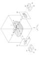
- FIG. 1 is a diagram showing an overview of this service that can be realized by a model generation device according to an embodiment of an information processing device of the present invention.
- 2 is a diagram illustrating an example of a method of arranging cameras and lidar for acquiring depth data and image data in the service shown in FIG. 1.
- FIG. FIG. 2 is a block diagram showing an example of the hardware configuration of a model generation device applied to the present service described using FIG. 1, that is, a model generation device of an embodiment of the information processing device of the present invention.
- 4 is a functional block diagram showing an example of the functional configuration of the model generation device of FIG. 3.
- FIG. 5 is a diagram showing an example of blocks for three-dimensional model generation in the model generation device having the functional configuration of FIG. 4.
- the embodiment of the information processing device of the present invention is based on the premise of using an algorithm that generates a three-dimensional model based on a two-dimensional image. That is, the service to which the embodiment of the information processing device of the present invention is applied (hereinafter referred to as "this service") acquires a two-dimensional image of a predetermined object existing in the real world, and It generates a three-dimensional model from an image.
- this service acquires a two-dimensional image of a predetermined object existing in the real world, and It generates a three-dimensional model from an image.
- Patent Document 1 the conventional basic technology described in the above-mentioned Patent Document 1 and the like will be explained.
- image points are extracted from each of multiple images of an object taken from multiple viewpoints, and the feature points of each of the multiple images are correlated to create a point cloud in three-dimensional space.
- An algorithm was adopted that generates a three-dimensional image by adding a point group from points other than the feature points.
- Such an algorithm is an algorithm that performs linear interpolation, in which distances from several viewpoints to feature points are reconstructed as a point group in a three-dimensional space based on triangulation technology. Therefore, the conventional technology described in Patent Document 1 and the like has a problem in that the reproducibility of angles between images is extremely low.
- NeRF Neral Radiance Fields
- Algorithm a method that can perform nonlinear interpolation between multiple viewpoints using a neural network. More specifically, in NeRF, first a coarse grid is generated and a learning process is performed, and then a final 3D model is output as the learning result by learning to generate a dense grid. can do.
- learning data is encoded using a hash function during learning processing, so that it can be used in learning processing in conventional NeRF, for example.
- a process that used to take about three days can be completed in just a few seconds.
- the present invention realizes faster learning processing for generating a three-dimensional model.
- FIG. 1 will be used to outline the flow of three-dimensional model generation for this service.
- an object T for which a three-dimensional model is to be generated in this service is illustrated in a three-dimensional space.
- N viewpoints N is an integer value of 2 or more
- M viewpoints M is an integer value of 2 or more
- a three-dimensional model of the object T is generated from the following integer values) using the image data of the captured image captured by the camera.
- a camera C1 is installed at the viewpoint P1 in FIG. 1, image data is acquired from the camera C1, and then a lidar D1 is installed at the viewpoint P1 and depth data is acquired from the lidar D1.
- a lidar D1 is installed at the viewpoint P1 and depth data is acquired from the lidar D1.
- FIG. 2 is a diagram showing an example of a method of arranging cameras and lidar for acquiring depth data and image data in the service shown in FIG. 1.
- the camera C1 and the rider D1 are fixed to each other in advance using a predetermined jig, and the camera C1 is placed at the viewpoint P1.
- depth data is acquired from the lidar D1.
- depth data and image data from the same viewpoint are acquired.
- both the image data and the depth data are linked to the same viewpoint, so it can be said that the image data and the depth data are synchronized with each other. Note that this service will be described below assuming that this second method is adopted.
- a captured image G1 obtained as a result of capturing an image of the target object T using the camera C1 from a viewpoint P1 in the positive direction of the axis X of the target object T is captured.
- depth data from a viewpoint synchronized with viewpoint P1 is simultaneously acquired using lidar D1.
- the depth data is calibrated accordingly.
- the captured image G1 includes information on the shape and color of the object T seen from the viewpoint P1.
- a captured image G2 obtained as a result of capturing an image of the target object T using the camera C2 from a viewpoint P2 in the positive direction of the axis Y of the target object T is captured.
- depth data from a viewpoint synchronized with viewpoint P2 is simultaneously obtained using lidar D2.
- the depth data is calibrated accordingly.
- the captured image G2 includes information on the shape and color of the object T seen from the viewpoint P2.
- cameras C1 and C2 and lidar D1 and D2 are used at viewpoints P1 and P2, respectively, but camera C1 and lidar D1 are moved from viewpoint P1 to viewpoint P2, and the camera is By using it as C2 and lidar D2, image data and depth data may be acquired sequentially.
- image data and depth data may be acquired sequentially.
- cameras and lidar at multiple locations they are collectively referred to as “camera C” and “lidar D,” respectively.
- the image captured by camera C is referred to as "captured image G.”
- this service As described above, the image data of the captured image G acquired by the camera C from a plurality of viewpoints P and the depth data acquired by the lidar D are used to Generate a dimensional model. As a result, this service can generate a three-dimensional model faster.
- an arrow passing through a predetermined pixel PX1 of the captured image G1 from the viewpoint P1 is illustrated by a two-dot chain line.
- a white circle and a black circle are illustrated at the points on the arrow indicated by the two-dot chain line.
- a point on the arrow indicated by a white circle indicates that the point is before contacting the object T when viewed from the viewpoint P1.
- a point on the arrow indicated by a black circle indicates that the point has come into contact with the object T when viewed from the viewpoint P1.
- the object T moves along the arrow indicated by the two-dot chain line from the viewpoint P1
- the object T will move forward while passing the point on the arrow indicated by the white circle from the viewpoint P1. It doesn't collide with anything because it doesn't exist. Then, it collides with the object T between the point on the arrow indicated by the white circle and the point on the arrow indicated by the black circle.
- the color of the point that collided with the object T is recorded as the color of a predetermined pixel PX1 of the captured image G1.
- the object T is opaque, points after the first black circle point are not captured in the captured image G1. In this way, the color of the predetermined pixel PX1 of the captured image G1 is the color of the object T at the point where it collided with the object T on the arrow passing through the predetermined pixel PX1 from the viewpoint P1.
- this service improves the speed of 3D model generation by limiting the area to be considered in 3D model generation.
- FIG. 3 is a block diagram showing an example of the hardware configuration of a model generation device applied to the service described using FIG. 1, that is, a model generation device of an embodiment of the information processing device of the present invention.
- the model generation device 1 includes a CPU 11, a GPU 12, a ROM 13, a RAM 14, a bus 15, an input/output interface 16, an output section 17, an input section 18, a storage section 19, a communication section 20, and a drive 21. It is equipped with.
- the CPU 11 and the GPU 12 execute various processes according to programs recorded in the ROM 13 or programs loaded into the RAM 14 from the storage unit 19.
- the GPU 12 has a compute unit that executes software processing and an RT core that executes hardware processing.
- the RT core uses hardware to perform ray tracing on a predetermined three-dimensional space including an object.
- the RAM 14 also appropriately stores data necessary for the CPU 11 and the GPU 12 to execute various processes.
- the CPU 11, GPU 12, ROM 13, and RAM 14 are interconnected via a bus 15.
- An input/output interface 16 is also connected to this bus 15.
- An output section 17 , an input section 18 , a storage section 19 , a communication section 20 , and a drive 21 are connected to the input/output interface 16 .
- the output unit 17 is composed of a display, a speaker, etc., and outputs various information as images and sounds.
- the input unit 18 includes a keyboard, a mouse, etc., and inputs various information.
- the storage unit 19 is composed of a hard disk, a DRAM (Dynamic Random Access Memory), etc., and stores various data.
- the communication unit 20 communicates with other devices via a network including the Internet.
- a removable medium 31 made of a magnetic disk, an optical disk, a magneto-optical disk, a semiconductor memory, or the like is appropriately installed in the drive 21 .
- the program read from the removable medium 31 by the drive 21 is installed in the storage unit 19 as necessary. Further, the removable medium 31 can also store various data stored in the storage section 19 in the same manner as the storage section 19.
- FIG. 4 is a functional block diagram showing an example of the functional configuration of the model generation device shown in FIG. 3.
- the CPU 11 of the model generation device 1 includes an actual depth data acquisition section 51, a depth data estimation section 52, a surface labeling section 53, an image data acquisition section 54, and a three-dimensional model generation section 55.
- display control section 56 function.
- a depth model 80, labeling data 81, and a three-dimensional model 82 are stored in one area of the storage unit 19.
- the depth data acquisition unit acquires depth data from the N predetermined viewpoints to the object T.
- the depth data includes information on the depth from a predetermined viewpoint to a feature point of the object T.
- the depth data acquisition section includes an actual depth data acquisition section 51 and a depth data estimation section 52.
- the actual depth data acquisition unit 51 acquires M actual depth data obtained as a result of measurement from each of M viewpoints in the real world. That is, the actual depth data acquisition unit 51 acquires M actual depth data obtained as a result of measurement using lidar D from each of M viewpoints in the real world.
- the depth data estimation unit 52 estimates N depth data based on the M actual depth data acquired by the actual depth data acquisition unit 51, and acquires the estimated N depth data.
- the depth data estimating unit 52 performs a learning process based on the M actual depth data acquired by the actual depth data acquisition unit 51 using an algorithm using a neural network.
- a dimensional depth model 80 is generated or updated.
- the three-dimensional depth model 80 of the object T is a model that can infer depth data from a predetermined viewpoint.
- the depth model 80 is stored and managed in one area of the storage unit 19.
- the surface labeling unit 53 generates labeling data 81 indicating the result of labeling the surface of the object T based on the N depth data acquired by the depth data acquisition unit. Labeling refers to recording the position of the surface of the object T in a three-dimensional space at a position in a three-dimensional virtual space for generating a three-dimensional model. An example of labeling will be described later using Figure ⁇ .
- the labeling data 81 is stored and managed in one area of the storage unit 19.
- the image data acquisition unit 54 acquires M captured images G obtained as a result of capturing the object T from a viewpoint P that is synchronized with each of M (M is an integer value equal to or less than N) viewpoints among the N viewpoints. Get data.
- the three-dimensional model generation unit 55 generates a three-dimensional model 82 for the object T based on the image data of M and the labeling data 81 acquired by the image data acquisition unit 54.
- the three-dimensional model 82 is stored and managed in one area of the storage unit 19.
- the three-dimensional model generation section 55 includes a block skip determination section 551 and a color learning section 552.
- the block skip determining unit 551 uses a line of sight (indicated by a two-dot chain line in FIG. It is determined whether or not the surface of the object T exists for the block through which the arrow) passes. If the block skip determining unit 551 determines that the surface of the object T does not exist in that block, that block is assumed to not contribute to the color of the predetermined pixel of the captured image G. Conversely, if the block skip determining unit 551 determines that the surface of the target object T exists in that block, it is assumed that that block may contribute to the color of that predetermined pixel of the captured image G. . Then, based on the determination by the block skip determination unit 551, learning data is generated for the block determined to contribute to the color of the predetermined pixel. Note that examples of blocks skipped by the block skip determination unit 551 will be described later using FIG. 5.
- the color learning unit 552 generates or updates the three-dimensional model 82 by performing learning to assign colors to the three-dimensional model 82 using the learning data generated based on the determination result of the block skip determining unit 551. do.
- the learning data used in the color learning unit 552 is data in which learning processing is not (substantially) performed for blocks that do not contribute to the color of a predetermined pixel of the captured image G, as described above. . This reduces the time required for learning processing in the color learning section 552.
- the display control unit 56 performs control to display a three-dimensional model 82 of the object T on the user terminal 2 by performing a drawing process on the vicinity of the object T based on the depth model 80 . This makes image generation and display faster by omitting drawing of areas that do not affect the color of the three-dimensional model 82 when viewing the three-dimensional model 82 from each direction. .
- the display control unit 56 can perform control to display an image drawn as the network representation generated in the three-dimensional model 82 for the target object T.
- the three-dimensional model 82 of the object T represented by the network refers to the form of representation of a function created by a neural network.
- the representation form of a function created by a neural network is also called, for example, an implicit function representation.
- adopting the network representation has the advantage of increasing the transfer speed when transmitting and receiving data of the three-dimensional model 82 (for example, when downloading via the Internet). That is, the display control unit 56 can perform control to display the three-dimensional model 82 of the target object T as it is in the network representation without re-rendering it.
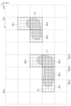
- FIG. 5 is a diagram showing an example of blocks for three-dimensional model generation in the model generation device having the functional configuration of FIG. 4.
- the rough grid shown in FIG. 5 indicates the boundaries of blocks obtained by dividing the virtual three-dimensional space in which the object T shown in FIG. 1 is arranged into a grid. Further, the fine grid shown in FIG. 5 indicates a boundary divided by a finer grid compared to the blocks.
- a slice SLk shown in FIG. 5 is an arrangement of blocks LB and voxels VC at a certain axis Z coordinate.
- each region obtained as a result of dividing the slice SLk into a predetermined first unit is a voxel VC.
- this voxel VC corresponds to the resolution of the three-dimensional model 82 that is finally generated, the processing becomes inefficient if the three-dimensional model generation process is performed using the voxel VC as a unit.
- each region obtained as a result of dividing the slice SLk into a second unit larger than the first unit, in other words, a region composed of a group of n voxels, is introduced as blocks BL1 to BL7 and BLK.
- n is 8 in total, including 4 in the axis X direction, 4 in the axis Y direction, and 1 in the axis Z direction.
- voxel VC when there is no need to distinguish between a plurality of voxels individually, they will be referred to as "voxel VC”. Similarly, when there is no need to distinguish individual blocks BL1 to BL7, etc., they are called “blocks BL”.
- the area of the block BL indicated by the thick line in FIG. 5 is an area that can include objects of the two parts T1 and T2 of the target object T. That is, in the slice SLk, a block BL that may include the surface of the object T and a block BLK that is an empty space are distinguished.
- the former block BL is reflected in the pixel value (color) of a predetermined pixel of the captured image G, while the latter block BLK is not reflected. Therefore, hereinafter, the former block BL will be referred to as a "processing block BL", and the latter block BLK will be referred to as a "non-processing block BLK".
- processing blocks BL are illustrated with thick lines, and “non-processing blocks BLK” are illustrated with broken lines. Note that in FIGS. 3 to 5, only the "processing block BL" is illustrated. Specifically, for example, in the example of FIG. 2, the slice SLk has a region that can include each of the two portions T1 and T2 of the object T.
- processing blocks BL1 to BL4 are illustrated as regions that can include portion T1 of object T.
- processing blocks BL5 to BL7 are illustrated as regions that can include the portion T2 of the object T.
- the surface labeling unit 53 described in FIG. 4 performs labeling by determining the blocks BL that can include the surfaces of the portions T1 and T2 of the target object T in this way.
- a block surrounded by a thick frame indicates that the block is labeled as having the surface of the object T.
- the three-dimensional model generation unit 55 learns (models) the color information about the processing block BL, and generates the color information about the non-processing block BLK as learning (modeling) data so that the learning process is not performed. Then, the three-dimensional model 82 is generated or updated. This speeds up the process of generating or updating the three-dimensional model 82. That is, for example, in a captured image G (for example, captured image G2 in FIG. 1) captured from the positive direction of the axis Y of the portion T1 of the object T, learning data is generated in which learning of non-processing blocks BLK1 to BLK3 is not performed. It will be done.
- the number N of viewpoints P from which depth data is acquired and the number M of viewpoints P from which image data is acquired are described as being the same, but the present invention is not particularly limited to this. That is, the number N of viewpoints P from which depth data is acquired and the number M of viewpoints P from which image data is acquired may be different.
- the depth model 80 is first generated from the depth data of N, and the depth data at the viewpoint P of M, which is different from the viewpoint P of N, is calculated from the depth model 80 using the depth model 80. can do.
- the depth data may be directly observed by a sensor such as the lidar D, or may be estimated from other data. That is, for example, the depth data acquisition unit acquires actual depth data, generates or updates the depth model 80, and uses a previously prepared depth instead of acquiring the depth data at the viewpoint P of M corresponding to the image data. Depth data at the viewpoint P of M corresponding to the image data may be obtained from the model 80.
- the camera C1 and the lidar D1 are fixed to each other in advance using a predetermined jig, and the relative position and direction of measurement (line of sight) between the camera C1 and the lidar D1 are determined by the predetermined jig.
- depth data and image data from the same viewpoint are acquired by calibrating the images
- the present invention is not particularly limited to this. That is, various calibration methods may be employed. Specifically, for example, after acquiring and recording the positional information of a viewpoint P photographed by a camera C using a technology such as GPS (Global Positioning System), depth data is acquired from the same viewpoint by a lidar D using that positional information. may be obtained. Note that it goes without saying that the order in which data is acquired by camera C or lidar D may be acquired first.
- the depth model 80 may be generated using a method of estimating depth from image data such as structure from motion.
- the functional block diagram shown in FIG. 4 is merely an example and is not particularly limited. In other words, it is sufficient that the information processing system is equipped with a function and a database that can execute the above-mentioned series of processes as a whole, and what kind of functional blocks are used to realize this function is particularly explained in the example shown in FIG. Not limited. Further, the locations of the functional blocks and the database are not limited to those shown in FIG. 4, and may be arbitrary.
- one functional block may be configured by a single piece of hardware, a single piece of software, or a combination thereof.
- a program constituting the software is installed on a computer or the like from a network or a recording medium.
- the computer may be a computer built into dedicated hardware. Further, the computer may be a computer that can execute various functions by installing various programs, such as a server, a general-purpose smartphone, or a personal computer.
- Recording media containing such programs not only consist of removable media (not shown) that is distributed separately from the main body of the device in order to provide the program to the user, but also are provided to the user in a state that is pre-installed in the main body of the device. Consists of provided recording media, etc.
- the step of writing a program to be recorded on a recording medium is not only a process that is performed chronologically in accordance with the order, but also a process that is not necessarily performed chronologically but in parallel or individually. It also includes the processing to be executed.
- the term system refers to an overall device composed of a plurality of devices, a plurality of means, and the like.
- the information processing system to which the present invention is applied only needs to have the following configuration, and can take various embodiments. That is, the information processing device to which the present invention is applied (for example, the model generation device 1 in FIG. 4), N (N is 2 a depth data acquisition means (for example, the depth data acquisition unit in FIG. 4) that acquires for each viewpoint (the above integer value); An object surface labeling means (for example, the surface labeling unit in FIG. 4) that generates labeling data (for example, the labeled block BL in FIG. 5) indicating the result of labeling the surface of the object based on the N depth data. 53) and M images obtained as a result of imaging the object from viewpoints (for example, viewpoints P1 and P2 in FIG.
- Image data acquisition means for example, the image data acquisition unit 54 in FIG. 4) that acquires data (for example, image data G1, G2 in FIG. 1); a model generation unit (for example, the three-dimensional model generation unit 55 in FIG. 4) that generates a three-dimensional model of the object based on the M image data and the labeling data; It is sufficient to have the following. As a result, modeling in a space where the object T does not exist (learning process regarding colors, etc.) is omitted, and high-speed modeling is realized.
- the depth data acquisition means includes: An actual depth data acquisition means (for example, the actual depth data acquisition unit 51 in FIG. 4) that acquires M actual depth data obtained as a result of measurements from each of M viewpoints in the real world; Depth data estimating means (for example, the depth data estimating unit 52 in FIG. 4) that estimates N depth data based on the M actual depth data and obtains the estimated N depth data. .
- An actual depth data acquisition means for example, the actual depth data acquisition unit 51 in FIG. 4
- Depth data estimating means for example, the depth data estimating unit 52 in FIG. 4
- the depth data acquisition means includes: The depth data synchronized with each of the M viewpoints among the N viewpoints may be calibrated to have the same viewpoint as the M image data.
- a display control means (for example, the display control unit 56 in FIG. 4) that executes control to draw only the vicinity of the object and display the three-dimensional model of the object based on the depth data; It is possible to further include the following.
- the rendering process by omitting the rendering of the area where the target object does not exist, the calculation load can be reduced and the three-dimensional model can be drawn at high speed.
- the display control means includes: Control can be executed to display an image drawn as is in the network representation generated in the three-dimensional model of the target object. As a result, the three-dimensional model is drawn in its network representation.
- SYMBOLS 1 Model generation device, 2... User terminal, 11... CPU, 19... Storage unit, 21... Drive, 31... Removable media, 51... Actual depth data acquisition unit , 52... Depth data estimation section, 53... Surface labeling section, 54... Image data acquisition section, 55... Three-dimensional model generation section, 56... Display control section, 551... Block Skip determination section, 552... Color learning section, 80... Depth model, 81... Labeling data, 82... Three-dimensional model
Landscapes
- Engineering & Computer Science (AREA)
- Physics & Mathematics (AREA)
- General Physics & Mathematics (AREA)
- Theoretical Computer Science (AREA)
- Computer Vision & Pattern Recognition (AREA)
- Computer Graphics (AREA)
- Geometry (AREA)
- Software Systems (AREA)
- Image Processing (AREA)
Abstract
Description
所定視点から対象物の特徴点までの深度を示す深度データについて、N(Nは2以上の整数値)の視点毎に取得する深度データ取得手段と、
前記Nの深度データに基づいて、前記対象物の表面をラベリングした結果を示すラベリングデータを生成する物体表面ラベリング手段と、
前記Nの視点のうちM(MはN以下の整数値)の視点の夫々と同期された視点から前記対象物が撮像された結果得られるMの画像データを取得する画像データ取得手段と、
前記Mの画像データ及び前記ラベリングデータに基づいて、前記対象物についての3次元モデルを生成するモデル生成手段と、
を備える。
即ち、本発明の情報処理装置の実施形態が適用されるサービス(以下、「本サービス」と呼ぶ)は、実世界に存在する所定の対象物に対して2次元画像を取得し、その2次元画像から3次元モデルの生成を行うものである。
従来のフォトグラメトリ技術においては、対象物を複数の視点から撮像した複数の画像の夫々から特徴点を抽出し、複数の画像の夫々の特徴点を対応付けることで3次元空間上の点群を生成し、特徴点以外の点からさらに点群を追加することで、3次元画像を生成するアルゴリズムが採用されていた。このようなアルゴリズムは、いくつかの視点から特徴点までの距離を三角測量の技術をベースに3次元空間上の点群として再構成する、いわば、線形な補完を行うアルゴリズムであった。そのため、特許文献1等に記載の従来の技術においては、画像と画像の間のアングルの再現性が極めて低いという課題があった。
NeRFは、ニューラルネットワークにより複数の視点間について非線形な補完を行うことができるアルゴリズムである。
より具体的にはNeRFにおいては、まず初めに荒い格子を生成して学習処理を実行し、その結果から密な格子を生成するよう学習することで、学習結果として最終的な3次元モデルを出力することができる。
図1には、本サービスで3次元モデルの生成の対象となる対象物Tが3次元空間中に図示されている。
また、図1の説明において、N=M=2であるものとし、2つの視点P1及びP2を用いて説明する。また、地点の夫々を区別する必要がない場合、複数の地点をまとめて地点Pと呼ぶ。
また例えば、第2手法として、図2に示すように、カメラC1とライダD1とは所定の治具によりあらかじめ相互に固定されており、視点P1にカメラC1が配置された状態とする。次に、カメラC1から画像データを取得すると同時に、ライダD1から深度データを取得する。そして、所定の治具によるカメラC1とライダD1との相対位置や測定の方向(視線)がキャリブレーションされることにより、同一の視点からの深度データと画像データが取得される。
ここで、キャリブレーションの結果、画像データ及び深度データはいずれも同一の視点に紐づけられることから、画像データ及び深度データは互いに同期されているといえる。
なお、以下、本サービスでは、この第2手法が採用されているものとして説明する。
撮像画像G1には、視点P1から見た対象物Tの形状と色の情報が含まれている。
撮像画像G2には、視点P2から見た対象物Tの形状と色の情報が含まれている。
このように、複数地点のカメラ及びライダを区別する必要がない場合それぞれまとめて「カメラC」及び「ライダD」と夫々呼ぶ。また、このような場合、カメラCにより撮像された画像を「撮像画像G」と呼ぶ。
黒塗りの丸で示された矢印上の点は、その点が視点P1から見たときに対象物Tに接した後であることを示している。
このように、撮像画像G1の所定の画素PX1の色は、視点P1から所定画素PX1を通過する矢印上において、対象物Tに衝突した位置に点の対象物Tの色である。
モデル生成装置1は、CPU11と、GPU12と、ROM13と、RAM14と、バス15と、入出力インターフェース16と、出力部17と、入力部18と、記憶部19と、通信部20と、ドライブ21と、を備えている。
GPU12は、ソフトウェア処理を実行するコンピュートユニットと、ハードウェア処理を実行するRTコアを有する。RTコアは、対象物を含む所定の3次元空間に対してレイトレーシングをハードウェアにて実行する。
RAM14には、CPU11及びGPU12が各種の処理を実行する上において必要なデータ等も適宜記憶される。
入力部18は、キーボードやマウス等で構成され、各種情報を入力する。
通信部20は、インターネットを含むネットワークを介して他の装置との間で通信を行う。
また、リムーバブルメディア31は、記憶部19に記憶されている各種データも、記憶部19と同様に記憶することができる。
図4は、図3のモデル生成装置の機能的構成の一例を示す機能ブロック図である。
記憶部19の一領域には、深度モデル80と、ラベリングデータ81と、3次元モデル82とが記憶される。
深度データ取得部は、実深度データ取得部51及び深度データ推定部52を有する。
実深度データ取得部51は、実世界においてMの視点の夫々から測定された結果得られるMの実深度データを取得する。即ち、実深度データ取得部51は、実世界においてMの視点の夫々からライダDを用いて測定された結果得られるMの実深度データを取得する。
深度データ推定部52は、実深度データ取得部51により取得されたMの実深度データに基づいてNの深度データを推定し、推定したNの深度データを取得する。
具体的には例えば、深度データ推定部52は、ニューラルネットワークを用いたアルゴリズムで実深度データ取得部51により取得されたMの実深度データに基づいて学習処理を行うことにより、対象物Tの3次元の深度モデル80を生成又は更新する。
対象物Tの3次元の深度モデル80とは、所定の視点からの深度データを推論可能なモデルである。深度モデル80は、記憶部19の一領域に記憶されて管理される。
ラベリングとは、3次元空間上に有する対象物Tの表面の位置を、3次元モデルを生成する3次元の仮想空間上の位置に記録することをいう。ラベリングの例については、図★を用いて後述する。
ラベリングデータ81は、記憶部19の一領域に記憶されて管理される。
3次元モデル生成部55は、ブロックスキップ判定部551と、色学習部552とを有している。
ブロックスキップ判定部551によりそのブロックに対象物Tの表面が存在しないと判断された場合、そのブロックは、撮像画像Gのその所定画素の色に寄与していないものする。
逆に、ブロックスキップ判定部551によりそのブロックに対象物Tの表面が存在すると判断された場合、そのブロックは、撮像画像Gのその所定画素の色に寄与している可能性があるものとする。
そして、ブロックスキップ判定部551の判定により、その所定画素の色に寄与していると判断されたブロックについての学習用データが生成される。
なお、ブロックスキップ判定部551がスキップするブロックの例については、図5を用いて後述する。
具体的には、色学習部552において用いられる学習データは、上述したように、撮像画像Gの所定画素の色に寄与しないブロックについて、学習処理が(実質的に)実行されないデータとなっている。これにより、色学習部552における学習処理の時間が短縮される。
また、モデリングにおいてブロックと比較して高精細な格子(ボクセル)を生成する際に、物体の表面がラベリングされた、即ち対象物Tが存在する空間(ブロック単位の空間)のボクセルを密にする。これにより、高精度なモデリングを実現するとともに、高速なモデリングを実現することができる。
これにより、3次元モデル82の描画において、3次元モデル82を各方向から閲覧する際に3次元モデル82の色に影響しない領域の描画を省略することにより、画像の生成や表示が高速になる。
ここで、ネットワーク表現の対象物Tについての3次元モデル82とは、ニューラルネットワークにより作成される関数の表現形態をいう。ニューラルネットワークにより作成される関数の表現形態は、例えば、陰関数表現とも呼ばれる。3次元モデル82は、ボクセルやメッシュ、ポリゴンなどを使用する形式に変換するとデータサイズが巨大になる。しかしながら、陰関数表現の表現形態の3次元モデル82は、データサイズが小さい。このため、ネットワーク表現(陰関数表現)を採用することは、3次元モデル82のデータの授受の際(例えば、インターネット経由のダウンロードの際)に、転送速度が高速となるといったメリットが存在する。
即ち、表示制御部56は、対象物Tの3次元モデル82をレンダリングしなおすことなく、ネットワーク表現のまま表示する制御を実行することができる。
次に、本サービスにおける3次元モデル生成の高速化のための処理についてより具体的に説明する。
図5は、図4の機能的構成を有するモデル生成装置における、3次元モデル生成のためのブロックの一例を示す図である。
図5に示す荒い格子は、図1の対象物Tが配置された仮想的な3次元空間を格子状に区分したブロックの境界を示している。また、図5に示す細かい格子は、ブロックと比較してより細かい格子で区分した境界を示している。
例えば、このボクセルVCが最終的に生成される3次元モデル82の解像度に対応づいたものであるとすると、ボクセルVCを単位として3次元モデルの生成処理を実行すると処理は非効率となる。
そこで、スライスSLkが、第1単位より大きい第2単位で区分された結果得られる各領域、換言すると、n個のボクセル群で構成される領域が、ブロックBL1乃至BL7及びBLKとして導入される。図5の例において、nは、軸Xの方向に4つ、軸Yの方向に4つ、軸Zの方向に1つの総計8である。なお、以下、軸Zの方向は1つという点で、x×yとして、表記する。即ち、n=4×4のボクセルVCから1つのブロックBL1乃至BL7が夫々構成されている。
以下、複数のボクセルを個々に区別する必要が無い場合、「ボクセルVC」と呼ぶ。同様に、個々のブロックBL1乃至BL7等を個々に区別する必要が無い場合、「ブロックBL」と呼ぶ。
即ち、スライスSLkにおいて、対象物Tの表面を含み得るブロックBLと、空の空間のブロックBLKとが区別される。前者のブロックBLは撮像画像Gの所定画素の画素値(色)に反映される一方、後者のブロックBLKは反映されない。そこで、以下、前者のブロックBLを「処理ブロックBL」と呼び、後者のブロックBLKを「非処理ブロックBLK」と呼ぶ。
具体的には例えば、図2の例では、スライスSLkには、対象物Tの2つの部分T1及び部分T2の夫々を含み得る領域が存在する。対象物Tの部分T1を含み得る領域として、4つの処理ブロックBL1乃至BL4が図示されている。また、対象物Tの部分T2を含み得る領域として、3つの処理ブロックBL5乃至BL7が図示されている。
即ち例えば、対象物Tの部分T1の軸Y正方向から撮像された撮像画像G(例えば、図1の撮像画像G2)において、非処理ブロックBLK1乃至BLK3の学習は行われない学習用データが生成されるのである。
この場合、例えば、まず、Nの深度データから深度モデル80が生成され、深度モデル80を用いて、Nの視点Pとは異なるMの視点Pにおける深度データを深度モデル80から演算することで実現することができる。
即ち例えば、深度データ取得部は、実深度データを取得したり、深度モデル80を生成又は更新の上、画像データに対応するMの視点Pにおける深度データとするのではなく、あらかじめ用意された深度モデル80から画像データに対応するMの視点Pにける深度データを取得してもよい。
また、機能ブロック及びデータベースの存在場所も、図4に限定されず、任意でよい。
また、1つの機能ブロックは、ハードウェア単体で構成してもよいし、ソフトウェア単体で構成してもよいし、それらの組み合わせで構成してもよい。
コンピュータは、専用のハードウェアに組み込まれているコンピュータであってもよい。
また、コンピュータは、各種のプログラムをインストールすることで、各種の機能を実行することが可能なコンピュータ、例えばサーバの他汎用のスマートフォンやパーソナルコンピュータであってもよい。
また、本明細書において、システムの用語は、複数の装置や複数の手段等より構成される全体的な装置を意味するものとする。
即ち、本発明が適用される情報処理装置(例えば、図4のモデル生成装置1)は、
所定視点(例えば、図1の視点P1,P2)から対象物の特徴点までの深度を示す深度データ(例えば、図4のライダD1,D2により測定された深度データ)について、N(Nは2以上の整数値)の視点毎に取得する深度データ取得手段(例えば、図4の深度データ取得部)と、
前記Nの深度データに基づいて、前記対象物の表面をラベリングした結果を示すラベリングデータ(例えば、図5のラベリングされたブロックBL)を生成する物体表面ラベリング手段(例えば、図4の表面ラベリング部53)と、
前記Nの視点のうちM(MはN以下の整数値)の視点の夫々と同期された視点(例えば、図1の視点P1,P2)から前記対象物が撮像された結果得られるMの画像データ(例えば、図1の画像データG1,G2)を取得する画像データ取得手段(例えば、図4の画像データ取得部54)と、
前記Mの画像データ及び前記ラベリングデータに基づいて、前記対象物についての3次元モデルを生成するモデル生成手段(例えば、図4の3次元モデル生成部55)と、
を備えれば足りる。
これにより、対象物Tの存在しない空間におけるモデリング(色等についての学習処理)を省略し、高速なモデリングが実現される。
さらに言えば、モデリングにおいてブロックと比較して高精細な格子(例えば図5のボクセル)を生成する際に、物体の表面がラベリングされた空間(即ち対象物Tが存在するブロック単位の空間)のボクセルを密にする手法が採用できるようになる。これにより、高精度なモデリングを実現するとともに、高速なモデリングを実現することができる。
実世界においてMの視点の夫々から測定された結果得られるMの実深度データを取得する実深度データ取得手段(例えば、図4の実深度データ取得部51)と、
前記Mの実深度データに基づいてNの深度データを推定し、推定した前記Nの深度データを取得する深度データ推定手段(例えば、図4の深度データ推定部52)と、を有することができる。
前記Nの視点のうち前記Mの視点の夫々と同期された前記深度データは、前記Mの画像データと同じ視点を持つようにキャリブレーションされた深度データを取得する、ことができる。
をさらに備えることができる。
これにより、レンダリング処理において、対象物の存在しない領域のレンダリングを省略することで、計算負荷を低減し3次元モデルを高速に描画することができる。
前記対象物についての前記3次元モデルにおいて生成されたネットワーク表現のまま描画された画像を表示する制御を実行する、ことができる。
これにより、3次元モデルがネットワーク表現のまま描画される。
Claims (6)
- 所定視点から対象物の特徴点までの深度を示す深度データについて、N(Nは2以上の整数値)の視点毎に取得する深度データ取得手段と、
前記Nの深度データに基づいて、前記対象物の表面をラベリングした結果を示すラベリングデータを生成する物体表面ラベリング手段と、
前記Nの視点のうちM(MはN以下の整数値)の視点の夫々と同期された視点から前記対象物が撮像された結果得られるMの画像データを取得する画像データ取得手段と、
前記Mの画像データ及び前記ラベリングデータに基づいて、前記対象物についての3次元モデルを生成するモデル生成手段と、
を備える情報処理装置。 - 前記深度データ取得手段は、
実世界においてMの視点の夫々から測定された結果得られるMの実深度データを取得する実深度データ取得手段と、
前記Mの実深度データに基づいてNの深度データを推定し、推定した前記Nの深度データを取得する深度データ推定手段と、
を有する請求項1に記載の情報処理装置。 - 前記深度データ取得手段は、
前記Nの視点のうち前記Mの視点の夫々と同期された前記深度データは、前記Mの画像データと同じ視点を持つようにキャリブレーションされた深度データを取得する、
請求項1に記載の情報処理装置。 - 前記深度データに基づいて、前記対象物の近傍のみを描画して前記対象物についての前記3次元モデルを表示する制御を実行する表示制御手段、
をさらに備える請求項1に記載の情報処理装置。 - 前記表示制御手段は、
前記対象物についての前記3次元モデルにおいて生成されたネットワーク表現のまま描画された画像を表示する制御を実行する、
請求項4に記載の情報処理装置。 - 情報処理装置が実行する情報処理方法であって、
所定視点から対象物の特徴点までの深度を示す深度データについて、N(Nは2以上の整数値)の視点毎に取得する深度データ取得ステップと、
前記Nの深度データに基づいて、前記対象物の表面をラベリングした結果を示すラベリングデータを生成する物体表面ラベリングステップと、
前記Nの視点のうちM(MはN以下の整数値)の視点の夫々と同期された視点から前記対象物が撮像された結果得られるMの画像データを取得する画像データ取得ステップと、
前記Mの画像データ及び前記ラベリングデータに基づいて、前記対象物についての3次元モデルを生成するモデル生成ステップと、
を含む情報処理方法。
Priority Applications (2)
| Application Number | Priority Date | Filing Date | Title |
|---|---|---|---|
| EP23852421.9A EP4557219A4 (en) | 2022-08-06 | 2023-07-31 | INFORMATION PROCESSING DEVICE AND INFORMATION PROCESSING METHOD |
| JP2024540396A JP7829044B2 (ja) | 2022-08-06 | 2023-07-31 | 情報処理装置、及び情報処理方法 |
Applications Claiming Priority (2)
| Application Number | Priority Date | Filing Date | Title |
|---|---|---|---|
| US202263395811P | 2022-08-06 | 2022-08-06 | |
| US63/395,811 | 2022-08-06 |
Publications (1)
| Publication Number | Publication Date |
|---|---|
| WO2024034449A1 true WO2024034449A1 (ja) | 2024-02-15 |
Family
ID=89851594
Family Applications (1)
| Application Number | Title | Priority Date | Filing Date |
|---|---|---|---|
| PCT/JP2023/027953 Ceased WO2024034449A1 (ja) | 2022-08-06 | 2023-07-31 | 情報処理装置、及び情報処理方法 |
Country Status (3)
| Country | Link |
|---|---|
| EP (1) | EP4557219A4 (ja) |
| JP (1) | JP7829044B2 (ja) |
| WO (1) | WO2024034449A1 (ja) |
Cited By (1)
| Publication number | Priority date | Publication date | Assignee | Title |
|---|---|---|---|---|
| JP7795678B1 (ja) * | 2025-09-10 | 2026-01-07 | 株式会社サイバーエージェント | 情報処理装置、情報処理方法及びプログラム |
Citations (7)
| Publication number | Priority date | Publication date | Assignee | Title |
|---|---|---|---|---|
| JP2009047495A (ja) * | 2007-08-17 | 2009-03-05 | Fujifilm Corp | 立体撮像装置および立体撮像装置の制御方法並びにプログラム |
| JP2010145186A (ja) | 2008-12-17 | 2010-07-01 | Topcon Corp | 形状測定装置およびプログラム |
| JP2018067106A (ja) * | 2016-10-18 | 2018-04-26 | 富士通株式会社 | 画像処理装置、画像処理プログラム、及び画像処理方法 |
| WO2018074252A1 (ja) * | 2016-10-19 | 2018-04-26 | ソニー株式会社 | 画像処理装置および画像処理方法 |
| JP2019090774A (ja) * | 2017-11-17 | 2019-06-13 | 富士通株式会社 | 距離計測装置、距離計測方法、及び距離計測プログラム |
| JP2020166498A (ja) * | 2019-03-29 | 2020-10-08 | 凸版印刷株式会社 | 情報処理装置、三次元モデルの生成方法、及びプログラム |
| JP2020181401A (ja) * | 2019-04-25 | 2020-11-05 | キヤノン株式会社 | 画像処理装置、画像処理方法及びプログラム |
-
2023
- 2023-07-31 WO PCT/JP2023/027953 patent/WO2024034449A1/ja not_active Ceased
- 2023-07-31 EP EP23852421.9A patent/EP4557219A4/en active Pending
- 2023-07-31 JP JP2024540396A patent/JP7829044B2/ja active Active
Patent Citations (7)
| Publication number | Priority date | Publication date | Assignee | Title |
|---|---|---|---|---|
| JP2009047495A (ja) * | 2007-08-17 | 2009-03-05 | Fujifilm Corp | 立体撮像装置および立体撮像装置の制御方法並びにプログラム |
| JP2010145186A (ja) | 2008-12-17 | 2010-07-01 | Topcon Corp | 形状測定装置およびプログラム |
| JP2018067106A (ja) * | 2016-10-18 | 2018-04-26 | 富士通株式会社 | 画像処理装置、画像処理プログラム、及び画像処理方法 |
| WO2018074252A1 (ja) * | 2016-10-19 | 2018-04-26 | ソニー株式会社 | 画像処理装置および画像処理方法 |
| JP2019090774A (ja) * | 2017-11-17 | 2019-06-13 | 富士通株式会社 | 距離計測装置、距離計測方法、及び距離計測プログラム |
| JP2020166498A (ja) * | 2019-03-29 | 2020-10-08 | 凸版印刷株式会社 | 情報処理装置、三次元モデルの生成方法、及びプログラム |
| JP2020181401A (ja) * | 2019-04-25 | 2020-11-05 | キヤノン株式会社 | 画像処理装置、画像処理方法及びプログラム |
Non-Patent Citations (2)
| Title |
|---|
| See also references of EP4557219A4 |
| THOMAS M. ET AL.: "Instant Neural Graphics Primitives with a Multiresolution Hash Encoding", ACM TRANS. GRAPH., vol. 4, no. 4, 15 July 2022 (2022-07-15), Retrieved from the Internet <URL:https://doi.org/10.1145/3528223.3530127> |
Cited By (1)
| Publication number | Priority date | Publication date | Assignee | Title |
|---|---|---|---|---|
| JP7795678B1 (ja) * | 2025-09-10 | 2026-01-07 | 株式会社サイバーエージェント | 情報処理装置、情報処理方法及びプログラム |
Also Published As
| Publication number | Publication date |
|---|---|
| EP4557219A4 (en) | 2025-10-29 |
| JP7829044B2 (ja) | 2026-03-12 |
| EP4557219A1 (en) | 2025-05-21 |
| JPWO2024034449A1 (ja) | 2024-02-15 |
Similar Documents
| Publication | Publication Date | Title |
|---|---|---|
| JP6659336B2 (ja) | 3dモデル化オブジェクトのテクスチャリング | |
| US11880990B2 (en) | Method and apparatus with feature embedding | |
| WO2022198684A1 (en) | Methods and systems for training quantized neural radiance field | |
| CN111275633A (zh) | 基于图像分割的点云去噪方法、系统、装置和存储介质 | |
| CN103530907B (zh) | 基于图像的复杂三维模型绘制方法 | |
| CN110706332B (zh) | 一种基于噪声点云的场景重建方法 | |
| CN106875437A (zh) | 一种面向rgbd三维重建的关键帧提取方法 | |
| CN115375836B (zh) | 基于多元置信度滤波的点云融合三维重建方法和系统 | |
| WO2023179091A1 (zh) | 三维模型渲染方法、装置、设备、存储介质及程序产品 | |
| CN119152115B (zh) | 一种基于3d高斯的三维重建方法及计算机装置 | |
| CN115409949A (zh) | 模型训练方法、视角图像生成方法、装置、设备及介质 | |
| CN112414396A (zh) | 现实场景中物体模位置测量方法、装置、存储介质及设备 | |
| CN114332125A (zh) | 点云重建方法、装置、电子设备和存储介质 | |
| CN116824068B (zh) | 面向复杂动态场景中点云流的实时重建方法、装置及设备 | |
| JP7829044B2 (ja) | 情報処理装置、及び情報処理方法 | |
| CN111161398A (zh) | 一种图像生成方法、装置、设备及存储介质 | |
| CN115239559B (zh) | 一种融合视图合成的深度图超分辨率方法及系统 | |
| CN120236167A (zh) | 3d高斯模型的训练方法、地图重建方法、设备和介质 | |
| Yang et al. | DMiT: Deformable Mipmapped Tri-Plane Representation for Dynamic Scenes | |
| KR20250065215A (ko) | 다시점 영상 기반 3차원 모델 복원 방법 및 장치 | |
| CN119027478A (zh) | 三维重建方法、装置、设备和存储介质 | |
| CN119169166A (zh) | 一种二维图像生成三维物体的方法及其装置 | |
| US20230177722A1 (en) | Apparatus and method with object posture estimating | |
| CN118351228A (zh) | 一种基于空间编码的网络渲染引擎 | |
| JP2017199285A (ja) | 情報処理装置、情報処理方法、プログラム |
Legal Events
| Date | Code | Title | Description |
|---|---|---|---|
| 121 | Ep: the epo has been informed by wipo that ep was designated in this application |
Ref document number: 23852421 Country of ref document: EP Kind code of ref document: A1 |
|
| WWE | Wipo information: entry into national phase |
Ref document number: 2024540396 Country of ref document: JP |
|
| WWE | Wipo information: entry into national phase |
Ref document number: 2023852421 Country of ref document: EP |
|
| ENP | Entry into the national phase |
Ref document number: 2023852421 Country of ref document: EP Effective date: 20250211 |
|
| NENP | Non-entry into the national phase |
Ref country code: DE |
|
| WWP | Wipo information: published in national office |
Ref document number: 2023852421 Country of ref document: EP |