WO2024034573A1 - 通信方法及び中継装置 - Google Patents
通信方法及び中継装置 Download PDFInfo
- Publication number
- WO2024034573A1 WO2024034573A1 PCT/JP2023/028767 JP2023028767W WO2024034573A1 WO 2024034573 A1 WO2024034573 A1 WO 2024034573A1 JP 2023028767 W JP2023028767 W JP 2023028767W WO 2024034573 A1 WO2024034573 A1 WO 2024034573A1
- Authority
- WO
- WIPO (PCT)
- Prior art keywords
- ncr
- control
- gnb
- fwd
- failure
- Prior art date
- Legal status (The legal status is an assumption and is not a legal conclusion. Google has not performed a legal analysis and makes no representation as to the accuracy of the status listed.)
- Ceased
Links
Images








Classifications
-
- H—ELECTRICITY
- H04—ELECTRIC COMMUNICATION TECHNIQUE
- H04B—TRANSMISSION
- H04B7/00—Radio transmission systems, i.e. using radiation field
- H04B7/14—Relay systems
- H04B7/15—Active relay systems
- H04B7/155—Ground-based stations
- H04B7/15528—Control of operation parameters of a relay station to exploit the physical medium
-
- H—ELECTRICITY
- H04—ELECTRIC COMMUNICATION TECHNIQUE
- H04B—TRANSMISSION
- H04B17/00—Monitoring; Testing
- H04B17/40—Monitoring; Testing of relay systems
-
- H—ELECTRICITY
- H04—ELECTRIC COMMUNICATION TECHNIQUE
- H04W—WIRELESS COMMUNICATION NETWORKS
- H04W76/00—Connection management
- H04W76/10—Connection setup
- H04W76/19—Connection re-establishment
-
- H—ELECTRICITY
- H04—ELECTRIC COMMUNICATION TECHNIQUE
- H04W—WIRELESS COMMUNICATION NETWORKS
- H04W16/00—Network planning, e.g. coverage or traffic planning tools; Network deployment, e.g. resource partitioning or cells structures
- H04W16/24—Cell structures
- H04W16/26—Cell enhancers or enhancement, e.g. for tunnels, building shadow
-
- H—ELECTRICITY
- H04—ELECTRIC COMMUNICATION TECHNIQUE
- H04W—WIRELESS COMMUNICATION NETWORKS
- H04W76/00—Connection management
- H04W76/20—Manipulation of established connections
- H04W76/27—Transitions between radio resource control [RRC] states
-
- H—ELECTRICITY
- H04—ELECTRIC COMMUNICATION TECHNIQUE
- H04W—WIRELESS COMMUNICATION NETWORKS
- H04W88/00—Devices specially adapted for wireless communication networks, e.g. terminals, base stations or access point devices
- H04W88/02—Terminal devices
- H04W88/04—Terminal devices adapted for relaying to or from another terminal or user
Definitions
- the present disclosure relates to a communication method and a relay device used in a mobile communication system.
- NR New Radio
- LTE Long Term Evolution
- repeater devices which are a type of relay device that relays wireless signals between base stations and user equipment, and can be controlled from a network, are attracting attention (for example, in the non-patent literature (see 1).
- Such a repeater device can expand the coverage of a base station while suppressing the occurrence of interference, for example, by amplifying a radio signal received from a base station and transmitting it using directional transmission.
- a communication method is a communication method using a relay device in a mobile communication system, wherein a repeater included in the relay device relays a wireless signal transmitted between a base station and a user device. a step in which a control terminal included in the relay device performs wireless communication with the base station via a control link to control the repeater; and a step of causing the control terminal to perform predetermined control in response to the failure.
- a relay device is a relay device used in a mobile communication system, and includes a relay device that relays wireless signals transmitted between a base station and a user device, and a relay device that connects a base station to the base station via a control link. and a control terminal that controls the repeater by performing wireless communication with the repeater.
- the control terminal detects that a failure has occurred in the control link or the repeater, the control terminal performs predetermined control according to the failure.
- FIG. 1 is a diagram showing the configuration of a mobile communication system according to an embodiment.
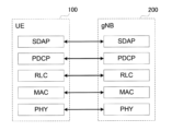
- FIG. 2 is a diagram showing the configuration of a protocol stack of a user plane wireless interface that handles data.
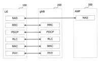
- FIG. 2 is a diagram showing the configuration of a protocol stack of a control plane radio interface that handles signaling (control signals).
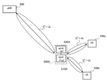
- FIG. 2 is a diagram illustrating an example of an application scenario of the relay device (NCR device) according to the first embodiment.
- FIG. 2 is a diagram illustrating an example of an application scenario of the relay device (NCR device) according to the first embodiment.
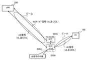
- FIG. 3 is a diagram illustrating an example of a method of controlling a relay device (NCR device) according to the first embodiment.
- FIG. 1 is a diagram showing an example of a configuration of a protocol stack in a mobile communication system having a relay device (NCR device) according to a first embodiment
- FIG. 1 is a diagram illustrating a configuration example of a relay device (NCR device) according to a first embodiment
- FIG. It is a diagram showing an example of the configuration of a base station (gNB) according to an embodiment.
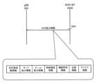
- FIG. 2 is a diagram showing an example of downlink signaling from a base station (gNB) to a control terminal (NCR-MT) according to the first embodiment.
- FIG. 2 is a diagram showing an example of uplink signaling from a control terminal (NCR-MT) to a base station (gNB) according to the first embodiment.
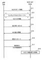
- FIG. 2 is a diagram showing an example of an overall operation sequence of the mobile communication system according to the first embodiment.
- FIG. 3 is a diagram for explaining beam sweeping according to the first embodiment.
- FIG. 2 is a diagram for explaining carrier aggregation (CA).
- FIG. 2 is a diagram for explaining dual connectivity (DC).
- FIG. 3 is a diagram illustrating a configuration example when CA is set in an NCR device (NCR-MT).
- NCR-MT NCR device
- FIG. 3 is a diagram illustrating a configuration example when setting a DC to an NCR device (NCR-MT).
- FIG. 3 is a diagram illustrating a first operation example in which multiple serving cells by CA according to the first embodiment are used in the NCR device.
- FIG. 3 is a diagram illustrating a first operation example in which multiple serving cells by the DC according to the first embodiment are used in the NCR device. It is a figure for explaining sCellDeactivationTimer.
- FIG. 7 is a diagram illustrating a third operation example in which multiple serving cells according to the first embodiment are used in the NCR device. It is a figure which shows the 4th example of operation which uses the multiple serving cell based on 1st Embodiment for an NCR apparatus.
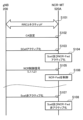
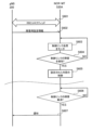
- FIG. 3 is a diagram illustrating a first operation example regarding failure handling of the NCR device according to the first embodiment.
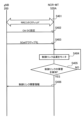
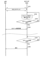
- FIG. 7 is a diagram illustrating a second operation example regarding failure handling of the NCR device according to the first embodiment.
- FIG. 7 is a diagram illustrating a third operation example regarding failure handling of the NCR device according to the first embodiment.
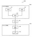
- FIG. 7 is a diagram for explaining a relay device according to a second embodiment.
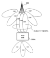
- FIG. 7 is a diagram for explaining a relay device according to a second embodiment.
- FIG. 7 is a diagram for explaining operations according to other embodiments.
- an object of the present disclosure is to enable appropriate control of a relay device that performs relay transmission between a base station and a user device.
- the relay device according to the first embodiment is a repeater device that can be controlled from a network.
- FIG. 1 is a diagram showing the configuration of a mobile communication system according to the first embodiment.
- the mobile communication system 1 complies with the 5th Generation System (5GS) of the 3rd Generation Partnership Project (3GPP) (registered trademark, same hereinafter) standard.
- 5GS will be described as an example below
- an LTE (Long Term Evolution) system may be applied at least partially to the mobile communication system.
- a sixth generation (6G) system may be applied at least in part to the mobile communication system.
- the mobile communication system 1 includes a user equipment (UE) 100, a 5G radio access network (NG-RAN) 10, and a 5G core network (5GC). work) 20 and have Below, the NG-RAN 10 may be simply referred to as RAN 10. Further, the 5GC 20 may be simply referred to as the core network (CN) 20.
- UE user equipment
- NG-RAN 5G radio access network
- 5GC 5G core network
- the UE 100 is a mobile wireless communication device.
- the UE 100 may be any device as long as it is used by a user.
- the UE 100 may be a mobile phone terminal (including a smartphone) and/or a tablet terminal, a notebook PC, a communication module (including a communication card or a chipset), a sensor or a device provided in the sensor, a vehicle or a device provided in the vehicle ( Vehicle UE), a flying object, or a device installed on a flying object (Aerial UE).
- the NG-RAN 10 includes a base station (called “gNB” in the 5G system) 200.
- gNB200 is mutually connected via the Xn interface which is an interface between base stations.
- gNB200 manages one or more cells.
- the gNB 200 performs wireless communication with the UE 100 that has established a connection with its own cell.
- the gNB 200 has a radio resource management (RRM) function, a routing function for user data (hereinafter simply referred to as "data”), a measurement control function for mobility control/scheduling, and the like.
- RRM radio resource management
- Cell is a term used to indicate the smallest unit of wireless communication area.
- Cell is also used as a term indicating a function or resource for performing wireless communication with the UE 100.
- One cell belongs to one carrier frequency (hereinafter simply referred to as "frequency").
- the gNB 200 may be functionally divided into a central unit (CU) and a distributed unit (DU).
- CU controls DU.
- the CU is a unit that includes upper layers included in a protocol stack described below, such as an RRC layer, an SDAP layer, and a PDCP layer.
- the CU is connected to the core network via the NG interface, which is a backhaul interface.
- the CU is connected to adjacent base stations via an Xn interface, which is an interface between base stations.
- DUs form cells.
- the DU 202 is a unit that includes lower layers included in a protocol stack described below, such as an RLC layer, a MAC layer, and a PHY layer.
- the DU is connected to the CU via the F1 interface, which is a fronthaul interface.
- the gNB can also be connected to EPC (Evolved Packet Core), which is the core network of LTE.
- EPC Evolved Packet Core
- LTE base stations can also connect to 5GC.
- An LTE base station and a gNB can also be connected via an inter-base station interface.
- 5GC20 includes an AMF (Access and Mobility Management Function) and a UPF (User Plane Function) 300.
- the AMF performs various mobility controls for the UE 100.
- AMF manages the mobility of UE 100 by communicating with UE 100 using NAS (Non-Access Stratum) signaling.
- the UPF controls data transfer.
- AMF and UPF are connected to gNB 200 via an NG interface that is a base station-core network interface.
- FIG. 2 is a diagram showing the configuration of a protocol stack of a user plane wireless interface that handles data.
- the user plane radio interface protocols include the physical (PHY) layer, MAC (Medium Access Control) layer, RLC (Radio Link Control) layer, and PDCP (Packet Data Convergence Protocol). col) layer and SDAP (Service Data Adaptation Protocol) It has a layer.
- PHY physical
- MAC Medium Access Control
- RLC Radio Link Control
- PDCP Packet Data Convergence Protocol
- col Packet Data Convergence Protocol
- SDAP Service Data Adaptation Protocol
- the PHY layer performs encoding/decoding, modulation/demodulation, antenna mapping/demapping, and resource mapping/demapping. Data and control information are transmitted between the PHY layer of the UE 100 and the PHY layer of the gNB 200 via a physical channel.
- the PHY layer of the UE 100 receives downlink control information (DCI) transmitted from the gNB 200 on the physical downlink control channel (PDCCH).
- DCI downlink control information
- the UE 100 performs blind decoding of the PDCCH using a radio network temporary identifier (RNTI), and acquires the successfully decoded DCI as the DCI addressed to its own UE.
- RNTI radio network temporary identifier
- a CRC parity bit scrambled by the RNTI is added to the DCI transmitted from the gNB 200.
- SSB Synchronization Signal/PBCH block
- SSB consists of four consecutive OFDM (Orthogonal Frequency Division Multiplex) symbols, including a primary synchronization signal (PSS), a secondary synchronization signal (SSS), a physical broadcast channel (PBCH)/master information block (MIB), and , PBCH demodulation reference signals (DMRS) are arranged.
- PSS primary synchronization signal
- SSS secondary synchronization signal
- PBCH physical broadcast channel
- MIB master information block
- DMRS PBCH demodulation reference signals
- the bandwidth of SSB is, for example, a bandwidth of 240 consecutive subcarriers, or 20RB.
- the MAC layer performs data priority control, retransmission processing using Hybrid ARQ (HARQ: Hybrid Automatic Repeat reQuest), random access procedure, etc.
- Data and control information are transmitted between the MAC layer of UE 100 and the MAC layer of gNB 200 via a transport channel.
- the MAC layer of gNB 200 includes a scheduler. The scheduler determines uplink and downlink transport formats (transport block size, modulation and coding scheme (MCS)) and resource blocks to be allocated to the UE 100.
- MCS modulation and coding scheme
- the RLC layer uses the functions of the MAC layer and PHY layer to transmit data to the RLC layer on the receiving side. Data and control information are transmitted between the RLC layer of UE 100 and the RLC layer of gNB 200 via logical channels.
- the PDCP layer performs header compression/expansion, encryption/decryption, etc.
- the SDAP layer performs mapping between an IP flow, which is a unit in which the core network performs QoS (Quality of Service) control, and a radio bearer, which is a unit in which an AS (Access Stratum) performs QoS control. Note that if the RAN is connected to the EPC, the SDAP may not be provided.
- QoS Quality of Service
- AS Access Stratum
- FIG. 3 is a diagram showing the configuration of the protocol stack of the wireless interface of the control plane that handles signaling (control signals).
- the protocol stack of the wireless interface of the control plane includes an RRC (Radio Resource Control) layer and a NAS (Non-Access Stratum) layer instead of the SDAP layer shown in FIG. 2.
- RRC Radio Resource Control
- NAS Non-Access Stratum
- RRC signaling for various settings is transmitted between the RRC layer of the UE 100 and the RRC layer of the gNB 200.
- the RRC layer controls logical, transport and physical channels according to the establishment, re-establishment and release of radio bearers.
- RRC connection connection between the RRC of the UE 100 and the RRC of the gNB 200
- the UE 100 is in an RRC connected state.
- RRC connection no connection between the RRC of the UE 100 and the RRC of the gNB 200
- the UE 100 is in an RRC idle state.
- the connection between the RRC of the UE 100 and the RRC of the gNB 200 is suspended, the UE 100 is in an RRC inactive state.
- the NAS layer located above the RRC layer performs session management, mobility management, etc.
- NAS signaling is transmitted between the NAS layer of the UE 100 and the NAS layer of the AMF 300A.
- the UE 100 has an application layer and the like in addition to the wireless interface protocol.
- a layer lower than the NAS layer is called an AS layer.
- FIGS. 4 and 5 are diagrams showing an example of an application scenario of the NCR device according to the first embodiment.
- 5G/NR is capable of wideband transmission using a high frequency band. Since radio signals in high frequency bands such as millimeter wave bands or terahertz wave bands have high straightness, reducing the coverage of the gNB 200 becomes an issue.
- the UE 100 may be located outside the coverage area of the gNB 200, for example, outside the area where wireless signals can be directly received from the gNB 200.
- a shield may exist between the gNB 200 and the UE 100, and the UE 100 may be unable to communicate within line of sight with the gNB 200.
- a mobile communication system uses a repeater device (500A), which is a type of relay device that relays wireless signals between the gNB 200 and the UE 100, and which can be controlled from a network. 1.
- a repeater device will be referred to as an NCR (Network-Controlled Repeater) device.
- NCR Network-Controlled Repeater
- Such a repeater device may be referred to as a smart repeater device.
- the NCR device 500A amplifies a wireless signal (radio wave) received from the gNB 200 and transmits it by directional transmission. Specifically, the NCR device 500A receives a wireless signal transmitted by the gNB 200 by beamforming. Then, the NCR device 500A amplifies the received radio signal without demodulating or modulating it, and transmits the amplified radio signal by directional transmission.
- the NCR device 500A may transmit a wireless signal with fixed directivity (beam).
- the NCR device 500A may transmit wireless signals using a variable (adaptive) directional beam. Thereby, the coverage of gNB 200 can be efficiently expanded.
- the NCR device 500A is applied to downlink communication from the gNB 200 to the UE 100, but the NCR device 500A can also be applied to uplink communication from the UE 100 to the gNB 200.
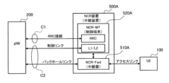
- a new UE (hereinafter referred to as "NCR-MT (Mobile termination)”) 520A which is a type of control terminal for controlling the NCR device 500A. That is, the NCR device 500A is a type of repeater that relays a wireless signal transmitted between the gNB 200 and the UE 100, and specifically changes the propagation state of the wireless signal without demodulating or modulating the wireless signal. It has an NCR-Fwd (Forward) 510A and an NCR-MT 520A that performs wireless communication with the gNB 200 and controls the NCR-Fwd 510A.
- NCR-MT Mobile termination
- the NCR-MT 520A controls the NCR device 500A in cooperation with the gNB 200 by establishing a wireless connection with the gNB 200 and performing wireless communication with the gNB 200. Thereby, efficient coverage expansion can be achieved using the NCR device 500A.
- NCR-MT520A controls NCR device 500A according to control from gNB200.
- the NCR-MT520A may be configured separately from the NCR-Fwd510A.
- the NCR-MT520A may be located near the NCR-Fwd510A and may be electrically connected to the NCR-Fwd510A.
- NCR-MT520A may be connected to NCR-Fwd510A by wire or wirelessly.
- the NCR-MT520A may be configured integrally with the NCR-Fwd510A.
- the NCR-MT 520A and the NCR-Fwd 510A may be fixedly installed, for example, at the coverage edge (cell edge) of the gNB 200, or on the wall or window of some building.
- the NCR-MT 520A and the NCR-Fwd 510A may be installed in, for example, a vehicle and may be movable. Further, one NCR-MT 520A may control a plurality of NCR-Fwds 510A.
- the NCR device 500A (NCR-Fwd 510A) dynamically or quasi-statically changes the beam it transmits or receives.
- the NCR-Fwd 510A forms a beam toward each of the UE 100a and UE 100b.
- the NCR-Fwd 510A may form a beam toward the gNB 200.
- the NCR-Fwd 510A transmits a radio signal received from the gNB 200 toward the UE 100a by beamforming, and/or beamforms a radio signal received from the UE 100a toward the gNB 200. Send by.
- NCR-Fwd 510A transmits a radio signal received from gNB 200 to UE 100b by beamforming, and/or transmits a radio signal received from UE 100b to gNB 200 by beamforming, in the communication resources between gNB 200 and UE 100b. do. Instead of or in addition to beam formation, the NCR-Fwd 510A performs null formation (towards a UE 100 (not shown) that is not a communication partner and/or a neighboring gNB 200 (not shown)) for interference suppression. So-called null steering) may also be used.
- FIG. 6 is a diagram illustrating an example of a method of controlling the NCR device 500A according to the first embodiment.
- the NCR-Fwd 510A relays a radio signal (also referred to as a "UE signal") between the gNB 200 and the UE 100.
- the UE signal includes an uplink signal (also referred to as a "UE-UL signal”) transmitted from the UE 100 to the gNB 200, and a downlink signal (also referred to as a "UE-DL signal”) transmitted from the gNB 200 to the UE 100.
- UE-UL signal uplink signal
- UE-DL signal downlink signal
- the NCR-Fwd 510A relays the UE-UL signal from the UE 100 to the gNB 200, and also relays the UE-DL signal from the gNB 200 to the UE 100.
- the wireless link between the NCR-Fwd 510A and the UE 100 is also referred to as an "access link.”
- the wireless link between the NCR-Fwd 510A and the gNB 200 is also referred to as a "backhaul link.”
- the NCR-MT 520A transmits and receives a wireless signal (herein referred to as "NCR-MT signal") with the gNB 200.
- the NCR-MT signal includes an uplink signal (referred to as “NCR-MT-UL signal”) transmitted from NCR-MT520A to gNB200 and a downlink signal (referred to as "NCR-MT-UL signal") transmitted from gNB200 to NCR-MT520A. DL signal).
- the NCR-MT-UL signal includes signaling for controlling the NCR device 500A.
- the wireless link between NCR-MT520A and gNB200 is also referred to as a "control link.”
- gNB200 directs the beam to NCR-MT520A based on the NCR-MT-UL signal from NCR-MT520A. Since the NCR device 500A is co-located with the NCR-MT520A, if the backhaul link and control link have the same frequency, when the gNB 200 directs the beam to the NCR-MT520A, the resulting The beam will also be directed to NCR-Fwd510A. gNB 200 transmits the NCR-MT-DL signal and UE-DL signal using the beam. NCR-MT520A receives the NCR-MT-DL signal.
- the NCR-Fwd510A and the NCR-MT520A have the function of transmitting/receiving or relaying the UE signal and/or the NCR-MT signal (for example, the antenna ) may be integrated.
- the beam includes a transmission beam and/or a reception beam. Beam is a general term for controlled transmission and/or reception to maximize the power of transmitted waves and/or received waves in a specific direction by adjusting/adapting antenna weights and the like.
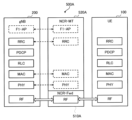
- FIG. 7 is a diagram showing a configuration example of a protocol stack in the mobile communication system 1 having the NCR device 500A according to the first embodiment.
- NCR-Fwd510A relays wireless signals transmitted and received between gNB200 and UE100.
- the NCR-Fwd 510A has an RF (Radio Frequency) function to amplify and relay received radio signals, and performs directional transmission by beamforming (eg, analog beamforming).
- RF Radio Frequency
- the NCR-MT 520A has at least one layer (entity) of PHY, MAC, RRC, and F1-AP (Application Protocol).
- F1-AP is a type of fronthaul interface.
- the NCR-MT 520A exchanges downlink signaling and/or uplink signaling, which will be described later, with the gNB 200 using at least one of PHY, MAC, RRC, and F1-AP. If the NCR-MT 520A is a type or part of a base station, the NCR-MT 520A may communicate with the gNB 200 through an Xn AP (Xn-AP) that is an interface between base stations.
- Xn-AP Xn AP
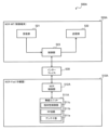
- FIG. 8 is a diagram showing a configuration example of the NCR device 500A, which is the relay device according to the first embodiment.
- the NCR device 500A includes an NCR-Fwd 510A, an NCR-MT 520A, and an interface 530.
- the NCR-Fwd 510A includes a wireless unit 511A and an NCR control section 512A.
- the wireless unit 511A includes an antenna section 511a including a plurality of antennas (multiple antenna elements), an RF circuit 511b including an amplifier, and a directivity control section 511c that controls the directivity of the antenna section 511a.
- the RF circuit 511b amplifies and relays (transmits) radio signals transmitted and received by the antenna section 511a.
- the RF circuit 511b may convert a radio signal, which is an analog signal, into a digital signal, and after digital signal processing, convert it back into an analog signal.
- the directivity control unit 511c may perform analog beamforming using analog signal processing.
- the directivity control unit 511c may perform digital beamforming using digital signal processing.
- the directivity control unit 511c may perform analog and digital hybrid beamforming.
- the NCR control section 512A controls the wireless unit 511A according to the control signal from the NCR-MT 520A.
- NCR control unit 512A may include at least one processor.
- the NCR control unit 512A may output information regarding the capabilities of the NCR device 500A to the NCR-MT 520A.
- the NCR-MT 520A includes a receiving section 521, a transmitting section 522, and a control section 523.
- the receiving unit 521 performs various types of reception under the control of the control unit 523.
- Receiving section 521 includes an antenna and a receiver.
- the receiver converts a radio signal (radio signal) received by the antenna into a baseband signal (received signal) and outputs the baseband signal (received signal) to the control unit 523.
- the transmitter 522 performs various types of transmission under the control of the controller 523.
- the transmitter 522 includes an antenna and a transmitter.
- the transmitter converts the baseband signal (transmission signal) output by the control unit 523 into a wireless signal and transmits it from the antenna.
- the control unit 523 performs various controls in the NCR-MT 520A.
- Control unit 523 includes at least one processor and at least one memory.
- the memory stores programs executed by the processor and information used in processing by the processor.
- the processor may include a baseband processor and a CPU (Central Processing Unit).
- the baseband processor performs modulation/demodulation, encoding/decoding, etc. of the baseband signal.
- the CPU executes programs stored in memory to perform various processes. Further, the control unit 523 executes functions of at least one layer of PHY, MAC, RRC, and F1-AP.
- the interface 530 electrically connects the NCR-Fwd 510A and the NCR-MT 520A.
- the control unit 523 of the NCR-MT 520A controls the NCR-Fwd 510A via the interface 530.
- the receiving unit 521 of the NCR-MT 520A receives signaling (downlink signaling) used to control the NCR device 500A from the gNB 200 via wireless communication.
- the control unit 523 of the NCR-MT 520A controls the NCR device 500A based on the signaling. This allows the gNB 200 to control the NCR-Fwd 510A via the NCR-MT 520A.
- control unit 523 of the NCR-MT 520A may transmit NCR capability information indicating the capability of the NCR device 500A to the gNB 200 via wireless communication.
- NCR capability information is an example of uplink signaling from NCR-MT 520A to gNB 200. This allows the gNB 200 to grasp the capabilities of the NCR device 500A.
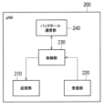
- FIG. 9 is a diagram showing a configuration example of the gNB 200 according to the first embodiment.
- gNB 200 includes a transmitting section 210, a receiving section 220, a control section 230, and a backhaul communication section 240.
- the transmitter 210 performs various transmissions under the control of the controller 230.
- Transmitter 210 includes an antenna and a transmitter.
- the transmitter converts the baseband signal (transmission signal) output by the control unit 230 into a wireless signal and transmits it from the antenna.
- the receiving unit 220 performs various types of reception under the control of the control unit 230.
- Receiving section 220 includes an antenna and a receiver.
- the receiver converts the radio signal received by the antenna into a baseband signal (received signal) and outputs it to the control unit 230.
- the transmitter 210 and the receiver 220 may be capable of beam forming using multiple antennas.
- Control unit 230 performs various controls in the gNB 200.
- Control unit 230 includes at least one processor and at least one memory.
- the memory stores programs executed by the processor and information used in processing by the processor.
- the processor may include a baseband processor and a CPU.
- the baseband processor performs modulation/demodulation, encoding/decoding, etc. of the baseband signal.
- the CPU executes programs stored in memory to perform various processes.
- the backhaul communication unit 240 is connected to adjacent base stations via an inter-base station interface.
- Backhaul communication unit 240 is connected to AMF/UPF 300 via a base station-core network interface.
- the gNB may be configured (that is, functionally divided) of a CU (Central Unit) and a DU (Distributed Unit), and the two units may be connected by an F1 interface.
- the transmitting unit 210 of the gNB 200 transmits signaling (downlink signaling) used for controlling the NCR-Fwd 510A to the NCR-MT 520A by wireless communication. This allows the gNB 200 to control the NCR device 500A via the NCR-MT 520A.
- the receiving unit 220 of the gNB 200 may receive NCR capability information indicating the capability of the NCR device 500A from the NCR-MT 520A via wireless communication.
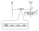
- FIG. 10 is a diagram showing an example of downlink signaling from the gNB 200 to the NCR-MT 520A according to the first embodiment.
- the gNB 200 transmits downlink signaling to the NCR-MT 520A.
- the downlink signaling may be an RRC message that is RRC layer (ie, layer 3) signaling.
- the downlink signaling may be MAC CE (Control Element), which is MAC layer (namely, layer 2) signaling.
- the downlink signaling may be downlink control information (DCI) that is PHY layer (ie, layer 1) signaling.
- DCI downlink control information
- PHY layer ie, layer 1 signaling.
- Downlink signaling may be UE-specific signaling.
- the downlink signaling may be broadcast signaling.
- the downlink signaling may be a fronthaul message (eg, an F1-AP message). If the NCR-MT 520A is a type or part of a base station, the NCR-MT 520A may communicate with the gNB 200 through an Xn AP (Xn-AP) that is an interface between base stations.
- Xn-AP Xn
- the gNB 200 transmits an NCR control signal specifying the operating state of the NCR device 500A as downlink signaling to the NCR-MT 520A that has established a wireless connection with the gNB 200 (step S1A).
- the NCR control signal specifying the operating state of the NCR device 500A may be MAC CE, which is MAC layer (layer 2) signaling, or DCI, which is PHY layer (layer 1) signaling.
- the NCR control signal may be included in an RRC Reconfiguration message, which is a type of UE-specific RRC message, and transmitted to the NCR-MT 520A.
- Downlink signaling may be a message of a layer higher than the RRC layer (for example, NCR application).
- Downlink signaling may be such that a message in a layer higher than the RRC layer is encapsulated in a message in a layer below the RRC layer and then transmitted.
- the NCR-MT 520A (transmission unit 522) may transmit a response message to downlink signaling from the gNB 200 on the uplink.
- the response message may be transmitted in response to the NCR device 500A completing the configuration specified in the downlink signaling or receiving the configuration.
- the NCR control signal may be referred to as Side Control Information.
- the NCR control signal may include frequency control information that specifies the center frequency of a wireless signal (for example, a component carrier) to be relayed by the NCR-Fwd 510A.
- the NCR-MT 520A controls the NCR-Fwd 510A to relay the radio signal of the center frequency indicated by the frequency control information ( Step S2A).
- the NCR control signal may include a plurality of frequency control information specifying mutually different center frequencies. Since the NCR control signal includes frequency control information, the gNB 200 can specify the center frequency of the wireless signal to be relayed by the NCR-Fwd 510A via the NCR-MT 520A.
- the NCR control signal may include mode control information that specifies the operation mode of the NCR-Fwd 510A.
- Mode control information may be associated with frequency control information (center frequency).
- the operating modes are a mode in which the NCR-Fwd510A performs omnidirectional transmission and/or reception, a mode in which the NCR-Fwd510A performs fixed directional transmission and/or reception, and a mode in which the NCR-Fwd510A performs variable directional beam.
- a mode in which the NCR-Fwd 510A performs MIMO (Multiple Input Multiple Output) relay transmission may be used.
- MIMO Multiple Input Multiple Output
- the operation mode may be either a beamforming mode (that is, a mode that emphasizes desired wave improvement) or a null steering mode (that is, a mode that emphasizes interference wave suppression).
- the NCR-MT 520A controls the NCR-Fwd 510A to operate in the operation mode indicated by the mode control information (step S2A). Since the NCR control signal includes mode control information, the gNB 200 can specify the operation mode of the NCR-Fwd 510A via the NCR-MT 520A.
- the mode in which the NCR device 500A performs omnidirectional transmission and/or reception is a mode in which the NCR-Fwd 510A performs relay in all directions, and may be referred to as omni mode.
- the mode in which the NCR-Fwd 510A performs fixed directional transmission and/or reception may be a directional mode realized by one directional antenna.
- the mode may be a beamforming mode realized by applying fixed phase/amplitude control (antenna weight control) to a plurality of antennas. Any of these modes may be designated (set) from the gNB 200 to the NCR-MT 520A.
- the mode in which the NCR-Fwd 510A performs transmission and/or reception using a variable directional beam may be a mode in which analog beamforming is performed.
- the mode may be a mode in which digital beamforming is performed.
- the mode may be a mode in which hybrid beamforming is performed.
- the mode may be a mode that forms an adaptive beam specific to the UE 100. Any of these modes may be designated (set) from the gNB 200 to the NCR-MT 520A. Note that in the beamforming operation mode, beam control information, which will be described later, may be provided from the gNB 200 to the NCR-MT 520A.
- the mode in which the NCR device 500A performs MIMO relay transmission may be a mode in which SU (Single-User) spatial multiplexing is performed.
- the mode may be a mode that performs MU (Multi-User) spatial multiplexing.
- the mode may be a mode that performs transmission diversity. Any of these modes may be designated (set) from the gNB 200 to the NCR-MT 520A.
- the operation modes may include a mode in which relay transmission by the NCR-Fwd 510A is turned on (activated) and a mode in which relay transmission by the NCR-Fwd 510A is turned off (deactivated). Any of these modes may be designated (set) from the gNB 200 to the NCR-MT 520A by an NCR control signal.
- the NCR control signal may include beam control information that specifies the transmission direction, transmission weight, or beam pattern when the NCR-Fwd 510A performs directional transmission.
- the beam control information may be associated with frequency control information (center frequency).
- the beam control information may include a PMI (Precoding Matrix Indicator).
- the beam control information may include beam forming angle information.
- the NCR-MT 520A controls the NCR-Fwd 510A to form a transmission directivity (beam) indicated by the beam control information (step S2A). Since the NCR control signal includes beam control information, the gNB 200 can control the transmission directivity of the NCR device 500A via the NCR-MT 520A.
- the NCR control signal may include output control information that specifies the degree to which the NCR-Fwd 510A amplifies the wireless signal (amplification gain) or the transmission power.
- the output control information may be information indicating a difference value (ie, relative value) between the current amplification gain or transmission power and the target amplification gain or transmission power. If the NCR control signal received from the gNB 200 includes output control information, the NCR-MT 520A (control unit 523) controls the NCR-Fwd 510A to change to the amplification gain or transmission power indicated by the output control information (step S2A). ).
- the output control information may be associated with frequency control information (center frequency).
- the output control information may be information specifying any one of the amplifier gain, beamforming gain, and antenna gain of the NCR-Fwd 510A.
- the output control information may be information specifying the transmission power of the NCR-Fwd 510A.
- the gNB 200 may transmit an NCR control signal to the NCR-MT 520A for each NCR-Fwd 510A.
- the NCR control signal may include the identifier (NCR identifier) of the corresponding NCR-Fwd 510A.
- the NCR-MT 520A (control unit 523) that controls the plurality of NCR-Fwds 510A determines the NCR-Fwd 510A to which the NCR control signal is applied based on the NCR identifier included in the NCR control signal received from the gNB 200. Note that the NCR identifier may be transmitted from the NCR-MT 520A to the gNB 200 together with the NCR control signal even when the NCR-MT 520A controls only one NCR-Fwd 510A.
- the NCR-MT 520A controls the NCR-Fwd 510A based on the NCR control signal from the gNB 200. This allows the gNB 200 to control the NCR-Fwd 510A via the NCR-MT 520A.
- FIG. 11 is a diagram showing an example of uplink signaling from the NCR-MT 520A to the gNB 200 according to the first embodiment.
- the NCR-MT 520A (transmission unit 210) transmits uplink signaling to the gNB 200.
- the uplink signaling may be an RRC message that is RRC layer signaling.
- the uplink signaling may be MAC CE, which is MAC layer signaling.
- the uplink signaling may be uplink control information (UCI) that is PHY layer signaling.
- the uplink signaling may be a fronthaul message (eg, an F1-AP message).
- the uplink signaling may be an inter-base station message (eg, an Xn-AP message).
- Uplink signaling may be a message of a layer higher than the RRC layer (for example, NCR application).
- Uplink signaling may encapsulate a message in a layer higher than the RRC layer with a message in a layer below the RRC layer, and then transmit the message. That is, uplink signaling stores upper layer messages in lower layer containers.
- the gNB 200 transmission unit 210) may transmit a response message to uplink signaling from the NCR-MT 520A on the downlink, and the NCR-MT 520A (reception unit 521) may receive the response message.
- the NCR-MT 520A (transmission unit 522) that has established a wireless connection with the gNB 200 transmits NCR capability information indicating the capability of the NCR device 500A to the gNB 200 as uplink signaling (step S5A).
- the NCR-MT 520A (transmission unit 522) may include NCR capability information in a UE Capability message or a UE Assistant Information message, which is a type of RRC message, and transmit the message to the gNB 200.
- the NCR-MT 520A (transmission unit 522) may transmit NCR capability information (NCR capability information and/or operating state information) to the gNB 200 in response to a request or inquiry from the gNB 200.
- the NCR capability information may include corresponding frequency information indicating the frequency supported by the NCR-Fwd 510A.
- the corresponding frequency information may be a numerical value or an index indicating the center frequency of the frequency corresponding to the NCR-Fwd 510A.
- the corresponding frequency information may be a numerical value or an index indicating the range of frequencies supported by the NCR-Fwd 510A. If the NCR capability information received from the NCR-MT 520A includes corresponding frequency information, the gNB 200 (control unit 230) can grasp the frequency supported by the NCR-Fwd 510A based on the corresponding frequency information. Then, the gNB 200 (control unit 230) may set the center frequency of the wireless signal targeted by the NCR device 500A within the frequency range supported by the NCR-Fwd 510A.
- the NCR capability information may include mode capability information regarding operation modes that can be supported by the NCR-Fwd 510A or switching between operation modes.
- the operating modes are a mode in which the NCR-Fwd510A performs omnidirectional transmission and/or reception, a mode in which the NCR-Fwd510A performs fixed directional transmission and/or reception, and a mode in which the NCR-Fwd510A performs fixed directional transmission and/or reception.
- the mode may be at least one of a mode in which transmission and/or reception is performed using a variable directional beam, and a mode in which the NCR-Fwd 510A performs MIMO (Multiple Input Multiple Output) relay transmission.
- MIMO Multiple Input Multiple Output
- the operation mode may be either a beamforming mode (that is, a mode that emphasizes desired wave improvement) or a null steering mode (that is, a mode that emphasizes interference wave suppression).
- the mode capability information may be information indicating which of these operation modes the NCR-Fwd 510A is compatible with.
- the mode capability information may be information indicating which of these operating modes can be switched between. If the NCR capability information received from the NCR-MT 520A includes mode capability information, the gNB 200 (control unit 230) can grasp the operation mode and mode switching supported by the NCR-Fwd 510A based on the mode capability information. Then, the gNB 200 (control unit 230) may set the operation mode of the NCR-Fwd 510A within the grasped operation mode and mode switching range.
- the NCR capability information may include beam capability information indicating a beam variable range, beam variable resolution, or variable pattern number when the NCR-Fwd 510A performs transmission and/or reception using a variable directional beam.
- the beam capability information may be, for example, information indicating a variable range of the beam angle (for example, controllable from 30° to 90°) with respect to the horizontal or vertical direction.
- the beam capability information may be information indicating an absolute angle.
- the beam capability information may be expressed by a direction and/or an elevation angle in which the beam is directed.
- the beam capability information may be information indicating an angle change for each variable step (for example, horizontal 5°/step, vertical 10°/step).
- the beam capability information may be information indicating a variable number of steps (for example, 10 horizontal steps, 20 vertical steps).
- the beam capability information may be information indicating the number of variable beam patterns in the NCR-Fwd 510A (for example, a total of 10 patterns of beam patterns 1 to 10). If the NCR capability information received from the NCR-MT 520A includes beam capability information, the gNB 200 (control unit 230) can grasp the beam angle change or beam pattern that the NCR-Fwd 510A can handle based on the beam capability information. Then, the gNB 200 (control unit 230) may set the beam of the NCR-Fwd 510A within the range of the determined beam angle change or beam pattern. These beam capability information may be null capability information. In the case of null capability information, these beam capability information indicate the null control capability when performing null steering.
- the NCR capability information may include control delay information indicating the control delay time in the NCR device 500A.
- the control delay information includes control according to the NCR control signal (change of operation mode and/or change of beam ) is information indicating the delay time (for example, 1 ms, 10 ms, etc.) until completion. If the NCR capability information received from the NCR-MT 520A includes control delay information, the gNB 200 (control unit 230) can grasp the control delay time in the NCR-Fwd 510A based on the control delay information.
- the NCR capability information may include amplification characteristic information regarding the amplification characteristic or output power characteristic of the wireless signal in the NCR-Fwd 510A.
- the amplification characteristic information may be information indicating the amplifier gain (dB), beamforming gain (dB), and antenna gain (dBi) of the NCR-Fwd510A.
- the amplification characteristic information may be information indicating a variable amplification range (for example, 0 dB to 60 dB) in the NCR-Fwd 510A.
- the amplification characteristic information may be information indicating the number of amplification steps (for example, 10 steps) that the NCR-Fwd 510A can change, or the amplification degree for each variable step (for example, 10 dB/step).
- the amplification characteristic information may be information indicating a variable range (for example, 0 dBm to 30 dBm) of the output power of the NCR-Fwd 510A.
- the amplification characteristic information may be information indicating the number of output power steps that the NCR-Fwd510A can change (for example, 10 steps) or the output power for each variable step (for example, 10 dBm/step or 10 dB/step). good.
- the NCR capability information may include location information indicating the installation location of the NCR device 500A.
- the location information may include one or more of latitude, longitude, and altitude.
- the position information may include information indicating the distance and/or installation angle of the NCR device 500A with respect to the gNB 200.
- the installation angle may be a relative angle with respect to the gNB 200, or may be a relative angle with respect to, for example, north, vertically, or horizontally.
- the installation position may be position information of a place where the antenna section 511a of the NCR-Fwd 510A is installed.
- the NCR capability information may include antenna information indicating the number of antennas that the NCR-Fwd 510A has.
- the antenna information may be information indicating the number of antenna ports that the NCR-Fwd 510A has.
- the antenna information may be information indicating the degree of freedom of directivity control (beam or null formation).
- the degree of freedom indicates how many beams can be formed (controlled), and is usually "(number of antennas) - 1". For example, in the case of two antennas, the degree of freedom is one. In the case of two antennas, a figure-eight beam pattern is formed, but since the directivity can only be controlled in one direction, the degree of freedom is one.
- the NCR-MT 520A may transmit NCR capability information to the gNB 200 for each NCR-Fwd 510A.
- the NCR capability information may include the number of NCR-Fwds 510A and/or the identifier (NCR identifier) of the corresponding NCR-Fwds 510A.
- the NCR-MT520A controls a plurality of NCR-Fwd510A
- the NCR-MT520A indicates at least one of the identifier of each of the plurality of NCR-Fwd510A and the number of the plurality of NCR-Fwd510A. You may also send information.
- the NCR identifier may be transmitted from the NCR-MT 520A to the gNB 200 together with the NCR capability information even if the NCR-MT 520A controls only one NCR-Fwd 510A.
- FIG. 12 is a diagram showing an example of the overall operation sequence of the mobile communication system 1 according to the first embodiment.
- sequence diagrams referred to in the following embodiments non-essential steps are shown with broken lines.
- NCR in FIG. 12 may be replaced with "RIS”.
- the gNB 200 (transmission unit 210) broadcasts NCR support information indicating that the gNB 200 supports the NCR-MT 520A.
- the gNB 200 (transmitter 210) broadcasts a system information block (SIB) that includes NCR support information.
- SIB system information block
- NCR support information may be information indicating that NCR-MT520A is accessible.
- the gNB 200 (transmission unit 210) may broadcast NCR non-support information indicating that the gNB 200 does not support the NCR-MT 520A.
- the NCR non-support information may be information indicating that the NCR-MT 520A is inaccessible.
- the NCR-MT 520A may be in an RRC idle state or an RRC inactive state.
- the NCR-MT520A (control unit 523), which has not established a wireless connection with the gNB200, determines that access to the gNB200 is permitted in response to receiving the NCR support information from the gNB200, and establishes a wireless connection with the gNB200. An access operation may be performed to establish the .
- the NCR-MT 520A (control unit 523) may perform cell reselection by regarding the gNB 200 (cell) to which access is permitted as having the highest priority.
- the NCR-MT 520A (control unit 523) that has not established a wireless connection with the gNB 200 It may be determined that access (connection establishment) is not possible. Thereby, the NCR-MT 520A can establish a wireless connection only to the gNB 200 that can handle the NCR-MT 520A.
- the gNB 200 may broadcast access restriction information that restricts access from the UE 100.
- the NCR-MT 520A can also be regarded as an entity on the network side. Therefore, the NCR-MT 520A may ignore the access restriction information from the gNB 200. For example, when the NCR-MT520A (control unit 523) receives NCR support information from a gNB200, the NCR-MT520A (control unit 523) may perform an operation to establish a wireless connection with the gNB200 even if the gNB200 is broadcasting access restriction information. good.
- the NCR-MT 520A (control unit 523) does not need to execute (or may ignore) UAC (Unified Access Control).
- UAC Unified Access Control
- a special value may be used for one or both of AC/AI (Access Category/Access Identity) used in the UAC to indicate NCR-MT access.
- step S12 the NCR-MT 520A (control unit 523) starts a random access procedure for the gNB 200.
- the NCR-MT 520A transmission unit 522 transmits a random access preamble (Msg1) and an RRC message (Msg3) to the gNB 200.
- the NCR-MT 520A receiving unit 521) receives a random access response (Msg2) and an RRC message (Msg4) from the gNB 200.
- the NCR-MT 520A may transmit NCR-MT information indicating that the own UE is an NCR-MT to the gNB 200 when establishing a wireless connection with the gNB 200.
- the NCR-MT 520A includes NCR-MT information in a message for the random access procedure (for example, Msg1, Msg3, Msg5) and transmits the message to the gNB 200.
- the gNB 200 (control unit 230) recognizes that the accessed UE 100 is the NCR-MT 520A based on the NCR-MT information received from the NCR-MT 520A.
- the gNB 200 (control unit 230) can, for example, remove the NCR-MT 520A from the access restriction target (that is, accept access). Once the random access procedure is completed, the NCR-MT 520A transitions from the RRC idle state or RRC inactive state to the RRC connected state.
- step S14 the gNB 200 (transmission unit 522) transmits a capability inquiry message to the NCR-MT 520A, inquiring about the capabilities of the NCR-MT 520A.
- the NCR-MT 520A (receiving unit 521) receives the capability inquiry message.
- the NCR-MT 520A transmits a capability information message including NCR capability information to the gNB 200.
- the capability information message may be an RRC message, for example a UE Capability message.
- gNB 200 (receiving unit 220) receives the capability information message.
- the gNB 200 (control unit 230) grasps the capability of the NCR device 500A based on the received capability information message.
- the gNB 200 transmits a configuration message including various settings regarding the NCR device 500A to the NCR-MT 520A.
- the NCR-MT 520A receives the configuration message.
- the configuration message is a type of downlink signaling described above.
- the configuration message may be an RRC message, for example, an RRC Reconfiguration message.
- the gNB 200 transmits a control instruction specifying the operating state of the NCR-Fwd 510A to the NCR-MT 520A.
- the control instruction may be the above-mentioned NCR control signal (for example, L1/L2 signaling).
- the NCR-MT 520A (receiving unit 521) receives the control instruction.
- NCR-MT 520A (control unit 523) controls NCR-Fwd 510A according to control instructions.
- the NCR-MT 520A controls the NCR device 500A according to the above settings (and control instructions).
- the NCR-MT 520A may autonomously control the NCR device 500A without depending on control instructions from the gNB 200.
- the NCR-MT 520A may autonomously control the NCR device 500A based on the location of the UE 100 and/or information received by the NCR-MT 520A from the UE 100.
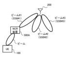
- FIG. 13 is a diagram for explaining beam sweeping according to the embodiment.
- the gNB 200 performs beam sweeping in which beams are sequentially switched and transmitted in different directions. At this time, the gNB 200 transmits a different SSB for each beam.
- the SSB is periodically transmitted from the gNB 200 into the cell as an SSB burst consisting of a plurality of SSBs. A plurality of SSBs within one SSB burst are each given an SSB index, which is an identifier.
- the SSBs are beamformed and transmitted in different directions.
- the NCR device 500A (NCR-MT 520A) reports to the gNB 200 during the random access channel (RACH) procedure which direction the beam received had good reception quality.
- RACH random access channel
- the NCR device 500A (NCR-MT 520A) transmits a random access preamble to the gNB 200 on a random access channel (RACH) occasion associated with an SSB index with good beam reception quality.
- RACH random access channel
- the gNB 200 can determine the optimum beam for the NCR device 500A (NCR-MT520A).
- SSB may be transmitted in the initial BWP (initial DL BWP).
- a dedicated BWP may be configured and activated on the NCR device 500A (NCR-MT520A).
- CSI-RS channel state information reference signal
- an example in which beam information for identifying a beam is an SSB index will be mainly described on the premise that there is a one-to-one relationship between a beam and an SSB (specifically, an SSB index).
- the beam may be associated with a CSI-RS.
- the beam information identifying the beam may be a CSI-RS index.
- the gNB 200 connects multiple serving cells to the NCR device 500A (NCR-MT520A) by carrier aggregation (CA) or dual connectivity (DC). ) can be set. Prior to explaining such operations, general CA and DC will be explained.
- CA carrier aggregation
- DC dual connectivity
- FIG. 14 is a diagram for explaining CA.
- CA multiple component carriers (CCs) corresponding to multiple serving cells are aggregated, and the UE 100 can receive or transmit simultaneously using multiple CCs.
- the plurality of CCs may be continuous in the frequency direction.
- the plurality of CCs may be discontinuous.
- the UE 100 has only one RRC connection with the network (for example, gNB 200).
- the network for example, gNB 200.
- one serving cell provides NAS mobility information
- RRC connection re-establishment/handover one serving cell provides security input.
- the one serving cell is called a primary cell (PCell).
- SCell secondary cell
- a set of serving cells can be formed. Therefore, the set of serving cells configured in the UE 100 is always composed of one PCell and one or more SCells. Reconfiguration, addition, and deletion of SCells can be performed by RRC.
- the primary cell is an MCG cell operating on the primary frequency in which the UE 100 performs an initial connection establishment procedure or initiates a connection re-establishment procedure.
- the UE 100 receives an RRCSetup message from a cell in the initial connection establishment procedure, the UE 100 considers the cell to be the primary cell.
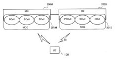
- FIG. 15 is a diagram for explaining DC.
- the UE 100 communicates with a master cell group (MCG) 201M managed by a master node (MN) 200M and a secondary cell group (SCG) 201S managed by a secondary node (SN) 200S.
- MCG master cell group
- SCG secondary cell group
- SN secondary node
- the MN 200M and SN 200S are connected to each other via a network interface (specifically, an inter-base station interface).
- the network interface may be an Xn interface or an X2 interface.
- the MN 200M may be referred to as a master base station
- the SN 200S may be referred to as a secondary base station.
- an example will be described in which both the MN 200M and the SN 200S are gNBs 200, but at least one of the MN 200M and the SN 200S may be an LTE base station (eNB).
- eNB LTE base station
- the DC is started when the MN 200M sends a predetermined message (for example, an SN Addition Request message) to the SN 200S, and the MN 200M sends an RRC Reconfiguration message to the UE 100.
- the UE 100 in the RRC connected state is allocated radio resources by the respective schedulers of the MN 200M and the SN 200S, and performs radio communication using the radio resources of the MN 200M and the radio resources of the SN 200S.
- the MN 200M may have a control plane connection with the core network.
- the MN 200M provides the main radio resources for the UE 100.
- MN200M manages MCG201M.
- MCG 201M is a group of serving cells associated with MN 200M.
- MCG201M has a primary cell (PCell) and optionally has one or more secondary cells (SCell).
- the SN 200S may not have a control plane connection with the core network.
- SN200S provides additional radio resources to UE100.
- SN200S manages SCG201S.
- the SCG 201S has a primary/secondary cell (PSCell), and optionally has one or more SCells. Note that the PCell of the MCG 201M and the PSCell of the SCG 201S are sometimes referred to as special cells (SpCell).
- FIG. 16 is a diagram illustrating a configuration example when CA is set in the NCR device 500A (NCR-MT 520A).
- control link ie, the wireless link between NCR-MT 520A and gNB 200
- backhaul link ie, the wireless link between NCR-Fwd 510A and gNB 200
- This frequency is also referred to as a "predetermined frequency.”
- channel conditions can be made uniform between the control link and the backhaul link, and the control of the NCR-Fwd 510A can be simplified.
- the gNB 200 grasps the channel state of the backhaul link and performs appropriate beamforming and link adaptation (determination of MCS, etc.) for the backhaul link. )It can be performed.
- the gNB 200 sets the cell C2 corresponding to the frequency of the radio signal (from another perspective, component carrier) relayed by the NCR device 500A to the NCR device 500A. (NCR-MT520A). This frequency is also referred to as "the operating frequency of NCR-Fwd510A.”
- the serving cell C2 is used for control links and backhaul links.
- NCR-MT 520A communicates with gNB 200 via a control link at layer 1 and/or layer 2 (L1/L2).
- the frequency of the serving cell C2 may be a frequency of a millimeter wave band (also referred to as "FR (Frequency Range) 2"). It is difficult to achieve stable wireless communication in such high frequency bands. Therefore, in the embodiment, by setting the serving cell C1, which has a frequency different from that of the serving cell C2, in the NCR device 500A (NCR-MT520A), it is possible to provide an RRC connection belonging to layer 3 (L3) on a different frequency. . This allows the control link and RRC connection to be separated.
- the serving cell C1 may have a frequency lower than the frequency of the serving cell C2, for example, a frequency in the Sub-6 band (also referred to as "FR1").
- serving cell C1 is a primary cell and serving cell C2 is a secondary cell. This makes it possible to stabilize the RRC connection of the NCR-MT520A while simplifying the control of the NCR-Fwd510A.
- FIG. 17 is a diagram illustrating a configuration example when setting the DC to the NCR device 500A (NCR-MT520A).
- serving cell C1 is provided in MN (gNB) 200M, and serving cell C2 is provided in SN (gNB) 200S.
- serving cell C1 is a primary cell belonging to MCG 201M of MN 200M.
- the serving cell C2 is a secondary cell belonging to the SCG 201S of the SN 200S.
- the NCR-Fwd 510A relays a radio signal of a predetermined frequency transmitted between the gNB 200 and the UE 100.
- NCR-MT520A performs wireless communication with gNB200 and controls NCR-Fwd510A.
- a plurality of serving cells including cell C1 corresponding to a predetermined frequency are set in NCR-MT 520A by gNB 200.
- cell C2 corresponding to the predetermined frequency is a secondary cell.
- the secondary cell may be a primary secondary cell (PSCell) in the DC.
- the secondary cell may be inactive (that is, not used for communication) at the time it is set.
- the NCR-MT 520A configured with a secondary cell may receive an activation instruction to activate the secondary cell from the gNB 200.
- the NCR-MT 520A may activate the operation of the NCR-Fwd 510A, that is, make it usable for relaying. This allows the operation of the NCR-Fwd 510A to be inactive while the secondary cell is inactive, thereby suppressing power consumption and unexpected interference caused by the NCR-Fwd 510A.
- the NCR-MT 520A may receive a deactivation instruction to deactivate the secondary cell from the gNB 200.
- the NCR-MT 520A may deactivate the operation of the NCR-Fwd 510A in response to receiving the activation instruction.
- the MN 200M may transmit information regarding the NCR device 500A to the SN 200S on the network interface (inter-base station interface). For example, the MN 200M may transmit information indicating that the SCG for the NCR device 500A is being added to the SN 200S at the time of SN Addition. The MN 200M may transmit the cell ID (that is, the cell identifier of the cell C2) associated with the NCR-Fwd 510A to the SN 200S. This makes it easy to implement the operation shown in FIG. 17.
- a primary cell is used for the RRC connection between the gNB 200 and the NCR-MT 520A.
- a secondary cell is used for the control link between gNB 200 and NCR-MT 520A. This makes it possible to have different frequencies for the control link and the RRC connection (ie, to separate the control link and the RRC connection).
- the NCR-MT 520A may receive an RRC message including configuration information for configuring a secondary cell from the gNB 200.
- the configuration information may include information that associates the secondary cell with the NCR-Fwd 510A.
- the NCR-MT 520A may receive a control signal for controlling the NCR-Fwd 510A (that is, the above-mentioned NCR control signal) from the gNB 200 via the control link.
- the NCR control signal may include identification information for identifying the NCR-Fwd 510A. This makes it possible to explicitly specify the NCR-Fwd 510A to be controlled, even if, for example, the NCR device 500A has a plurality of NCR-Fwds 510A.
- FIG. 18 is a diagram showing a first operational example using multiple serving cells by CA in the NCR device 500A.
- step S101 the NCR-MT 520A establishes an RRC connection with the gNB 200 and enters the RRC connected state.
- the primary cell (serving cell C1) of the gNB 200 is assigned to the NCR-MT 520A.
- the NCR-MT 520A may transmit the above-mentioned NCR capability information to the gNB 200.
- the NCR capability information may include information indicating that control of the NCR-Fwd 510A by the secondary cell is supported.
- the gNB 200 performs CA settings for the NCR-MT 520A.
- the gNB 200 transmits an RRC message (for example, an RRC Reconfiguration message) including CA configuration information to the NCR-MT 520A on the primary cell (serving cell C1).
- NCR-MT520A receives CA configuration information.
- the CA configuration information includes information that associates the secondary cell (serving cell C2) configured in the NCR-MT 520A with the NCR-Fwd 510A.
- the CA configuration information may include a list of at least one set of the secondary cell (serving cell C2) identifier and the NCR-Fwd 510A identifier.
- the CA configuration information may include information indicating which secondary cell (serving cell C2) controls the NCR-MT 520A (that is, establishes a control link).
- the gNB 200 transmits a secondary cell activation instruction to the NCR-MT 520A.
- the gNB 200 transmits a MAC CE including the activation instruction to the NCR-MT 520A on the primary cell (serving cell C1).
- NCR-MT520A receives the activation instruction.
- the activation instruction may include an identifier of the secondary cell to be activated.
- the NCR-MT 520A activates the secondary cell (serving cell C2) set in step S102 in response to receiving the activation instruction. Additionally, the NCR-MT 520A may activate the NCR-Fwd 510A. Upon activating the secondary cell (serving cell C2), the NCR-MT 520A starts beam selection and CSI feedback in the secondary cell (serving cell C2). Note that the secondary cell activation instruction and the NCR-Fwd 510A activation instruction may be different signaling. In this case, the NCR-MT 520A may activate the secondary cell when receiving the activation instruction for the secondary cell, and may activate the NCR-Fwd 510A when receiving the activation instruction for the NCR-Fwd 510A.
- step S105 the gNB 200 transmits the NCR control signal (L1/L2 signal) to the NCR-MT 520A on the control link in the secondary cell (serving cell C2).
- NCR-MT520A receives the NCR control signal (L1/L2 signal).
- the NCR control signal may include an identifier of the NCR-Fwd 510A.
- step S106 the NCR-MT 520A controls the NCR-Fwd 510A according to the NCR control signal received in step S105.
- the gNB 200 transmits a secondary cell deactivation instruction to the NCR-MT 520A.
- the gNB 200 transmits the MAC CE including the deactivation instruction to the NCR-MT 520A on the primary cell (serving cell C1) or the secondary cell (serving cell C2).
- NCR-MT520A receives the deactivation instruction.
- the deactivation instruction may include an identifier of the secondary cell to be deactivated.
- the NCR-MT 520A deactivates the secondary cell (serving cell C2) activated in step S104 in response to receiving the deactivation instruction. Additionally, the NCR-MT 520A may deactivate the NCR-Fwd 510A. Upon deactivating the secondary cell (serving cell C2), the NCR-MT 520A ends beam selection and CSI feedback in the secondary cell (serving cell C2). Note that the instruction to deactivate the secondary cell and the instruction to deactivate the NCR-Fwd 510A may be different signaling. In this case, the NCR-MT520A may deactivate the secondary cell when receiving the secondary cell deactivation instruction, and may deactivate the NCR-Fwd510A when receiving the NCR-Fwd510A deactivation instruction. .
- FIG. 19 is a diagram showing a first operation example in which multiple serving cells by DC are used in the NCR device 500A. Duplicate explanations of operations similar to those in the case of CA described above will be omitted.
- step S201 the NCR-MT 520A establishes an RRC connection with the MN 200M (gNB 200) and enters the RRC connected state.
- the primary cell (serving cell C1) of MN200M is assigned to NCR-MT520A.
- the NCR-MT 520A may transmit the above-mentioned NCR capability information to the gNB 200.
- the NCR capability information may include information indicating that control of the NCR-Fwd 510A by the secondary cell is supported.
- the SN 200S may transmit an SN Addition Required message to the MN 200M to request that an SN be added.
- the message may include information indicating that an NCR is requested to be added.
- the MN 200M may execute step S202 in response to receiving the message.
- the MN 200M transmits an SN Addition Request message to the SN 200S on the inter-base station interface.
- the SN 200S receives the SN Addition Request message.
- the SN Addition Request message may include information indicating that an SCG for controlling the NCR device 500A is to be added.
- the SN Addition Request message may include information that associates the NCR-Fwd 510A with the secondary cell.
- the SN Addition Request message may include a list including at least one set of an identifier of the NCR-Fwd 510A, an identifier of the NCR device 500A, and/or an identifier of the NCR-MT 520A and a cell ID.
- the SN Addition Request message may include a list including at least one set of an identifier of the NCR-Fwd 510A, an identifier of the NCR device 500A, and/or an identifier of the NCR-MT 520A and a frequency identifier.
- the SN 200S transmits an SN Addition Request Acknowledgment message including the RRC Reconfiguration (RRC container) to be transmitted to the NCR-MT 520A to the MN 200M on the inter-base station interface.
- the MN 200M receives the SN Addition Request Acknowledgment message.
- the RRC Reconfiguration (RRC container) includes DC configuration information.
- the DC configuration information includes information that associates the secondary cell (serving cell C2) configured in the NCR-MT 520A with the NCR-Fwd 510A.
- the DC configuration information may include a list of at least one set of the secondary cell (serving cell C2) identifier and the NCR-Fwd 510A identifier.
- the DC configuration information may include information indicating which secondary cell (serving cell C2) controls the NCR-MT 520A (that is, establishes a control link).
- the DC setting information may include information indicating the operating frequency of the NCR-Fwd 510A.
- step S204 the MN 200M transmits the RRC Reconfiguration (DC configuration information) included in the SN Addition Request Acknowledgment message received in step S203 to the NCR-MT 520A.
- RRC Reconfiguration DC configuration information
- steps S205 to S210 are similar to the operations in steps S103 to S108 in FIG. 18.
- the secondary cell activation instruction/deactivation instruction may be transmitted from the SN 200S to the NCR-MT 520A.
- the SN 200S may transmit a message requesting activation or deactivation of the NCR to the MN 200M.
- the MN 200M may execute step S205 or S209.
- the SN 200S may request the MN 200M to remove the NCR settings.
- the MN 200M may transmit an SN Removal Request message to the SN 200S.
- the message may be a message for removing the settings of the NCR device 500A.
- the message may be a message for removing the settings of the NCR-Fwd 510A.
- This operation example is an operation example related to a secondary cell deactivation timer (also referred to as "sCellDeactivationTimer").
- sCellDeactivationTimer is a timer that the gNB 200 sets in the UE 100 in association with the secondary cell.
- the sCellDeactivationTimer is a timer for deactivating the secondary cell in response to a predetermined period of time in which there is no data communication in the secondary cell, and is used to measure the predetermined time. This allows unused secondary cells to be voluntarily deactivated.
- FIG. 20 is a diagram for explaining sCellDeactivationTimer.
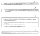
- "A” to “C” in FIG. 20 indicate the contents of the 3GPP technical specification “TS38.321” (i.e., MAC protocol specification), and “D” in FIG. 20 indicates the contents of the 3GPP technical specification "TS38.331” ( In other words, the contents of the RRC protocol specification are shown.
- the UE100 which is set with SCELLDEACTIVATIONTIMER, is a secondary SCE (SCE (SCE LL) does not activate.
- SCE SCE LL
- sCellDeactivationTimer can be individually set for each secondary cell (SCell).
- the UE 100 to which the sCellDeactivationTimer is set starts or restarts the sCellDeactivationTimer in response to activation of the secondary cell (SCell) associated with the sCellDeactivationTimer. Start.
- the UE100 which is set up with the ScellDeaCTIVATIONTIMER, has the PDCCH or the secondaricel (Scellelle) of the secondary cell (Scell) compatible with the ScellDEACTIVATIONTIMER. Resource on the serving cell to schedule
- the sCellDeactivationTimer is restarted. Further, the UE 100 restarts the sCellDeactivationTimer in response to receiving or transmitting data (MAC PDU) using the downlink or uplink resources allocated in advance in the configured grant.
- MAC PDU data
- the UE 100 applies infinity as the timer value of the sCellDeactivationTimer of the secondary cell.
- the NCR-MT 520A in the secondary cell that is, when providing a control link for the NCR-MT 520A in the secondary cell (serving cell C2)
- the following problems occur. Specifically, if sCellDeactivationTimer is set in the secondary cell (serving cell C2), there is a concern that the secondary cell (serving cell C2) will be deactivated due to expiration of sCellDeactivationTimer. For example, if the NCR control signal received on the control link is MAC CE, or if the NCR control signal received on the control link is DCI for non-scheduling, the NCR-MT520A will not be able to receive the NCR control signal.
- the gNB 200 that sets the secondary cell (serving cell C2) associated with the NCR-Fwd 510A to the NCR-MT 520A does not set sCellDeactivationTimer to the secondary cell. That is, the gNB 200 avoids setting the SCell deactivation timer on the secondary cell forming the control link of the NCR-Fwd 510A (setting the sCellDeactivationTimer on the secondary cell is prohibited). As a result, since the NCR-MT 520A applies an infinite value as the timer value of sCellDeactivationTimer, it is possible to prevent the secondary cell (serving cell C2) from being deactivated by sCellDeactivationTimer.
- the NCR-MT520A uses the timer value of the sCellDeactivationTimer (that is, the set sCellDeactivationTimer r) and set it to infinity as the timer value of sCellDeactivationTimer. may be applied. This can prevent the secondary cell (serving cell C2) from being deactivated by the sCellDeactivationTimer.
- FIG. 21 is a diagram showing this operation example. Duplicate explanations of operations similar to the first and second operation examples described above will be omitted.
- step S301 the NCR-MT 520A establishes an RRC connection with the gNB 200 and enters the RRC connected state.
- the primary cell (serving cell C1) of MN200M is assigned to NCR-MT520A.
- the gNB 200 performs CA settings or DC settings for the NCR-MT 520A.
- the gNB 200 sets the secondary cell (serving cell C2) that controls the NCR-Fwd 510A in the NCR-MT 520A.
- the settings include a set timer value of sCellDeactivationTimer.
- the settings may include information specifying whether to restart the sCellDeactivationTimer when receiving an NCR control signal (L1/L2 signal), particularly a DCI for NCR control.
- the information may include the cell ID of the secondary cell (serving cell C2) and/or the identifier of the NCR-Fwd 510A.
- step S303 the gNB 200 transmits a secondary cell (serving cell C2) activation instruction to the NCR-MT 520A.
- step S304 the NCR-MT 520A (or NCR device 500A) activates the secondary cell (serving cell C2) and the NCR-Fwd 510A in response to receiving the activation instruction. Furthermore, the NCR-MT 520A starts the sCellDeactivationTimer set for the secondary cell (serving cell C2) in step S302.
- step S306 the gNB 200 transmits the NCR control signal (L1/L2 signal) to the NCR-MT 520A on the control link in the secondary cell (serving cell C2).
- step S307 the NCR-MT 520A controls the NCR-Fwd 510A according to the NCR control signal. Furthermore, in response to receiving the NCR control signal (L1/L2 signal), the NCR-MT 520A restarts the sCellDeactivationTimer set for the secondary cell (serving cell C2) in step S302.
- the NCR-MT 520A deactivates the secondary cell (serving cell C2) when the sCellDeactivationTimer expires (step S308: YES). Further, the NCR-MT 520A (or NCR device 500A) may deactivate the corresponding NCR-Fwd 510A.
- the NCR-MT 520A detects that a failure has occurred in the control link (ie, secondary cell). NCR-MT 520A transmits information regarding the detected failure to gNB 200 on the primary cell. This allows the gNB 200 to understand that a failure has occurred in the control link.
- FIG. 22 is a diagram showing this operation example. Duplicate explanations of operations similar to the first to third operation examples described above will be omitted.
- step S401 the NCR-MT 520A establishes an RRC connection with the gNB 200 and enters the RRC connected state.
- the primary cell (serving cell C1) of MN200M is assigned to NCR-MT520A.
- the gNB 200 performs CA settings or DC settings for the NCR-MT 520A.
- the settings may include settings for monitoring the control link (eg, a quality threshold for the control link).
- the gNB 200 sets the secondary cell (serving cell C2) that controls the NCR-Fwd 510A in the NCR-MT 520A.
- step S403 the gNB 200 transmits a secondary cell (serving cell C2) activation instruction to the NCR-MT 520A.
- the NCR-MT 520A activates the secondary cell (serving cell C2) and the NCR-Fwd 510A in response to receiving the activation instruction.
- the NCR-MT 520A monitors the reception quality of the reference signal (SSB and/or CSI-RS) received on the control link.
- the NCR-MT 520A may perform the monitoring only when configured by the gNB 200.
- the reception quality may be RSRP/RSRQ/SINR of the control link.
- the NCR-MT 520A determines whether a failure of the control link is detected.
- the NCR-MT 520A may determine whether a failure corresponding to a radio link failure (RLF) has occurred in the control link.
- the NCR-MT 520A may determine that a failure has occurred when the measured reception quality is below a threshold.
- the threshold value may be set from the gNB 200.
- step S406 the NCR-MT 520A notifies the gNB 200 of control link failure information on the primary cell.
- the NCR-MT 520A transmits an RRC message such as an NCR Failure Information message to the gNB 200.
- gNB200 receives the message.
- the message may include an identifier of the NCR-Fwd 510A corresponding to the control link in which the failure has occurred, an identifier of the secondary cell, and/or information on the frequency in which the failure has occurred.
- the NCR-Fwd 510A relays the wireless signal transmitted between the gNB 200 and the UE 100.
- NCR-MT 520A performs wireless communication with gNB 200 via a control link to control NCR-Fwd 510A.
- the NCR-MT 520A performs predetermined control according to the failure.
- the NCR-MT 520A may transmit failure information of the control link or failure information of the NCR-Fwd 510A to the gNB 200 on the primary cell.
- the NCR-MT 520A detects that a failure has occurred in the control link.
- the NCR-MT 520A stops the operation of the NCR-Fwd 510A in response to the occurrence of a control link failure. If a failure occurs in the control link and the NCR-Fwd 510A operates in an uncontrolled state, problems such as interference may occur. Therefore, by stopping the operation of the NCR-Fwd 510A, the occurrence of such a problem can be avoided.
- the NCR-MT 520A may detect that the failure of the control link has been resolved.
- the NCR-MT 520A may send a notification to the gNB 200 in response to the resolution of the failure.
- FIG. 23 is a diagram showing this operation example. Duplicate explanations of operations similar to those of the above-described embodiments will be omitted.
- step S501 the NCR-MT 520A establishes an RRC connection with the gNB 200 and enters the RRC connected state.
- the gNB 200 may transmit an NCR control signal (L1/L2 signal) to the NCR-MT 520A on the control link.
- the NCR-MT 520A controls the NCR-Fwd 510A according to the NCR control signal.
- the NCR-MT 520A may monitor the reception quality of the reference signal (SSB and/or CSI-RS) received on the control link.
- the NCR-MT 520A may perform the monitoring only when configured by the gNB 200.
- the reception quality may be RSRP/RSRQ/SINR of the control link.
- the NCR-MT 520A determines whether a failure of the control link is detected.
- the NCR-MT 520A may determine whether a failure corresponding to a radio link failure (RLF) has occurred in the control link.
- the NCR-MT 520A may determine that a failure has occurred when the measured reception quality is below a threshold.
- the threshold value may be set from the gNB 200.
- the NCR-MT520A may determine that a control link failure has been detected if any of the following events occur: - A failure equivalent to RLF has occurred in the control link. - RLF has occurred in the primary cell. - RRC Reestablishment has started. - MCG Failure Information regarding MCG failure has been sent to gNB 200. - SCG Failure regarding SCG failure has occurred. Information has been sent to the gNB 200 - Transition to RRC idle state or RRC inactive state (for example, RRC Reestablishment has failed) ⁇ Connected to a cell different from the current serving cell
- step S504 If it is determined that a failure in the control link has been detected (step S503: YES), in step S504, the NCR-MT 520A (or the NCR device 500A) stops the operation of the NCR-Fwd 510A (that is, the relay operation of the wireless signal). .
- step S505 the NCR-MT 520A may determine whether the failure of the control link has been resolved (returned to normal).
- step S506 the NCR-MT 520A may send a notification to the gNB 200 indicating that the NCR-Fwd 510A is inactive.
- the gNB 200 may perform settings and control for the NCR device 500A again in response to receiving the notification.
- the gNB 200 may control the NCR device 500A to restore the previously performed settings and control state (that is, reactivate the NCR-Fwd 510A).
- the gNB 200 sets the content of predetermined control for the NCR-Fwd 510A (that is, control when a failure occurs) in the NCR-MT 520A.
- NCR-MT520A detects that a failure has occurred in the control link.
- the NCR-MT 520A controls the NCR-Fwd 510A based on the settings set by the gNB 200 in response to the occurrence of a failure in the control link.
- the gNB 200 may set in the NCR-MT 520A whether or not to continue the operation of the NCR-Fwd 510A when a failure occurs in the control link.
- FIG. 24 is a diagram showing this operation example. Duplicate explanations of operations similar to those of the above-described embodiments will be omitted.
- step S601 the NCR-MT 520A establishes an RRC connection with the gNB 200 and enters the RRC connected state.
- the gNB 200 transmits to the NCR-MT 520A configuration information indicating the control content of the NCR-Fwd 510A when a failure occurs in the control link.
- the gNB 200 may include the configuration information in an RRC message (for example, an RRC Reconfiguration message) and transmit it to the NCR-MT 520A.
- NCR-MT520A receives the configuration information.
- the gNB 200 may transmit an NCR control signal (L1/L2 signal) to the NCR-MT 520A on the control link.
- the NCR-MT 520A controls the NCR-Fwd 510A according to the NCR control signal.
- the setting information in step S602 indicates whether to stop the operation of the NCR-Fwd 510A, to discard the settings of the NCR-Fwd 510A, or to continue the operation of the NCR-Fwd 510A as the control content when a failure occurs in the control link. It may also include information specifying whether the When continuing the operation of the NCR-Fwd 510A, the configuration information may include an NCR control signal indicating a beamforming method when a failure occurs in the control link.
- the NCR-MT 520A may monitor the reception quality of the reference signal (SSB and/or CSI-RS) received on the control link.
- step S604 the NCR-MT 520A determines whether a failure of the control link has been detected using the method described above.
- step S605 the NCR-MT 520A performs the control set in step S602 on the NCR-Fwd 510A.
- the NCR-MT 520A (or the NCR device 500A) may continue the operation of the NCR-Fwd 510A according to content that has already been set and controlled.
- the NCR-MT 520A may continue the operation of the NCR-Fwd 510A according to the NCR control signal set in step S602.
- steps S606 and S607 are similar to those in the embodiment described above.
- the NCR-MT 520A detects that a failure has occurred in the NCR-Fwd 510A (for example, that the NCR-Fwd 510A has failed).
- the NCR-MT 520A transmits failure information of the NCR-Fwd 510A to the gNB 200 in response to occurrence of a failure of the NCR-Fwd 510A.
- FIG. 25 is a diagram showing this operation example. Duplicate explanations of operations similar to those of the above-described embodiments will be omitted.
- the NCR-MT 520A establishes an RRC connection with the gNB 200 and enters the RRC connected state.
- the gNB 200 may perform settings related to monitoring the NCR-Fwd 510A for the NCR-MT 520A.
- the gNB 200 may transmit an NCR control signal (L1/L2 signal) to the NCR-MT 520A on the control link.
- the NCR-MT 520A controls the NCR-Fwd 510A according to the NCR control signal.
- the NCR-MT 520A may monitor the operation of the NCR-Fwd 510A.
- the NCR-MT 520A may monitor at least one of the load state, control delay time (control response time), and heat generation amount of the NCR-Fwd 510A.
- the NCR-MT 520A determines whether a failure of the NCR-Fwd 510A is detected. For example, the NCR-MT520A may determine that a control link failure has been detected if any of the following events occur: - A failure has occurred in the NCR-Fwd510A. - The processing of the NCR-Fwd510A has not kept up with the settings and control from the gNB200. For example, the NCR-Fwd 510A could not be controlled in response to the NCR control signal from the gNB 200. - The load on the NCR-Fwd 510A (for example, the usage rate of hardware resources) became higher than a threshold. Note that the threshold value may be set from the gNB 200.
- step S704 the NCR-MT 520A transmits failure information regarding the detected failure to the gNB 200.
- the gNB 200 desires the failure information.
- the NCR-MT 520A may transmit an RRC message including the failure information, for example, a message such as NCR Failure Information or a UE Assistance Information message to the gNB 200.
- the message may include at least one of the following information elements: ⁇ Information element indicating failure occurrence of NCR-Fwd510A ⁇ Information element indicating processing delay, load increase, or overheating of NCR-Fwd510A ⁇ Information element indicating failure occurrence in control link ⁇ Desired setting/control value of NCR-Fwd510A. For example, it may be a preference value for the upper limit of the number of antennas to be controlled and/or the upper limit of the frequency bandwidth.
- the gNB 200 may change the settings and control for the NCR device 500A according to the desired settings and control values. - Identifier of the NCR-Fwd 510A where the failure has occurred.
- the gNB 200 that has received the failure information in step S704 selects one of the following as the control content for dealing with the failure: to stop the operation of the NCR-Fwd 510A, to discard the settings of the NCR-Fwd 510A, or to continue the operation of the NCR-Fwd 510A.
- Information specifying whether to use the NCR-MT 520A may be sent to the NCR-MT 520A.
- the NCR-MT 520A may determine whether the failure of the NCR-Fwd 510A has been resolved (returned to normal).
- NCR-MT 520A may transmit a notification to gNB 200 indicating that the failure of NCR-Fwd 510A has been resolved.
- the notification may include the identifier of the NCR-Fwd 510A whose fault has been resolved.
- the relay device is an RIS (Reconfigurable Intelligent Surface) device 500B that changes the propagation direction of incident radio waves (wireless signals) by reflection or refraction.
- RIS Reconfigurable Intelligent Surface
- RIS is a type of repeater (hereinafter also referred to as "RIS-Fwd") that can perform beam forming (directivity control) like NCR by changing the characteristics of metamaterial.
- the range (distance) of the beam may also be changeable by controlling the reflection direction and/or refraction direction of each unit element.
- the configuration is such that it is possible to control the reflection direction and/or refraction direction of each unit element, and also to focus on a nearby UE (direct the beam) or focus on a far UE (direct the beam). Good too.
- the RIS device 500B has a new UE (hereinafter referred to as "RIS-MT") 520B which is a control terminal for controlling the RIS-Fwd 510B.
- the RIS-MT 520B controls the RIS-Fwd 510B in cooperation with the gNB 200 by establishing a wireless connection with the gNB 200 and performing wireless communication with the gNB 200.
- the RIS-Fwd 510B may be a reflective RIS. Such a RIS-Fwd 510B changes the propagation direction of the incident radio waves by reflecting them. Here, the reflection angle of the radio waves can be variably set.
- the RIS-Fwd 510B reflects the radio waves incident from the gNB 200 toward the UE 100.
- the RIS-Fwd 510B may be a transparent RIS. Such a RIS-Fwd 510B changes the propagation direction of the incident radio waves by refracting them.
- the refraction angle of the radio wave can be variably set.
- FIG. 27 is a diagram showing a configuration example of a RIS-Fwd (repeater) 510B and a RIS-MT (control terminal) 520B according to the second embodiment.
- the RIS-MT 520B includes a receiving section 521, a transmitting section 522, and a control section 523.
- Such a configuration is similar to the first embodiment described above.
- RIS-Fwd 510B includes RIS 511B and RIS control section 512B.
- RIS511B is a metasurface configured using metamaterial.
- RIS511B is constructed by arranging very small structures in an array with respect to the wavelength of radio waves, and by making the structures have different shapes depending on the placement location, the direction and/or beam shape of the reflected wave can be arbitrarily changed. It is possible to design.
- RIS 511B may be a transparent dynamic metasurface.
- RIS511B is constructed by stacking a transparent glass substrate on a transparent metasurface substrate in which a large number of small structures are arranged regularly, and by slightly moving the stacked glass substrates, it creates a mode that transmits incident radio waves. It may be possible to dynamically control three patterns: a mode in which a part of the radio wave is transmitted and a part reflected, and a mode in which all the radio waves are reflected.
- the RIS control unit 512B controls the RIS 511B according to the RIS control signal from the control unit 523 of the RIS-MT 520B.
- RIS control unit 512B may include at least one processor and at least one actuator.
- the processor decodes the RIS control signal from the control unit 523 of the RIS-MT 520B and drives the actuator in accordance with the RIS control signal.
- FIG. 28 is a diagram illustrating an example of beam sweeping according to another embodiment.
- the gNB 200 transmits a plurality of beams (in the illustrated example, SSB3 to SSB5 beams) with the same transmission weight toward the NCR device 500A for the backhaul link.
- the NCR device 500A (NCR-Fwd 510A) autonomously transmits the plurality of beams (SSB3 to SSB5 beams) with different transmission weights in different directions for the access link.
- the NCR device 500A (NCR-MT 520A) may autonomously control the NCR-Fwd 510A based on the settings from the gNB 200 when a failure occurs.
- operation flows are not limited to being implemented separately, but can be implemented by combining two or more operation flows. For example, some steps of one operation flow may be added to another operation flow, or some steps of one operation flow may be replaced with some steps of another operation flow. In each flow, it is not necessary to execute all steps, and only some steps may be executed.
- the base station may be an NR base station (gNB)
- the base station may be an LTE base station (eNB).
- the base station may be a relay node such as an IAB (Integrated Access and Backhaul) node.
- the base station may be a DU (Distributed Unit) of an IAB node.
- a program may be provided that causes a computer to execute each process performed by the UE 100 (NCR-MT520A, RIS-MT520B) or the gNB 200.
- the program may be recorded on a computer readable medium.
- Computer-readable media allow programs to be installed on a computer.
- the computer-readable medium on which the program is recorded may be a non-transitory recording medium.
- the non-transitory recording medium is not particularly limited, but may be a recording medium such as a CD-ROM or a DVD-ROM.
- the circuits that execute each process performed by the UE 100 or the gNB 200 may be integrated, and at least a portion of the UE 100 or the gNB 200 may be configured as a semiconductor integrated circuit (chip set, SoC: System on a chip).
- the terms “based on” and “depending on/in response to” refer to “based solely on” and “depending on,” unless expressly stated otherwise. does not mean “only according to”. Reference to “based on” means both “based solely on” and “based at least in part on.” Similarly, the phrase “in accordance with” means both “in accordance with” and “in accordance with, at least in part.”
- the terms “include”, “comprise”, and variations thereof do not mean to include only the listed items, but may include only the listed items or in addition to the listed items. This means that it may contain further items. Also, as used in this disclosure, the term “or” is not intended to be exclusive OR. Furthermore, any reference to elements using the designations "first,” “second,” etc.
- a communication method using a relay device in a mobile communication system comprising: A repeater included in the relay device relays a wireless signal transmitted between a base station and a user device; A control terminal included in the relay device performs wireless communication with the base station via a control link to control the relay; the control terminal detecting that a failure has occurred in the control link or the repeater; A communication method comprising: the control terminal performing predetermined control according to the failure.
- the detecting step includes detecting that a failure has occurred in the control link,
- the base station further comprises a step of setting the content of the predetermined control for the repeater in the control terminal,
- the detecting step includes detecting that a failure has occurred in the control link,
- the communication method according to supplementary note 1 or 2 wherein the step of performing the predetermined control includes the step of controlling the repeater according to the settings set by the base station in response to occurrence of a failure in the control link.
- the detecting step includes detecting that a failure has occurred in the repeater, 5.
- a relay device used in a mobile communication system a repeater that relays wireless signals transmitted between the base station and the user equipment; a control terminal that controls the repeater by performing wireless communication with the base station via a control link, When the control terminal detects that a failure has occurred in the control link or the repeater, the control terminal performs predetermined control according to the failure.
- Relay device When the control terminal detects that a failure has occurred in the control link or the repeater, the control terminal performs predetermined control according to the failure.
- Mobile communication system 100 UE 200:gNB 210: Transmitting section 220: Receiving section 230: Control section 240: Backhaul communication section 500A: NCR device 500B: RIS device 511A: Wireless unit 511a: Antenna section 511b: RF circuit 511c: Directivity control section 512A: NCR control section 512B : RIS control unit 521 : Receiving unit 522 : Transmitting unit 523 : Control unit 530 : Interface
Landscapes
- Engineering & Computer Science (AREA)
- Computer Networks & Wireless Communication (AREA)
- Signal Processing (AREA)
- Physics & Mathematics (AREA)
- Electromagnetism (AREA)
- Mobile Radio Communication Systems (AREA)
Abstract
Description
まず、第1実施形態について説明する。第1実施形態に係る中継装置は、ネットワークからの制御が可能なリピータ装置である。
図1は、第1実施形態に係る移動通信システムの構成を示す図である。移動通信システム1は、第3世代パートナーシッププロジェクト(3GPP)(登録商標。以下同じ)規格の第5世代システム(5GS:5th Generation System)に準拠する。以下において、5GSを例に挙げて説明するが、移動通信システムにはLTE(Long Term Evolution)システムが少なくとも部分的に適用されてもよい。移動通信システムには第6世代(6G)システムが少なくとも部分的に適用されてもよい。
図4及び図5は、第1実施形態に係るNCR装置の適用シナリオの一例を示す図である。
図8は、第1実施形態に係る中継装置であるNCR装置500Aの構成例を示す図である。NCR装置500Aは、NCR-Fwd510Aと、NCR-MT520Aと、インターフェイス530とを有する。
図9は、第1実施形態に係るgNB200の構成例を示す図である。gNB200は、送信部210と、受信部220と、制御部230と、バックホール通信部240とを備える。
図10は、第1実施形態に係るgNB200からNCR-MT520Aへの下りリンクシグナリングの一例を示す図である。
図11は、第1実施形態に係るNCR-MT520AからgNB200への上りリンクシグナリングの一例を示す図である。
図12は、第1実施形態に係る移動通信システム1の全体動作シーケンスの一例を示す図である。以下の実施形態で参照するシーケンス図において、必須ではないステップを破線で示している。なお、詳細については後述するが、図12における「NCR」を「RIS」と読み替えてもよい。
図13は、実施形態に係るビームスイーピングについて説明するための図である。
後述の実施形態で説明するように、実施形態では、gNB200がキャリアアグリゲーション(CA)又はデュアルコネクティビティ(DC)により、複数のサービングセルをNCR装置500A(NCR-MT520A)に設定可能である。このような動作の説明に先立ち、一般的なCA及びDCについて説明する。
複数サービングセルを用いる中継装置(NCR装置500A)の動作について説明する。図16は、CAをNCR装置500A(NCR-MT520A)に設定する場合の構成例を示す図である。
図18は、CAによる複数サービングセルをNCR装置500Aに用いる第1動作例を示す図である。
本動作例は、セカンダリセルの非アクティブ化タイマ(「sCellDeactivationTimer」とも称する)に関する動作例である。sCellDeactivationTimerは、gNB200がセカンダリセルと対応付けてUE100に設定するタイマである。sCellDeactivationTimerは、セカンダリセルにおいてデータ通信が無い時間が所定時間継続したことに応じて当該セカンダリセルを非アクティブ化するためのタイマであって、当該所定時間を計時するために用いられる。これにより、使用されていないセカンダリセルを自発的に非アクティブ化することが可能になる。
本動作例は、上述の第2動作例の変更例である。本動作例では、NCR-MT520Aは、セカンダリセル(サービングセルC2)の制御リンクを介して、NCR-Fwd510Aを制御するためのNCR制御信号をgNB200から受信したことに応じて、sCellDeactivationTimerをリスタートする。これにより、当該セカンダリセル(サービングセルC2)がsCellDeactivationTimerにより非アクティブ化されることを防止できる。
本動作例では、NCR-MT520Aは、制御リンク(すなわち、セカンダリセル)に障害が発生したことを検知する。NCR-MT520Aは、検出した障害に関する情報をプライマリセル上でgNB200に送信する。これにより、制御リンクに障害が発生したことをgNB200が把握できる。
実施形態に係るNCR装置500Aが障害対応に関する動作について説明する。以下の実施形態において、NCR装置500Aには、複数サービングセルが設定されていなくてもよい。NCR装置500Aには、複数サービングセルが設定されていてもよい。
本動作例では、NCR-MT520Aは、制御リンクに障害が発生したことを検知する。NCR-MT520Aは、制御リンクの障害の発生に応じて、NCR-Fwd510Aの動作を停止する。制御リンクに障害が発生した場合、NCR-Fwd510Aが無制御状態で動作していると干渉の発生等を引き起こす問題が生じ得る。そのため、NCR-Fwd510Aの動作を停止することにより、かかる問題の発生を回避できる。なお、NCR-MT520Aは、制御リンクの障害が解消したことを検知してもよい。NCR-MT520Aは、当該障害の解消に応じて通知をgNB200に送信してもよい。
・制御リンクにおいてRLFに相当する障害が発生したこと
・プライマリセルでRLFが発生したこと
・RRC Reestablishmentを開始したこと
・MCGの障害に関するMCG Failure InformationをgNB200に送信したこと
・SCGの障害に関するSCG Failure InformationをgNB200に送信したこと
・RRCアイドル状態又はRRCインアクティブ状態に遷移したこと(例えば、RRC Reestablishmentに失敗したこと)
・現在のサービングセルとは別のセルに接続したこと
本動作例では、gNB200は、NCR-Fwd510Aに対する所定制御(すなわち、障害発生時の制御)の内容をNCR-MT520Aに設定する。NCR-MT520Aは、制御リンクに障害が発生したことを検知する。NCR-MT520Aは、制御リンクの障害の発生に応じて、gNB200から設定された内容の制御をNCR-Fwd510Aに対して行う。
本動作例では、NCR-MT520Aは、NCR-Fwd510Aに障害が発生したこと(例えば、NCR-Fwd510Aが故障したこと)を検知する。NCR-MT520Aは、NCR-Fwd510Aの障害の発生に応じて、NCR-Fwd510Aの障害情報をgNB200に送信する。
・NCR-Fwd510Aに故障が発生したこと
・gNB200からの設定・制御に対してNCR-Fwd510Aの処理が追い付いていないこと。例えば、gNB200からのNCR制御信号に対してNCR-Fwd510Aの制御が実施できなかったこと
・NCR-Fwd510Aの負荷(例えば、ハードウェア資源の使用率)が閾値よりも高まったこと。なお、当該閾値はgNB200から設定されてもよい
・制御リンクで障害が発生したこと
・gNB200からのNCR制御信号(L1/L2信号)及び/又はRRC Reconfigurationメッセージで不正な制御値を受信したこと。例えば、NCR-Fwd510Aがサポートしていない制御値(ウェイト等)を受信したことであってもよい。
・NCR-Fwd510Aの故障発生を示す情報要素
・NCR-Fwd510Aの処理遅延、負荷上昇、又は過熱を示す情報要素
・制御リンクでの障害発生を示す情報要素
・NCR-Fwd510Aの希望設定・制御値。例えば、制御対象とするアンテナ本数の上限及び/又は周波数帯域幅の上限のプリファレンス値であってもよい。gNB200は、当該希望設定・制御値に応じてNCR装置500Aに対する設定・制御を変更してもよい
・障害が発生したNCR-Fwd510Aの識別子
次に、第2実施形態について、上述の第1実施形態との相違点を主として説明する。第2実施形態に係る移動通信システム1の概要及びgNB200の構成については、上述の第1実施形態と同様である。
上述の実施形態において、gNB200がNCR装置500Aを制御する一例について説明した。しかしながら、NCR装置500A(NCR-MT520A)は、gNB200からの設定に基づいてNCR-Fwd510Aを自律的に制御してもよい。図28は、その他の実施形態に係るビームスイーピングの一例を示す図である。gNB200は、バックホールリンク向けに、複数のビーム(図示の例では、SSB3乃至SSB5のビーム)を同じ送信ウェイトでNCR装置500Aの方向に送信する。NCR装置500A(NCR-Fwd510A)は、アクセスリンク向けに、当該複数のビーム(SSB3乃至SSB5のビーム)を異なる送信ウェイトでそれぞれ異なる方向に自律的に送信する。このような前提下において、NCR装置500A(NCR-MT520A)は、障害発生時に、gNB200からの設定に基づいてNCR-Fwd510Aを自律的に制御してもよい。
上述の実施形態に関する特徴について付記する。
移動通信システムにおいて中継装置を用いる通信方法であって、
前記中継装置に含まれる中継器が、基地局とユーザ装置との間で伝送される無線信号を中継するステップと、
前記中継装置に含まれる制御端末が、制御リンクを介して前記基地局との無線通信を行って前記中継器を制御するステップと、
前記制御端末が、前記制御リンク又は前記中継器に障害が発生したことを検知するステップと、
前記制御端末が、前記障害に応じた所定制御を行うステップと、を有する
通信方法。
前記検知するステップは、前記制御リンクに障害が発生したことを検知するステップを含み、
前記所定制御を行うステップは、前記制御リンクの障害の発生に応じて、前記中継器の動作を停止するステップを含む
付記1に記載の通信方法。
前記基地局が、前記中継器に対する前記所定制御の内容を前記制御端末に設定するステップをさらに有し、
前記検知するステップは、前記制御リンクに障害が発生したことを検知するステップを含み、
前記所定制御を行うステップは、前記制御リンクの障害の発生に応じて、前記基地局から設定された内容の制御を前記中継器に対して行うステップを含む
付記1又は2に記載の通信方法。
前記所定制御の内容を前記制御端末に設定するステップは、前記制御リンクに障害が発生したときに前記中継器の動作を継続させるか否かを設定するステップを含む
付記3に記載の通信方法。
前記検知するステップは、前記中継器に障害が発生したことを検知するステップを含み、
前記所定制御を行うステップは、前記中継器の障害の発生に応じて、前記中継器の障害情報を前記基地局に送信するステップを含む
付記1乃至4のいずれかに記載の通信方法。
前記障害が解消したことを検知するステップと、
前記障害の解消に応じて通知を前記基地局に送信するステップと、をさらに有する
付記1乃至5のいずれかに記載の通信方法。
移動通信システムにおいて用いる中継装置であって、
基地局とユーザ装置との間で伝送される無線信号を中継する中継器と、
制御リンクを介して前記基地局との無線通信を行って前記中継器を制御する制御端末と、を備え、
前記制御端末は、前記制御リンク又は前記中継器に障害が発生したことを検知した場合、前記障害に応じた所定制御を行う
中継装置。
100 :UE
200 :gNB
210 :送信部
220 :受信部
230 :制御部
240 :バックホール通信部
500A :NCR装置
500B :RIS装置
511A :無線ユニット
511a :アンテナ部
511b :RF回路
511c :指向性制御部
512A :NCR制御部
512B :RIS制御部
521 :受信部
522 :送信部
523 :制御部
530 :インターフェイス
Claims (9)
- 移動通信システムにおいて中継装置を用いる通信方法であって、
前記中継装置に含まれる中継器が、基地局とユーザ装置との間で伝送される無線信号を中継することと、
前記中継装置に含まれる制御端末が、制御リンクを介して前記基地局との無線通信を行って前記中継器を制御することと、
前記制御端末が、前記制御リンクに障害が発生したことを検知することと、
前記制御端末が、前記制御リンクの障害を検知した後、前記中継器が動作を停止することと、を有する
通信方法。 - 前記基地局が、前記中継器に対する前記所定制御の内容を前記制御端末に設定することをさらに有し、
前記検知することは、前記制御リンクに障害が発生したことを検知することを含み、
前記所定制御を行うことは、前記制御リンクの障害の発生に応じて、前記基地局から設定された内容の制御を前記中継器に対して行うことを含む
請求項1に記載の通信方法。 - 前記所定制御の内容を前記制御端末に設定することは、前記制御リンクに障害が発生したときに前記中継器の動作を継続させるか否かを設定することを含む
請求項2に記載の通信方法。 - 前記検知することは、前記中継器に障害が発生したことを検知することを含み、
前記所定制御を行うことは、前記中継器の障害の発生に応じて、前記中継器の障害情報を前記基地局に送信することを含む
請求項1に記載の通信方法。 - 前記障害が解消したことを検知することと、
前記障害の解消に応じて通知を前記基地局に送信することと、をさらに有する
請求項1乃至4のいずれか1項に記載の通信方法。 - 移動通信システムにおいて用いる中継装置であって、
基地局とユーザ装置との間で伝送される無線信号を中継する中継器と、
制御リンクを介して前記基地局との無線通信を行って前記中継器を制御する制御端末と、を備え、
前記制御端末が、前記制御リンクに障害が発生したことを検知した後、前記中継器が動作を停止することを有する
中継装置。 - 前記制御端末が、前記制御リンクの障害を検知したことに応じて、RRC Reestablishmentを開始することと、
前記停止することは、前記RRC Reestablishmentの開始に応じて、前記中継器の動作を停止することを含む
請求項1に記載の通信方法。 - 前記制御端末が、前記制御リンクの障害を検知したことに応じて、RRC Reestablishmentを開始することと、
前記制御端末が、前記RRC Reestablishmentに失敗してRRCアイドル状態に遷移することと、をさらに有し、
前記停止することは、前記RRCアイドル状態への遷移に応じて、前記中継器の動作を停止することを含む
請求項1に記載の通信方法。 - 移動通信システムにおいて中継装置を用いる通信方法であって、
前記中継装置に含まれる中継器が、基地局とユーザ装置との間で伝送される無線信号を中継することと、
前記中継装置に含まれる制御端末が、制御リンクを介して前記基地局との無線通信を行って前記中継器を制御することと、
前記制御端末が、RRCインアクティブ状態に遷移することと、
前記制御端末が前記RRCインアクティブ状態への遷移後に、前記基地局から受信済みの設定内容に従って前記中継器が動作を継続することと、を有する
通信方法。
Priority Applications (4)
| Application Number | Priority Date | Filing Date | Title |
|---|---|---|---|
| EP23852535.6A EP4554267A4 (en) | 2022-08-08 | 2023-08-07 | Communication method and relay device |
| JP2024540468A JP7716597B2 (ja) | 2022-08-08 | 2023-08-07 | 通信方法、中継装置、システム、プログラム及びチップセット |
| CN202380065967.5A CN119866645A (zh) | 2022-08-08 | 2023-08-07 | 通信方法和中继装置 |
| US19/049,523 US20250185110A1 (en) | 2022-08-08 | 2025-02-10 | Communication method and relay apparatus |
Applications Claiming Priority (2)
| Application Number | Priority Date | Filing Date | Title |
|---|---|---|---|
| JP2022126137 | 2022-08-08 | ||
| JP2022-126137 | 2022-08-08 |
Related Child Applications (1)
| Application Number | Title | Priority Date | Filing Date |
|---|---|---|---|
| US19/049,523 Continuation US20250185110A1 (en) | 2022-08-08 | 2025-02-10 | Communication method and relay apparatus |
Publications (1)
| Publication Number | Publication Date |
|---|---|
| WO2024034573A1 true WO2024034573A1 (ja) | 2024-02-15 |
Family
ID=89851793
Family Applications (1)
| Application Number | Title | Priority Date | Filing Date |
|---|---|---|---|
| PCT/JP2023/028767 Ceased WO2024034573A1 (ja) | 2022-08-08 | 2023-08-07 | 通信方法及び中継装置 |
Country Status (5)
| Country | Link |
|---|---|
| US (1) | US20250185110A1 (ja) |
| EP (1) | EP4554267A4 (ja) |
| JP (1) | JP7716597B2 (ja) |
| CN (1) | CN119866645A (ja) |
| WO (1) | WO2024034573A1 (ja) |
Citations (2)
| Publication number | Priority date | Publication date | Assignee | Title |
|---|---|---|---|---|
| WO2022030575A1 (ja) * | 2020-08-06 | 2022-02-10 | 京セラ株式会社 | 通信制御方法 |
| JP2022126137A (ja) | 2021-02-18 | 2022-08-30 | 日本特殊陶業株式会社 | アンテナ基板 |
Family Cites Families (3)
| Publication number | Priority date | Publication date | Assignee | Title |
|---|---|---|---|---|
| WO2020066605A1 (ja) * | 2018-09-26 | 2020-04-02 | 京セラ株式会社 | 中継装置 |
| WO2021206011A1 (ja) * | 2020-04-09 | 2021-10-14 | 京セラ株式会社 | 通信制御方法及び中継ノード |
| US11962398B2 (en) * | 2020-09-30 | 2024-04-16 | Qualcomm Incorporated | Programmable smart repeater with in-band control |
-
2023
- 2023-08-07 EP EP23852535.6A patent/EP4554267A4/en active Pending
- 2023-08-07 CN CN202380065967.5A patent/CN119866645A/zh active Pending
- 2023-08-07 JP JP2024540468A patent/JP7716597B2/ja active Active
- 2023-08-07 WO PCT/JP2023/028767 patent/WO2024034573A1/ja not_active Ceased
-
2025
- 2025-02-10 US US19/049,523 patent/US20250185110A1/en active Pending
Patent Citations (2)
| Publication number | Priority date | Publication date | Assignee | Title |
|---|---|---|---|---|
| WO2022030575A1 (ja) * | 2020-08-06 | 2022-02-10 | 京セラ株式会社 | 通信制御方法 |
| JP2022126137A (ja) | 2021-02-18 | 2022-08-30 | 日本特殊陶業株式会社 | アンテナ基板 |
Non-Patent Citations (5)
| Title |
|---|
| "New SI: Study on NR Network-controlled Repeaters", 3GPP CONTRIBUTION: RP-213700 |
| PANASONIC: "Discussion on side control signals for network-controlled repeaters", 3GPP DRAFT; R1-2204565, 3RD GENERATION PARTNERSHIP PROJECT (3GPP), MOBILE COMPETENCE CENTRE ; 650, ROUTE DES LUCIOLES ; F-06921 SOPHIA-ANTIPOLIS CEDEX ; FRANCE, vol. RAN WG1, no. e-Meeting; 20220509 - 20220520, 27 April 2022 (2022-04-27), Mobile Competence Centre ; 650, route des Lucioles ; F-06921 Sophia-Antipolis Cedex ; France, XP052143792 * |
| See also references of EP4554267A4 |
| ZTE: "Discussion on side control information to enable NR network-controlled", 3GPP DRAFT; R1-2203237, 3RD GENERATION PARTNERSHIP PROJECT (3GPP), MOBILE COMPETENCE CENTRE ; 650, ROUTE DES LUCIOLES ; F-06921 SOPHIA-ANTIPOLIS CEDEX ; FRANCE, vol. RAN WG1, no. e-Meeting; 20220509 - 20220520, 29 April 2022 (2022-04-29), Mobile Competence Centre ; 650, route des Lucioles ; F-06921 Sophia-Antipolis Cedex ; France, XP052152882 * |
| ZTE: "RLF detection and handling on Un", 3GPP DRAFT; R2-102221 RLF DETECTION AND HANDLING ON UN, 3RD GENERATION PARTNERSHIP PROJECT (3GPP), MOBILE COMPETENCE CENTRE ; 650, ROUTE DES LUCIOLES ; F-06921 SOPHIA-ANTIPOLIS CEDEX ; FRANCE, vol. RAN WG2, no. Beijing, china; 20100412, 6 April 2010 (2010-04-06), Mobile Competence Centre ; 650, route des Lucioles ; F-06921 Sophia-Antipolis Cedex ; France , XP050422601 * |
Also Published As
| Publication number | Publication date |
|---|---|
| JPWO2024034573A1 (ja) | 2024-02-15 |
| JP7716597B2 (ja) | 2025-07-31 |
| CN119866645A (zh) | 2025-04-22 |
| EP4554267A4 (en) | 2025-10-22 |
| US20250185110A1 (en) | 2025-06-05 |
| EP4554267A1 (en) | 2025-05-14 |
Similar Documents
| Publication | Publication Date | Title |
|---|---|---|
| WO2022249820A1 (ja) | 通信制御方法、無線端末、基地局、及びris装置 | |
| JP7854094B2 (ja) | 通信方法、制御端末、ネットワークノード、チップセット、プログラム、及びシステム | |
| WO2022249821A1 (ja) | 通信制御方法、無線端末、及び基地局 | |
| WO2024034572A1 (ja) | 通信方法、中継装置、及び基地局 | |
| US20250261065A1 (en) | Mobile communication system, relay apparatus, network apparatus, communication method, non-transitory computer- readable medium and chipset | |
| US20250183990A1 (en) | Relay apparatus | |
| US20250184758A1 (en) | Communication method | |
| JP2025106508A (ja) | 通信方法、中継装置、システム、プログラム、及びチップセット | |
| US20240422750A1 (en) | Communication control method and control terminal | |
| JP7716597B2 (ja) | 通信方法、中継装置、システム、プログラム及びチップセット | |
| JP7814524B2 (ja) | 通信方法及びネットワークノード | |
| US20250358891A1 (en) | Communication method, repeater node, non-transitory computer-readable medium, chipset and system | |
| US20250374368A1 (en) | Communication method and relay apparatus | |
| JP7818074B2 (ja) | 通信方法及び制御端末 | |
| US20260059605A1 (en) | Communication method and relay apparatus | |
| JP7715934B2 (ja) | 制御端末、ネットワークノード、通信方法、チップセット、プログラム、及び移動通信システム | |
| JP7756277B2 (ja) | 通信方法、リピータノード、ユーザ装置、プログラム、チップセット、及びシステム | |
| WO2024171983A1 (ja) | 通信方法及び中継装置 | |
| WO2024171981A1 (ja) | 通信方法 | |
| WO2024171982A1 (ja) | 通信方法及び中継装置 |
Legal Events
| Date | Code | Title | Description |
|---|---|---|---|
| 121 | Ep: the epo has been informed by wipo that ep was designated in this application |
Ref document number: 23852535 Country of ref document: EP Kind code of ref document: A1 |
|
| WWE | Wipo information: entry into national phase |
Ref document number: 2024540468 Country of ref document: JP Ref document number: 2023852535 Country of ref document: EP |
|
| ENP | Entry into the national phase |
Ref document number: 2023852535 Country of ref document: EP Effective date: 20250207 |
|
| NENP | Non-entry into the national phase |
Ref country code: DE |
|
| WWE | Wipo information: entry into national phase |
Ref document number: 202380065967.5 Country of ref document: CN |
|
| WWP | Wipo information: published in national office |
Ref document number: 202380065967.5 Country of ref document: CN |
|
| WWP | Wipo information: published in national office |
Ref document number: 2023852535 Country of ref document: EP |