WO2024042909A1 - 復号方法、符号化方法、復号装置及び符号化装置 - Google Patents
復号方法、符号化方法、復号装置及び符号化装置 Download PDFInfo
- Publication number
- WO2024042909A1 WO2024042909A1 PCT/JP2023/025991 JP2023025991W WO2024042909A1 WO 2024042909 A1 WO2024042909 A1 WO 2024042909A1 JP 2023025991 W JP2023025991 W JP 2023025991W WO 2024042909 A1 WO2024042909 A1 WO 2024042909A1
- Authority
- WO
- WIPO (PCT)
- Prior art keywords
- node
- slice
- information
- shape
- nodes
- Prior art date
- Legal status (The legal status is an assumption and is not a legal conclusion. Google has not performed a legal analysis and makes no representation as to the accuracy of the status listed.)
- Ceased
Links
Images















Classifications
-
- G—PHYSICS
- G06—COMPUTING OR CALCULATING; COUNTING
- G06T—IMAGE DATA PROCESSING OR GENERATION, IN GENERAL
- G06T9/00—Image coding
- G06T9/40—Tree coding, e.g. quadtree, octree
-
- G—PHYSICS
- G06—COMPUTING OR CALCULATING; COUNTING
- G06T—IMAGE DATA PROCESSING OR GENERATION, IN GENERAL
- G06T9/00—Image coding
-
- G—PHYSICS
- G06—COMPUTING OR CALCULATING; COUNTING
- G06T—IMAGE DATA PROCESSING OR GENERATION, IN GENERAL
- G06T9/00—Image coding
- G06T9/001—Model-based coding, e.g. wire frame
-
- G—PHYSICS
- G06—COMPUTING OR CALCULATING; COUNTING
- G06T—IMAGE DATA PROCESSING OR GENERATION, IN GENERAL
- G06T9/00—Image coding
- G06T9/20—Contour coding, e.g. using detection of edges
-
- H—ELECTRICITY
- H04—ELECTRIC COMMUNICATION TECHNIQUE
- H04N—PICTORIAL COMMUNICATION, e.g. TELEVISION
- H04N19/00—Methods or arrangements for coding, decoding, compressing or decompressing digital video signals
- H04N19/10—Methods or arrangements for coding, decoding, compressing or decompressing digital video signals using adaptive coding
- H04N19/102—Methods or arrangements for coding, decoding, compressing or decompressing digital video signals using adaptive coding characterised by the element, parameter or selection affected or controlled by the adaptive coding
- H04N19/119—Adaptive subdivision aspects, e.g. subdivision of a picture into rectangular or non-rectangular coding blocks
-
- H—ELECTRICITY
- H04—ELECTRIC COMMUNICATION TECHNIQUE
- H04N—PICTORIAL COMMUNICATION, e.g. TELEVISION
- H04N19/00—Methods or arrangements for coding, decoding, compressing or decompressing digital video signals
- H04N19/50—Methods or arrangements for coding, decoding, compressing or decompressing digital video signals using predictive coding
- H04N19/597—Methods or arrangements for coding, decoding, compressing or decompressing digital video signals using predictive coding specially adapted for multi-view video sequence encoding
-
- H—ELECTRICITY
- H04—ELECTRIC COMMUNICATION TECHNIQUE
- H04N—PICTORIAL COMMUNICATION, e.g. TELEVISION
- H04N19/00—Methods or arrangements for coding, decoding, compressing or decompressing digital video signals
- H04N19/70—Methods or arrangements for coding, decoding, compressing or decompressing digital video signals characterised by syntax aspects related to video coding, e.g. related to compression standards
-
- H—ELECTRICITY
- H04—ELECTRIC COMMUNICATION TECHNIQUE
- H04N—PICTORIAL COMMUNICATION, e.g. TELEVISION
- H04N19/00—Methods or arrangements for coding, decoding, compressing or decompressing digital video signals
- H04N19/90—Methods or arrangements for coding, decoding, compressing or decompressing digital video signals using coding techniques not provided for in groups H04N19/10-H04N19/85, e.g. fractals
- H04N19/96—Tree coding, e.g. quad-tree coding
Definitions
- the present disclosure relates to a decoding method, an encoding method, a decoding device, and an encoding device.
- Three-dimensional data is acquired by various methods, such as a distance sensor such as a range finder, a stereo camera, or a combination of multiple monocular cameras.
- Point cloud represents the shape of a three-dimensional structure using a group of points in three-dimensional space.
- a point cloud stores the positions and colors of point clouds.
- Point clouds are expected to become the mainstream method for expressing three-dimensional data, but point clouds require a very large amount of data. Therefore, when storing or transmitting three-dimensional data, it is essential to compress the amount of data through encoding, just as with two-dimensional moving images (an example is MPEG-4 AVC or HEVC standardized by MPEG). Become.
- point cloud compression is partially supported by a public library (Point Cloud Library) that performs point cloud-related processing.
- Point Cloud Library a public library that performs point cloud-related processing.
- Patent Document 1 there is a known technology that uses three-dimensional map data to search for and display facilities located around a vehicle.
- An object of the present disclosure is to provide a decoding method, an encoding method, a decoding device, or an encoding device that can improve encoding efficiency.
- a decoding method is a decoding method for decoding a plurality of three-dimensional points, and the method includes acquiring a plurality of nodes having an octree structure and included in a first slice from a bitstream; Information for deriving the shape of a first node among the plurality of nodes is obtained from the bitstream, the first node is decoded according to the information, and the shape is different from other nodes among the plurality of nodes. differs from the prescribed shape of the node.
- An encoding method is an encoding method that encodes a plurality of three-dimensional points, has an octree structure, and encodes a plurality of nodes included in a first slice. generates a bitstream, and stores information for deriving a shape of a first node among the plurality of nodes in the bitstream, and the shape is a prescribed shape of another node among the plurality of nodes. different from.
- the present disclosure can provide a decoding method, an encoding method, a decoding device, or an encoding device that can improve encoding efficiency.
- FIG. 1 is a diagram illustrating an example of a source point group according to an embodiment.
- FIG. 2 is a diagram illustrating an example of a pruned 8-ary tree according to the embodiment.
- FIG. 3 is a diagram illustrating a two-dimensional display of leaf nodes according to the embodiment.
- FIG. 4 is a diagram for explaining a method of generating centroid vertices according to the embodiment.
- FIG. 5 is a diagram for explaining a method of generating centroid vertices according to the embodiment.
- FIG. 6 is a diagram illustrating an example of vertex information according to the embodiment.
- FIG. 7 is a diagram illustrating an example of a trisoap surface according to an embodiment.
- FIG. 8 is a diagram for explaining point cloud restoration processing according to the embodiment.
- FIG. 1 is a diagram illustrating an example of a source point group according to an embodiment.
- FIG. 2 is a diagram illustrating an example of a pruned 8-ary tree according to the embodiment.
- FIG. 9 is a diagram illustrating an example of slice division according to the embodiment.
- FIG. 10 is a diagram showing an example of vertices according to the embodiment.
- FIG. 11 is a diagram illustrating an example of a trisoap surface that should originally be generated according to the embodiment.
- FIG. 12 is a diagram illustrating an example of a trithorpe surface when no edge vertices are generated according to the embodiment.
- FIG. 13 is a diagram illustrating an example of a restored point group according to the embodiment.
- FIG. 14 is a diagram showing an example of vertices according to the embodiment.
- FIG. 15 is a diagram illustrating an example of a trisoap surface according to an embodiment.
- FIG. 16 is a diagram illustrating an example of transmission information according to the embodiment.
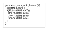
- FIG. 17 is a diagram illustrating an example syntax of a GDU header according to the embodiment.
- FIG. 18 is a diagram illustrating an example of setting the adjustment width of a non-standard width node according to the embodiment.
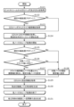
- FIG. 19 is a flowchart of encoding processing by the encoding device according to the embodiment.
- FIG. 20 is a flowchart of decoding processing by the decoding device according to the embodiment.
- FIG. 21 is a diagram illustrating an example of setting a non-standard width node according to the embodiment.
- FIG. 22 is a diagram illustrating an example of setting a non-standard width node according to the embodiment.
- FIG. 23 is a diagram illustrating an example of setting a non-standard width node according to the embodiment.
- FIG. 24 is a diagram illustrating an example of setting a non-standard width node according to the embodiment.
- FIG. 25 is a diagram illustrating an example of setting a non-standard width node according to the embodiment.
- FIG. 26 is a diagram illustrating an example of setting a non-standard width node according to the embodiment.
- FIG. 27 is a diagram illustrating an example of setting a non-standard width node according to the embodiment.
- FIG. 28 is a diagram showing the relationship between the node width and the width of the inclusive point coordinates according to the embodiment.
- FIG. 29 is a diagram illustrating an example of setting a non-standard width node according to the embodiment.
- FIG. 30 is a diagram illustrating an example of setting a non-standard width node according to the embodiment.
- FIG. 31 is a diagram illustrating an example syntax of GPS and GDU headers according to the embodiment.
- FIG. 32 is a diagram illustrating an example of slices and nodes according to the embodiment.
- FIG. 33 is a diagram illustrating an example of slices and nodes according to the embodiment.
- FIG. 34 is a diagram illustrating an example of processing when omitting according to the embodiment.
- FIG. 35 is a diagram illustrating an example syntax of GPS and GDU headers according to the embodiment.
- FIG. 36 is a flowchart of the omission determination process of the start end adjustment process according to the embodiment.
- FIG. 37 is a flowchart of the omission determination process of the end end adjustment process according to the embodiment.
- FIG. 38 is a flowchart of node position determination processing according to the embodiment.
- FIG. 39 is a flowchart of node width determination processing according to the embodiment.
- FIG. 40 is a flowchart of decoding processing according to the embodiment.
- FIG. 41 is a block diagram of a decoding device according to an embodiment.
- FIG. 42 is a flowchart of encoding processing according to the embodiment.
- FIG. 43 is a block diagram of a decoding device according to an embodiment.
- a three-dimensional data decoding method is a decoding method for decoding a plurality of three-dimensional points, and the method decodes a plurality of nodes having an octree structure and included in a first slice from a bitstream. obtain information for deriving the shape of a first node among the plurality of nodes from the bitstream, decode the first node according to the information, and determine the shape of the plurality of nodes. It is different from the prescribed shape of my other nodes. According to this, it is possible to set a node having a shape different from the prescribed shape. Therefore, variable nodes can be set according to the size of the slice or the distribution of the point group. Therefore, there is a possibility that encoding efficiency can be improved.
- the shape may be a rectangular parallelepiped, and may not be a cube.
- an edge of the first slice may coincide with an edge of any one of the plurality of nodes. According to this, even if the node end and the slice end do not match, the node end and the slice end can be made to match. Therefore, since it is possible to prevent a vertex from being generated at the end of the node, it is possible to suppress the generation of blank areas at slice boundaries. Therefore, the accuracy of the point cloud to be decoded can be improved.
- the information may indicate the size of the shape or the positions of both ends of the side of the first node.
- the decoding device can generate a node having a shape different from the prescribed shape using the information.
- the information may include adjustment information for adjusting the prescribed shape to the shape.
- the decoding device can generate a node having a shape different from the prescribed shape using the adjustment information. Furthermore, compared to the case where the absolute amount of position information is sent, there is a possibility that the amount of information can be made smaller.
- the decoding may be performed according to a compression method in which the plurality of three-dimensional points are approximated by a plane or a curved surface within the first node.
- the compression method may be a Triangle-Soup compression method.
- the shape may be determined to generate the plane or the curved surface within the first node. According to this, by setting a node having a shape different from the prescribed shape, a plane or a curved surface can be generated within the first node.
- the side of the shape may have an apex thereon, and the plane or curved surface may intersect the side at the apex. According to this, by setting a node having a shape different from the prescribed shape, a plane or a curved surface can be generated within the first node.
- the first node may be provided in contact with a second slice adjacent to the first slice.
- a node end and a slice end do not match, it is possible to prevent a vertex from being generated at the node end, so it is possible to suppress the generation of blank areas at slice boundaries.
- the slice boundary may separate the nodes. In that case, the first node cannot be encoded or decoded using the point cloud in the second slice adjacent to the first slice, so the reconstruction accuracy of the three-dimensional point cloud near the slice boundary may deteriorate. There is.
- the end of the first node can be made to coincide with the end of the first slice, for example.
- the end of the first node can be made to coincide with the end of the first slice, for example.
- the information is provided for each slice, and the information of the second slice has an 8-ary tree structure, and is used to derive the shape of the second node among the plurality of nodes included in the second slice. and the shape of the second node may be different from the prescribed shape. According to this, the shape of the node can be set for each slice.
- the size of the prescribed shape may be expressed as a power of two, and the size of the shape may be different from the size expressed as a power of two.
- the shape of the first node is defined by a first length along a first direction, a second length along a second direction, and a third length along a third direction.
- the first direction, the second direction, and the third direction are orthogonal to each other, and only the first length is the first length, the second length, and the third length. is different from the length of the prescribed shape of a node other than the first node, or the first length and the third length are different from the length of the prescribed shape of the nodes other than the first node, or 2 may differ from the length of the defined shape, respectively.
- the first node is closest to the origin of the first slice among the plurality of nodes in one of a first direction, a second direction, and a third direction;
- the second direction and the third direction may be orthogonal to each other. According to this, when the start position of the slice does not match the origin, for example, the start position of the node can be adjusted in accordance with the start position of the slice.
- the plurality of nodes may include a third node having a shape different from the prescribed shape, and the third node may be farthest from the origin in the one direction among the plurality of nodes. According to this, when the end position of a slice does not match the end position of a node, for example, the end position of a node can be adjusted in accordance with the end position of a slice.
- the bitstream may include the information, and if the starting position of the first slice coincides with the origin, the bitstream may not include the information. good. According to this, the occurrence of processing for adjusting the shape of the node can be reduced. Furthermore, transmission of information for deriving the shape of the node can be omitted. Therefore, it is possible to reduce the amount of processing and the amount of bitstream data.
- the bitstream includes the information, and the end position of the first slice does not match the end of the first node.
- the bitstream may not include the information. According to this, the occurrence of processing for adjusting the shape of the node can be reduced. Furthermore, transmission of information for deriving the shape of the node can be omitted. Therefore, it is possible to reduce the amount of processing and the amount of bitstream data.
- a three-dimensional data encoding method is an encoding method that encodes a plurality of three-dimensional points, has an octree structure, and encodes a plurality of nodes included in a first slice.
- information for deriving the shape of a first node among the plurality of nodes is stored in the bitstream, and the shape is different from other nodes among the plurality of nodes.
- the shape differs from the specified shape. According to this, it is possible to set a node having a shape different from the prescribed shape. Therefore, variable nodes can be set according to the size of the slice or the distribution of the point group. Therefore, there is a possibility that encoding efficiency can be improved.
- a decoding device is a decoding device that decodes a plurality of three-dimensional points, and includes a processor and a memory, and the processor uses the memory to decode a bitstream from a bitstream.
- an encoding device is an encoding device that encodes a plurality of three-dimensional points, and includes a processor and a memory, and the processor uses the memory to A bitstream is generated by encoding a plurality of nodes included in a first slice, and information for deriving the shape of a first node among the plurality of nodes is added to the bitstream. and the shape is different from the prescribed shape of other nodes among the plurality of nodes.
- the encoding device generates a bitstream by encoding three-dimensional data.
- the decoding device generates three-dimensional data by decoding the bitstream.
- the three-dimensional data is, for example, three-dimensional point group data (also referred to as point group data).
- a point cloud is a collection of three-dimensional points and indicates the three-dimensional shape of an object.
- the point cloud data includes position information and attribute information of a plurality of three-dimensional points.
- the position information indicates the three-dimensional position of each three-dimensional point.
- the position information may also be referred to as geometry information.
- position information is expressed in a rectangular coordinate system or a polar coordinate system.
- the attribute information indicates, for example, color information, reflectance, transmittance, infrared information, normal vector, or time information.
- One three-dimensional point may have a single attribute information, or may have multiple types of attribute information.
- the encoding device may also encode and decode attribute information.
- Tri-soap method The encoding device according to this embodiment encodes position information using a TriSoup (Triangle-Soup) method.
- the trisoap method is one of the methods for encoding position information of point cloud data, and is an irreversible compression method.
- the original point group to be processed is replaced with a set of triangles, and the point group is approximated on the plane.
- the original point group is replaced with vertex information within the node, and the vertices are connected to generate a triangle group.
- vertex information for generating triangles is stored in a bitstream and sent to the decoding device.
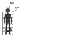
- FIG. 1 is a diagram showing an example of a group of original points. As shown in FIG. 1, a point group 102 of the object is included in the object space 101 and includes a plurality of points 103.
- the encoding device divides the original point group into an octree to a predetermined depth.
- octree division a target space is divided into eight nodes (subspaces), and 8-bit information (occupancy code) indicating whether a point group is included in each node is generated.
- the node including the point cloud is further divided into eight nodes, and 8-bit information indicating whether or not the point group is included in each of the eight nodes is generated. This process is repeated up to a predetermined hierarchy.
- 8-ary tree division is performed up to an intermediate layer, but is not performed on layers below that layer.
- Such an 8-ary tree up to an intermediate level is called a pruned 8-ary tree.
- FIG. 2 is a diagram showing an example of a pruned 8-ary tree. As shown in FIG. 2, the point cloud 102 is divided into a plurality of leaf nodes 104 (lowest layer nodes) of a pruned 8-ary tree.
- the encoding device performs the following processing on each leaf node 104 of the pruned 8-ary tree.
- leaf nodes are also simply referred to as nodes.
- the encoding device generates a vertex on the edge as a representative point of a point group close to the edge of the node. This vertex is called an edge vertex.
- edge vertex For example, edge vertices are generated for each of a plurality of edges (eg, four parallel sides).
- FIG. 3 is an example of a two-dimensional display of the leaf node 104, and is a diagram showing, for example, an xy plane viewed from the z direction shown in FIG. 1. As shown in FIG. 3, edge vertices 112 are generated on the edge based on points near the edge among the plurality of points 111 in the leaf node 104.
- the dotted line on the outer periphery of the leaf node 104 is an edge.
- the edge vertex 112 is generated at a position that is a weighted average of the positions of points within 1 distance from the edge (points included in the range 113 in FIG. 3).
- the unit of distance is, for example, the resolution of a point group, but is not limited thereto.
- this distance (threshold value) is 1 in this example, it may be other than 1 and may be variable.
- the encoding device also generates vertices inside the node based on the point group existing in the normal direction of the plane including the plurality of edge vertices. This vertex is called a centroid vertex.
- FIGS. 4 and 5 are diagrams for explaining the method of generating centroid vertices.
- the encoding device selects, for example, four points as representative points from a group of edge vertices. In the example shown in FIG. 4, edge vertices v1 to v4 are selected.
- the encoding device calculates an approximate plane 121 passing through the four points.
- the encoding device calculates the normal n of the approximate plane 121 and the average coordinate M of the four points.
- the encoding device converts the centroid vertex C into a weighted average coordinate of one or more points (for example, points included in the range 122 shown in FIG. 5) close to a half-line extending from the average coordinate M in the direction of the normal line n. generate.
- the encoding device entropy encodes vertex information, which is information on edge vertices and centroid vertices, and converts the encoded vertex information into a geometry data unit (hereinafter referred to as GDU) included in the bitstream. ).
- GDU geometry data unit
- the GDU includes information indicating a pruned 8-ary tree in addition to the vertex information.
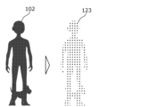
- FIG. 6 is a diagram showing an example of vertex information.
- the point group 102 is converted into vertex information 123, as shown in FIG.
- the decoding device decodes the GDU from the bitstream and obtains vertex information.
- the decoding device connects the vertices to generate a TriSoup-Surface, which is a group of triangles.
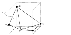
- FIG. 7 is a diagram showing an example of a trithorpe surface.
- four edge vertices v1 to v4 and a centroid vertex C are generated based on the vertex information.
- a triangle 131 (trisoap surface) having the centroid vertex C and two edge vertices as vertices is generated. For example, pairs of two edge vertices on two adjacent edges are each selected, and a triangle 131 having the selected pair and the centroid vertex as vertices is generated.
- FIG. 8 is a diagram for explaining the point cloud restoration process.
- the decoding device restores the position information of the point group 133 by generating points 132 at regular intervals on the surface of the triangle 131.
- FIG. 9 is a diagram showing an example where a point group extending in the vertical direction is divided into slices.
- FIG. 10 is a diagram showing an example of vertices generated in this case.
- the slice is divided from the bottom by nodes having a specified width.
- node 1 at the top of the slice includes a blank area.
- edge vertex v2 should be generated at the upper edge, but edge vertex v2 cannot be generated because there is no point group near the edge.
- the slice boundaries shown in FIGS. 9 and 10 are boundaries of bounding boxes of slices.
- FIG. 11 is a diagram showing an example of the trisoap surface that should originally be generated.
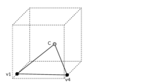
- FIG. 12 is a diagram showing an example of a trithorpe surface when no edge vertices are generated as shown in FIG. 10. As shown in FIG. 12, if edge vertices v2 and v3 are not generated on the upper edge, a trisoap surface is generated only with vertices v1 and v4 on the lower edge and the centroid vertex c. As a result, the trithorpe surface that should originally traverse the node is generated only at the bottom of the node.
- FIG. 13 is a diagram showing an example of the restored point group in this case. As shown in FIG. 13, since points are not restored in areas where there is no trisoap surface, holes are created across the restored point group, as in area 201 shown in FIG.
- the width of the node located at the edge of the bounding box of a slice is set to a width different from the specified width.
- FIG. 14 is a diagram showing an example of vertices generated in this case.
- FIG. 15 is a diagram showing an example of a trisoap surface in this case.
- a node 1 having an unspecified width is provided at the end of the slice.
- the blank space within the node 1 can be eliminated and the edge vertex v2 can be generated. Therefore, as shown in FIG. 15, it is possible to generate a tri-thorpe surface that traverses the inside of the node, thereby eliminating the generation of transverse holes in the restored point group.
- the encoding device stores, for example, information indicating the slice width in the GDU header as adjustment width information that is information for calculating the adjustment width of this non-standard width node.
- a non-specified width node is a node in which the length of a side along at least one of the length, width, and height is different from the specified length (specified width).
- the non-specified width node has a rectangular parallelepiped or cubic shape that is different from the cubic shape of the specified width.
- the adjustment width information is information for adjusting the specified length of the side of the node to an adjustment width of a side length different from the specified width (non-specified width).
- the adjustment width information may indicate the length of the adjustment width itself, may indicate the difference between the specified width and the adjustment width, or may indicate the ratio between the specified width and the adjustment width.
- the adjustment width (non-specified width) of a non-specified width node is expressed as min (slice width - node position, specified width).
- the non-specified width of a certain node is set to the minimum value between (slice width - node position) and the specified width.
- the node position is the position (coordinates) of the corner of the node that is closest to the origin, as shown in FIG.
- edge vertices can also be generated at the end nodes of the bounding box of the slice.
- the trisoap surface can be arranged without interruption, which eliminates the occurrence of holes in the restored point cloud.
- the point group included in the first slice is also included in the leaf node of the second slice.
- the first slice and the second slice have overlapping point groups.
- the point group is divided into slices by matching the boundary coordinates between the first slice and the second slice with the leaf node width. In other words, nodes with blank spaces due to slice division are not generated.
- Transmission information transmitted from the encoding device to the decoding device in order to implement the above method will be described below.
- transmission information is stored in a bitstream.
- FIG. 16 is a diagram showing an example of this transmission information.
- the GDU header included in the bitstream includes a non-standard width processing flag and slice width information.
- the non-standard width processing flag is information indicating whether or not to set the above-mentioned non-standard width node. For example, a value of 1 indicates that a non-standard width node is set, and a value of 0 indicates that a non-standard width node is not set.
- the slice width information indicates the slice width (the width of the bounding box of the slice).
- FIG. 17 is a diagram showing an example of the syntax of the GDU header (geometry_data_unit_header). As shown in FIG. 17, slice width information is stored in the GDU header only when the non-standard width processing flag has a value of 1 (true). Further, the slice width information includes, for example, information indicating the width of each slice in the x, y, and z axes.
- the slice width information is information for each slice, and here, the non-standard width processing flag and slice width information are stored in the GDU header, which is a header for each slice.
- non-standard width processing flag may be information indicating whether slice width information is included in the bitstream.
- the names of flags, information, etc. shown in this embodiment are merely examples, and any names can be used.
- these pieces of information may be common to a plurality of slices.
- these pieces of information may be stored in a header higher than the GDU header, such as SPS or GPS.
- SPS Sequence Parameter Set
- GPS Global System Parameter Set
- GPS is metadata (parameter set) related to encoding of position information. For example, GPS is metadata common to multiple frames.
- a flag indicating whether this information is stored in the upper header or for each slice may be stored in the SPS or GPS. In this case, the storage location of these pieces of information is switched based on the flag.
- these pieces of information are for processing specific to the tri-soap method, they may be stored in the bitstream only when the encoding method is the tri-soap method.
- FIG. 19 is a flowchart of encoding processing by the encoding device.
- the encoding device generates a pruned 8-ary tree, and stores 8-ary tree information indicating the pruned 8-ary tree in the GDU (S101). For example, the encoding device entropy encodes the octree information and stores the encoded octree information in the GDU.
- the encoding device performs the following steps S105 to S109 on each of the plurality of leaf nodes of the pruned octtree.
- the encoding device calculates the adjustment width from the slice width indicated by the slice width information and the node position of the target node, and adjusts the target node to the calculated adjustment width. (S107).
- the encoding device sets the width of the target node to the standard width ( S108).
- the encoding device generates edge vertices on the edges of the target node and generates centroid vertices inside the target node based on the point group distribution within the target node (S109). With the above, the loop processing for the target node is completed.
- the encoding device After the loop processing for all leaf nodes is completed, the encoding device entropy encodes the vertex information indicating the positions of the edge vertices and centroid vertices of the plurality of leaf nodes, and stores the encoded vertex information in the GDU. (S110).
- the encoding device generates a bitstream including the GDU header and GDU, and outputs the bitstream (S111). That is, the encoding device transmits the bitstream to the decoding device.
- FIG. 20 is a flowchart of the decoding process by the decoding device.
- the decoding device obtains the GDU header and GDU from the bitstream (S121).
- the decoding device obtains octree information from the GDU. For example, the decoding device acquires 8-ary tree information by entropy decoding the encoded 8-ary tree information included in the GDU. Next, the decoding device generates a group of leaf nodes of the pruned 8-ary tree using the 8-ary tree information (S124).
- the decoding device performs the following steps S125 to S130 on each of the plurality of leaf nodes of the pruned 8-ary tree.
- the decoding device calculates the adjustment width from the slice width indicated by the slice width information and the node position of the target node, and adjusts the target node to the calculated adjustment width. (S127).
- the decoding device sets the width of the target node to the specified width (S128). .
- the decoding device obtains vertex information indicating the positions of edge vertices and centroid vertices from the GDU (S129). For example, the decoding device acquires vertex information by entropy decoding encoded vertex information included in the GDU.
- the decoding device generates a triangle group by connecting a plurality of vertices indicated by the vertex information (S130). With the above, the loop processing for the target node is completed.
- the decoding device After completing the loop processing for all leaf nodes, the decoding device generates a decoded point group by generating points at regular intervals on the surfaces of multiple triangles (S131).
- FIGS. 21 to 24 are diagrams showing examples of setting non-standard width nodes.
- the position of the non-standard width node may be in the middle of the slice.
- the position of the non-standard width node may be at the beginning of the slice.
- a plurality of non-standard width nodes may be set.
- two non-standard width nodes may be set at both ends of the slice.
- two non-standard width nodes may be set at the end of the slice and at the middle of the slice.
- the sum of the widths of the plurality of non-standard width nodes only needs to be the above-mentioned adjustment width.
- non-standard width node information which is information for non-standard width nodes, that is stored in the bitstream.
- the non-specified width node information when the non-specified width node is placed at a location other than the end of the slice, the non-specified width node information includes the adjusted width information indicating the adjusted width and the insertion position of the non-specified width node. and insertion position information indicating the insertion position.
- the insertion position information indicates the bit string "4b0010”.
- the insertion position information indicates the bit string "4b1000”. Note that the plurality of bits in the bit string each correspond to a node, and the bit corresponding to the non-standard width node is set to 1, and the other bits are set to 0.
- the insertion position information may indicate information that specifies a non-standard width node.
- a serial number identifier
- the insertion position information may indicate a serial number of a non-standard width node.
- a serial number may be set for each axis within a slice. In this case, in the example shown in FIG. 21, serial numbers 1, 2, 3, and 4 are set in order from the left node, and the insertion position information indicates the value 3.
- the serial number may be a serial number for all nodes within a slice.
- the decoding device can use the insertion position information to determine whether the target node is a non-standard width node. Further, the adjustment width can be calculated using the same method as shown in FIG.
- the insertion position information indicates the individual insertion positions of the multiple non-standard width nodes.
- the insertion position information indicates the bit string "5b1001".
- the insertion position information indicates the bit string "5b10010". Note that here we have shown an example in which one bit string is used for one axis (x-axis in this example) (that is, an example in which a different bit string is used for each axis), but one bit string is used for all nodes in the slice. Two bit strings may be used.
- the adjustment width information indicates the adjustment width of each of the two non-standard width nodes. Specifically, the adjustment width information indicates a value 2, which is the adjustment width of the first non-standard width node, and a value 2, which is the adjustment width of the second non-standard width node.
- the adjustment width information may indicate the total adjustment width of two non-standard width nodes and the adjustment width of one non-standard width node.
- the decoding device can calculate the adjustment widths of the two non-standard width nodes from the adjustment width information.
- the adjustment width information of the last non-standard width node in a row of non-standard width nodes on one axis is omitted, a rule is determined in advance, and the decoding device , the adjustment widths of the two non-standard width nodes may be calculated from the adjustment width information.
- the non-standard width node information may be composed of individual information of all non-standard width nodes within a slice, instead of information for each axis.
- FIG. 25 is a diagram showing an example of setting the non-standard width node in this case.
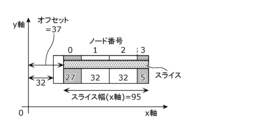
- the example shown in FIG. 25 is an example in which the node at the end of the slice is set to a non-standard width node.
- the non-standard width node information includes the amount of offset from the origin coordinates to the start position of the bounding box of the slice.
- the decoding device can calculate the adjustment width using this offset amount.
- the non-standard width node information includes information indicating the fractional node width, which is the adjusted width of the node at the end of the slice. The decoding device uses this information to set the adjustment width of the node at the edge of the slice to the fractional node width.
- FIG. 26 is a diagram showing an example of setting the non-standard width node in this case.
- the non-specified width may be a value larger than the specified width.
- the third node and the fourth node may be combined. That is, three nodes whose widths are 32, 32, and 36 from the left may be set.
- the node may become a cube.
- the position information of the corner of the node may be transmitted so that the size of the non-standard width node can be restored.
- the position information may be coordinate information of two corners in the direction of the non-standard width, or may be coordinate information of all eight corners.
- the encoding device may quantize the above-mentioned non-standard width node information for calculating the adjustment width, and transmit the quantized information to the decoding device.
- the decoding device may perform the above processing by dequantizing the quantized information and using the obtained non-standard width node information. In this case, a case may occur in which the width of the blank area within the non-standard width node does not become completely zero. On the other hand, by performing quantization, the amount of data to be transmitted can be reduced.
- the default size of the node is determined depending on the size of the bounding box to be octree encoded (bit depth of the original data) and the depth to which the octree division is to proceed. be done.
- This specified width is expressed, for example, as a power of two.
- a non-standard width node is a node in which the length of a side along at least one of the length, width, and height differs from the specified width, but the length in only one direction, or in only two directions.
- the length may be different from the specified width. That is, the non-standard width node may be a rectangular parallelepiped.
- edge vertices existing on four parallel edges of a node are found, but the number of edge vertices to be found is not limited to four.
- the number of edge vertices is not particularly limited as long as an approximate plane is obtained.
- the method of finding the centroid apex is not limited to the above method. As long as the decoding device can determine the plane of the triangle, the centroid vertices may be determined using other methods.
- the tri-soap method was used as the compression method, but the method of this embodiment is also effective for compression methods other than the tri-soap method.
- the method of this embodiment is a compression method that approximates a point group using a plane or curved surface within a node, and is effective for a compression method that requires edge vertices to generate the plane or curved surface. It is.
- the non-standard length of the side of the non-standard width node is determined, but it is not essential to determine the non-standard length. It is only necessary to find the shape of the non-standard width node; for example, the positions of the two ends of the side with the non-standard length may be found. That is, the position of the non-standard width node may be determined.
- the origin of the slice is an unspecified offset amount, and the starting position of the bounding box of the slice does not necessarily match the origin. Therefore, there may be a case where the point group of the slice after subtracting this offset amount is distributed away from the origin of the encoding coordinate system. That is, there are cases where the origin of the encoded coordinate system and the origin of the bounding box of the slice are different. Furthermore, in this case, the boundaries of the bounding box of the slice may not coincide with the boundaries of the leaf nodes. In this case, it is necessary to generate non-standard width nodes on both the side of the bounding box of the slice on the origin side and the side of the bounding box on the side far from the origin.
- the encoding device uses the slice position, which is the start coordinate of the bounding box of the slice, and the width of the bounding box as information for the decoding device to calculate the node position and node width (adjusted width) of these non-standard width nodes.
- the slice width is transmitted to the decoding device.
- FIG. 27 is a diagram showing an example of setting the non-standard width node in this case.
- the encoded coordinate system is expressed one-dimensionally.
- the shaded area is an area (slice) in which the point group is distributed.
- the origin shown in FIG. 27 is the origin of the encoding coordinate system.
- the adjusted node position newNodePos and the adjusted node width newNodeWidth are calculated as follows. .
- the node position is adjusted to A if nodePos ⁇ A, otherwise it is not adjusted. That is, the node position of node 1, which is the leading node, is changed from P1 to A, and the node positions of the other nodes are not changed.
- the node widths of other nodes are set to W.
- the decoding device obtains A and B from the transmission information, and uses the above formula from the initial node position and initial node width of each node. are used to calculate the adjusted node positions and adjusted node widths of nodes 1 and 2.
- the position of the non-standard width node may be located at the beginning of the slice, in the middle of the slice, at both ends of the slice, or at multiple positions.
- the total node width may be the above-mentioned adjustment width.
- the following can be used as the calculation method and the non-standard width node information, which is information for non-standard width nodes, that is stored in the bitstream.
- FIG. 29 is a diagram showing an example of setting a non-standard width node.
- the encoding device can calculate the adjusted position and adjustment width of node 1 on the origin side.
- the decoding device can calculate the adjustment width of the node 2 on the far side from the origin.
- the non-standard width node information also includes information specifying a non-standard width node and the information for the specified node.
- Information indicating the adjustment position and adjustment width of the node may be included.
- the information specifying the non-standard width node indicates, for example, a serial number assigned to the node.
- FIG. 30 is a diagram showing an example of setting the non-standard width node in this case.
- 0 to 3 are assigned as node numbers, which are serial numbers of nodes.
- FIG. 29 a method for determining a non-standard width node and calculating its position and width has been explained, but it is also possible to use any of the methods explained in FIGS. Good too.
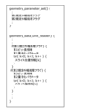
- FIG. 31 is a diagram illustrating an example of the syntax of GPS (geometry_parameter_set) and GDU header.
- the GPS includes a first non-standard width processing flag and a second non-standard width processing flag.
- the first non-standard width processing flag is information indicating whether or not to perform the above-described node position and node width adjustment on the node located at the end of the slice closer to the origin. For example, a value of 1 indicates that the adjustment is performed, and a value of 0 indicates that the adjustment is not performed.
- the second non-standard width processing flag is information indicating whether or not to perform the above-described node width adjustment on the node located at the slice end on the side far from the origin. For example, a value of 1 indicates that the adjustment is performed, and a value of 0 indicates that the adjustment is not performed.
- the GDU header includes first bit length information, a first quantization parameter, and slice position information.
- the slice position information indicates the slice position, which is the position (coordinates) of the bounding box of the slice, and for example, indicates the three-dimensional coordinates (x, y, z coordinates) of the corner of the bounding box of the slice that is closest to the origin. .
- the first bit length information indicates the bit length of slice position information.
- the first quantization parameter indicates a quantization parameter (quantization value) used for quantizing slice position information.
- the GDU header includes second bit length information, a second quantization parameter, and slice width information.
- the slice width information indicates the slice width, which is the width of the bounding box of the slice.
- the slice width information indicates the width of the bounding box in each of the x, y, and z directions.
- the second bit length information indicates the bit length of the slice width.
- the second quantization parameter indicates a quantization parameter used for quantizing slice width information.
- the slice position is represented by slice position information ⁇ first quantization parameter
- the slice width is represented by slice width information ⁇ second quantization parameter.
- these pieces of information are stored for each slice, but if these pieces of information are common to multiple slices, these pieces of information are stored above the GDU header such as SPS or GPS. may be stored in the header of Further, a flag indicating whether this information is stored in the upper header or for each slice may be stored in the SPS or GPS. In this case, the storage location of these pieces of information is switched based on the flag. Furthermore, this information may be provided individually for each axis of x, y, and z.
- the encoding device does not need to transmit the first non-standard width processing flag and the second non-standard width processing flag shown in FIG. 31.
- the slice position information and the slice width information are numerical values in the encoded coordinate system, they may be determined to be positive values.
- the encoding device performs this omission determination and transmits information indicating the determination result to the decoding device.
- a dedicated flag may be used for this transmission, or the first bit length information and second bit length information described above may be used. Specifically, when the first bit length information indicates 0, it means that transmission of slice position information is omitted, and when the second bit length information indicates 0, it means that transmission of slice width information is omitted. means. This allows the amount of header data to be suppressed and the processing time for encoding processing to be shortened.
- FIG. 32 is a diagram showing an example of a slice and a node when the starting end of the slice coincides with the origin. In this case, there is no need to adjust the starting end.
- FIG. 33 is a diagram showing an example of a slice and a node in a case where the start end of the slice coincides with the origin and the end end of the slice coincides with the end end of the node. In this case, adjustment processing is not required for both the start end and the end end.
- FIG. 34 is a diagram showing an example of processing (syntax) when the above omission is performed.
- slice_bb_pos_bits shown in the figure is first bit length information indicating the bit length of slice position information.
- slice_bb_width_bits is second bit length information indicating the bit length of slice width information.
- A is the slice position
- B is the slice width
- nodePos is the node position (node position before adjustment)
- nodeWidth is the node width (node width before adjustment)
- newNodeWidth is the node after adjustment.
- W is the specified width of the node.
- the adjustment process is performed only when the bit length of the slice position information is a value greater than 0, so the processing time of the encoding process can be reduced. Furthermore, if the start end of a slice coincides with the origin or the end end coincidentally coincides with the end end of a node, the amount of data in the header can be reduced.
- FIG. 35 is a diagram showing an example of the syntax of the GPS and GDU headers in this case.
- the syntax shown in FIG. 35 differs from the syntax shown in FIG. 31 in that the first quantization parameter and slice position information are stored in the GDU header only when the first bit length information is greater than 0. and a condition that the second quantization parameter and slice width information are stored in the GDU header only when the second bit length information is greater than 0 are added.
- the amount of data in the header can be reduced when the start end of the slice matches the origin or the end end matches the end end of the node.
- FIG. 36 is a flowchart of the omission determination process of the start end adjustment process (slice position transmission).
- the encoding device determines whether the start position of the slice (coordinates of the start end of the bounding box of the slice) matches the origin (S201).
- the encoding device transmits slice position information (S203). That is, the encoding device stores slice_bb_pos_bits set to a value greater than 0 and slice position information in the bitstream.
- FIG. 37 is a flowchart of the omission determination process of the end end adjustment process (slice width transmission).
- the encoding device determines whether the end position of the slice (coordinates of the end of the bounding box of the slice) matches the end of the node (S211).
- the encoding device transmits slice width information (S213). That is, the encoding device stores slice_bb_width_bits set to a value greater than 0 and slice width information in the bitstream.
- FIG. 38 is a flowchart of the node position determination process. For example, the process shown in FIG. 38 is performed for each node.
- the encoding device determines whether the first bit length information (slice_bb_pos_bits) is greater than 0 (S221).
- the encoding device determines whether the node position (nodePos) of the target node is smaller than the slice position (S222).
- the encoding device sets the slice position as the adjusted node position (S223).
- the encoding device does not change (adjust) the node position (S224).
- FIG. 39 is a flowchart of the node width determination process. For example, the process shown in FIG. 39 is performed for each node.
- the encoding device determines whether the first bit length information (slice_bb_pos_bits) is greater than 0 (S231).
- the encoding device determines whether the node position (nodePos) of the target node is smaller than the slice position (S232).
- the encoding device sets the specified width (W) - (slice position (A) - node position (nodePos)) as the adjusted node width (nodeWidth). (S233).
- the encoding device determines whether the second bit length information (slice_bb_width_bits) is greater than 0 (S234).
- the encoding device converts min(slice position (A) + slice width (B) - node position (nodePos) + 1, specified width (W)) into a node. It is set as the width (nodeWidth) (S235).
- the encoding device does not change the node width (nodeWidth) (S236). That is, the encoding device sets the node width to the specified width (W).
- the encoding device determines whether the second bit length information (slice_bb_width_bits) is greater than 0 (S237). Note that the case where the first bit length information is 0 (No in S231) means that the slice position information is not transmitted, and the start end of the slice coincides with the origin.
- the encoding device sets min(slice width (B) - node position (nodePos) + 1, specified width (W)) as the node width (nodeWidth). (S238).
- the encoding device does not change the node width (nodeWidth) (S236). That is, the encoding device sets the node width to the specified width (W).
- the decoding device (three-dimensional data decoding device) according to the embodiment performs the processing shown in FIG. 40.
- the decoding device is a decoding device that decodes a plurality of three-dimensional points.
- the decoding device obtains a plurality of nodes having an octree structure and included in the first slice from the bitstream (S301), and derives the shape of the first node among the plurality of nodes from the bitstream. (S302), the first node is decoded according to the information (S303), and the shape of the first node is different from the prescribed shape of other nodes among the plurality of nodes. According to this, it is possible to set a node having a shape different from the prescribed shape. Therefore, variable nodes can be set according to the size of the slice or the distribution of the point group. Therefore, there is a possibility that encoding efficiency can be improved.
- the shape of the first node is a rectangular parallelepiped, not a cube.
- the edge of the first slice coincides with the edge of any one of the plurality of nodes. According to this, even if the node end and the slice end do not match, the node end and the slice end can be made to match. Therefore, since it is possible to prevent a vertex from being generated at the end of the node, it is possible to suppress the generation of blank areas at slice boundaries. Therefore, the accuracy of the point cloud to be decoded can be improved.
- the size of the shape of the first node is different from the prescribed size of the prescribed shape.
- the length of the side of the shape of the first node is different from the prescribed length (eg, prescribed width) of the side of the prescribed shape.
- the information for deriving the shape of the first node indicates the size of the shape of the first node or the positions of both ends of the sides of the first node. According to this, the decoding device can generate a node having a shape different from the prescribed shape using the information.
- the information for deriving the shape of the first node includes adjustment information (for example, slice width information or slice position information) for adjusting the prescribed shape to the shape of the first node.
- the decoding device can generate a node having a shape different from the prescribed shape using the adjustment information. Furthermore, compared to the case where the absolute amount of position information is sent, there is a possibility that the amount of information can be made smaller.
- the decoding of the first node is performed according to a compression method in which a plurality of three-dimensional points are approximated by a plane or curved surface within the first node.
- the compression method is the Triangle-Soup compression method.
- the shape of the first node is determined in order to generate a plane or a curved surface within the first node. According to this, by setting a node having a shape different from the prescribed shape, a plane or a curved surface can be generated within the first node.
- the edge of the shape of the first node has a vertex on it, and the plane or curved surface intersects the edge at the vertex.
- a plane or a curved surface can be generated within the first node.
- the plurality of three-dimensional points include a first three-dimensional point located near the vertex.
- the first node is provided in contact with a second slice adjacent to the first slice.
- a node end and a slice end do not match, it is possible to prevent a vertex from being generated at the node end, so it is possible to suppress the generation of blank areas at slice boundaries.
- the slice boundary may separate the nodes. In that case, the first node cannot be encoded or decoded using the point cloud in the second slice adjacent to the first slice, so the accuracy of restoring the three-dimensional point cloud near the slice boundary may deteriorate. There is.
- the end of the first node can be made to coincide with the end of the first slice, for example.
- the end of the first node can be made to coincide with the end of the first slice, for example.
- information for deriving the shape of the first node is provided for each slice, and information for the second slice has an 8-ary tree structure, and information for deriving the shape of the first node is provided for each slice. is used to derive the shape of the second node, and the shape of the second node is different from the prescribed shape. According to this, the shape of the node can be set for each slice.
- the size of the prescribed shape is expressed as a power of two
- the size of the first node shape is different from the size expressed as a power of two.
- the shape of the first node is defined by a first length along a first direction, a second length along a second direction, and a third length along a third direction;
- the first direction, second direction, and third direction are orthogonal to each other, and only the first length among the first length, second length, and third length defines a node other than the first node.
- the length is different from the length of the shape, or only the first length and the second length among the first length, the second length and the third length are different from the length of the prescribed shape.
- the first node is closest to the origin of the first slice among the plurality of nodes in one of the first direction, the second direction, and the third direction;
- the third directions are orthogonal to each other. According to this, when the start position of the slice does not match the origin, for example, the start position of the node can be adjusted in accordance with the start position of the slice.
- the origin is a position of a slice, a node, a three-dimensional point, or a reference position for defining a shape.
- the plurality of nodes include a third node having a shape different from the prescribed shape, and the third node is the farthest from the origin in one direction among the plurality of nodes. According to this, when the end position of a slice does not match the end position of a node, for example, the end position of a node can be adjusted in accordance with the end position of a slice.
- the bitstream contains information for deriving the shape of the first node
- the bitstream contains the information for deriving the shape of the first node. It does not contain information for deriving the shape of the node. According to this, the occurrence of processing for adjusting the shape of the node can be reduced. Furthermore, transmission of information for deriving the shape of the node can be omitted. Therefore, it is possible to reduce the amount of processing and the amount of bitstream data.
- start position (starting end) of a slice is the position of the end of the slice closer to the origin
- end position (end end) of the slice is the position of the end of the slice farther from the origin.
- starting position (starting edge) of a node is the position of the edge of the node on the side closer to the origin
- ending position (end edge) of a node is the position of the edge of the node on the side far from the origin.
- the bitstream includes information for deriving the shape of the first node, and the ending position of the first slice does not match the ending edge of the first node.
- the bitstream does not contain information for deriving the shape of the first node. According to this, the occurrence of processing for adjusting the shape of the node can be reduced. Furthermore, transmission of information for deriving the shape of the node can be omitted. Therefore, it is possible to reduce the amount of processing and the amount of bitstream data.
- FIG. 41 is a block diagram of the decoding device 10.
- the decoding device 10 includes a processor 11 and a memory 12, and the processor 11 uses the memory 12 to perform the above processing.
- the encoding device (three-dimensional data encoding device) according to the embodiment performs the processing shown in FIG. 42.
- the encoding device is an encoding device that encodes a plurality of three-dimensional points.
- the encoding device has an octree structure, generates a bitstream by encoding multiple nodes included in the first slice (S311), and derives the shape of the first node among the multiple nodes.
- information for the first node is stored in the bitstream (S312), and the shape of the first node is different from the prescribed shape of other nodes among the plurality of nodes.
- the encoding device may perform the same processing as the decoding device described above.
- FIG. 43 is a block diagram of the encoding device 20.
- the encoding device 20 includes a processor 21 and a memory 22, and the processor 21 uses the memory 22 to perform the above processing.
- the present disclosure is limited to this embodiment. It is not something that will be done.
- each processing unit included in the encoding device, decoding device, etc. is typically realized as an LSI, which is an integrated circuit. These may be integrated into one chip individually, or may be integrated into one chip including some or all of them.
- circuit integration is not limited to LSI, and may be realized using a dedicated circuit or a general-purpose processor.
- An FPGA Field Programmable Gate Array
- a reconfigurable processor that can reconfigure the connections and settings of circuit cells inside the LSI may be used.
- each component may be configured with dedicated hardware, or may be realized by executing a software program suitable for each component.
- Each component may be realized by a program execution unit such as a CPU or a processor reading and executing a software program recorded on a recording medium such as a hard disk or a semiconductor memory.
- the present disclosure also describes an encoding method (three-dimensional data encoding method) or a decoding method (three-dimensional data decoding method), etc.
- the present disclosure may be implemented as a program that executes the encoding method or decoding method on a computer, processor, or device. Further, the present disclosure may be implemented as a bitstream generated by the above encoding method. Further, the present disclosure may be realized as a recording medium on which the program or the bitstream is recorded. For example, the present disclosure may be realized as a non-transitory computer-readable recording medium on which the program or the bitstream is recorded.
- the present disclosure can be applied to encoding devices and decoding devices.
Landscapes
- Engineering & Computer Science (AREA)
- Multimedia (AREA)
- Physics & Mathematics (AREA)
- General Physics & Mathematics (AREA)
- Theoretical Computer Science (AREA)
- Signal Processing (AREA)
- Compression Or Coding Systems Of Tv Signals (AREA)
- Compression, Expansion, Code Conversion, And Decoders (AREA)
Abstract
Description
以下、本実施の形態に係る符号化装置(三次元データ符号化装置)及び復号装置(三次元データ復号装置)について説明する。符号化装置は、三次元データを符号化することでビットストリームを生成する。復号装置は、当該ビットストリームを復号することで三次元データを生成する。
本実施の形態に係る符号化装置は、トライソープ(TriSoup:Triangle-Soup)方式を用いて位置情報を符号化する。
以下、点群を複数のスライスに分割し、且つ、トライソープ方式を用いて符号化する場合について説明する。このような場合において、スライス幅がリーフノード幅の整数倍に一致しない場合、スライス境界で点が復元されない場合がある。具体的には、隣接する第1スライス及び第2スライスにまたがって点群が存在する場合、第1スライスに属するリーフノードであって第1スライスと第2スライスにまたがるリーフノードは、第2スライスに含まれる点群を含まないため、ノード内部に空白領域が発生するという問題がある。
以下、上記方式を実現するために、符号化装置から復号装置への送信される伝送情報について説明する。例えば、伝送情報は、ビットストリームに格納される。
以下、符号化装置及び復号装置における処理の流れを説明する。図19は、符号化装置による符号化処理のフローチャートである。
上記説明では、規定外幅ノードが、スライスの末尾(図18の右端)に生成される例を述べたが、規定外幅ノードが生成される位置はこれに限らない。図21~図24は、規定外幅ノードの設定例を示す図である。
図25において、スライスのバウンディングボックスの開始位置が原点と一致しない場合について説明した。以下、この場合の詳細について説明する。
newNodeWidth=(nodePos<A)?(W-(A-nodePos)):min(A+B-nodePos+1,W)
上記説明では、符号化対象の点群について常にスライス幅情報及びスライス位置情報をヘッダに格納し、全スライスの全ノードに対してノードの位置と幅を再計算する必要がある。実際には符号化対象のスライスの開始端が原点に一致、又はスライスの終了端がたまたまノードの終了端に一致している場合がある。この場合は、スライスの開始端のノード又は終了端のノードに対してノード位置又はノード幅の調整処理を行う必要が無いので、この調整処理のための情報の伝送と、ノード位置及びノード幅の再計算処理を省略できる。
以上のように、実施の形態に係る復号装置(三次元データ復号装置)は、図40に示す処理を行う。復号装置は、複数の三次元点を復号する復号装置である。復号装置は、ビットストリームから、8分木構造を有し、第1スライスに含まれる複数のノードを取得し(S301)、ビットストリームから、複数のノードのうちの第1ノードの形状を導出するための情報を取得し(S302)、第1ノードを情報に従い復号し(S303)、第1ノードの形状は、複数のノードのうちの他のノードの規定形状と異なる。これによれば、規定形状とは異なる形状のノードを設定できる。よって、スライスの大きさ又は点群の分布状況に合わせて可変のノードを設定できる。よって、符号化効率を向上できる可能性がある。
11、21 プロセッサ
12、22 メモリ
20 符号化装置
101 対象空間
102、133 点群
103、111、132 点
104 リーフノード
112 エッジ頂点
113、122 範囲
121 近似平面
123 頂点情報
131 三角形
201 領域
Claims (20)
- 複数の三次元点を復号する復号方法であって、
ビットストリームから、8分木構造を有し、第1スライスに含まれる複数のノードを取得し、
前記ビットストリームから、前記複数のノードのうちの第1ノードの形状を導出するための情報を取得し、
前記第1ノードを前記情報に従い復号し、
前記形状は、前記複数のノードのうちの他のノードの規定形状と異なる
復号方法。 - 前記形状は直方体形状であり、立方体形状ではない
請求項1記載の復号方法。 - 前記第1スライスの端は、前記複数のノードのうちのいずれかのノードの端と一致している
請求項1記載の復号方法。 - 前記情報は、前記形状のサイズ、又は、前記第1ノードの辺の両端の位置、を示す
請求項1記載の復号方法。 - 前記情報は、前記規定形状を前記形状に調整するための調整情報を含む
請求項1記載の復号方法。 - 前記復号は、前記複数の三次元点が前記第1ノード内の平面又は曲面で近似される圧縮方式に従い実行される
請求項1記載の復号方法。 - 前記圧縮方式は、Triangle-Soup圧縮方式である
請求項6記載の復号方法。 - 前記平面又は前記曲面を前記第1ノード内に生成するために前記形状が決定される
請求項6記載の復号方法。 - 前記形状の辺はその上に頂点を持ち、
前記平面または前記曲面は、前記頂点で前記辺と交差する
請求項8記載の復号方法。 - 前記第1ノードは、前記第1スライスに隣接する第2スライスと接して設けられる
請求項1記載の復号方法。 - 前記情報はスライスごとに設けられ、
前記第2スライスの前記情報は、8分木構造を有し、前記第2スライスに含まれる複数のノードのうちの第2ノードの形状を導出するために使用され、
前記第2ノードの形状は前記規定形状と異なる
請求項10記載の復号方法。 - 前記規定形状のサイズは2のべき乗で表され、前記形状のサイズは2のべき乗で表されるサイズとは異なる
請求項1記載の復号方法。 - 前記第1ノードの前記形状は、第1方向に沿った第1の長さ、第2方向に沿った第2の長さ、および第3方向に沿った第3の長さによって定義され、前記第1方向、前記第2方向、および前記第3方向は互いに直交し、
前記第1の長さ、前記第2の長さ及び前記第3の長さのうち前記第1の長さだけが前記第1ノード以外のノードの前記規定形状の長さと異なる、又は、前記第1の長さ、前記第2の長さ及び前記第3の長さのうち前記第1の長さ及び前記第2の長さだけが、それぞれ前記規定形状の長さと異なる
請求項1記載の復号方法。 - 前記第1ノードは、第1方向、第2方向及び第3方向のうちの一つの方向において、前記複数のノードのうちで前記第1スライスの原点に最も近く、前記第1方向、前記第2方向、および前記第3方向は互いに直交する
請求項1記載の復号方法。 - 前記複数のノードは、前記規定形状とは異なる形状を持つ第3ノードを含み、
前記第3ノードは、前記複数のノードのうち、前記一つの方向において前記原点から最も遠い
請求項14記載の復号方法。 - 前記第1スライスの開始位置が原点と一致しない場合、前記ビットストリームは前記情報を含み、
前記第1スライスの開始位置が原点と一致する場合、前記ビットストリームは前記情報を含まない、
請求項1記載の復号方法。 - 前記第1スライスの終了位置が前記第1ノードの終了端と一致しない場合、前記ビットストリームは、前記情報を含み、
前記第1スライスの終了位置が前記第1ノードの終了端と一致する場合、前記ビットストリームは前記情報を含まない、
請求項1記載の復号方法。 - 複数の三次元点を符号化する符号化方法であって、
8分木構造を有し、第1スライスに含まれる複数のノードを符号化することでビットストリームを生成し、
前記複数のノードのうちの第1ノードの形状を導出するための情報を前記ビットストリームに格納し、
前記形状は、前記複数のノードのうちの他のノードの規定形状と異なる
符号化方法。 - 複数の三次元点を復号する復号装置であって、
プロセッサと、
メモリと、を備え、
前記プロセッサは、前記メモリを用いて、
ビットストリームから、8分木構造を有し、第1スライスに含まれる複数のノードを取得し、
前記ビットストリームから、前記複数のノードのうちの第1ノードの形状を導出するための情報を取得し、
前記第1ノードを前記情報に従い復号し、
前記形状は、前記複数のノードのうちの他のノードの規定形状と異なる
復号装置。 - 複数の三次元点を符号化する符号化装置であって、
プロセッサと、
メモリと、を備え、
前記プロセッサは、前記メモリを用いて、
8分木構造を有し、第1スライスに含まれる複数のノードを符号化することでビットストリームを生成し、
前記複数のノードのうちの第1ノードの形状を導出するための情報を前記ビットストリームに格納し、
前記形状は、前記複数のノードのうちの他のノードの規定形状と異なる
符号化装置。
Priority Applications (6)
| Application Number | Priority Date | Filing Date | Title |
|---|---|---|---|
| JP2024542643A JPWO2024042909A1 (ja) | 2022-08-26 | 2023-07-14 | |
| CN202380060194.1A CN119731699A (zh) | 2022-08-26 | 2023-07-14 | 解码方法、编码方法、解码装置及编码装置 |
| KR1020257005085A KR20250056900A (ko) | 2022-08-26 | 2023-07-14 | 복호 방법, 부호화 방법, 복호 장치 및 부호화 장치 |
| EP23857025.3A EP4579597A4 (en) | 2022-08-26 | 2023-07-14 | DECODING METHOD, CODING METHOD, DECODING DEVICE AND CODING DEVICE |
| MX2025001645A MX2025001645A (es) | 2022-08-26 | 2025-02-10 | Metodo de decodificacion, metodo de codificacion, dispositivo de decodificacion y dispositivo de codificacion |
| US19/056,107 US20250191232A1 (en) | 2022-08-26 | 2025-02-18 | Decoding method, encoding method, decoding device, and encoding device |
Applications Claiming Priority (6)
| Application Number | Priority Date | Filing Date | Title |
|---|---|---|---|
| US202263401309P | 2022-08-26 | 2022-08-26 | |
| US63/401,309 | 2022-08-26 | ||
| US202263426137P | 2022-11-17 | 2022-11-17 | |
| US63/426,137 | 2022-11-17 | ||
| US202263435635P | 2022-12-28 | 2022-12-28 | |
| US63/435,635 | 2022-12-28 |
Related Child Applications (1)
| Application Number | Title | Priority Date | Filing Date |
|---|---|---|---|
| US19/056,107 Continuation US20250191232A1 (en) | 2022-08-26 | 2025-02-18 | Decoding method, encoding method, decoding device, and encoding device |
Publications (1)
| Publication Number | Publication Date |
|---|---|
| WO2024042909A1 true WO2024042909A1 (ja) | 2024-02-29 |
Family
ID=90013068
Family Applications (1)
| Application Number | Title | Priority Date | Filing Date |
|---|---|---|---|
| PCT/JP2023/025991 Ceased WO2024042909A1 (ja) | 2022-08-26 | 2023-07-14 | 復号方法、符号化方法、復号装置及び符号化装置 |
Country Status (7)
| Country | Link |
|---|---|
| US (1) | US20250191232A1 (ja) |
| EP (1) | EP4579597A4 (ja) |
| JP (1) | JPWO2024042909A1 (ja) |
| KR (1) | KR20250056900A (ja) |
| CN (1) | CN119731699A (ja) |
| MX (1) | MX2025001645A (ja) |
| WO (1) | WO2024042909A1 (ja) |
Cited By (2)
| Publication number | Priority date | Publication date | Assignee | Title |
|---|---|---|---|---|
| US20240214600A1 (en) * | 2022-12-22 | 2024-06-27 | Comcast Cable Communications, Llc | Motion Compensation based Neighborhood Configuration for TriSoup Centroid Information |
| WO2025216171A1 (ja) * | 2024-04-11 | 2025-10-16 | パナソニック インテレクチュアル プロパティ コーポレーション オブ アメリカ | 符号化方法、復号方法、符号化装置及び復号装置 |
Citations (5)
| Publication number | Priority date | Publication date | Assignee | Title |
|---|---|---|---|---|
| WO2014020663A1 (ja) | 2012-07-30 | 2014-02-06 | 三菱電機株式会社 | 地図表示装置 |
| US20210049828A1 (en) * | 2019-08-14 | 2021-02-18 | Lg Electronics Inc. | Apparatus for transmitting point cloud data, a method for transmitting point cloud data, an apparatus for receiving point cloud data and a method for receiving point cloud data |
| US20210321139A1 (en) * | 2020-04-07 | 2021-10-14 | Qualcomm Incorporated | High-level syntax design for geometry-based point cloud compression |
| WO2021262559A1 (en) * | 2020-06-23 | 2021-12-30 | Sony Group Corporation | Trisoup node size per slice |
| JP2022521680A (ja) * | 2019-06-26 | 2022-04-12 | テンセント・アメリカ・エルエルシー | ポイントクラウドのジオメトリ復号及び符号化のための暗示的な四分木又は二分木ジオメトリ分割 |
Family Cites Families (3)
| Publication number | Priority date | Publication date | Assignee | Title |
|---|---|---|---|---|
| US11172224B2 (en) * | 2019-09-03 | 2021-11-09 | Tencent America LLC | Techniques and apparatus for generalized Trisoup geometry coding |
| CN114981842B (zh) * | 2020-01-09 | 2025-08-19 | 苹果公司 | 点云的树内几何量化 |
| US11514612B2 (en) * | 2020-04-02 | 2022-11-29 | Tencent America LLC | Method and apparatus for point cloud coding |
-
2023
- 2023-07-14 WO PCT/JP2023/025991 patent/WO2024042909A1/ja not_active Ceased
- 2023-07-14 CN CN202380060194.1A patent/CN119731699A/zh active Pending
- 2023-07-14 JP JP2024542643A patent/JPWO2024042909A1/ja active Pending
- 2023-07-14 EP EP23857025.3A patent/EP4579597A4/en active Pending
- 2023-07-14 KR KR1020257005085A patent/KR20250056900A/ko active Pending
-
2025
- 2025-02-10 MX MX2025001645A patent/MX2025001645A/es unknown
- 2025-02-18 US US19/056,107 patent/US20250191232A1/en active Pending
Patent Citations (5)
| Publication number | Priority date | Publication date | Assignee | Title |
|---|---|---|---|---|
| WO2014020663A1 (ja) | 2012-07-30 | 2014-02-06 | 三菱電機株式会社 | 地図表示装置 |
| JP2022521680A (ja) * | 2019-06-26 | 2022-04-12 | テンセント・アメリカ・エルエルシー | ポイントクラウドのジオメトリ復号及び符号化のための暗示的な四分木又は二分木ジオメトリ分割 |
| US20210049828A1 (en) * | 2019-08-14 | 2021-02-18 | Lg Electronics Inc. | Apparatus for transmitting point cloud data, a method for transmitting point cloud data, an apparatus for receiving point cloud data and a method for receiving point cloud data |
| US20210321139A1 (en) * | 2020-04-07 | 2021-10-14 | Qualcomm Incorporated | High-level syntax design for geometry-based point cloud compression |
| WO2021262559A1 (en) * | 2020-06-23 | 2021-12-30 | Sony Group Corporation | Trisoup node size per slice |
Non-Patent Citations (1)
| Title |
|---|
| See also references of EP4579597A4 |
Cited By (2)
| Publication number | Priority date | Publication date | Assignee | Title |
|---|---|---|---|---|
| US20240214600A1 (en) * | 2022-12-22 | 2024-06-27 | Comcast Cable Communications, Llc | Motion Compensation based Neighborhood Configuration for TriSoup Centroid Information |
| WO2025216171A1 (ja) * | 2024-04-11 | 2025-10-16 | パナソニック インテレクチュアル プロパティ コーポレーション オブ アメリカ | 符号化方法、復号方法、符号化装置及び復号装置 |
Also Published As
| Publication number | Publication date |
|---|---|
| KR20250056900A (ko) | 2025-04-28 |
| US20250191232A1 (en) | 2025-06-12 |
| MX2025001645A (es) | 2025-03-07 |
| CN119731699A (zh) | 2025-03-28 |
| EP4579597A4 (en) | 2025-12-17 |
| JPWO2024042909A1 (ja) | 2024-02-29 |
| EP4579597A1 (en) | 2025-07-02 |
Similar Documents
| Publication | Publication Date | Title |
|---|---|---|
| CN113615181B (zh) | 用于点云编解码的方法、装置 | |
| WO2024042909A1 (ja) | 復号方法、符号化方法、復号装置及び符号化装置 | |
| US12165370B2 (en) | Context determination for planar mode in octree-based point cloud coding | |
| JP7678138B2 (ja) | ポイントクラウドデータ送信装置、ポイントクラウドデータ送信方法、ポイントクラウドデータ受信装置及びポイントクラウドデータ受信方法 | |
| BR112021002464A2 (pt) | método de codificação de dados tridimensionais, método de decodificação de dados tridimensionais, dispositivo de codificação de dados tridimensionais, e dispositivo de decodificação de dados tridimensionais | |
| JP7723199B2 (ja) | 符号化装置、復号装置、符号化方法及び復号方法 | |
| US20250371744A1 (en) | Encoding method, decoding method, encoding device, and decoding device | |
| CN117223287A (zh) | 点云处理方法及装置、编码器、解码器、可读存储介质 | |
| CN119366187A (zh) | 编解码方法、码流、编码器、解码器以及存储介质 | |
| CN118613832A (zh) | 三维数据编码方法、三维数据解码方法、三维数据编码装置及三维数据解码装置 | |
| KR20250076567A (ko) | 포인트 클라우드 데이터 송신 장치, 포인트 클라우드 데이터 송신 방법, 포인트 클라우드 데이터 수신 장치 및 포인트 클라우드 데이터 수신 방법 | |
| CN120958485A (zh) | 对点云的顶点信息进行写码 | |
| US20250024041A1 (en) | Method for index determination, decoder, encoder, and bitstream | |
| WO2025205261A1 (ja) | 三次元データ符号化方法、三次元データ復号方法、三次元データ符号化装置及び三次元データ復号装置 | |
| WO2021108970A1 (zh) | 点云处理方法、编码器、解码器及存储介质 | |
| KR20250123770A (ko) | 정점 정보 코딩을 위한 향상된 에지 이웃 | |
| Duch et al. | Depth map compression via 3D region-based representation | |
| US20250363675A1 (en) | Decoding method and decoding device | |
| WO2024053454A1 (ja) | 復号方法、符号化方法、復号装置及び符号化装置 | |
| CN121925683A (zh) | 解码方法、编码方法及解码装置 | |
| US20260024235A1 (en) | Decoding method, encoding method, decoding device, and encoding device | |
| RU2846451C2 (ru) | Способ и устройство зашифровки геометрической информации о геометрии облака точек в битовый поток и способ и устройство дешифровки геометрической информации о геометрии облака точек из битового потока | |
| US20250330599A1 (en) | Method and apparatus for dynamic mesh base geometry coding signaling for lifting parameters | |
| US20260019593A1 (en) | Point cloud data transmission device, point cloud data transmission method, point cloud data reception device, and point cloud data reception method | |
| CA3288587A1 (en) | Decoding method, encoding method, decoding device, and encoding device |
Legal Events
| Date | Code | Title | Description |
|---|---|---|---|
| 121 | Ep: the epo has been informed by wipo that ep was designated in this application |
Ref document number: 23857025 Country of ref document: EP Kind code of ref document: A1 |
|
| WWE | Wipo information: entry into national phase |
Ref document number: 2024542643 Country of ref document: JP |
|
| WWE | Wipo information: entry into national phase |
Ref document number: MX/A/2025/001645 Country of ref document: MX |
|
| WWE | Wipo information: entry into national phase |
Ref document number: 202547013470 Country of ref document: IN Ref document number: 202380060194.1 Country of ref document: CN |
|
| REG | Reference to national code |
Ref country code: BR Ref legal event code: B01A Ref document number: 112025002577 Country of ref document: BR |
|
| WWP | Wipo information: published in national office |
Ref document number: 202547013470 Country of ref document: IN |
|
| WWP | Wipo information: published in national office |
Ref document number: MX/A/2025/001645 Country of ref document: MX |
|
| WWE | Wipo information: entry into national phase |
Ref document number: 2023857025 Country of ref document: EP |
|
| NENP | Non-entry into the national phase |
Ref country code: DE |
|
| WWP | Wipo information: published in national office |
Ref document number: 202380060194.1 Country of ref document: CN |
|
| ENP | Entry into the national phase |
Ref document number: 2023857025 Country of ref document: EP Effective date: 20250326 |
|
| WWP | Wipo information: published in national office |
Ref document number: 1020257005085 Country of ref document: KR |
|
| WWP | Wipo information: published in national office |
Ref document number: 2023857025 Country of ref document: EP |
|
| ENP | Entry into the national phase |
Ref document number: 112025002577 Country of ref document: BR Kind code of ref document: A2 Effective date: 20250210 |