WO2024043206A1 - 制御装置、制御方法および空気調和機 - Google Patents
制御装置、制御方法および空気調和機 Download PDFInfo
- Publication number
- WO2024043206A1 WO2024043206A1 PCT/JP2023/029993 JP2023029993W WO2024043206A1 WO 2024043206 A1 WO2024043206 A1 WO 2024043206A1 JP 2023029993 W JP2023029993 W JP 2023029993W WO 2024043206 A1 WO2024043206 A1 WO 2024043206A1
- Authority
- WO
- WIPO (PCT)
- Prior art keywords
- time
- temperature
- control device
- deviation
- value
- Prior art date
- Legal status (The legal status is an assumption and is not a legal conclusion. Google has not performed a legal analysis and makes no representation as to the accuracy of the status listed.)
- Ceased
Links
Images







Classifications
-
- F—MECHANICAL ENGINEERING; LIGHTING; HEATING; WEAPONS; BLASTING
- F24—HEATING; RANGES; VENTILATING
- F24F—AIR-CONDITIONING; AIR-HUMIDIFICATION; VENTILATION; USE OF AIR CURRENTS FOR SCREENING
- F24F11/00—Control or safety arrangements
- F24F11/70—Control systems characterised by their outputs; Constructional details thereof
- F24F11/80—Control systems characterised by their outputs; Constructional details thereof for controlling the temperature of the supplied air
- F24F11/86—Control systems characterised by their outputs; Constructional details thereof for controlling the temperature of the supplied air by controlling compressors within refrigeration or heat pump circuits
-
- F—MECHANICAL ENGINEERING; LIGHTING; HEATING; WEAPONS; BLASTING
- F24—HEATING; RANGES; VENTILATING
- F24F—AIR-CONDITIONING; AIR-HUMIDIFICATION; VENTILATION; USE OF AIR CURRENTS FOR SCREENING
- F24F11/00—Control or safety arrangements
- F24F11/50—Control or safety arrangements characterised by user interfaces or communication
- F24F11/61—Control or safety arrangements characterised by user interfaces or communication using timers
-
- F—MECHANICAL ENGINEERING; LIGHTING; HEATING; WEAPONS; BLASTING
- F24—HEATING; RANGES; VENTILATING
- F24F—AIR-CONDITIONING; AIR-HUMIDIFICATION; VENTILATION; USE OF AIR CURRENTS FOR SCREENING
- F24F11/00—Control or safety arrangements
- F24F11/62—Control or safety arrangements characterised by the type of control or by internal processing, e.g. using fuzzy logic, adaptive control or estimation of values
- F24F11/63—Electronic processing
-
- F—MECHANICAL ENGINEERING; LIGHTING; HEATING; WEAPONS; BLASTING
- F25—REFRIGERATION OR COOLING; COMBINED HEATING AND REFRIGERATION SYSTEMS; HEAT PUMP SYSTEMS; MANUFACTURE OR STORAGE OF ICE; LIQUEFACTION SOLIDIFICATION OF GASES
- F25B—REFRIGERATION MACHINES, PLANTS OR SYSTEMS; COMBINED HEATING AND REFRIGERATION SYSTEMS; HEAT PUMP SYSTEMS
- F25B13/00—Compression machines, plants or systems, with reversible cycle
-
- F—MECHANICAL ENGINEERING; LIGHTING; HEATING; WEAPONS; BLASTING
- F25—REFRIGERATION OR COOLING; COMBINED HEATING AND REFRIGERATION SYSTEMS; HEAT PUMP SYSTEMS; MANUFACTURE OR STORAGE OF ICE; LIQUEFACTION SOLIDIFICATION OF GASES
- F25B—REFRIGERATION MACHINES, PLANTS OR SYSTEMS; COMBINED HEATING AND REFRIGERATION SYSTEMS; HEAT PUMP SYSTEMS
- F25B49/00—Arrangement or mounting of control or safety devices
- F25B49/02—Arrangement or mounting of control or safety devices for compression type machines, plants or systems
-
- F—MECHANICAL ENGINEERING; LIGHTING; HEATING; WEAPONS; BLASTING
- F24—HEATING; RANGES; VENTILATING
- F24F—AIR-CONDITIONING; AIR-HUMIDIFICATION; VENTILATION; USE OF AIR CURRENTS FOR SCREENING
- F24F2110/00—Control inputs relating to air properties
- F24F2110/10—Temperature
-
- F—MECHANICAL ENGINEERING; LIGHTING; HEATING; WEAPONS; BLASTING
- F25—REFRIGERATION OR COOLING; COMBINED HEATING AND REFRIGERATION SYSTEMS; HEAT PUMP SYSTEMS; MANUFACTURE OR STORAGE OF ICE; LIQUEFACTION SOLIDIFICATION OF GASES
- F25B—REFRIGERATION MACHINES, PLANTS OR SYSTEMS; COMBINED HEATING AND REFRIGERATION SYSTEMS; HEAT PUMP SYSTEMS
- F25B2500/00—Problems to be solved
- F25B2500/26—Problems to be solved characterised by the startup of the refrigeration cycle
-
- F—MECHANICAL ENGINEERING; LIGHTING; HEATING; WEAPONS; BLASTING
- F25—REFRIGERATION OR COOLING; COMBINED HEATING AND REFRIGERATION SYSTEMS; HEAT PUMP SYSTEMS; MANUFACTURE OR STORAGE OF ICE; LIQUEFACTION SOLIDIFICATION OF GASES
- F25B—REFRIGERATION MACHINES, PLANTS OR SYSTEMS; COMBINED HEATING AND REFRIGERATION SYSTEMS; HEAT PUMP SYSTEMS
- F25B2600/00—Control issues
- F25B2600/02—Compressor control
- F25B2600/025—Compressor control by controlling speed
-
- F—MECHANICAL ENGINEERING; LIGHTING; HEATING; WEAPONS; BLASTING
- F25—REFRIGERATION OR COOLING; COMBINED HEATING AND REFRIGERATION SYSTEMS; HEAT PUMP SYSTEMS; MANUFACTURE OR STORAGE OF ICE; LIQUEFACTION SOLIDIFICATION OF GASES
- F25B—REFRIGERATION MACHINES, PLANTS OR SYSTEMS; COMBINED HEATING AND REFRIGERATION SYSTEMS; HEAT PUMP SYSTEMS
- F25B2600/00—Control issues
- F25B2600/02—Compressor control
- F25B2600/025—Compressor control by controlling speed
- F25B2600/0251—Compressor control by controlling speed with on-off operation
-
- F—MECHANICAL ENGINEERING; LIGHTING; HEATING; WEAPONS; BLASTING
- F25—REFRIGERATION OR COOLING; COMBINED HEATING AND REFRIGERATION SYSTEMS; HEAT PUMP SYSTEMS; MANUFACTURE OR STORAGE OF ICE; LIQUEFACTION SOLIDIFICATION OF GASES
- F25B—REFRIGERATION MACHINES, PLANTS OR SYSTEMS; COMBINED HEATING AND REFRIGERATION SYSTEMS; HEAT PUMP SYSTEMS
- F25B2600/00—Control issues
- F25B2600/02—Compressor control
- F25B2600/025—Compressor control by controlling speed
- F25B2600/0253—Compressor control by controlling speed with variable speed
-
- F—MECHANICAL ENGINEERING; LIGHTING; HEATING; WEAPONS; BLASTING
- F25—REFRIGERATION OR COOLING; COMBINED HEATING AND REFRIGERATION SYSTEMS; HEAT PUMP SYSTEMS; MANUFACTURE OR STORAGE OF ICE; LIQUEFACTION SOLIDIFICATION OF GASES
- F25B—REFRIGERATION MACHINES, PLANTS OR SYSTEMS; COMBINED HEATING AND REFRIGERATION SYSTEMS; HEAT PUMP SYSTEMS
- F25B2700/00—Sensing or detecting of parameters; Sensors therefor
- F25B2700/21—Temperatures
- F25B2700/2104—Temperatures of an indoor room or compartment
Definitions
- the present disclosure relates to a control device, a control method, and an air conditioner.
- This application claims priority based on Japanese Patent Application No. 2022-134898 filed in Japan on August 26, 2022, the contents of which are incorporated herein.
- Patent Document 1 describes the following air conditioner.
- the air conditioner described in Patent Document 1 detects the size, airtightness, and heat insulation of a room, and adjusts the wind direction, air volume, and temperature correction amount at the start of operation or at a predetermined level according to the detection results. Adjust by hour.
- the size of the room is determined based on the temperature difference between the detected room size, the detected temperature after the start of operation, and the detected temperature after a predetermined time after the start of operation. The airtightness and thermal insulation properties are detected.
- the temperature correction amount is adjusted by adjusting the detection value of the room temperature sensor and the correction amount of the set temperature.
- the temperature of the room when the thermostat is turned off, the temperature of the room can be prevented from falling too low during heating and making the room feel chilly, or when cooling the room, from falling too low and feeling hot. It is said to be able to suppress unevenness in indoor temperature within a room.
- the present disclosure has been made to solve the above problems, and aims to provide a control device, a control method, and an air conditioner that can maintain comfort and reduce power consumption at the same time. .
- a control device controls an air conditioner having a refrigerant circuit that circulates refrigerant compressed by a compressor between an indoor heat exchanger and an outdoor heat exchanger to a set temperature.
- the control device controls the maximum rotational speed of the compressor based on a predetermined setting value so that a first deviation, which is a deviation of the indoor temperature from
- the device includes a calculation unit that calculates a first time until the value becomes equal to or less than a predetermined value, and a setting unit that sets the set value based on the first time.
- a control method controls an air conditioner having a refrigerant circuit that circulates refrigerant compressed by a compressor between an indoor heat exchanger and an outdoor heat exchanger, to a temperature that is a deviation of indoor temperature from a set temperature. 1 deviation is controlled so that the maximum rotation speed of the compressor is controlled based on a predetermined set value, and the maximum rotation speed of the compressor is controlled so that the first deviation becomes equal to or less than the first predetermined value.
- the method includes a step of calculating one hour, and a step of setting the set value based on the first time.
- An air conditioner includes a refrigerant circuit that circulates refrigerant compressed by a compressor between an indoor heat exchanger and an outdoor heat exchanger, and a first deviation that is a deviation of the indoor temperature from the set temperature.
- the maximum rotation speed of the compressor is controlled based on a predetermined setting value until the first deviation becomes equal to or less than a first predetermined value.
- a control device that has a calculation unit that calculates a first time, and a setting unit that sets the set value based on the first time.
- control device According to the control device, control method, and air conditioner of the present disclosure, it is possible to maintain comfort and reduce power consumption at the same time.
- FIG. 1 is a diagram showing an overview of an air conditioner according to a first embodiment of the present disclosure.
- FIG. 1 is a diagram illustrating a configuration example of a control device according to a first embodiment of the present disclosure.
- FIG. 1 is a schematic diagram for explaining a control device according to a first embodiment of the present disclosure.
- FIG. 1 is a schematic diagram for explaining a control device according to a first embodiment of the present disclosure.
- 3 is a flowchart illustrating an example of the operation of the control device according to the first embodiment of the present disclosure.
- FIG. 1 is a schematic diagram for explaining a control device according to a first embodiment of the present disclosure.
- FIG. 1 is a schematic diagram for explaining a control device according to a first embodiment of the present disclosure.
- FIG. 1 is a schematic diagram for explaining a control device according to a first embodiment of the present disclosure.
- FIG. 3 is a schematic diagram for explaining a control device according to a second embodiment of the present disclosure. It is a flow chart which shows an example of operation of a control device concerning a 3rd embodiment of this indication.
- FIG. 7 is a schematic diagram for explaining a control device according to a third embodiment of the present disclosure. It is a flow chart which shows an example of operation of a control device concerning a 4th embodiment of this indication.
- FIG. 7 is a schematic diagram for explaining a control device according to a fourth embodiment of the present disclosure.
- FIG. 1 is a schematic block diagram showing the configuration of a computer according to at least one embodiment.
- FIG. 1 is a diagram schematically showing an air conditioner according to a first embodiment of the present disclosure.
- an air conditioner 100 according to the present embodiment includes a compressor 2, an indoor heat exchanger 3, an outdoor heat exchanger 4, an expansion valve 5, a four-way valve 6, and refrigerant pipes connecting these. 7 and a control device 20 that controls the refrigerant circuit 1.
- the indoor unit 8 is provided with an indoor heat exchanger 3
- the outdoor unit 9 is provided with a compressor 2, an outdoor heat exchanger 4, an expansion valve 5, and a four-way valve 6.
- the indoor unit 8 is provided with an indoor temperature sensor 11 that detects the indoor temperature of the room in which the indoor unit 8 is installed, and a radiation temperature sensor 13 that detects the radiant temperature from the walls and floor of the room.
- the outdoor unit 9 is provided with an outdoor temperature sensor 12 that detects the outdoor temperature.
- the set temperature and operation mode of the air conditioner 100 are set by a transmitting/receiving unit 30 such as a remote control or a smartphone operated by a user.
- the indoor temperature sensor 11 detects, for example, the temperature of air sucked into the indoor heat exchanger 3.
- the radiation temperature sensor 13 is, for example, a thermopile sensor, and includes a thermopile (infrared sensor), an optical system that focuses infrared rays emitted from an object onto the thermopile, and a signal processing circuit that processes the output signal of the thermopile. Be prepared.
- the set temperature is a target temperature for room temperature control.
- the operation mode is an operation method such as heating operation or cooling operation.
- the compressor 2 compresses the refrigerant and discharges and supplies the compressed high temperature and high pressure refrigerant to the refrigerant pipe 7.
- the high-pressure refrigerant compressed by the compressor 2 flows into the port 6a of the four-way valve 6 via the refrigerant pipe 7.
- the control device 20 controls the four-way valve 6 to connect ports 6a and 6b of the four-way valve 6, and connect ports 6c and 6d of the four-way valve 6.
- the refrigerant flows in the direction of arrow A1. That is, the high temperature and high pressure refrigerant is supplied to the indoor heat exchanger 3 via the four-way valve 6.
- the refrigerant radiates heat in the indoor heat exchanger 3 and is condensed and liquefied. Further, the refrigerant condensed in the indoor heat exchanger 3 is reduced in pressure by the expansion valve 5, and becomes a low-pressure refrigerant.
- the low-pressure refrigerant is supplied to the outdoor heat exchanger 4, and is vaporized by absorbing heat from the outside air, for example. That is, in heating operation, the indoor heat exchanger 3 functions as a condenser, and the outdoor heat exchanger 4 functions as an evaporator. Further, the vaporized refrigerant is sucked into the compressor 2 via the four-way valve 6. The compressor compresses the low-pressure refrigerant again and discharges the high-temperature, high-pressure refrigerant.
- the control device 20 controls the four-way valve 6 to connect the port 6a and port 6d of the four-way valve 6, and to connect the port 6b and port 6c.
- the refrigerant flows in the direction of arrow A2. That is, the high-temperature, high-pressure refrigerant is supplied to the outdoor heat exchanger 4 via the four-way valve 6, radiates heat to the outside air, and condenses. Further, the refrigerant condensed in the outdoor heat exchanger 4 is depressurized by the expansion valve 5 and is supplied to the indoor heat exchanger 3. In the indoor heat exchanger 3, the refrigerant is vaporized by absorbing heat from the indoor air, for example.
- the outdoor heat exchanger 4 functions as a condenser
- the indoor heat exchanger 3 functions as an evaporator. Further, the vaporized refrigerant is sucked into the compressor 2 via the four-way valve 6. The compressor compresses the low-pressure refrigerant again and discharges the high-temperature, high-pressure refrigerant.
- the air conditioner 100 performs heating or cooling by repeating the above process and circulating the refrigerant.
- the control device 20 switches between heating operation and cooling operation by controlling the four-way valve 6. Further, the control device 20 controls the rotation speed of the compressor 2 so that the room temperature reaches the set temperature based on the difference between the indoor temperature measured by the indoor temperature sensor 11 of the indoor heat exchanger 3 and the set temperature set by the user. Adjust and perform heating or cooling operation.
- the control device 20 controls the air conditioner 100 having the refrigerant circuit 1 that circulates the refrigerant compressed by the compressor 2 between the indoor heat exchanger 3 and the outdoor heat exchanger 4.
- the first deviation which is the deviation of the room temperature from the set temperature, is controlled to be small.
- the air conditioner 100 performs a defrost operation to remove frost from the outdoor unit 9.
- the control device 20 switches the four-way valve 6 to make the refrigerant flow direction the same as in the cooling operation (arrow A2 in FIG. 1).
- a high-temperature, high-pressure refrigerant is supplied to the outdoor heat exchanger 4 to defrost the outdoor unit 9.
- FIG. 2 is a diagram illustrating a configuration example of the control device 20 according to the first embodiment of the present disclosure.
- FIG. 4, FIG. 6, and FIG. 7 are schematic diagrams for explaining the control device 20 according to the first embodiment of the present disclosure.
- FIG. 5 is a flowchart illustrating an example of the operation of the control device 20 according to the first embodiment of the present disclosure.
- the control device 20 of this embodiment can be configured using a computer such as a microcomputer, and is a combination of hardware such as the computer, peripheral circuits, and peripheral devices, and software such as programs executed by the computer.
- An air conditioning control section 21 is provided as a functional configuration consisting of. Further, the air conditioning control section 21 includes a calculation section 22 and a setting section 23.
- the air conditioning control unit 21 receives output signals from various sensors such as an indoor temperature sensor 11, an outdoor temperature sensor 12, a radiation temperature sensor 13, and a humidity sensor (not shown), and also sends predetermined signals to and from the transmitting/receiving unit 30. Based on the set operation mode, set temperature, etc., the compressor 2, the expansion valve 5, the four-way valve 6, the fan in the indoor unit 8 (not shown), the wind direction plate, the fan in the outdoor unit 9, etc. (hereinafter referred to as , compressor 2, etc.).
- the air conditioning control unit 21 controls the compressor 2 and the like so that the first deviation, which is the deviation of the indoor temperature from the set temperature, becomes small as described above.
- the air conditioning control section 21 controls the maximum rotation speed of the compressor 2 based on the "set value" set by the setting section 23 as described later.
- the maximum rotation speed of the compressor 2 is the maximum value (upper limit) of the rotation speed when controlling the rotation speed of the compressor 2.
- the "setting value" used as a reference when controlling the maximum rotation speed of the compressor 2 may be, for example, the value of the maximum rotation speed itself, or the rotation speed may be controlled to be below the maximum rotation speed.
- a predetermined reference value for example, a value of the rotation speed lower than the maximum rotation speed by a predetermined rotation speed, a value representing a rotation speed range having a predetermined width above and below the maximum rotation speed, etc.
- the "setting value” is also referred to as the "compressor maximum rotation speed setting value.”
- the calculation unit 22 calculates the first time until the first deviation becomes equal to or less than the first predetermined value.
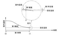
- the "first deviation”, “first predetermined value”, and “first time” will be explained with reference to FIG. 3.
- a solid line shows an example of a change in indoor temperature over time when the air conditioner 100 is operated in a cooling operation.
- the "first deviation” is the deviation of the indoor temperature from the set temperature (the temperature difference between the set temperature and the indoor temperature) as described above.
- the “first deviation” is calculated, for example, using the formula “(indoor temperature) ⁇ (set temperature)”.
- the "first predetermined value” is a determination value corresponding to the first deviation when it can be determined that the indoor temperature has almost reached the set temperature.
- the first predetermined value may be positive, negative or zero.
- the first deviation is equal to or less than the first predetermined value at time t1.
- the "first time” is the time from when the air conditioner 100 starts room temperature control (or changes the control content) until the indoor temperature reaches (or almost reaches) the set temperature, In the example shown in , it is the time from time t0 to time t1.
- the time t0 is, for example, the start time of operation of the air conditioner 100, the change time of the set temperature, the change time of the operation mode, etc.
- the "first time” is influenced by the installation environment of the air conditioner 100, and changes depending on, for example, differences in the insulation and airtightness of the room. If the "first time” is relatively small, it can be said that the heat insulation properties are good, and if the "first time” is relatively large, it can be said that the heat insulation properties are poor, for example.
- the setting unit 23 sets a “setting value” (compressor maximum rotation speed setting value) based on the “first time” calculated by the calculation unit 22.
- FIG. 4 shows a table T1 that defines setting examples of setting values in this embodiment. According to the table T1 shown in FIG. 4, for example, when the first time is within the first threshold, the setting unit 23 decreases the setting value from the current setting value. If the first time is greater than the first threshold and less than the second threshold, the setting unit 23 does not change the setting value from the current setting value. However, the second threshold is a larger value than the first threshold. If the first time is equal to or greater than the second threshold, the setting unit 23 increases the setting value from the current setting value.
- the first threshold value is, for example, a determination value by which it can be determined that the heat insulation properties are good.
- the second threshold value is, for example, a determination value at which it can be determined that the insulation property is poor.
- the setting of the "setting value" by the setting unit 23 includes cases where the "setting value” is changed and cases where the "setting value” is not changed. Note that the setting unit 23 increases or decreases the set value within the limits of the upper limit value of the rotation speed, such as the maximum rated rotation speed, and the limit of the lower limit value of the predetermined rotation speed.
- the setting unit 23 determines that the heat insulation is high and lowers the set value (eg, from 100 rps to 95 rps). Further, during the next operation, when the set temperature is reached within A minutes from the start of the cooling operation, the setting unit 23 lowers the set value again (eg, from 95 rps to 90 rps). Further, if the set temperature is not reached for more than B minutes (eg, 20 minutes) from the start of operation, the setting unit 23 increases the set value (eg, from 90 to 95 rps). Further, the setting unit 23 does not change the set value if the time required to reach the set temperature is A to B.
- a minutes eg, 10 minutes
- the setting unit 23 determines that the heat insulation is high and lowers the set value (eg, from 100 rps to 95 rps). Further, during the next operation, when the set temperature is reached within A minutes from the start of the cooling operation, the setting unit 23 lowers the set value again (eg, from 95 rps to
- the setting unit 23 automatically adjusts the set value (maximum rotation speed) of the compressor 2 to suit the room in which the air conditioner 100 is used.
- the first threshold value shown in FIG. 4 corresponds to the A minute
- the second threshold value corresponds to the B minute.
- the rotational speed is changed by a predetermined amount (for example, 5 rps).
- the increase/decrease is not limited to a constant value, and may be changed at a predetermined rate with respect to a variable or a current set value, for example.
- FIG. 5 shows an example of a setting value setting operation by the control device 20.
- the process shown in FIG. 5 is executed, for example, when the air conditioner 100 starts operating.
- the calculation unit 22 calculates a first time during which a first deviation, which is a deviation of the indoor temperature from the set temperature, is equal to or less than a first predetermined value (step S11).
- the setting unit 23 sets a set value for the maximum rotation speed of the compressor 2 based on the first time (step S12).
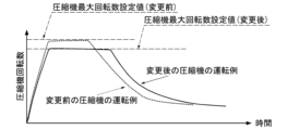
- FIG. 6 shows an example of changes over time in the rotation speed of the compressor 2 and the indoor temperature during cooling operation of the air conditioner 100.
- operation is started at time t0, and the rotation speed of the compressor 2 increases at a predetermined rate of change. Then, the rotation speed is controlled near the set value from time t02 to time t03 within a range that does not exceed the "set value" (compressor maximum rotation speed set value (before change)) at the start of operation. After time t03, the rotation speed gradually decreases, and at time t1, the first deviation becomes equal to or less than the first predetermined value, and the set value changes from the compressor maximum rotation speed setting value (before change) to the maximum compressor rotation speed.
- set value compressor maximum rotation speed set value (before change)
- FIG. 6 shows an example of how the rotation speed of the compressor 2 changes over time before and after the change. In the operation example after the change, compared to before the change, the operation time near the set value is extended, but the maximum rotation speed is suppressed.
- FIG. 8 is a schematic diagram for explaining a control device according to a second embodiment of the present disclosure.
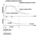
- FIG. 8 shows an example of changes over time in the rotation speed of the compressor 2 and the indoor temperature during cooling operation of the air conditioner 100 in the second embodiment.
- the configurations and operations of the air conditioner 100 and the control device 20 described with reference to FIGS. 1 to 5 are the same in the first embodiment and the second embodiment except for the following points. That is, in the first embodiment, as shown in FIG. 6, the set value is changed when the first time period during which the first deviation becomes equal to or less than the first predetermined value has elapsed.
- the second embodiment as shown in FIG. 8, the first time is predicted and the set value is changed before the first time elapses.
- the calculation unit 22 of the second embodiment calculates the first time by prediction before the first time elapses.
- the calculation unit 22 of the second embodiment creates a regression model based on each actual value of the set temperature, indoor temperature, outdoor temperature, rotation speed of the compressor 2, first time, etc., and uses the created regression model to calculate the regression model. Predict the first hour.
- the calculation unit 22 of the second embodiment creates a learned machine learning model that is machine learned based on at least the set temperature, the indoor temperature, the rotation speed of the compressor 2, and each actual value for the first time.
- the first time is predicted using the learned machine learning model.
- the indoor temperature may be only the value at the start of operation, or may include a plurality of time-series values before reaching the set temperature.
- the rotation speed may be only the maximum rotation speed (set value), or may include a plurality of time-series values before reaching the set temperature.
- the calculation unit 22 of the second embodiment calculates the lapse of the first time until a regression model can be created by acquiring a plurality of actual values. It is possible to change the setting value when the
- the first time can be predicted before the rotation speed approaches the maximum rotation speed (set value) (before time t02) (time t02) (time t02
- the set value can be changed (time t01) at a previous time t01), and the change in the set value can be reflected (made effective) in the current operation.
- FIG. 9 is a flowchart illustrating an example of the operation of the control device according to the third embodiment of the present disclosure.
- FIG. 10 is a schematic diagram for explaining a control device according to a third embodiment of the present disclosure. Note that the configuration and operation of the air conditioner 100 and the control device 20 described with reference to FIGS. 1 to 3 are the same in the first embodiment and the third embodiment except for the following points. That is, the calculation unit 22 of the first embodiment calculates the first time until the first deviation becomes equal to or less than the first predetermined value. Further, the setting unit 23 of the first embodiment sets the setting value based on the first time.
- the calculation unit 22 of the third embodiment further calculates the second deviation until the second deviation, which is the deviation of the radiant temperature measured indoors by the radiant temperature sensor 13 from the set temperature, becomes equal to or less than the second predetermined value. Calculate the time. Further, the setting unit 23 of the third embodiment sets the setting value based on the first time and the second time. Note that the second deviation, the second predetermined value, and the second time correspond to the case where the first deviation, the first predetermined value, and the indoor temperature at the first time are read as the radiant temperature.
- the calculation unit 22 of the third embodiment calculates the temperature at which the first deviation, which is the deviation of the indoor temperature from the set temperature, is equal to or less than the first predetermined value.
- One hour is calculated (step S31)
- a second time during which the second deviation, which is the deviation of the radiant temperature from the set temperature, is equal to or less than the second predetermined value is calculated (step S32).
- the setting unit 23 of the third embodiment sets a set value of the maximum rotation speed of the compressor 2 based on the first time and the second time (step S33).
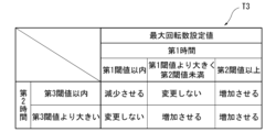
- FIG. 10 shows a table T3 that defines setting examples of setting values in this embodiment.
- the setting unit 23 decreases the set value from the current set value when the second time is within the third threshold. , the set value is not changed from the current set value when the second time is greater than the third threshold.
- the third threshold is a determination value for determining, for example, whether the insulation of the room is good or bad based on the temperature change of the wall or floor detected by the radiation temperature sensor.
- the setting unit 23 does not change the setting value from the current setting value when the second time is within the third threshold, and When the time is greater than the third threshold, the set value is increased from the current set value. Further, when the first time is equal to or greater than the second threshold, the setting unit 23 increases the set value from the current set value.
- the maximum rotation speed in addition to the indoor temperature, the maximum rotation speed can be adjusted to suit the room, taking into account changes in the temperature of the floor and walls.
- FIG. 11 is a flowchart illustrating an example of the operation of the control device according to the fourth embodiment of the present disclosure.
- FIG. 12 is a schematic diagram for explaining a control device according to a fourth embodiment of the present disclosure. Note that the configurations and operations of the air conditioner 100 and the control device 20 described with reference to FIGS. 1 to 3 are the same in the first embodiment and the fourth embodiment except for the following points. That is, the calculation unit 22 of the first embodiment calculates the first time until the first deviation becomes equal to or less than the first predetermined value. Further, the setting unit 23 of the first embodiment sets the setting value based on the first time.
- the calculation unit 22 of the fourth embodiment further calculates the temperature difference between the set temperature at the start of operation and the indoor temperature (however, the calculation of the temperature difference may be performed by the setting unit 23, for example).
- the setting unit 23 of the third embodiment sets the set value based on the temperature difference between the set temperature at the start of operation and the indoor temperature, and the first time.
- the calculation unit 22 of the fourth embodiment calculates the temperature difference between the set temperature at the start of operation and the indoor temperature (step S41), and A first time during which a first deviation, which is a deviation of the indoor temperature from the temperature, is equal to or less than a first predetermined value is calculated (step S42).
- the setting unit 23 of the fourth embodiment sets a set value for the maximum rotation speed of the compressor 2 based on the first time and the calculated temperature difference (step S43).
- FIG. 12 shows a table T4 that defines setting examples of setting values in this embodiment.
- the setting unit 23 when the first time is within the first threshold, the setting unit 23 does not change the set value when the temperature difference is within the fourth threshold, and when the temperature difference is within the fourth threshold.
- the set value is decreased by a change ⁇ 1
- the set value is decreased by a change ⁇ 2.
- the amount of change ⁇ 1 is smaller than the amount of change ⁇ 2.
- the fourth threshold is smaller than the fifth threshold.
- the setting unit 23 does not change the setting value.
- the setting unit 23 does not change the set value when the temperature difference is within the fourth threshold, and sets the set value when the temperature difference is greater than the fourth threshold and less than the fifth threshold.
- the value is increased by a change amount ⁇ 2
- the set value is increased by a change amount ⁇ 1.
- the set value is not changed without determining the insulation properties of the room, etc. You can do it like this.
- the amount of reduction when reducing the maximum rotation speed is increased compared to when the temperature difference is not large (less than the fifth threshold). At the same time, it is possible to reduce the amount of increase when increasing the maximum rotation speed.
- the maximum rotation speed can be adjusted to suit the room, taking into consideration the temperature difference at the start of operation.
- the first deviation is based on the first time until the first deviation becomes equal to or less than the first predetermined value.
- the maximum rotation speed of the compressor is controlled based on the set value set by The first time is a factor that is influenced by the insulation properties of the room, etc., and the maximum rotation speed of the compressor is a factor that affects power consumption. Therefore, adjusting the maximum rotation speed according to the first time means adjusting the degree of reduction in power consumption according to the insulation properties of the room, etc. Therefore, according to the control device, control method, and air conditioner of the embodiment, by adjusting the maximum rotation speed according to the first time, it is possible to maintain both comfort and reduce power consumption.
- the maximum rotation speed is increased or decreased depending on the comparison result between the first time and the predetermined thresholds (the first threshold and the second threshold).
- the amount of increase or decrease may be changed depending on the magnitude of the difference from a predetermined threshold value, that is, depending on the length of time until the set temperature is reached.
- actual values of outdoor temperature, humidity, etc. can be further used.
- temperature changes in both may be considered, or one of them (for example, the one that changes slowly) may be selectively considered.
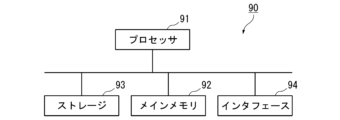
- FIG. 13 is a schematic block diagram showing the configuration of a computer according to at least one embodiment.
- Computer 90 includes a processor 91, main memory 92, storage 93, and interface 94.
- the control device 20 described above is implemented in the computer 90.
- the operations of each processing section described above are stored in the storage 93 in the form of a program.
- the processor 91 reads the program from the storage 93, expands it into the main memory 92, and executes the above processing according to the program. Further, the processor 91 reserves storage areas corresponding to each of the above-mentioned storage units in the main memory 92 according to the program.
- the program may be one for realizing a part of the functions to be performed by the computer 90.
- the program may function in combination with other programs already stored in storage or in combination with other programs installed in other devices.
- the computer may include a custom LSI (Large Scale Integrated Circuit) such as a PLD (Programmable Logic Device) in addition to or in place of the above configuration.
- PLDs include PAL (Programmable Array Logic), GAL (Generic Array Logic), CPLD (Complex Programmable Logic Device), FPGA (Field Programmable Gate Array), and the like.
- PLDs Programmable Logic Device
- PAL Programmable Array Logic
- GAL Generic Array Logic
- CPLD Complex Programmable Logic Device
- FPGA Field Programmable Gate Array
- Storage 93 examples include HDD (Hard Disk Drive), SSD (Solid State Drive), magnetic disk, magneto-optical disk, CD-ROM (Compact Disc Read Only Memory), and DVD-ROM (Digital Versatile Disc Read Only Memory). , semiconductor memory, etc.
- Storage 93 may be an internal medium connected directly to the bus of computer 90, or may be an external medium connected to computer 90 via an interface 94 or a communication line. Furthermore, when this program is distributed to the computer 90 via a communication line, the computer 90 that received the distribution may develop the program in the main memory 92 and execute the above processing.
- storage 93 is a non-transitory, tangible storage medium.
- control device 20 described in each embodiment is understood as follows, for example.
- the control device 20 includes an air conditioner 100 having a refrigerant circuit 1 that circulates refrigerant compressed by a compressor 2 between an indoor heat exchanger 3 and an outdoor heat exchanger 4. , a control device 20 that controls the first deviation, which is the deviation of the indoor temperature from the set temperature, to be small, and controls the maximum rotation speed of the compressor 2 based on a predetermined set value, and
- the calculation unit 22 includes a calculation unit 22 that calculates a first time until one deviation becomes equal to or less than a first predetermined value, and a setting unit 23 that sets the set value based on the first time. According to this aspect and the following aspects, it is possible to maintain both comfort and reduce power consumption.
- a control device 20 is the control device 20 of (1), in which the setting unit 23 decreases the set value when the first time is equal to or less than a first threshold. , the set value is not changed when it is less than a second threshold that is larger than the first threshold and larger than the first threshold, and the set value is increased when it is greater than or equal to the second threshold.
- the control device 20 is the control device 20 of (1) or (2), in which the calculation unit 22 calculates the first time by prediction before the first time elapses. Calculate the time.
- the control device 20 according to the fourth aspect is the control device 20 of (1) to (3), in which the calculation unit 22 includes at least the set temperature, the indoor temperature, the rotation speed, and the The first time is predicted using a learned machine learning model that is machine learned based on each actual value of the first time.
- the control device 20 is the control device 20 of (1) to (4), in which the calculation unit 22 further calculates the radiation temperature measured by the radiation temperature sensor in the room.
- the setting unit 23 calculates a second time until a second deviation, which is a deviation from the set temperature, becomes equal to or less than a second predetermined value, and the setting unit 23 sets the set value based on the first time and the second time. Set.
- the maximum rotation speed can be set in consideration of temperature changes on the walls and floor of the room.
- the control device 20 according to the sixth aspect is the control device 20 according to (1) to (5), in which the setting section is configured to adjust the temperature difference between the set temperature at the start of operation and the indoor temperature. , the set value is set based on the first time.
Landscapes
- Engineering & Computer Science (AREA)
- Mechanical Engineering (AREA)
- General Engineering & Computer Science (AREA)
- Physics & Mathematics (AREA)
- Thermal Sciences (AREA)
- Chemical & Material Sciences (AREA)
- Combustion & Propulsion (AREA)
- Signal Processing (AREA)
- Fuzzy Systems (AREA)
- Mathematical Physics (AREA)
- Human Computer Interaction (AREA)
- Air Conditioning Control Device (AREA)
Abstract
Description
本願は、2022年8月26日に、日本に出願された特願2022-134898号に基づき優先権を主張し、その内容をここに援用する。
(空気調和機の構成)
図1は、本開示の第1実施形態に係る空気調和機の概要を示す図である。図1に示すように、本実施形態に係る空気調和機100は、圧縮機2、室内熱交換器3、室外熱交換器4、膨張弁5、四方弁6、および、これらを接続する冷媒配管7を含む冷媒回路1と、この冷媒回路1を制御する制御装置20とを備える。例えば、室内機8には室内熱交換器3が設けられ、室外機9には圧縮機2、室外熱交換器4、膨張弁5、および四方弁6が設けられる。また、室内機8には、室内機8が設置されている部屋の室内温度を検知する室内温度センサ11と、その部屋の壁や床からの放射温度を検知する放射温度センサ13が設けられている。また、室外機9には、室外温度を検知する室外温度センサ12が設けられている。また、制御装置20では、例えばユーザが操作するリモコン、スマートフォン等の送受信部30によって空気調和機100の設定温度や運転モードが設定される。なお、室内温度センサ11は、例えば室内熱交換器3へ吸い込まれる空気の温度を検知する。また、放射温度センサ13は、例えば、サーモパイルセンサであり、サーモパイル(赤外線センサ)と、物体から放射された赤外線をサーモパイルに集光する光学系と、サーモパイルの出力信号を処理する信号処理回路等を備える。なお、設定温度は、室温制御の目標温度である。運転モードは、暖房運転、冷房運転等の運転方式である。
図2は、本開示の第1実施形態に係る制御装置20の構成例を示す図である。図3、図4、図6および図7は、本開示の第1実施形態に係る制御装置20を説明するための模式図である。図5は、本開示の第1実施形態に係る制御装置20の動作例を示すフローチャートである。
図5は、制御装置20による設定値の設定動作の例を示す。図5に示す処理は、例えば空気調和機100の運転開始時に実行される。図5に示す処理では、まず、算出部22が、設定温度に対する室内温度の偏差である第1偏差が第1所定値以下となる第1時間を算出する(ステップS11)。次に、設定部23が、第1時間に基づき圧縮機2の最大回転数の設定値を設定する(ステップS12)。
圧縮機は基本的に回転数が高いと消費電力が大きくなる。本実施形態によれば、最大回転数を部屋に合わせて調整することで快適性を損なわず、消費電力を抑えることが可能となる。すなわち、本実施形態によれば、快適性の維持と消費電力の低減を両立させることができる。
図8は、本開示の第2実施形態に係る制御装置を説明するための模式図である。図8は、第2実施形態おける空気調和機100の冷房運転における圧縮機2の回転数と室内温度の時間変化の例を示す。なお、図1~図5を参照して説明した空気調和機100および制御装置20の構成および動作については、第1実施形態と第2実施形態で次の点を除き同一である。すなわち、第1実施形態では、図6に示すように、第1偏差が第1所定値以下となる第1時間が経過した場合に設定値が変更された。一方、第2実施形態では、図8に示すように、第1時間が経過する前に、第1時間を予測し、設定値を変更する。この場合、第2実施形態の算出部22は、第1時間が経過する前に、予測によって第1時間を算出することになる。
図9は、本開示の第3実施形態に係る制御装置の動作例を示すフローチャートである。図10は、本開示の第3実施形態に係る制御装置を説明するための模式図である。なお、図1~図3を参照して説明した空気調和機100および制御装置20の構成および動作については、第1実施形態と第3実施形態で次の点を除き同一である。すなわち、第1実施形態の算出部22は、第1偏差が第1所定値以下となるまでの第1時間を算出する。また、第1実施形態の設定部23は、第1時間に基づき設定値を設定する。これに対し、第3実施形態の算出部22は、さらに、室内において放射温度センサ13で計測された放射温度の設定温度に対する偏差である第2偏差が第2所定値以下となるまでの第2時間を算出する。また、第3実施形態の設定部23は、第1時間と第2時間とに基づいて設定値を設定する。なお、第2偏差、第2所定値および第2時間は、第1偏差、第1所定値および第1時間における室内温度を放射温度に読み替えた場合に対応する。
図11は、本開示の第4実施形態に係る制御装置の動作例を示すフローチャートである。図12は、本開示の第4実施形態に係る制御装置を説明するための模式図である。なお、図1~図3を参照して説明した空気調和機100および制御装置20の構成および動作については、第1実施形態と第4実施形態で次の点を除き同一である。すなわち、第1実施形態の算出部22は、第1偏差が第1所定値以下となるまでの第1時間を算出する。また、第1実施形態の設定部23は、第1時間に基づき設定値を設定する。これに対し、第4実施形態の算出部22は、さらに、運転開始時の設定温度と室内温度との温度差を算出する(ただし、温度差の算出は例えば設定部23が行ってもよい)。また、第3実施形態の設定部23は、運転開始時の設定温度と室内温度との温度差と、第1時間とに基づき設定値を設定する。
上記構成の制御装置、制御方法および空気調和機では、設定温度に対する室内温度の偏差である第1偏差を小さくする制御において、第1偏差が第1所定値以下となるまでの第1時間に基づいて設定した設定値に基づき圧縮機の最大回転数が制御される。第1時間は部屋の断熱性等に影響される要素であり、圧縮機の最大回転数は消費電力に影響を与える要素である。このため、第1時間に応じて最大回転数を調整することは、部屋の断熱性等に応じて消費電力の低減の度合いを調整することになる。したがって、実施形態の制御装置、制御方法および空気調和機によれば、最大回転数を第1時間に応じて調整することで、快適性の維持と消費電力の低減を両立させることができる。
以上、本開示の実施の形態について図面を参照して詳述したが、具体的な構成はこの実施の形態に限られるものではなく、本開示の要旨を逸脱しない範囲の設計変更等も含まれる。例えば、各実施形態の構成および動作は、適宜組み合わせることができる。なお、上記実施形態では、第1時間と所定の閾値(第1閾値および第2閾値)との比較結果に応じて最大回転数を例えば増加または減少させることとしているが、例えば、第1時間と所定の閾値との差の大きさに応じて、すなわち、設定温度に到達するまでの時間の長さによって、上げ幅や下げ幅を変化させてもよい。また、回帰モデルを作成する際には、さらに、室外温度、湿度等の実績値を用いることができる。また、室内温度と放射温度を考慮する場合、両者の温度変化を考慮してもよいし、どちらか一方(例えば変化が遅い方)を選択的に考慮するようにしてもよい。
図13は、少なくとも1つの実施形態に係るコンピュータの構成を示す概略ブロック図である。
コンピュータ90は、プロセッサ91、メインメモリ92、ストレージ93、および、インタフェース94を備える。
上述の制御装置20は、コンピュータ90に実装される。そして、上述した各処理部の動作は、プログラムの形式でストレージ93に記憶されている。プロセッサ91は、プログラムをストレージ93から読み出してメインメモリ92に展開し、当該プログラムに従って上記処理を実行する。また、プロセッサ91は、プログラムに従って、上述した各記憶部に対応する記憶領域をメインメモリ92に確保する。
各実施形態に記載の制御装置20は、例えば以下のように把握される。
1…冷媒回路
2…圧縮機
3…室内熱交換器
4…室外熱交換器
5…膨張弁
6…四方弁
7…冷媒配管
8…室内機
9…室外機
11…室内温度センサ
12…室外温度センサ
13…放射温度センサ
20…制御装置
21…空調制御部
22…算出部
23…設定部
Claims (8)
- 圧縮機によって圧縮された冷媒を室内熱交換器と室外熱交換器との間で循環させる冷媒回路を有する空気調和機を、設定温度に対する室内温度の偏差である第1偏差が小さくなるように制御する制御装置であって、
所定の設定値に基づき前記圧縮機の最大回転数を制御するものであり、
前記第1偏差が第1所定値以下となるまでの第1時間を算出する算出部と、
前記第1時間に基づき前記設定値を設定する設定部と
を備える制御装置。 - 前記設定部は、前記第1時間が、第1閾値以下の場合に前記設定値を減少させ、前記第1閾値より大きい第2閾値未満で前記第1閾値より大きい場合に前記設定値を変更せず、前記第2閾値以上の場合に前記設定値を増加させる
請求項1に記載の制御装置。 - 前記算出部は、前記第1時間が経過する前に、予測によって前記第1時間を算出する 請求項2に記載の制御装置。
- 前記算出部は、少なくとも、前記設定温度、前記室内温度、前記最大回転数および前記第1時間の各実績値に基づき機械学習された学習済み機械学習モデルを用いて、前記第1時間を予測する
請求項3に記載の制御装置。 - 前記算出部は、さらに、室内において放射温度センサで計測された放射温度の前記設定温度に対する偏差である第2偏差が第2所定値以下となるまでの第2時間を算出し、
前記設定部は、前記第1時間と前記第2時間とに基づいて前記設定値を設定する
請求項4に記載の制御装置。 - 前記設定部は、運転開始時の前記設定温度と前記室内温度との温度差と、前記第1時間とに基づき前記設定値を設定する
請求項5に記載の制御装置。 - 圧縮機によって圧縮された冷媒を室内熱交換器と室外熱交換器との間で循環させる冷媒回路を有する空気調和機を、設定温度に対する室内温度の偏差である第1偏差が小さくなるように制御する制御方法であって、
所定の設定値に基づき前記圧縮機の最大回転数を制御するものであり、
前記第1偏差が第1所定値以下となるまでの第1時間を算出するステップと、
前記第1時間に基づき前記設定値を設定するステップと
を含む制御方法。 - 圧縮機によって圧縮された冷媒を室内熱交換器と室外熱交換器との間で循環させる冷媒回路と、
設定温度に対する室内温度の偏差である第1偏差が小さくなるように前記圧縮機の回転数を制御するものであって、所定の設定値に基づき前記圧縮機の最大回転数を制御するものであり、前記第1偏差が第1所定値以下となるまでの第1時間を算出する算出部と、前記第1時間に基づき前記設定値を設定する設定部とを有する制御装置と、
を備える空気調和機。
Priority Applications (2)
| Application Number | Priority Date | Filing Date | Title |
|---|---|---|---|
| EP23857317.4A EP4560215A4 (en) | 2022-08-26 | 2023-08-21 | CONTROL DEVICE, CONTROL METHOD AND AIR CONDITIONER |
| AU2023331083A AU2023331083A1 (en) | 2022-08-26 | 2023-08-21 | Control device, control method, and air conditioner |
Applications Claiming Priority (2)
| Application Number | Priority Date | Filing Date | Title |
|---|---|---|---|
| JP2022134898A JP2024031381A (ja) | 2022-08-26 | 2022-08-26 | 制御装置、制御方法および空気調和機 |
| JP2022-134898 | 2022-08-26 |
Publications (1)
| Publication Number | Publication Date |
|---|---|
| WO2024043206A1 true WO2024043206A1 (ja) | 2024-02-29 |
Family
ID=90013289
Family Applications (1)
| Application Number | Title | Priority Date | Filing Date |
|---|---|---|---|
| PCT/JP2023/029993 Ceased WO2024043206A1 (ja) | 2022-08-26 | 2023-08-21 | 制御装置、制御方法および空気調和機 |
Country Status (4)
| Country | Link |
|---|---|
| EP (1) | EP4560215A4 (ja) |
| JP (1) | JP2024031381A (ja) |
| AU (1) | AU2023331083A1 (ja) |
| WO (1) | WO2024043206A1 (ja) |
Families Citing this family (1)
| Publication number | Priority date | Publication date | Assignee | Title |
|---|---|---|---|---|
| WO2025220665A1 (ja) * | 2024-04-15 | 2025-10-23 | 三菱重工サーマルシステムズ株式会社 | 制御システム、空調システム、制御方法及びプログラム |
Citations (5)
| Publication number | Priority date | Publication date | Assignee | Title |
|---|---|---|---|---|
| JPH11173633A (ja) * | 1997-12-09 | 1999-07-02 | Sanyo Electric Co Ltd | 暖房システム |
| JP2017203581A (ja) | 2016-05-11 | 2017-11-16 | 日立ジョンソンコントロールズ空調株式会社 | 空気調和機 |
| JP2021050853A (ja) * | 2019-09-24 | 2021-04-01 | パナソニックIpマネジメント株式会社 | 空気調和機の運転を開始させる方法および制御装置 |
| WO2021117234A1 (ja) * | 2019-12-13 | 2021-06-17 | 三菱電機株式会社 | モデル共有システム、モデル管理装置、および空気調和装置の制御装置 |
| JP2022134898A (ja) | 2021-03-04 | 2022-09-15 | 住友重機械イオンテクノロジー株式会社 | イオン注入装置およびイオン注入方法 |
Family Cites Families (2)
| Publication number | Priority date | Publication date | Assignee | Title |
|---|---|---|---|---|
| EP1834138B1 (en) * | 2005-01-03 | 2017-08-02 | Arçelik Anonim Sirketi | A cooling device and a control method |
| DE102006044999B4 (de) * | 2005-09-29 | 2010-04-01 | Danfoss Compressors Gmbh | Verfahren und Regeleinheit zur Regelung einer Drehgeschwindigkeit eines Verdichters |
-
2022
- 2022-08-26 JP JP2022134898A patent/JP2024031381A/ja active Pending
-
2023
- 2023-08-21 WO PCT/JP2023/029993 patent/WO2024043206A1/ja not_active Ceased
- 2023-08-21 AU AU2023331083A patent/AU2023331083A1/en active Pending
- 2023-08-21 EP EP23857317.4A patent/EP4560215A4/en active Pending
Patent Citations (5)
| Publication number | Priority date | Publication date | Assignee | Title |
|---|---|---|---|---|
| JPH11173633A (ja) * | 1997-12-09 | 1999-07-02 | Sanyo Electric Co Ltd | 暖房システム |
| JP2017203581A (ja) | 2016-05-11 | 2017-11-16 | 日立ジョンソンコントロールズ空調株式会社 | 空気調和機 |
| JP2021050853A (ja) * | 2019-09-24 | 2021-04-01 | パナソニックIpマネジメント株式会社 | 空気調和機の運転を開始させる方法および制御装置 |
| WO2021117234A1 (ja) * | 2019-12-13 | 2021-06-17 | 三菱電機株式会社 | モデル共有システム、モデル管理装置、および空気調和装置の制御装置 |
| JP2022134898A (ja) | 2021-03-04 | 2022-09-15 | 住友重機械イオンテクノロジー株式会社 | イオン注入装置およびイオン注入方法 |
Non-Patent Citations (1)
| Title |
|---|
| See also references of EP4560215A4 |
Also Published As
| Publication number | Publication date |
|---|---|
| EP4560215A1 (en) | 2025-05-28 |
| AU2023331083A1 (en) | 2025-03-13 |
| EP4560215A4 (en) | 2025-11-26 |
| JP2024031381A (ja) | 2024-03-07 |
Similar Documents
| Publication | Publication Date | Title |
|---|---|---|
| JP3137114B1 (ja) | 多室形空気調和装置 | |
| CN111174372B (zh) | 一种空调控制方法、装置、存储介质及空调 | |
| US9074787B2 (en) | Operation controller for compressor and air conditioner having the same | |
| US11262092B2 (en) | Air conditioning system including a ventilator that supplies humidified outdoor air | |
| CN107940827A (zh) | 多联机系统及其冷媒分配控制方法和装置 | |
| JP5695861B2 (ja) | 外気処理空調機およびそれを用いたマルチ空調システム | |
| CN104406251A (zh) | 空调器除湿方法及空调器 | |
| JP6890706B1 (ja) | 空気調和システムおよび制御方法 | |
| WO2021175013A1 (zh) | 空调器及其控制方法 | |
| CN107525217B (zh) | 一种空调器控制方法、控制装置及空调器 | |
| CN104990232A (zh) | 空调器的控制方法、控制装置和控制系统 | |
| CN106839267A (zh) | 空调系统的除湿方法、除湿装置及空调器 | |
| JP6109307B2 (ja) | 空気調和装置 | |
| CN113865057B (zh) | 湿度控制方法、装置及空调器 | |
| CN108019892A (zh) | 多联式空调系统的控制方法 | |
| CN108151249A (zh) | 运行控制方法、装置、空调器和计算机可读存储介质 | |
| KR101948100B1 (ko) | 공기조화기 및 그 제어방법 | |
| CN101818975A (zh) | 机房空调 | |
| CN111336645A (zh) | 一种空调控制方法、装置及空调器 | |
| JP2021105485A (ja) | 空気調和機、および空気調和システム | |
| JP3816782B2 (ja) | 空気調和機 | |
| JP2018124033A (ja) | 空調制御システムおよび空調制御方法 | |
| JP2024031381A (ja) | 制御装置、制御方法および空気調和機 | |
| JP2009014321A (ja) | 空気調和機 | |
| CN114738924B (zh) | 多联机空调器及其控制方法和控制装置 |
Legal Events
| Date | Code | Title | Description |
|---|---|---|---|
| 121 | Ep: the epo has been informed by wipo that ep was designated in this application |
Ref document number: 23857317 Country of ref document: EP Kind code of ref document: A1 |
|
| WWE | Wipo information: entry into national phase |
Ref document number: 2023857317 Country of ref document: EP Ref document number: AU2023331083 Country of ref document: AU |
|
| ENP | Entry into the national phase |
Ref document number: 2023857317 Country of ref document: EP Effective date: 20250221 |
|
| ENP | Entry into the national phase |
Ref document number: 2023331083 Country of ref document: AU Date of ref document: 20230821 Kind code of ref document: A |
|
| NENP | Non-entry into the national phase |
Ref country code: DE |
|
| WWP | Wipo information: published in national office |
Ref document number: 2023857317 Country of ref document: EP |