WO2024043263A1 - 情報処理装置、情報処理システム、情報処理方法及びコンピュータプログラム - Google Patents
情報処理装置、情報処理システム、情報処理方法及びコンピュータプログラム Download PDFInfo
- Publication number
- WO2024043263A1 WO2024043263A1 PCT/JP2023/030258 JP2023030258W WO2024043263A1 WO 2024043263 A1 WO2024043263 A1 WO 2024043263A1 JP 2023030258 W JP2023030258 W JP 2023030258W WO 2024043263 A1 WO2024043263 A1 WO 2024043263A1
- Authority
- WO
- WIPO (PCT)
- Prior art keywords
- target space
- data
- information processing
- processing device
- information
- Prior art date
- Legal status (The legal status is an assumption and is not a legal conclusion. Google has not performed a legal analysis and makes no representation as to the accuracy of the status listed.)
- Ceased
Links
Images




Classifications
-
- G—PHYSICS
- G06—COMPUTING OR CALCULATING; COUNTING
- G06T—IMAGE DATA PROCESSING OR GENERATION, IN GENERAL
- G06T19/00—Manipulating three-dimensional [3D] models or images for computer graphics
- G06T19/006—Mixed reality
-
- G—PHYSICS
- G06—COMPUTING OR CALCULATING; COUNTING
- G06F—ELECTRIC DIGITAL DATA PROCESSING
- G06F30/00—Computer-aided design [CAD]
- G06F30/10—Geometric CAD
- G06F30/12—Geometric CAD characterised by design entry means specially adapted for CAD, e.g. graphical user interfaces [GUI] specially adapted for CAD
-
- G—PHYSICS
- G06—COMPUTING OR CALCULATING; COUNTING
- G06F—ELECTRIC DIGITAL DATA PROCESSING
- G06F30/00—Computer-aided design [CAD]
- G06F30/20—Design optimisation, verification or simulation
- G06F30/27—Design optimisation, verification or simulation using machine learning, e.g. artificial intelligence, neural networks, support vector machines [SVM] or training a model
-
- G—PHYSICS
- G06—COMPUTING OR CALCULATING; COUNTING
- G06F—ELECTRIC DIGITAL DATA PROCESSING
- G06F30/00—Computer-aided design [CAD]
- G06F30/20—Design optimisation, verification or simulation
- G06F30/28—Design optimisation, verification or simulation using fluid dynamics, e.g. using Navier-Stokes equations or computational fluid dynamics [CFD]
-
- G—PHYSICS
- G06—COMPUTING OR CALCULATING; COUNTING
- G06V—IMAGE OR VIDEO RECOGNITION OR UNDERSTANDING
- G06V10/00—Arrangements for image or video recognition or understanding
- G06V10/40—Extraction of image or video features
- G06V10/44—Local feature extraction by analysis of parts of the pattern, e.g. by detecting edges, contours, loops, corners, strokes or intersections; Connectivity analysis, e.g. of connected components
-
- G—PHYSICS
- G06—COMPUTING OR CALCULATING; COUNTING
- G06V—IMAGE OR VIDEO RECOGNITION OR UNDERSTANDING
- G06V20/00—Scenes; Scene-specific elements
- G06V20/20—Scenes; Scene-specific elements in augmented reality scenes
-
- G—PHYSICS
- G06—COMPUTING OR CALCULATING; COUNTING
- G06V—IMAGE OR VIDEO RECOGNITION OR UNDERSTANDING
- G06V20/00—Scenes; Scene-specific elements
- G06V20/50—Context or environment of the image
- G06V20/52—Surveillance or monitoring of activities, e.g. for recognising suspicious objects
-
- G—PHYSICS
- G06—COMPUTING OR CALCULATING; COUNTING
- G06V—IMAGE OR VIDEO RECOGNITION OR UNDERSTANDING
- G06V20/00—Scenes; Scene-specific elements
- G06V20/60—Type of objects
- G06V20/64—Three-dimensional [3D] objects
-
- G—PHYSICS
- G06—COMPUTING OR CALCULATING; COUNTING
- G06F—ELECTRIC DIGITAL DATA PROCESSING
- G06F2111/00—Details relating to CAD techniques
- G06F2111/10—Numerical modelling
-
- G—PHYSICS
- G06—COMPUTING OR CALCULATING; COUNTING
- G06F—ELECTRIC DIGITAL DATA PROCESSING
- G06F2119/00—Details relating to the type or aim of the analysis or the optimisation
- G06F2119/08—Thermal analysis or thermal optimisation
-
- G—PHYSICS
- G06—COMPUTING OR CALCULATING; COUNTING
- G06T—IMAGE DATA PROCESSING OR GENERATION, IN GENERAL
- G06T2210/00—Indexing scheme for image generation or computer graphics
- G06T2210/04—Architectural design, interior design
-
- G—PHYSICS
- G06—COMPUTING OR CALCULATING; COUNTING
- G06V—IMAGE OR VIDEO RECOGNITION OR UNDERSTANDING
- G06V2201/00—Indexing scheme relating to image or video recognition or understanding
- G06V2201/07—Target detection
Definitions
- the present disclosure relates to an information processing device, an information processing system, an information processing method, and a computer program.
- Patent Document 1 discloses a technique of creating model data indicating the shape of an object based on three-dimensional point group data and performing fluid calculation using the created model data.
- Patent Document 2 discloses a technique for creating a database that combines three-dimensional point cloud data and images, and identifying the position of an object by matching this database with an image of the object.
- An object of the present disclosure is to provide an information processing device, etc. that can associate and output attributes and positions of objects included in a target space based on target space data obtained by measuring the target space from multiple positions. It's about doing.
- An information processing device includes an acquisition unit that acquires target space data obtained by measuring the inside of the target space from a plurality of positions, and a processing unit that processes the acquired data.
- the processing unit recognizes the attributes and positions of objects in the target space that affect the environment of the target space from the acquired target space data, and adds the attributes and positions of the objects in the target space to the target space data. Output in association.
- An information processing device is an information processing device according to the first aspect, which uses the target space data acquired by the acquisition unit and the attributes and positions of objects in the target space. Based on the target space, an augmented reality image of the target space is created that reflects attributes and positions of objects in the target space that affect the environment of the target space.
- An information processing device is an information processing device according to the first aspect or the second aspect, and includes information about the target space data acquired by the acquisition unit and objects in the target space. Based on the attributes and positions, a three-dimensional spatial model of the target space is created that reflects the attributes and positions of objects in the target space that affect the environment of the target space.
- An information processing device includes an acquisition unit that acquires target space data obtained by measuring inside a target space from a plurality of positions, and a processing unit, and the processing unit includes: Based on the target space data acquired by the acquisition unit, the attributes and positions of objects that influence the environment of the target space are recognized, and the target space data acquired by the acquisition unit and the attributes and positions of the objects are recognized. Based on this, the attributes and positions of the object with respect to the environment of the target space are output in association with each other.
- An information processing apparatus is an information processing apparatus according to the 1-2 aspect, in which the target space data acquired by the acquisition unit and the attribute and position of the object are A three-dimensional spatial model of the target space is created based on the attributes and positions of the object with respect to the environment of the target space.
- An information processing apparatus is an information processing apparatus according to any one of the first to third aspects, and 1-2 and 2-2,
- the three-dimensional space model is a model for predicting the environment of the target space.
- An information processing apparatus is an information processing apparatus according to any one of the first to fourth aspects, and the 1-2 and 2-2 aspects,
- Objects in the target space include objects that affect the airflow in the target space, objects that affect the thermal environment of the target space, objects that affect the air quality of the target space, and objects that control the environment of the target space. Contains at least one of the following.
- An information processing device is an information processing device according to any one of the first to fifth aspects, 1-2, and 2-2, which By changing the model, capacity, location, and control, we will calculate the improvement effect in the target space.
- An information processing apparatus is an information processing apparatus according to any one of the first to fifth aspects, and the 1-2 and 2-2 aspects,
- the objects in the target space include at least one of fixtures, fittings, people, industrial machinery, plants, air conditioners, and ventilation devices.
- An information processing apparatus is an information processing apparatus according to any one of the first to sixth aspects, and the 1-2 and 2-2 aspects,
- the object in the target space includes an air conditioner or a ventilation device, and the processing unit recognizes an air terminal of the air conditioner or the ventilation device and determines whether the air terminal is an inlet or an outlet. do.
- An information processing apparatus is an information processing apparatus according to any one of the first to seventh aspects, and the 1-2 and 2-2 aspects,
- the processing unit acquires duct system data representing a duct system related to the suction port or the air outlet in the target space, and based on the acquired duct system data, Determine the exit.
- An information processing apparatus is an information processing apparatus according to any one of the first to eighth aspects, and the 1-2 and 2-2 aspects,
- the duct system data includes orientation information and outline information indicating the orientation and outline of the duct system, and the processing unit acquires orientation information related to the orientation of the target space, and uses the acquired orientation information and the target space.
- An information processing apparatus is an information processing apparatus according to any one of the first to ninth aspects, and the 1-2 and 2-2 aspects,
- the processing unit acquires thermography data of the target space, and determines the inlet or the outlet based on the acquired thermography data.
- An information processing apparatus is an information processing apparatus according to any one of the first to tenth aspects, and the 1-2 and 2-2 aspects,
- the target space data includes image data of the target space
- the processing unit calculates a feature amount related to the inlet or the outlet based on the acquired image data, and applies the feature amount to the calculated feature amount. Based on this, the inlet or the outlet is determined.
- An information processing apparatus is an information processing apparatus according to any one of the first to eleventh aspects, and the 1-2 and 2-2 aspects, and is
- the attributes of the object in the space include at least one of the dimensions, shape, sensible heat, latent heat, air volume, wind direction, and wind speed of the object in the target space.
- An information processing apparatus is an information processing apparatus according to any one of the first to twelfth aspects, and the 1-2 and 2-2 aspects,
- the processing unit creates the three-dimensional space model including thermal boundary conditions according to attributes of objects in the target space.
- An information processing apparatus is an information processing apparatus according to any one of the first to thirteenth aspects, and the 1-2 and 2-2 aspects,
- the processing unit acquires piping system data representing a piping system of an air conditioner in the target space, and creates the three-dimensional space model including thermal boundary conditions of the air conditioner based on the acquired piping system data. .
- An information processing apparatus is an information processing apparatus according to any one of the first to fourteenth aspects, and the 1-2 and 2-2 aspects
- the piping system data includes orientation information and outline information indicating the orientation and outline of the piping system
- the processing unit acquires orientation information related to the orientation of the target space, and uses the acquired orientation information and the target space.
- the position of the target space represented by the target space data and the piping system represented by the piping system data based on information representing the external shape of the target space based on spatial data and the piping system data. Make adjustments.
- An information processing apparatus is an information processing apparatus according to any one of the first to fifteenth aspects, and the 1-2 and 2-2 aspects,
- the processing unit acquires thermography data of the target space, and creates the three-dimensional space model including the temperature of the object as a thermal boundary condition based on the acquired thermography data.
- An information processing apparatus is an information processing apparatus according to any one of the first to sixteenth aspects, and the 1-2 and 2-2 aspects,
- the processing unit acquires thermography data of the target space, outside temperature data of the target space, sunlight amount data, and thickness data of the fittings, and based on each of the acquired data, sets the thermal conductivity of the fittings to thermal boundary conditions.
- the three-dimensional space model is created including:
- An information processing apparatus is an information processing apparatus according to any one of the first to seventeenth aspects, and the 1-2 and 2-2 aspects,
- the processing unit accepts editing of attributes and positions of objects in the target space, and changes the three-dimensional space model.
- An information processing apparatus is an information processing apparatus according to any one of the first to eighteenth aspects, and the 1-2 and 2-2 aspects,
- the processing unit receives addition of an object in the target space and changes the three-dimensional space model.
- An information processing apparatus is an information processing apparatus according to any one of the first to nineteenth aspects, and the 1-2 and 2-2 aspects,
- the acquisition unit acquires the target space data obtained by moving or rotating a measuring device that measures a physical quantity related to a shape in the target space.
- An information processing apparatus is an information processing apparatus according to any one of the first to twentieth aspects, and the 1-2 and 2-2 aspects,
- the processing unit specifies the target space and the position of the object in the target space by self-position estimation processing or line-of-sight direction estimation processing.
- An information processing apparatus is an information processing apparatus according to any one of the first to twenty-first aspects, and the 1-2 and 2-2 aspects,
- the acquisition unit acquires orientation information related to the orientation of the target space, and the processing unit creates the three-dimensional space model including the orientation information acquired by the acquisition unit or information based on the orientation information. .
- An information processing apparatus is an information processing apparatus according to any one of the first to twenty-second aspects, and the 1-2 and 2-2 aspects,
- the azimuth information is information based on the latitude, longitude, and time of the target space, and the position of a celestial body, or information based on the latitude, longitude, and time of the target space, and the direction and length of an indoor shadow.
- An information processing apparatus is an information processing apparatus according to any one of the first to twenty-third aspects, and the 1-2 and 2-2 aspects,
- the target space data includes RGB data and time data
- the processing unit specifies the orientation of the target space based on the RGB data and the time data, and generates orientation information indicating the identified orientation or the orientation.
- the three-dimensional spatial model including information based on the information is created.
- An information processing apparatus is an information processing apparatus according to any one of the first to twenty-fourth aspects, and the 1-2 and 2-2 aspects,
- the target space data includes RGB data and time data
- the processing unit identifies a usage scene of the target space based on the RGB data and the time data.
- An information processing apparatus is an information processing apparatus according to any one of the first to twenty-fifth aspects, and the 1-2 and 2-2 aspects, The processing unit determines whether the target space data includes duplicate objects in the target space.
- An information processing apparatus is an information processing apparatus according to any one of the first to twenty-sixth aspects, and the 1-2 and 2-2 aspects, When the processing unit recognizes the objects included in the target space in duplicate, the processing unit excludes the duplicate objects.
- An information processing apparatus is an information processing apparatus according to any one of the first to twenty-seventh aspects, and the 1-2 and 2-2 aspects, Based on the target space data acquired by the acquisition unit, the attribute and position of the concealed object in the target space are recognized, and the attribute and position of the object in the target space are recognized by the target space data acquired by the acquisition unit and the attribute and position of the object in the target space. and the three-dimensional spatial model of the target space, which reflects the attributes and positions of the object and the concealed object with respect to the environment of the target space, based on the attributes and positions of the concealed object in the target space. , and process the concealed object.
- An information processing system includes an information processing apparatus according to any one of the first aspect to the twenty-eighth aspect, and the 1-2 and 2-2 aspects, and the target space. and a measuring device that measures a physical quantity related to the shape of the object, and the information processing device acquires the target space data from the measuring device.
- An information processing system includes an acquisition unit that acquires target space data obtained by measuring the inside of the target space from a plurality of positions, and a processing unit that processes the acquired data, The processing unit recognizes the attributes and positions of objects in the target space that affect the environment of the target space, and outputs the target space data in association with the attributes and positions of the objects in the target space.
- An information processing method acquires target space data obtained by measuring inside the target space from a plurality of positions, and attributes of objects in the target space that affect the environment of the target space. and the position, and outputs the object space data in association with the attributes and positions of the objects in the object space.
- a computer program acquires target space data obtained by measuring the inside of the target space from a plurality of positions, and determines the attributes of objects in the target space that affect the environment of the target space.
- a computer is caused to perform a process of recognizing a position, and associating and outputting the object space data with attributes and positions of objects in the target space.
- An information processing system includes an acquisition unit that acquires target space data obtained by measuring inside a target space from a plurality of positions, and a processing unit, the processing unit comprising: Based on the target space data acquired by the acquisition unit, the attributes and positions of objects that affect the environment of the target space are recognized, and the attributes and positions of the objects are recognized based on the target space data acquired by the acquisition unit. Based on this, the attributes and positions of the object with respect to the environment of the target space are output in association with each other.
- the information processing method acquires target space data obtained by measuring the inside of the target space from a plurality of positions, and based on the acquired target space data, Recognizing the attributes and positions of objects that affect the environment, and outputting the associated attributes and positions of the objects with respect to the environment of the target space based on the acquired target space data and the attributes and positions of the objects. do.
- a computer program acquires target space data obtained by measuring a target space from a plurality of positions, and based on the acquired target space data, an environment of the target space. Recognize attributes and positions of objects that affect the environment, and output the attributes and positions of the objects in relation to the environment of the target space in association with each other based on the acquired target space data and the attributes and positions of the objects. Have a computer perform a process.
- FIG. 1 is a block diagram illustrating a configuration example of an information processing system according to an embodiment.
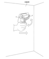
- FIG. FIG. 1 is a perspective view showing a configuration example and usage example of a measuring device according to the present embodiment.
- FIG. 2 is a conceptual diagram of a learning model according to the present embodiment.
- FIG. 2 is a conceptual diagram of an object DB according to the present embodiment. It is a flowchart which shows the processing procedure of the information processing device system concerning this embodiment.
- 2 is a flowchart showing a procedure for creating a three-dimensional space model.
- 2 is a flowchart showing a procedure for creating a three-dimensional space model.
- FIG. 2 is an explanatory diagram showing an example of a three-dimensional point group and a photographed image.
- FIG. 1 is a block diagram illustrating a configuration example of an information processing system according to an embodiment.
- FIG. FIG. 1 is a perspective view showing a configuration example and usage example of a measuring device according to the present embodiment.
- FIG. 2 is an explanatory diagram showing an example of a three-dimensional space model. It is a conceptual diagram which shows the concealment process of a concealment target object.
- FIG. 3 is a conceptual diagram illustrating duplicate object exclusion processing. 3 is a flowchart illustrating an object editing process procedure.
- FIG. 3 is a conceptual diagram showing a method of changing an object.
- FIG. 3 is a conceptual diagram showing a method of changing an object.
- FIG. 3 is a conceptual diagram showing a method of changing an object.
- FIG. 3 is a conceptual diagram showing a method of changing an object.
- FIG. 3 is a conceptual diagram showing a method for adding an object.
- FIG. 3 is a conceptual diagram showing a method for adding an object.
- FIG. 3 is a conceptual diagram showing a method for adding an object.
- FIG. 3 is a conceptual diagram showing a method for adding an object.
- FIG. 3 is a conceptual diagram showing a method for adding an object.
- FIG. 2 is a conceptual diagram showing a method for editing a plane that constitutes a target space.
- FIG. 2 is a conceptual diagram showing a method for editing a plane that constitutes a target space.
- FIG. 2 is a conceptual diagram showing a method for editing a plane that constitutes a target space.
- Air conditioning related equipment and an air conditioning system will be described below with reference to the drawings.
- the outline of this embodiment is as follows.
- we analyze the airflow under the conditions of the actual property to identify the air environment, such as temperature irregularities and stagnation, that may actually be occurring at the customer's property.
- After clarifying the problem it becomes possible to propose equipment.
- An example of a system is to take pictures while walking in a space using a handheld depth camera, camera, thermography, and smartphone integrated module, and save depth images and images of the space on a smartphone.
- the data stored in the smartphone is transferred to the information processing device 1, and three-dimensional point cloud data is created using three-dimensional reconstruction software. Detect floors, walls, and ceilings from 3D point cloud data and create a fluid calculation model that is a spatial model of the surface.
- the type and position of the object air conditioner, fixture, etc.
- a cleaning robot, a drone, etc. may be used to take the photos.
- FIG. 1 is a block diagram showing a configuration example of an information processing system according to this embodiment
- FIG. 2 is a perspective view showing a configuration example and usage example of a measuring device 2 according to this embodiment.
- the information processing system according to this embodiment includes an information processing device 1, a measuring device 2, and a terminal device 3.
- the information processing system is one that images and measures a space that has at least a portion of a surface, and semi-automatically creates a three-dimensional space model for predicting the environment of the space based on the data obtained from the measurement. It is.
- the space to be modeled will be referred to as the target space.
- the target space includes one or more objects that can affect the environment of the target space.
- the object includes at least one of an object that affects airflow in the target space, an object that affects the thermal environment of the target space, an object that affects air quality of the target space, and an object that controls the environment of the target space.
- the object includes at least one of fixtures, fittings, people, industrial machinery, plants, air conditioners, and ventilation equipment.
- the fixtures include at least one of a computer, a monitor, a lighting fixture, a heater, and a chair.
- the fittings include at least one of a window, a blind, a partition, and a door.
- Air conditioners include air cleaners.
- the target space has a duct system for ventilation.
- the duct system includes the inlet or outlet of an air conditioner or ventilation device.
- the target space has a piping system for an air conditioner.
- objects include concealed objects that have confidentiality and non-secured objects that do not have confidentiality.
- the objects to be concealed include at least one of a display device, a person, an industrial machine, a document, a destination display board, a bulletin board, a whiteboard, a blackboard, a sticky note, and a piece of mail.
- the measuring device 2 includes an RGB sensor 21, a depth sensor 22, an IR projector 23, an infrared camera 24, a grip section, and a terminal holding section, and is a device that measures physical quantities related to the shape in the target space.
- the gripping section is a member that is gripped by the user of the measuring device 2.
- the gripping portion is, for example, a rod-shaped member.
- the terminal holding section is a member that holds the terminal device 3.
- the RGB sensor 21 is a camera that has an image sensor such as a CMOS sensor or a CCD sensor, and takes a color image of the target space.
- the RGB sensor 21 can shoot moving images.
- the RGB sensor 21 outputs time-series image data (RGB data) obtained by imaging the target space. It is assumed that time-series image data constituting a moving image includes time data indicating the date and time of imaging.
- the depth sensor 22 measures the distance (depth) from the measuring device 2 to the wall of the target space and various objects included in the target space.
- the depth sensor 22 outputs depth data representing the depth obtained by distance measurement.
- the IR projector 23 is an element for projecting infrared rays onto a target space and object in order to obtain more accurate depth data.
- the infrared camera 24 is a camera that has an infrared imaging element and photographs the target space using infrared rays.
- the infrared camera 24 outputs thermography image data obtained by imaging the target space.
- the measuring device 2 configured in this way outputs image data, depth data, and thermography image data to the terminal device 3.
- the measuring device 2 may be configured to output the image data, depth data, and thermography image data to an external portable storage device for storage.
- the measurement device 2 may be configured to directly transmit image data, depth data, and thermography image data to the information processing device 1.
- the image data and depth data will be referred to as target spatial data.
- the terminal device 3 is a portable information processing terminal such as a smartphone, a mobile phone, a tablet terminal, or a PDA (Personal Digital Assistant).
- the terminal device 3 includes an input interface into which image data, depth data, thermography images, and orientation data are input. Further, the terminal device 3 includes an orientation sensor 31.
- the direction sensor 31 is, for example, a direction meter such as an electronic compass, and outputs direction data indicating the direction of the measuring device 2.
- the content of the orientation data is not particularly limited as long as it is information that can specify the orientation of the target space.
- the orientation data may be information based on the latitude, longitude, time, and position of a celestial body in the target space.
- a celestial body is an object existing in space whose position on the celestial sphere is known and can be imaged. Examples of celestial bodies include the sun, the moon, and artificial satellites. If a captured image includes a celestial body whose position on the celestial sphere is known, and the latitude and longitude of the imaged target space and the time of image capture are known, the orientation of the target space can be specified.
- the orientation data may be information based on the latitude and longitude of the target space, the time, the direction of an indoor shadow, and the length of the shadow. Since the position of the sun is specified from the direction of the shadow and the length of the shadow, the direction of the target space can be specified as described above.
- the processing unit 11 of the information processing device 1 can specify the orientation of the target space based on this information.
- the terminal device 3 causes the display device to display the image captured by the measuring device 2 based on the image data input via the input interface.
- the terminal device 3 stores the input image data, depth data, and thermography image, and the orientation data obtained by the orientation sensor 31, and transmits them to the information processing device 1 at an appropriate timing.
- the terminal device 3 may be configured to store the input image data, depth data, and thermography image, and the orientation data obtained by the orientation sensor 31 in a portable storage device.
- the user can grasp the measuring device 2, move within the target space, and direct the measuring device 2 in various directions to measure the walls, floors, etc. of the target space. It is possible to image and measure distances of surfaces, ceiling surfaces, and objects from multiple positions and directions.
- the measuring device 2 provides the information processing device 1 with target space data, thermography image data, and orientation data obtained by measuring the inside of the target space from a plurality of positions.
- the information processing device 1 includes a processing section 11 , a storage section 12 , an acquisition section 13 , a display section 14 , and an operation section 15 .
- the processing unit 11 includes arithmetic circuits such as a CPU (Central Processing Unit), an MPU (Micro-Processing Unit), an ASIC (Application Specific Integrated Circuit), and an FPGA (Field-Programmable Gate Array), a ROM (Read Only Memory), and a RAM ( It is a processor that has an internal storage device such as Random Access Memory (Random Access Memory), I/O terminals, etc.
- the processing unit 11 includes one or more arithmetic circuits such as a GPU (Graphics Processing Unit), a TPU (Tensor Processing Unit), or an AI chip (semiconductor for AI) specialized in image processing related to object detection and image recognition. Good too.
- the processing unit 11 reads and executes a computer program (program product) P stored in the storage unit 12 to create a three-dimensional spatial model of the target space.
- Each functional unit involved in creating a three-dimensional space model may be realized in software, or may be partially or entirely realized in hardware.
- the storage unit 12 is, for example, a hard disk, an EEPROM (Electrically Erasable Programmable ROM), or a flash memory.
- the storage unit 12 stores various programs executed by the processing unit 11 and various data necessary for processing by the processing unit 11.
- the storage unit 12 stores at least a computer program P executed by the processing unit 11, a learning model 16, an air terminal discrimination model 17, and an object DB 18. Details of the learning model 16, the exhaust port discrimination model 17, and the object DB 18 will be described later.
- the computer program P may be written into the storage unit 12 during the manufacturing stage of the information processing device 1, or may be distributed from another information processing device 1 via a network.
- the information processing device 1 acquires the computer program P through communication and writes it into the storage unit 12.
- the computer program P may be readably recorded on a recording medium 10 such as a semiconductor memory such as a flash memory, an optical disk, a magneto-optical disk, or a magnetic disk.
- the information processing device 1 reads out the computer program P and stores it in the storage unit 12 .
- the acquisition unit 13 is a communication circuit that transmits and receives data to and from an external device by wire or wirelessly, or a reading circuit that reads data from a portable storage device.
- the information processing device 1 acquires image data, depth data, thermography image data, orientation data, etc. from the measurement device 2 via the acquisition unit 13.
- the information processing device 1 acquires duct system diagram data representing a duct system related to the inlet or outlet of the ventilation device in the target space from an external device via the acquisition unit 13 .
- the duct system diagram data includes direction information representing the direction of the duct system and external shape information representing the external shape of the duct system.
- the external shape information includes information indicating the position of the inlet or outlet of the air conditioner or ventilation device.
- the information processing device 1 acquires piping system diagram data representing a piping system diagram of the target space from an external device via the acquisition unit 13 .
- the piping system diagram data includes direction information representing the direction of the piping system and external shape information representing the external shape of the piping system.
- the piping system diagram data includes information regarding the position of the indoor unit, thermal boundary conditions of the air conditioner, and the like.
- the information processing device 1 acquires outside temperature time-series data in the target space and sunlight amount time-series data in the target space from an external device via the acquisition unit 13 .
- the display unit 14 is, for example, a display device such as a liquid crystal display panel or an organic EL display panel.
- the processing unit 11 displays an image related to the three-dimensional space model on the display unit 14.
- the operation unit 15 is an input device such as a mouse, a keyboard, or a touch panel that receives operations from a user of the information processing device 1.
- the processing unit 11 accepts editing of the three-dimensional space model by the user via the operation unit 15.
- the information processing device 1 may be a server device connected to a network.
- the information processing device 1 may include a terminal computer and a server device.
- the information processing device 1 may be configured to include multiple computers and perform distributed processing, may be realized by multiple virtual machines provided in one server, or may be realized using a cloud server. You can leave it there.
- the information processing device 1 may be a terminal device 3. That is, the terminal device 3 may be configured to function as the information processing device 1.
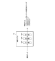
- FIG. 3 is a conceptual diagram of the learning model 16 according to this embodiment.
- the learning model 16 includes, for example, a convolutional neural network (CNN) trained by deep learning.
- the learning model 16 includes an input layer 16a into which image data captured using the measurement device 2 is input, an intermediate layer 16b which extracts feature amounts of the image data, and an output layer which outputs inference results related to detected objects. layer 16c.
- the learning model 16 is, for example, a YOLO model.
- Each layer of the learning model 16 has multiple nodes.
- the nodes in each layer are connected by edges.
- Each layer has an activation function (response function) and edges have weights.
- the value output from the node of each layer is calculated from the value of the node of the previous layer, the edge weight, and the activation function of the layer. Edge weights can be changed through learning.
- the input layer 16a of the learning model 16 has a plurality of nodes that accept input of image data, that is, the pixel value of each pixel constituting the image of the target space and the surface of the object, and the input pixel value is transmitted to the intermediate layer 16b. hand it over to The intermediate layer 16b includes multiple sets of convolutional layers (CONV layers), pooling layers, and fully connected layers.
- CONV layers convolutional layers
- the convolution layer performs filter processing on the values output from the nodes of the previous layer and extracts a feature map.
- the pooling layer reduces the feature map output from the convolution layer to obtain a new feature map.
- the output layer 16c has a node that outputs the final inference result regarding the object detected from the image data.
- the inference results include the center coordinate position and vertical and horizontal size of the bounding box surrounding the object, an object detection score that indicates the certainty that the image surrounded by the bounding box is an image of the object, and the probability that the object belongs to a specific class. Includes class scores etc.
- the output obtained from the output layer 16c includes a plurality of mutually overlapping bounding boxes, but the target space is The position and size of the most likely bounding box surrounding each of one or more objects included in the image, an object detection score, and a class score are obtained.
- training data including a plurality of image data of a target space including an object and an annotation file for each image data is prepared.
- the annotation file is teacher data indicating the correct value given to the corresponding image.
- the annotation file is data indicating the center coordinate position, vertical and horizontal size, and class of a bounding box surrounding the image of the object included in the corresponding image.
- a class indicates a group classified according to the attributes of an object.
- the learning model 16 can be generated by optimizing the weighting coefficients of the neural network using a propagation method, an error gradient descent method, or the like.
- the learning model 16 may also be configured using R-CNN, Fast R-CNN, Faster R-CNN, other CNNs, Vision Transformer, etc. Good too.
- a learning model 16 using an algorithm such as a decision tree, random forest, or SVM (Support Vector Machine) may be used.
- the learning model 16 may be configured by combining the plurality of algorithms described above.
- the air terminal discrimination model 17 is an image recognition learning model that discriminates whether the air terminal is an inlet or an outlet based on image data of the air terminal of an air conditioner or ventilation device.
- the air outlet discrimination model 17 includes, for example, a convolutional neural network (CNN) trained by deep learning. The configuration of the neural network itself is similar to the learning model 16.
- the air terminal discrimination model 17 includes an input layer into which air terminal image data, which is data of an image portion of an air conditioner or a ventilation system (hereinafter referred to as air terminal image), is input, and It has an intermediate layer that extracts feature amounts of image data, and an output layer that outputs accuracy data indicating the accuracy with which an air terminal image corresponds to an inlet or an outlet.
- the method for generating the air vent discrimination model 17 will be explained. First, training data including a plurality of air terminal image data and teacher data indicating whether each air terminal image corresponds to an inlet or an outlet is prepared. Then, when the training data terminal image is input to the CNN, the processing unit 11 generates an error (a predetermined loss function or error function) between the data output from the CNN and the data indicated by the teacher data.
- the air terminal discriminating model 17 can be generated by optimizing the weighting coefficients of the neural network using error backpropagation, error gradient descent, or the like so that the value (value) becomes small.
- the learning model 16 may be used to discriminate between the inlet and the outlet.
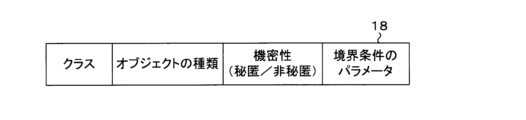
- FIG. 4 is a conceptual diagram of the object DB 18 according to this embodiment.
- the object DB 18 stores, for example, object classes, object types, confidentiality, boundary condition types, and boundary condition parameters in association with each other.
- Types of objects include the above-mentioned fixtures, fittings, people, industrial machines, plants, air conditioners, ventilation equipment, and the like.
- Confidentiality is data indicating whether an object is a concealed object or a non-secured object.
- the boundary condition parameters are, for example, data indicating Dirichlet boundary conditions, Neumann boundary conditions, etc. of temperature, pressure, and flow velocity on the object surface.
- the parameters include, for example, sensible heat, latent heat, air volume, wind direction, and wind speed.
- the environmental condition parameters are an example of influence regulation data that defines the influence of the concealed object on the environment of the target space.
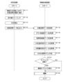
- FIG. 5 is a flowchart showing the processing procedure of the information processing device 1 system according to the present embodiment.
- the measuring device 2 is moved or rotated within the target space by the user to image and measure the distance of the target space (step S111).
- the infrared camera 24 images the target space using infrared light (step S112).
- the orientation sensor 31 detects the orientation of the measuring device 2 (step S113).
- the terminal device 3 transmits the target space data, thermography image data, and orientation data to the information processing device 1 (step S114).
- the processing unit 11 of the information processing device 1 acquires the target space data, thermography image data, and orientation data output from the terminal device 3 (step S115).
- the processing unit 11 may convert it into data that directly represents the orientation through arithmetic processing. For example, the processing unit 11 calculates data indicating the orientation based on the latitude, longitude, time, and position of the celestial body in the target space. For example, the processing unit 11 calculates data indicating the direction based on the latitude and longitude of the target space, the time, the direction of the indoor shadow, and the length of the shadow. Note that the processing unit 11 may calculate data indicating the orientation of the three-dimensional space based on the image data and time data.
- the processing unit 11 acquires duct system diagram data from an external device (step S116), and acquires piping system diagram data (step S117).
- the processing unit 11 acquires outside temperature time series data from an external device (step S118).
- the processing unit 11 acquires sunlight amount time series data from an external device (step S119).
- a sensor provided around the target space detects the outside temperature and the amount of sunlight, and transmits the outside temperature time series data and the amount of sunlight time series data to the information processing device 1 .
- the processing unit 11 acquires outside temperature time series data and sunshine amount time series data from the sensor.
- the processing unit 11 may be configured to acquire weather information such as outside temperature time series data and sunshine amount time series data from an external server that distributes these data.
- the processing unit 11 creates a three-dimensional space model that reflects the influence of the object on the target space, based on various data such as the acquired target space data (step S120).
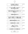
- FIG. 8 is an explanatory diagram showing an example of a three-dimensional point group and a captured image
- FIG. 9 is an explanatory diagram showing an example of a three-dimensional spatial model.
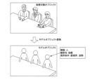
- 10A and 10B are conceptual diagrams showing the concealment processing of the concealment target object.
- the outline of the process is as follows.
- image data and depth data are analyzed to create 3D point cloud data of the target space, and heat sources, etc. that need to be considered when performing fluid analysis are created.
- the pre-trained learning model 16 for the elements, the type and position in the three-dimensional point cloud data are identified from the photographed image, and reflected in the three-dimensional space model.
- the processing unit 11 of the information processing device 1 restores a three-dimensional point group in the target space based on the image data and depth data (step S131).
- the upper diagram shows image data and depth data
- the lower left diagram shows three-dimensional point group data.
- the lower right figure shows image data corresponding to the three-dimensional point group data.
- the processing unit 11 creates a three-dimensional space model for fluid calculation based on the three-dimensional point group data using the self-position estimation technique and the line-of-sight direction estimation technique (step S132).
- the processing unit 11 uses self-position estimation technology and line-of-sight direction estimation technology to estimate planes corresponding to walls, floors, and ceilings of the target space, planes corresponding to external surfaces of objects such as various equipment and fixtures, and planes of each plane.
- a three-dimensional space model consisting of multiple planes can be created with the ability to specify the location.
- the processing unit 11 By inputting image data into the learning model 16, the processing unit 11 detects objects (non-concealed objects and concealed objects) and recognizes the position and class of the objects, as shown in the lower right diagram of FIG. (Step S133). Furthermore, the processing unit 11 recognizes the dimensions of the object. By referring to the object DB 18 using the class as a key, the processing unit 11 recognizes whether the detected object is a concealed object. If the image data of the object includes information such as characters, symbols, etc. related to thermal boundary conditions, the processing unit 11 reads the information such as characters and obtains information related to attributes of the object and thermal boundary conditions. It may be configured to do so.
- the processing unit 11 identifies the boundary conditions of the non-concealed object and the concealed object based on the object recognition result (step S134). Specifically, the processing unit 11 specifies the value of the boundary condition by reading the parameters of the boundary condition corresponding to the classes of the non-concealed object and the concealed object.
- the processing unit 11 adds boundary conditions for the non-concealed object and the concealed object to the three-dimensional space model (step S135).
- the position where the boundary condition is set in the three-dimensional space is specified based on the position and dimensions of the object recognized in step S132 and the three-dimensional point group.
- the processing unit 11 may be configured to apply the human thermal boundary condition to the chair object.
- the storage unit 12 of the information processing device 1 stores typical predetermined thermal boundary conditions of a human object, such as sensible heat and latent heat, and the processing unit 11 preferably applies the thermal boundary conditions to the chair object. .
- the processing unit 11 identifies the temperature, amount of heat, or temperature characteristics of the non-concealed object and the concealed object based on the thermography image data, and assigns a heat generation condition to the object (step S136).
- thermography By using the heat content of objects such as fixtures, it is possible to analyze the environment of the target space in more detail. Therefore, by measuring using thermography, the temperature or heat amount of the object is calculated and reflected in the fluid calculation model.
- the object to be concealed included in the three-dimensional space model is replaced with a model object that does not contain confidential information (step S137).
- the shape of the model object may be a substantially rectangular parallelepiped object surrounding the object to be concealed, or may be an object having a shape corresponding to the object to be concealed.
- the storage unit 12 may be configured to store model objects in association with classes of objects to be concealed.
- the processing unit 11 reads a model object corresponding to the class of the object to be concealed, and replaces the object to be concealed with the read model object.
- a method of replacing a concealed object with a model object is an example of a method of concealing a concealed object.
- the object to be concealed may be configured to be processed by any method.
- the computer and timing for concealing the concealed object are not particularly limited.
- the processing may be executed by the terminal computer or by the server device.
- the terminal device 3 may be configured to execute processing for concealing the concealed object.
- the processing unit 11 inputs image data of the air terminal of the air conditioner or ventilation system into the air terminal discrimination model 17 to determine whether the air terminal is an inlet or an outlet (step S138).
- step S138 an example was explained in which the inlet and the outlet are determined using the machine learning model, but the feature values related to the inlet and the outlet are calculated based on the image data of the air outlet.
- the configuration may be such that it is determined whether the air terminal is an inlet or an outlet based on the characteristic amount determined.
- processing unit 11 is able to determine the inlet and outlet with sufficient accuracy through the image recognition process in step S133 using the learning model 16, the processing in steps S138 to S141 may be omitted.
- the processing unit 11 generates a target space represented by the target space data based on orientation data related to the acquired orientation of the target space, information representing the outer shape of the target space based on the target space data, and duct system diagram data. and the duct system represented by the duct system data (step S139).
- the target space and the duct system may be aligned with each other based on the positions of elevators, stairs, pillars, etc. whose exact positions are objectively known and unchangeable.
- the processing unit 11 determines whether the air terminal is an inlet or an outlet based on the acquired duct system diagram data (step S140).
- step S140 the duct type suction inlet and outlet, which is information that is difficult to determine by image recognition, is determined using the duct system diagram.
- the inlet and outlet of a duct-type air conditioner or ventilation system the fluid calculation results differ greatly depending on whether it is an inlet or an outlet, so it is necessary to correctly distinguish between them, but there is a big difference in their appearance. Because there is no such thing, it is difficult to determine whether it is an inlet or an outlet using image recognition alone. Therefore, by acquiring information about the inlet and outlet from the duct system diagram in the target space, it is reflected in the three-dimensional space model.
- step S140 by using the duct system diagram when creating the three-dimensional space model, the duct system of the air conditioner or ventilation system can be recognized and the setting of thermal boundary conditions of the inlet and outlet can be supported. I can do it.
- the processing unit 11 determines whether the air terminal is an inlet or an outlet, based on the thermography image data that includes the air terminal (step S141).
- the inlet and outlet are determined by measuring the temperature of the inlet and outlet of the air conditioner or ventilation device and the temperature of the ceiling surface using a thermography image, and Reflect thermal boundary conditions in the 3D spatial model.
- the processing unit 11 acquires orientation data related to the orientation of the target space, and generates the target space data based on the acquired orientation data, information representing the outer shape of the target space based on the target space data, and piping system diagram data.
- the target space represented by is aligned with the piping system represented by the piping system diagram data (step S142).
- Thermal boundary conditions of the air conditioner based on the acquired piping system diagram data are given to the three-dimensional space model (step S143). Since the piping system of the air conditioner and the target space have been aligned, the processing unit 11 can specify the relationship between the piping system and the air conditioner object included in the target space. The processing unit 11 can specify information related to the thermal boundary conditions of the piping system corresponding to the object of the air conditioner, and can add the thermal boundary conditions of the object to the three-dimensional space model.
- air conditioner system information is important when performing airflow analysis.
- sufficient information about the air conditioner cannot be obtained only through object image recognition. Therefore, by using piping system diagram data, indoor unit system information can be reflected in the three-dimensional space model. Note that the piping system diagram may be displayed superimposed on the three-dimensional space model.
- the processing unit 11 calculates the heat transmission coefficient of the fittings based on the thermography image data, the outside temperature time series data of the target space, the sunlight amount time series data, and the thickness data of the fittings (step S144).
- the processing unit 11 applies the calculated thermal transmission coefficient as a thermal boundary condition of the fittings (step S145).
- the thickness of the fittings is obtained by the image recognition process in step S133.
- the processing unit 11 may be configured to calculate the thickness of the fitting by combining the image recognition processing result in step S133 and the data of the three-dimensional point group.
- step S144 and S145 the heat transfer coefficient of the fittings is calculated by measuring using thermography, and reflected in the three-dimensional space model.
- step S144 and step S145 by using the thermography image, outside temperature time series data, and solar radiation time series data, the thermal conductivity of fittings such as walls and windows is calculated, and the input of thermal boundary conditions is supported. can do.
- the processing unit 11 identifies the usage scene of the target space based on the image data (step S146), and adds usage scene data indicating the identified usage scene of the target space to the three-dimensional space data (step S147). For example, attributes are added to three-dimensional spatial data tailored to scenes such as hospitals, schools, factories, and offices.
- the processing unit 11 may identify an underfloor outlet included in the target space based on the image data, and may add data indicating the position of the underfloor outlet to the three-dimensional space data.
- the processing unit 11 adds the acquired orientation data or information based on the orientation data to the three-dimensional space model (step S148), and ends the three-dimensional space model creation process. For example, data indicating the orientation of the three-dimensional space model is added to the three-dimensional space model.
- the processing unit 11 determines whether the target spatial data includes duplicate objects (step S121). For example, if the similarity in shape and attribute of the plurality of objects is greater than or equal to a predetermined value and the distance between the plurality of objects is less than the predetermined distance, the processing unit 11 determines the plurality of objects to be overlapping objects.
- FIG. 11 is a conceptual diagram showing the process of excluding duplicate objects. If the objects are duplicated (step S121: YES), the processing unit 11 excludes the duplicate objects, as shown in FIG. 11 (step S122).
- step S122 After completing the process of step S122, if it is determined that the objects do not overlap (step S121: NO), the processing unit 11 executes a three-dimensional space model editing process (step S123).
- FIG. 12 is a flowchart showing the object editing processing procedure.
- the processing unit 11 superimposes a three-dimensional point group on the created three-dimensional space model and displays it on the display unit 14 (step S151).
- the processing unit 11 receives changes to the object via the operation unit 15 (step S152), and changes the object according to the received operation (step S153). For example, the processing unit 11 accepts and changes the shape, class, and boundary condition parameters of the object.
- the three-dimensional space model changes when people move or gather in the target space.
- the processing unit 11 receives changes in the number and position of human objects in the target space, and changes the number and position of human objects.
- the processing unit 11 acquires data related to the seating arrangement diagram of the target space, and applies thermal boundary conditions of a person to the seat object based on the acquired data and information representing the outer shape of the target space based on the target space data. It may be configured to give the following.
- the seat layout map is data indicating the position of a seat object in the target space.
- the processing unit 11 applies thermal boundary conditions of the human object to the object of the seat based on the target space represented by the target space data and the position of the seat object represented by the data related to the seating layout map. do.
- the storage unit 12 of the information processing device 1 stores typical predetermined thermal boundary conditions for human objects, and the processing unit 11 preferably applies the thermal boundary conditions to the seat object.
- FIGS. 13A, 13B, and 13C are conceptual diagrams showing a method for changing an object.
- FIG. 13A shows a three-dimensional spatial model of the target space including recognized objects.
- FIG. 13B shows a state in which an object to be edited is selected, and
- FIG. 13C shows a state in which the shape of the object has been changed.
- the processing unit 11 accepts the addition of an object via the operation unit 15 (step S154), and adds the object according to the received operation (step S155).
- FIGS. 14A, 14B, and 14C are conceptual diagrams showing a method for adding objects.
- FIG. 14A shows a three-dimensional spatial model of the target space in which no objects actually existing are recognized.
- FIG. 14B shows a state in which an object addition operation is being performed, and
- FIG. 14C shows a state in which an object has been added.
- the processing unit 11 accepts changes and additions to the plane of the three-dimensional space via the operation unit 15 (step S156), and changes or adds the plane of the three-dimensional space according to the received operation (step S157).
- the plane is a portion corresponding to a wall surface or the like in the target space.
- FIGS. 15A, 15B, and 15C are conceptual diagrams showing a method for editing a plane that constitutes a target space.
- FIG. 15A shows a three-dimensional spatial model of the target space in which wall planes that actually exist are not recognized.
- FIG. 15B shows a state in which a wall plane addition operation is being performed, and
- FIG. 15C shows a state in which a wall plane has been added.
- the processing unit 11 performs processing similar to step S132 and step S133 at any timing in the processing steps described above to obtain parameters such as the dimensions, shape, sensible heat, latent heat, air volume, wind direction, wind speed, and boundary conditions of the object.
- the attributes of the object may be specified, and an augmented reality image may be created in which the identified attributes of the object are reflected in the image data.
- the processing unit 11 adds data for superimposing and displaying an image representing an attribute of an object included in the image to image data obtained by imaging the target space with the measuring device 2. Any display device that reproduces image data of a target space can reproduce an augmented reality video by reproducing an augmented reality image.
- the influence of objects included in the target space on the environment of the target space is reflected based on target space data obtained by measuring the inside of the target space from a plurality of positions. It is possible to create a three-dimensional spatial model based on the It is possible to reduce the number of man-hours required to create a three-dimensional space model, which is a model for fluid calculations (indoor model, element models such as fixtures and heat sources). There is no need to measure the room shape and fixtures, and measurement errors are eliminated.
- thermography image it is possible to create a three-dimensional spatial model with boundary conditions that take into account differences in the suction or outlet.
- thermography images etc., it is possible to create a three-dimensional spatial model that gives the heat transmission coefficient of fittings such as walls and windows.
- the target space and objects included in the three-dimensional space model can be edited and changed through user operations.
- Wall planes and objects in the target space can be added to the three-dimensional space model through user operations.
- a three-dimensional space model can be created in which the concealed object is replaced with a model object.
Landscapes
- Engineering & Computer Science (AREA)
- Physics & Mathematics (AREA)
- Theoretical Computer Science (AREA)
- General Physics & Mathematics (AREA)
- Computer Hardware Design (AREA)
- General Engineering & Computer Science (AREA)
- Geometry (AREA)
- Multimedia (AREA)
- Evolutionary Computation (AREA)
- Software Systems (AREA)
- Computer Vision & Pattern Recognition (AREA)
- Computer Graphics (AREA)
- Mathematical Analysis (AREA)
- Mathematical Optimization (AREA)
- Pure & Applied Mathematics (AREA)
- Computing Systems (AREA)
- Architecture (AREA)
- Human Computer Interaction (AREA)
- Computational Mathematics (AREA)
- Artificial Intelligence (AREA)
- Mathematical Physics (AREA)
- Medical Informatics (AREA)
- Fluid Mechanics (AREA)
- Algebra (AREA)
- Image Analysis (AREA)
- Processing Or Creating Images (AREA)
Abstract
Description
特許文献2は、3次元点群データと画像を組み合わせたデータベースを作成し、このデータベースと対象物を撮影した画像のマッチングにより対象物の位置を特定する技術を開示する。
顧客の物件へ訪問し、空調関連の営業活動を行う際、実際の物件の条件における気流解析を行うことにより、実際に顧客物件で発生していると考えられる温度ムラや淀みなどの空気環境の問題を明らかにしたうえで機器の提案が可能となる。しかし、実際に気流解析を行うための流体計算用モデルを作成する場合、室内形状や什器の採寸及びモデル化、熱源などの条件の設定に多くの時間がかかっている。
上記課題を解決する手段として、流体計算用モデル自動作成手法を提案する。システム例としては、手持ちのデプスカメラ、カメラ、サーモグラフィー、スマートフォン一体型モジュールを用いて空間内を歩行しながら撮影し、空間内のデプス画像、画像をスマートフォンに保存する。スマートフォンに保存したデータを情報処理装置1へ転送し、3次元再構成用のソフトを用いて3次元点群データを作成する。3次元点群データから床、壁、天井を検出し、面の空間モデルである流体計算用モデルを作成する。ここで、撮影画像に対して事前に機械学習により学習した画像認識を行うことによってオブジェクトの種類(空調機、什器等)と位置を特定し、3次元空間モデルに反映する。人が手持ちで撮影する代わりにお掃除ロボットやドローンなどを用いて撮影しても良い。
方位データは、対象空間の緯度、経度、時刻、屋内の影の向き及び影の長さに基づく情報であってもよい。影の向き及び影の長さから太陽の位置が特定されるため、上記同様、対象空間の方位を特定することができる。
情報処理装置1の処理部11は、これらの情報に基づいて、対象空間の方位を特定することができる。
情報処理装置1は、処理部11、記憶部12、取得部13、表示部14及び操作部15を備える。
処理部11は、CPU(Central Processing Unit)、MPU(Micro-Processing Unit)、ASIC(Application Specific Integrated Circuit)、FPGA(Field-Programmable Gate Array)などの演算回路、ROM(Read Only Memory)、RAM(Random Access Memory)などの内部記憶装置、I/O端子などを有するプロセッサである。処理部11は、物体検出及び画像認識に係る画像処理に特化したGPU(Graphics Processing Unit)、TPU(Tensor Processing Unit)又はAIチップ(AI用半導体)などの1又は複数の演算回路を備えてもよい。処理部11は、記憶部12に記憶されたコンピュータプログラム(プログラム製品)Pを読み出して実行することにより、対象空間の3次元空間モデルを作成する。3次元空間モデルの作成に係る各機能部は、ソフトウェア的に実現してもよいし、一部又は全部をハードウェア的に実現してもよい。
情報処理装置1は、取得部13を介して、対象空間における換気装置の吸込口又は吹出口に関連するダクト系統を表したダクト系統図データを外部装置から取得する。ダクト系統図データは、ダクト系統の方向を表す方向情報と、ダクト系統の外形を示す外形情報とを含む。外形情報には、空調機又は換気装置の吸込口又は吹出口の位置を示す情報が含まれている。
情報処理装置1は、取得部13を介して、対象空間の配管系統図を表した配管系統図データを外部装置から取得する。配管系統図データは、配管系統の方向を表す方向情報と、配管系統の外形を示す外形情報とを含む。配管系統図データは、室内機の位置、空調機の熱境界条件に係る情報等を含む。
情報処理装置1は、取得部13を介して、対象空間の外気温時系列データ、対象空間における日照量時系列データを外部装置から取得する。
図3は、本実施形態に係る学習モデル16の概念図である。学習モデル16は、例えば深層学習による学習済みの畳み込みニューラルネットワーク(CNN:Convolutional neural network)を含む。学習モデル16は、測定装置2を用いて撮像された画像データが入力される入力層16aと、画像データの特徴量を抽出する中間層16bと、検出されたオブジェクトに係る推論結果を出力する出力層16cとを有する。学習モデル16は、例えばYOLOモデルである。
中間層16bは、複数組みの畳み込み層(CONV層)及びプーリング層と、全結合層とを有する。畳み込み層は、前層のノードから出力された値に対してフィルタ処理を実行し、特徴マップを抽出する。プーリング層は、畳み込み層から出力された特徴マップを縮小して新たな特徴マップを得る。
図4は、本実施形態に係るオブジェクトDB18の概念図である。オブジェクトDB18は、例えば、オブジェクトのクラスと、オブジェクトの種類と、機密性と、境界条件の種類と、境界条件のパラメータとを対応付けて記憶している。オブジェクトの種類は、上記した什器、建具、人、産業機械、植物、空調機、換気装置等が含まれる。機密性は、オブジェクトが秘匿対象オブジェクトであるか、非秘匿対象オブジェクトであるかを示すデータである。境界条件のパラメータは、例えば、オブジェクト表面における温度、圧力、流速のディリクレ境界条件、ノイマン境界条件等を示すデータである。パラメータは、例えば、顕熱、潜熱、風量、風向、風速等を含む。
図5は、本実施形態に係る情報処理装置1システムの処理手順を示すフローチャートである。使用者によって測定装置2は対象空間内を移動又は回転し、対象空間を撮像及び測距する(ステップS111)。赤外線カメラ24は対象空間を赤外線にて撮像する(ステップS112)。方位センサ31は測定装置2の方位を検出する(ステップS113)。
例えば、処理部11は、対象空間の緯度、経度、時刻及び天体の位置に基づいて、方位を示すデータを算出する。
例えば、処理部11は、対象空間の緯度、経度、時刻、屋内の影の向き及び影の長さに基づいて、方位を示すデータを算出する。
なお、処理部11は、画像データ及び時間データに基づいて、3次元空間の方位を示すデータを算出してもよい。
例えば、対象空間の周辺に設けられたセンサが外気温時及び日照量を検出し、外気温時系列データ及び日照量時系列データを情報処理装置1へ送信する。処理部11は、当該センサから外気温時系列データ及び日照量時系列データを取得する。
なお、処理部11は、外気温時系列データ及び日照量時系列データ等の気象情報を配信する外部サーバからこれらのデータを取得するように構成してもよい。
図6及び図7は、3次元空間モデルの作成処理手順を示すフローチャート、図8は、3次元点群及び撮影画像の一例を示す説明図、図9は、3次元空間モデルの一例を示す説明図、図10は、秘匿対象オブジェクトの秘匿化処理を示す概念図である。
秘匿対象オブジェクトを秘匿化するコンピュータ及びタイミングは特に限定されるものでは無い。情報処理装置1が端末コンピュータと、サーバ装置とで構成されている場合、端末コンピュータで実行してもよいし、サーバ装置で実行してもよい。端末装置3が秘匿対象オブジェクトを秘匿化する処理を実行するように構成してもよい。
処理部11は、空調機又は換気装置の制気口の画像データを、制気口判別モデル17に入力することによって、制気口が吸込口及び吹出口のいずれであるかを判別する(ステップS138)。
ダクト式の空調機又は換気装置の吸込口及び吹出口に関しては、吸込口か吹出口かによって流体計算の結果が大きく異なるため、これらを正しく判別する必要があるが、これらの見た目に大きな違いが無いため、画像認識のみでは吸込口か吹出口を判別することが難しい。そこで、対象空間におけるダクト系統図から吸込口及び吹出口の情報を取得することにより、3次元空間モデルに反映する。
ステップS144及びステップS145によれば、サーモグラフィ画像と、外気温時系列データ及び日射量時系列データを用いることで、壁、窓等の建具の熱貫流率を算出し、熱境界条件の入力を支援することができる。
本実施形態に係る情報処理装置1等によれば、対象空間内を複数の位置から測定して得られる対象空間データに基づいて、対象空間に含まれるオブジェクトが対象空間の環境に及ぼす影響を反映させた3次元空間モデルを作成することができる。
流体計算用モデル(室内モデル、什器や熱源などの要素モデル)である3次元空間モデルの作成工数を削減することができる。室内形状及び什器の採寸作業が無くなり、採寸誤差が無くなる。
2 測定装置
3 端末装置
11 処理部
12 記憶部
13 取得部
14 表示部
15 操作部
16 学習モデル
17 制気口判別モデル
18 オブジェクトDB
21 RGBセンサ
22 深度センサ
23 IR投射器
24 赤外線カメラ
31 方位センサ
P コンピュータプログラム
Claims (32)
- 対象空間内を複数の位置から測定して得られる対象空間データを取得する取得部と、
取得したデータを処理する処理部とを備え、
前記処理部は、
取得した前記対象空間データから、前記対象空間の環境に影響を及ぼす前記対象空間のオブジェクトの属性及び位置を認識し、
前記対象空間データに、前記対象空間のオブジェクトの属性及び位置を関連付けて出力する
情報処理装置。 - 前記取得部が取得した前記対象空間データと、前記対象空間のオブジェクトの属性及び位置とに基づいて、前記対象空間の環境に影響を及ぼす前記対象空間のオブジェクトの属性及び位置を反映した、前記対象空間の拡張現実映像を作成する
請求項1に記載の情報処理装置。 - 前記取得部が取得した前記対象空間データと、前記対象空間のオブジェクトの属性及び位置とに基づいて、前記対象空間の環境に影響を及ぼす前記対象空間のオブジェクトの属性及び位置を反映した、前記対象空間の3次元空間モデルを作成する
請求項1又は請求項2に記載の情報処理装置。 - 前記3次元空間モデルは前記対象空間の環境を予測するためのモデルである
請求項3に記載の情報処理装置。 - 前記対象空間のオブジェクトは、
対象空間の気流に影響を及ぼすオブジェクトと、
対象空間の熱環境に影響を及ぼすオブジェクトと、
対象空間の空気質に影響を及ぼすオブジェクトと、
対象空間の環境を制御するオブジェクトと
の少なくとも一つを含む請求項1から請求項4のいずれか1項に記載の情報処理装置。 - 前記対象空間のオブジェクトは、
什器と、建具と、
人と、産業機械と、植物と、
空調機と、換気装置と
の少なくとも一つを含む請求項1から請求項5のいずれか1項に記載の情報処理装置。 - 前記対象空間のオブジェクトは空調機又は換気装置を含み、
前記処理部は前記空調機又は前記換気装置の制気口を認識して、前記制気口が吸込口であるか吹出口であるかを判別する
請求項1から請求項6のいずれか1項に記載の情報処理装置。 - 前記処理部は、
前記対象空間における前記吸込口又は前記吹出口に関連するダクト系統を表したダクト系統データを取得し、
取得した前記ダクト系統データに基づいて、前記対象空間における前記吸込口又は前記吹出口を判別する
請求項7に記載の情報処理装置。 - 前記ダクト系統データは、前記ダクト系統の方位及び外形を示す方位情報及び外形情報を含み、
前記処理部は、
前記対象空間の方位に関連する方位情報を取得し、取得した前記方位情報と、前記対象空間データに基づく前記対象空間の外形を表す情報と、前記ダクト系統データとに基づいて、前記対象空間データによって表される前記対象空間と、前記ダクト系統データによって表される前記ダクト系統との位置合わせを行う
請求項8に記載の情報処理装置。 - 前記処理部は、
前記対象空間のサーモグラフィデータを取得し、
取得したサーモグラフィデータに基づいて、前記吸込口又は前記吹出口を判別する
請求項7から請求項9のいずれか1項に記載の情報処理装置。 - 前記対象空間データは前記対象空間の画像データを含み、
前記処理部は、
取得した前記画像データに基づいて、前記吸込口又は前記吹出口に関連する特徴量を算出し、算出された前記特徴量に基づいて前記吸込口又は前記吹出口を判別する
請求項7から請求項10のいずれか1項に記載の情報処理装置。 - 前記対象空間のオブジェクトの属性は、前記対象空間のオブジェクトの寸法と、形状と、顕熱と、潜熱と、風量と、風向と、風速との少なくとも一つを含む
請求項1から請求項11のいずれか1項に記載の情報処理装置。 - 前記処理部は、
前記対象空間のオブジェクトの属性に応じた熱境界条件を含む3次元空間モデルを作成する
請求項1から請求項12のいずれか1項に記載の情報処理装置。 - 前記処理部は、
前記対象空間における空調機の配管系統を表した配管系統データを取得し、
取得した前記配管系統データに基づいて、前記空調機の熱境界条件を含む3次元空間モデルを作成する
請求項1から請求項13のいずれか1項に記載の情報処理装置。 - 前記配管系統データは、前記配管系統の方位及び外形を示す方位情報及び外形情報を含み、
前記処理部は、
前記対象空間の方位に関連する方位情報を取得し、取得した前記方位情報と、前記対象空間データに基づく前記対象空間の外形を表す情報と、前記配管系統データとに基づいて、前記対象空間データによって表される前記対象空間と、前記配管系統データによって表される前記配管系統との位置合わせを行う
請求項14に記載の情報処理装置。 - 前記処理部は、
前記対象空間のサーモグラフィデータを取得し、取得したサーモグラフィデータに基づいて、前記オブジェクトの温度を熱境界条件として含む3次元空間モデルを作成する
請求項1から請求項15のいずれか1項に記載の情報処理装置。 - 前記処理部は、
前記対象空間のサーモグラフィデータ、前記対象空間の外気温データ、日照量データ、及び建具の厚みデータを取得し、取得した各データに基づいて、前記建具の熱貫流率を熱境界条件として含む3次元空間モデルを作成する
請求項1から請求項16のいずれか1項に記載の情報処理装置。 - 前記処理部は、
前記対象空間のオブジェクトの属性及び位置の編集を受け付け、3次元空間モデルを変更する
請求項1から請求項17のいずれか1項に記載の情報処理装置。 - 前記処理部は、
前記対象空間のオブジェクトの追加を受け付け、3次元空間モデルを変更する
請求項1から請求項18のいずれか1項に記載の情報処理装置。 - 前記取得部は、
前記対象空間内の形状に係る物理量を測定する測定装置を移動又は回転させて得た前記対象空間データを取得する
請求項1から請求項19のいずれか1項に記載の情報処理装置。 - 前記処理部は、
自己位置推定処理又は視線方向推定処理により、前記対象空間及び前記対象空間のオブジェクトの位置を特定する
請求項1から請求項20のいずれか1項に記載の情報処理装置。 - 前記取得部は、
前記対象空間の方位に関連する方位情報を取得し、
前記処理部は、
前記取得部が取得した前記方位情報、又は前記方位情報に基づく情報を含む3次元空間モデルを作成する
請求項1から請求項21のいずれか1項に記載の情報処理装置。 - 前記方位情報は、
前記対象空間の緯度、経度、時刻及び天体の位置に基づく情報、又は前記対象空間の緯度、経度、時刻、屋内の影の向き及び影の長さに基づく情報である
請求項22に記載の情報処理装置。 - 前記対象空間データは、RGBデータ及び時間データを含み、
前記処理部は、
前記RGBデータ及び前記時間データに基づいて、前記対象空間の方位を特定し、
特定された方位を示す方位情報、又は前記方位情報に基づく情報を含む3次元空間モデルを作成する
請求項1から請求項23のいずれか1項に記載の情報処理装置。 - 前記対象空間データは、RGBデータ及び時間データを含み、
前記処理部は、
前記RGBデータ及び前記時間データに基づいて、前記対象空間の利用シーンを特定する
請求項1から請求項24のいずれか1項に記載の情報処理装置。 - 前記処理部は、前記対象空間データが前記対象空間のオブジェクトを重複して含んでいるかどうかを判別する
請求項1から請求項25のいずれか1項に記載の情報処理装置。 - 前記処理部は、
前記対象空間に含まれる前記オブジェクトを重複して認識した場合、重複する前記オブジェクトを除外する
請求項1から請求項26のいずれか1項に記載の情報処理装置。 - 前記取得部が取得した前記対象空間データに基づいて、前記対象空間の秘匿対象オブジェクトの属性及び位置を認識し、
前記取得部が取得した前記対象空間データと、前記対象空間における前記オブジェクトの属性及び位置と、前記対象空間における前記秘匿対象オブジェクトの属性及び位置とに基づいて、前記対象空間の環境に対する前記オブジェクト及び前記秘匿対象オブジェクトの前記属性及び位置を反映した、前記対象空間の3次元空間モデルを作成し、
前記秘匿対象オブジェクトを加工する
請求項1から請求項27のいずれか1項に記載の情報処理装置。 - 請求項1から請求項28のいずれか1項に記載の情報処理装置と、
前記対象空間内の形状に係る物理量を測定する測定装置と
を備え、
前記情報処理装置は、
前記測定装置から前記対象空間データを取得する
情報処理システム。 - 対象空間内を複数の位置から測定して得られる対象空間データを取得する取得部と、取得したデータを処理する処理部とを備え、
前記処理部は、
前記対象空間の環境に影響を及ぼす前記対象空間のオブジェクトの属性及び位置を認識し、
前記対象空間データに、前記対象空間のオブジェクトの属性及び位置を関連付けて出力する
情報処理システム。 - 対象空間内を複数の位置から測定して得られる対象空間データを取得し、
前記対象空間の環境に影響を及ぼす前記対象空間のオブジェクトの属性及び位置を認識し、
前記対象空間データに、前記対象空間のオブジェクトの属性及び位置を関連付けて出力する
情報処理方法。 - 対象空間内を複数の位置から測定して得られる対象空間データを取得し、
前記対象空間の環境に影響を及ぼす前記対象空間のオブジェクトの属性及び位置を認識し、
前記対象空間データに、前記対象空間のオブジェクトの属性及び位置を関連付けて出力する
処理をコンピュータに実行させるためのコンピュータプログラム。
Priority Applications (4)
| Application Number | Priority Date | Filing Date | Title |
|---|---|---|---|
| EP23857371.1A EP4579602A4 (en) | 2022-08-23 | 2023-08-23 | INFORMATION PROCESSING DEVICE, INFORMATION PROCESSING SYSTEM, INFORMATION PROCESSING METHOD AND COMPUTER PROGRAM |
| CN202380060203.7A CN119731702A (zh) | 2022-08-23 | 2023-08-23 | 信息处理装置、信息处理系统、信息处理方法以及计算机程序 |
| AU2023329569A AU2023329569A1 (en) | 2022-08-23 | 2023-08-23 | Information processing device, information processing system, information processing method, and computer program |
| US19/060,618 US20250191317A1 (en) | 2022-08-23 | 2025-02-21 | Information processing apparatus, information processing system information processing method, and computer program |
Applications Claiming Priority (2)
| Application Number | Priority Date | Filing Date | Title |
|---|---|---|---|
| JP2022-132598 | 2022-08-23 | ||
| JP2022132598 | 2022-08-23 |
Related Child Applications (1)
| Application Number | Title | Priority Date | Filing Date |
|---|---|---|---|
| US19/060,618 Continuation US20250191317A1 (en) | 2022-08-23 | 2025-02-21 | Information processing apparatus, information processing system information processing method, and computer program |
Publications (1)
| Publication Number | Publication Date |
|---|---|
| WO2024043263A1 true WO2024043263A1 (ja) | 2024-02-29 |
Family
ID=90013371
Family Applications (1)
| Application Number | Title | Priority Date | Filing Date |
|---|---|---|---|
| PCT/JP2023/030258 Ceased WO2024043263A1 (ja) | 2022-08-23 | 2023-08-23 | 情報処理装置、情報処理システム、情報処理方法及びコンピュータプログラム |
Country Status (6)
| Country | Link |
|---|---|
| US (1) | US20250191317A1 (ja) |
| EP (1) | EP4579602A4 (ja) |
| JP (1) | JP7502702B2 (ja) |
| CN (1) | CN119731702A (ja) |
| AU (1) | AU2023329569A1 (ja) |
| WO (1) | WO2024043263A1 (ja) |
Cited By (1)
| Publication number | Priority date | Publication date | Assignee | Title |
|---|---|---|---|---|
| JP7717208B1 (ja) | 2024-03-08 | 2025-08-01 | 東芝プラントシステム株式会社 | 配置設計自動化システム、および、配置設計方法 |
Families Citing this family (1)
| Publication number | Priority date | Publication date | Assignee | Title |
|---|---|---|---|---|
| EP4679998A1 (en) | 2024-03-04 | 2026-01-14 | National Institute Of Advanced Industrial Science and Technology | Piezoelectric element and mems device using said piezoelectric element |
Citations (9)
| Publication number | Priority date | Publication date | Assignee | Title |
|---|---|---|---|---|
| JP2003162219A (ja) * | 2001-11-29 | 2003-06-06 | Nti:Kk | 3次元地図情報検索システム |
| US20150084755A1 (en) * | 2013-09-23 | 2015-03-26 | Audi Ag | Driver assistance system for displaying surroundings of a vehicle |
| JP2015148410A (ja) * | 2014-02-07 | 2015-08-20 | 株式会社東芝 | 空調制御装置、空調制御システム、空調制御方法及びプログラム |
| JP2016027480A (ja) * | 2012-04-27 | 2016-02-18 | キヤノンマーケティングジャパン株式会社 | 情報処理システム、情報処理装置、その制御方法、及びプログラム |
| JP2017046196A (ja) * | 2015-08-27 | 2017-03-02 | キヤノン株式会社 | 画像情報生成装置、画像情報生成方法、画像処理システム及びプログラム |
| JP6286902B2 (ja) | 2013-07-10 | 2018-03-07 | 株式会社Ihi | 解析装置及び流体解析手法 |
| JP6610640B2 (ja) | 2016-10-28 | 2019-11-27 | Jfeスチール株式会社 | 位置認識方法およびシステム、ならびに異常判定方法およびシステム |
| CN112507799A (zh) * | 2020-11-13 | 2021-03-16 | 幻蝎科技(武汉)有限公司 | 基于眼动注视点引导的图像识别方法、mr眼镜及介质 |
| WO2022113342A1 (ja) * | 2020-11-30 | 2022-06-02 | マクセル株式会社 | 拡張現実処理システム、情報表示装置、及び拡張現実処理方法 |
Family Cites Families (3)
| Publication number | Priority date | Publication date | Assignee | Title |
|---|---|---|---|---|
| KR101310653B1 (ko) * | 2012-04-05 | 2013-09-24 | 연세대학교 산학협력단 | 열화상 카메라를 이용한 빔(bim)기반 상황 인지 시스템 |
| JP2013246589A (ja) * | 2012-05-24 | 2013-12-09 | Sharp Corp | 空間情報生成装置、空間情報利用システム、空間情報生成方法、制御プログラム、および、記録媒体 |
| JP6348763B2 (ja) * | 2014-04-18 | 2018-06-27 | 日立ジョンソンコントロールズ空調株式会社 | 空気調和機 |
-
2023
- 2023-08-09 JP JP2023130305A patent/JP7502702B2/ja active Active
- 2023-08-23 EP EP23857371.1A patent/EP4579602A4/en active Pending
- 2023-08-23 CN CN202380060203.7A patent/CN119731702A/zh active Pending
- 2023-08-23 WO PCT/JP2023/030258 patent/WO2024043263A1/ja not_active Ceased
- 2023-08-23 AU AU2023329569A patent/AU2023329569A1/en active Pending
-
2025
- 2025-02-21 US US19/060,618 patent/US20250191317A1/en active Pending
Patent Citations (9)
| Publication number | Priority date | Publication date | Assignee | Title |
|---|---|---|---|---|
| JP2003162219A (ja) * | 2001-11-29 | 2003-06-06 | Nti:Kk | 3次元地図情報検索システム |
| JP2016027480A (ja) * | 2012-04-27 | 2016-02-18 | キヤノンマーケティングジャパン株式会社 | 情報処理システム、情報処理装置、その制御方法、及びプログラム |
| JP6286902B2 (ja) | 2013-07-10 | 2018-03-07 | 株式会社Ihi | 解析装置及び流体解析手法 |
| US20150084755A1 (en) * | 2013-09-23 | 2015-03-26 | Audi Ag | Driver assistance system for displaying surroundings of a vehicle |
| JP2015148410A (ja) * | 2014-02-07 | 2015-08-20 | 株式会社東芝 | 空調制御装置、空調制御システム、空調制御方法及びプログラム |
| JP2017046196A (ja) * | 2015-08-27 | 2017-03-02 | キヤノン株式会社 | 画像情報生成装置、画像情報生成方法、画像処理システム及びプログラム |
| JP6610640B2 (ja) | 2016-10-28 | 2019-11-27 | Jfeスチール株式会社 | 位置認識方法およびシステム、ならびに異常判定方法およびシステム |
| CN112507799A (zh) * | 2020-11-13 | 2021-03-16 | 幻蝎科技(武汉)有限公司 | 基于眼动注视点引导的图像识别方法、mr眼镜及介质 |
| WO2022113342A1 (ja) * | 2020-11-30 | 2022-06-02 | マクセル株式会社 | 拡張現実処理システム、情報表示装置、及び拡張現実処理方法 |
Non-Patent Citations (1)
| Title |
|---|
| See also references of EP4579602A4 |
Cited By (2)
| Publication number | Priority date | Publication date | Assignee | Title |
|---|---|---|---|---|
| JP7717208B1 (ja) | 2024-03-08 | 2025-08-01 | 東芝プラントシステム株式会社 | 配置設計自動化システム、および、配置設計方法 |
| JP2025137023A (ja) * | 2024-03-08 | 2025-09-19 | 東芝プラントシステム株式会社 | 配置設計自動化システム、および、配置設計方法 |
Also Published As
| Publication number | Publication date |
|---|---|
| EP4579602A1 (en) | 2025-07-02 |
| EP4579602A4 (en) | 2025-12-24 |
| US20250191317A1 (en) | 2025-06-12 |
| CN119731702A (zh) | 2025-03-28 |
| JP2024031861A (ja) | 2024-03-07 |
| JP7502702B2 (ja) | 2024-06-19 |
| AU2023329569A1 (en) | 2025-03-20 |
Similar Documents
| Publication | Publication Date | Title |
|---|---|---|
| AU2022345532B2 (en) | Browser optimized interactive electronic model based determination of attributes of a structure | |
| US11645781B2 (en) | Automated determination of acquisition locations of acquired building images based on determined surrounding room data | |
| US20230138762A1 (en) | Automated Building Floor Plan Generation Using Visual Data Of Multiple Building Images | |
| US11842464B2 (en) | Automated exchange and use of attribute information between building images of multiple types | |
| US20220003555A1 (en) | Use Of Automated Mapping Information From Inter-Connected Images | |
| US10482674B1 (en) | System and method for mobile augmented reality | |
| US20200116493A1 (en) | Automated Mapping Information Generation From Inter-Connected Images | |
| CN116091914B (zh) | 对图像的视觉数据进行自动化分析的计算机实施的方法、系统和非暂时性计算机可读介质 | |
| US20250191317A1 (en) | Information processing apparatus, information processing system information processing method, and computer program | |
| WO2024043119A1 (ja) | 情報処理装置、情報処理システム、情報処理方法及びコンピュータプログラム | |
| Akunuru | 3D Digital Twin Representation of Building Indoors | |
| WO2023228712A1 (ja) | 情報処理装置、情報処理方法、およびプログラム | |
| JP7568958B1 (ja) | 情報処理装置、情報処理方法、及びコンピュータプログラム | |
| Chang et al. | Using line consistency to estimate 3D indoor Manhattan scene layout from a single image | |
| Oharazawa et al. | Resolving Shape Ambiguities using Heat Conduction and Shading | |
| Sharma et al. | Automatic Digitization and Orientation of Scanned Mesh Data for Floor Plan and 3D Model Generation | |
| CA3007968C (en) | System and method for generating computerized models of structures using geometry extraction and reconstruction techniques | |
| Gelfert | 3D Thermal Detection of Humans in Smoky Indoor Environments | |
| CN120782811A (zh) | 目标跟踪方法、装置、电子设备和存储介质 | |
| CA3007968A1 (en) | System and method for generating computerized models of structures using geometry extraction and reconstruction techniques |
Legal Events
| Date | Code | Title | Description |
|---|---|---|---|
| 121 | Ep: the epo has been informed by wipo that ep was designated in this application |
Ref document number: 23857371 Country of ref document: EP Kind code of ref document: A1 |
|
| WWE | Wipo information: entry into national phase |
Ref document number: 202380060203.7 Country of ref document: CN |
|
| WWE | Wipo information: entry into national phase |
Ref document number: AU2023329569 Country of ref document: AU |
|
| WWE | Wipo information: entry into national phase |
Ref document number: 202517020251 Country of ref document: IN |
|
| ENP | Entry into the national phase |
Ref document number: 2023329569 Country of ref document: AU Date of ref document: 20230823 Kind code of ref document: A |
|
| WWE | Wipo information: entry into national phase |
Ref document number: 2023857371 Country of ref document: EP |
|
| NENP | Non-entry into the national phase |
Ref country code: DE |
|
| WWP | Wipo information: published in national office |
Ref document number: 202517020251 Country of ref document: IN Ref document number: 202380060203.7 Country of ref document: CN |
|
| ENP | Entry into the national phase |
Ref document number: 2023857371 Country of ref document: EP Effective date: 20250324 |
|
| WWP | Wipo information: published in national office |
Ref document number: 2023857371 Country of ref document: EP |