WO2024048574A1 - 正極活物質 - Google Patents
正極活物質 Download PDFInfo
- Publication number
- WO2024048574A1 WO2024048574A1 PCT/JP2023/031203 JP2023031203W WO2024048574A1 WO 2024048574 A1 WO2024048574 A1 WO 2024048574A1 JP 2023031203 W JP2023031203 W JP 2023031203W WO 2024048574 A1 WO2024048574 A1 WO 2024048574A1
- Authority
- WO
- WIPO (PCT)
- Prior art keywords
- positive electrode
- active material
- electrode active
- group
- activation treatment
- Prior art date
- Legal status (The legal status is an assumption and is not a legal conclusion. Google has not performed a legal analysis and makes no representation as to the accuracy of the status listed.)
- Ceased
Links
Images
Classifications
-
- H—ELECTRICITY
- H01—ELECTRIC ELEMENTS
- H01M—PROCESSES OR MEANS, e.g. BATTERIES, FOR THE DIRECT CONVERSION OF CHEMICAL ENERGY INTO ELECTRICAL ENERGY
- H01M4/00—Electrodes
- H01M4/02—Electrodes composed of, or comprising, active material
- H01M4/36—Selection of substances as active materials, active masses, active liquids
- H01M4/48—Selection of substances as active materials, active masses, active liquids of inorganic oxides or hydroxides
- H01M4/52—Selection of substances as active materials, active masses, active liquids of inorganic oxides or hydroxides of nickel, cobalt or iron
- H01M4/525—Selection of substances as active materials, active masses, active liquids of inorganic oxides or hydroxides of nickel, cobalt or iron of mixed oxides or hydroxides containing iron, cobalt or nickel for inserting or intercalating light metals, e.g. LiNiO2, LiCoO2 or LiCoOxFy
-
- C—CHEMISTRY; METALLURGY
- C01—INORGANIC CHEMISTRY
- C01G—COMPOUNDS CONTAINING METALS NOT COVERED BY SUBCLASSES C01D OR C01F
- C01G53/00—Compounds of nickel
- C01G53/40—Complex oxides containing nickel and at least one other metal element
- C01G53/42—Complex oxides containing nickel and at least one other metal element containing alkali metals, e.g. LiNiO2
- C01G53/44—Complex oxides containing nickel and at least one other metal element containing alkali metals, e.g. LiNiO2 containing manganese
- C01G53/50—Complex oxides containing nickel and at least one other metal element containing alkali metals, e.g. LiNiO2 containing manganese of the type (MnO2)n-, e.g. Li(NixMn1-x)O2 or Li(MyNixMn1-x-y)O2
- C01G53/502—Complex oxides containing nickel and at least one other metal element containing alkali metals, e.g. LiNiO2 containing manganese of the type (MnO2)n-, e.g. Li(NixMn1-x)O2 or Li(MyNixMn1-x-y)O2 containing lithium and cobalt
-
- C—CHEMISTRY; METALLURGY
- C01—INORGANIC CHEMISTRY
- C01G—COMPOUNDS CONTAINING METALS NOT COVERED BY SUBCLASSES C01D OR C01F
- C01G53/00—Compounds of nickel
- C01G53/40—Complex oxides containing nickel and at least one other metal element
- C01G53/42—Complex oxides containing nickel and at least one other metal element containing alkali metals, e.g. LiNiO2
- C01G53/44—Complex oxides containing nickel and at least one other metal element containing alkali metals, e.g. LiNiO2 containing manganese
- C01G53/50—Complex oxides containing nickel and at least one other metal element containing alkali metals, e.g. LiNiO2 containing manganese of the type (MnO2)n-, e.g. Li(NixMn1-x)O2 or Li(MyNixMn1-x-y)O2
-
- H—ELECTRICITY
- H01—ELECTRIC ELEMENTS
- H01M—PROCESSES OR MEANS, e.g. BATTERIES, FOR THE DIRECT CONVERSION OF CHEMICAL ENERGY INTO ELECTRICAL ENERGY
- H01M10/00—Secondary cells; Manufacture thereof
- H01M10/05—Accumulators with non-aqueous electrolyte
- H01M10/052—Li-accumulators
-
- H—ELECTRICITY
- H01—ELECTRIC ELEMENTS
- H01M—PROCESSES OR MEANS, e.g. BATTERIES, FOR THE DIRECT CONVERSION OF CHEMICAL ENERGY INTO ELECTRICAL ENERGY
- H01M10/00—Secondary cells; Manufacture thereof
- H01M10/05—Accumulators with non-aqueous electrolyte
- H01M10/052—Li-accumulators
- H01M10/0525—Rocking-chair batteries, i.e. batteries with lithium insertion or intercalation in both electrodes; Lithium-ion batteries
-
- H—ELECTRICITY
- H01—ELECTRIC ELEMENTS
- H01M—PROCESSES OR MEANS, e.g. BATTERIES, FOR THE DIRECT CONVERSION OF CHEMICAL ENERGY INTO ELECTRICAL ENERGY
- H01M4/00—Electrodes
- H01M4/02—Electrodes composed of, or comprising, active material
- H01M4/36—Selection of substances as active materials, active masses, active liquids
- H01M4/48—Selection of substances as active materials, active masses, active liquids of inorganic oxides or hydroxides
- H01M4/50—Selection of substances as active materials, active masses, active liquids of inorganic oxides or hydroxides of manganese
- H01M4/505—Selection of substances as active materials, active masses, active liquids of inorganic oxides or hydroxides of manganese of mixed oxides or hydroxides containing manganese for inserting or intercalating light metals, e.g. LiMn2O4 or LiMn2OxFy
-
- C—CHEMISTRY; METALLURGY
- C01—INORGANIC CHEMISTRY
- C01P—INDEXING SCHEME RELATING TO STRUCTURAL AND PHYSICAL ASPECTS OF SOLID INORGANIC COMPOUNDS
- C01P2004/00—Particle morphology
- C01P2004/01—Particle morphology depicted by an image
- C01P2004/03—Particle morphology depicted by an image obtained by SEM
-
- C—CHEMISTRY; METALLURGY
- C01—INORGANIC CHEMISTRY
- C01P—INDEXING SCHEME RELATING TO STRUCTURAL AND PHYSICAL ASPECTS OF SOLID INORGANIC COMPOUNDS
- C01P2004/00—Particle morphology
- C01P2004/60—Particles characterised by their size
- C01P2004/62—Submicrometer sized, i.e. from 0.1-1 micrometer
-
- C—CHEMISTRY; METALLURGY
- C01—INORGANIC CHEMISTRY
- C01P—INDEXING SCHEME RELATING TO STRUCTURAL AND PHYSICAL ASPECTS OF SOLID INORGANIC COMPOUNDS
- C01P2006/00—Physical properties of inorganic compounds
- C01P2006/14—Pore volume
-
- C—CHEMISTRY; METALLURGY
- C01—INORGANIC CHEMISTRY
- C01P—INDEXING SCHEME RELATING TO STRUCTURAL AND PHYSICAL ASPECTS OF SOLID INORGANIC COMPOUNDS
- C01P2006/00—Physical properties of inorganic compounds
- C01P2006/40—Electric properties
-
- H—ELECTRICITY
- H01—ELECTRIC ELEMENTS
- H01M—PROCESSES OR MEANS, e.g. BATTERIES, FOR THE DIRECT CONVERSION OF CHEMICAL ENERGY INTO ELECTRICAL ENERGY
- H01M10/00—Secondary cells; Manufacture thereof
- H01M10/54—Reclaiming serviceable parts of waste accumulators
-
- H—ELECTRICITY
- H01—ELECTRIC ELEMENTS
- H01M—PROCESSES OR MEANS, e.g. BATTERIES, FOR THE DIRECT CONVERSION OF CHEMICAL ENERGY INTO ELECTRICAL ENERGY
- H01M4/00—Electrodes
- H01M4/02—Electrodes composed of, or comprising, active material
- H01M2004/021—Physical characteristics, e.g. porosity, surface area
-
- Y—GENERAL TAGGING OF NEW TECHNOLOGICAL DEVELOPMENTS; GENERAL TAGGING OF CROSS-SECTIONAL TECHNOLOGIES SPANNING OVER SEVERAL SECTIONS OF THE IPC; TECHNICAL SUBJECTS COVERED BY FORMER USPC CROSS-REFERENCE ART COLLECTIONS [XRACs] AND DIGESTS
- Y02—TECHNOLOGIES OR APPLICATIONS FOR MITIGATION OR ADAPTATION AGAINST CLIMATE CHANGE
- Y02E—REDUCTION OF GREENHOUSE GAS [GHG] EMISSIONS, RELATED TO ENERGY GENERATION, TRANSMISSION OR DISTRIBUTION
- Y02E60/00—Enabling technologies; Technologies with a potential or indirect contribution to GHG emissions mitigation
- Y02E60/10—Energy storage using batteries
Definitions
- the present invention relates to a positive electrode active material.
- oxides containing multiple elements such as lithium have been known as positive electrode active materials for lithium ion secondary batteries.
- Patent Documents 1 to 4 disclose adding various elements to improve properties.
- the inventors focused on the dependence of internal electrical resistance on the depth of charge as one of the characteristics of a battery.
- internal resistance tends to vary greatly as the depth of charge changes.
- the present invention has been made in view of the above problems, and an object of the present invention is to provide a positive electrode active material that can reduce fluctuations in internal resistance depending on the depth of charge.
- a positive electrode active material for a lithium secondary battery which includes a plurality of secondary particles in which a plurality of primary particles aggregate and satisfies the following requirements.
- the secondary particles have a plurality of voids inside, and the 50% frequency value of the area-based cumulative frequency distribution of the equivalent circle diameter of the voids based on the cross-sectional image of the secondary particles is less than 0.2 ⁇ m. It is approximately 0.65 ⁇ m or less, and the 50% frequency value of the area-based cumulative frequency distribution of the circularity of the void based on the cross-sectional image of the secondary particle is 2.2 or more and 6.5 or less.
- the primary particles are oxides containing one or more elements selected from element group 1 below and one or more elements selected from element group 2 below.
- Element group 1 Ni, Co, Mn, Fe, Al
- Element group 2 Li, Na, K, Ca, Sr, Ba, Mg
- M2 represents at least one element selected from the group consisting of Na, K, Ca, Sr, Ba, and Mg
- M1 represents at least one element selected from the group consisting of Ni, Co, Mn, Fe, Al, and P
- M T represents at least one element selected from the group consisting of Ni, Co, Mn, and transition metal elements other than Fe
- X represents at least one element selected from the group consisting of nonmetallic elements excluding O and P, Satisfies -0.4 ⁇ a ⁇ 1.5, 0 ⁇ b ⁇ 0.5, 0 ⁇ c ⁇ 0.5, -0.5 ⁇ d ⁇ 1.5, 0 ⁇ e ⁇ 0.5.
- Step (1) A step of mixing an activation treatment agent containing at least one compound selected from the group consisting of a potassium compound and a sodium compound into an electrode composite material containing a positive electrode active material and a binder.
- a positive electrode active material is provided that can reduce fluctuations in internal resistance depending on the depth of charge.
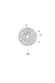
- FIG. 1 is a schematic diagram of a cross section of a positive electrode active material according to one embodiment.
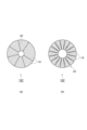
- (a) and (b) are schematic cross-sectional views of a raw material positive electrode active material used for manufacturing the positive electrode active material.
- (a) is a cross-sectional SEM photograph of the raw material positive electrode active material of Example 1
- (b) is a cross-sectional SEM photograph of the activated positive electrode active material obtained in Example 1.
- (a) is a cross-sectional SEM photograph of the raw material positive electrode active material of Example 2
- (b) is a cross-sectional SEM photograph of the activated positive electrode active material obtained in Example 2.
- (a) is a cross-sectional SEM photograph of the raw material positive electrode active material of Example 3, and (b) is a cross-sectional SEM photograph of the activated positive electrode active material obtained in Example 3.
- the positive electrode active material for a lithium ion secondary battery according to the present embodiment includes a plurality of secondary particles in which a plurality of primary particles aggregate, and satisfies the following requirements.
- the secondary particles have a plurality of voids inside, and the 50% frequency value of the area-based cumulative frequency distribution of the equivalent circle diameter of the voids based on the cross-sectional image of the secondary particles is less than 0.2 ⁇ m. It is approximately 0.65 ⁇ m or less, and the 50% frequency value of the area-based cumulative frequency distribution of the circularity of the void based on the cross-sectional image of the secondary particle group is 2.2 or more and 6.5 or less.
- the primary particles are oxides containing one or more elements selected from element group 1 below and one or more elements selected from element group 2 below.
- Element group 1 Ni, Co, Mn, Fe, Al, P
- Element group 2 Li, Na, K, Ca, Sr, Ba, Mg
- FIG. 1 shows a schematic cross-sectional view of an example of a positive electrode active material 100 according to the present embodiment.
- the positive electrode active material 100 is a secondary particle (agglomerate) in which a large number of primary particles 10 are aggregated. Grain boundaries 20 are formed between the primary particles 10.
- the positive electrode active material 100 has many voids 30.
- the voids 30 may be completely embedded within the primary particles 10 or may be present at the grain boundaries 20, that is, between the primary particles 10.
- a void is a void that is closed in cross section and does not communicate with the outside of the secondary particle. It is preferable that the voids 30 exist within the primary particles.
- the value ECD50 of the 50% frequency of the area-based cumulative frequency distribution of the equivalent circular diameter of the void 30 based on the cross-sectional image of the positive electrode active material (secondary particles) is greater than 0.2 ⁇ m and less than or equal to 0.65 ⁇ m. be.
- the value ECD50 may be greater than or equal to 0.25 ⁇ m, may be greater than or equal to 0.3 ⁇ m, and may be greater than or equal to 0.4 ⁇ m.
- the value ECD50 may be 0.6 ⁇ m or less, 0.55 ⁇ m or less, or 0.5 ⁇ m or less.
- the 50% frequency value CRT50 of the area-based cumulative frequency distribution of the circularity of the voids based on the cross-sectional image of the positive electrode active material (secondary particles) group is 2.2 or more and 6.5 or less.
- the value CRT50 may be greater than or equal to 2.5.
- the value CRT50 may be 6.0 or less, 5.5 or less, or 5.0 or less.
- the cross-sectional image can be an image obtained by a scanning electron microscope, and an image by a field emission scanning electron microscope is preferable.
- the accelerating voltage can be 5 kV
- the magnification can be about ⁇ 1000
- the image resolution can be 0.023 ⁇ m/pix.
- samples for which cross-sectional images are taken are samples in which a group of positive electrode active materials (secondary particles) are embedded in resin, samples in which a positive electrode active material layer is embedded in resin, or samples in which a positive electrode is embedded in resin. be.
- Various cross-section processing methods such as ion milling and polishing methods can be applied to cross-section the sample.
- the equivalent circular diameter of the secondary particles whose voids are to be detected is 1.5 ⁇ m or more. Further, it is preferable to use voids having an equivalent circle diameter of 0.05 ⁇ m or more as targets for detection of area, etc.
- the circularity of the void is defined as L 2 /4 ⁇ S, where L is the perimeter of the void, and S is the area of the void.
- the circularity takes a value of 1 or more, and the closer it is to 1, the closer it is to a circle.
- Each void in the cross-sectional image can be detected using image analysis software, etc., and the area, equivalent circle diameter, and circularity can be determined. Furthermore, by weighting each of the equivalent circle diameter and circularity based on the area of the voids instead of based on the number of voids, it is possible to obtain an area-based cumulative frequency distribution.
- the total number of secondary particles in the cumulative frequency distribution can be about 500, and the total number of voids in the cumulative frequency distribution is preferably from several thousand to several tens of thousands.
- the average porosity of the secondary particles in the cross-sectional image can be 3 to 15%.
- the average porosity may be 4% or more, or 5% or more.
- the average porosity of the secondary particles may be 14% or less, or 13% or less.
- the porosity of each secondary particle in the cross-sectional image is the area ratio of the total voids of each secondary particle to the total cross-sectional area (including voids) of each secondary particle.
- the objects to be measured are secondary particles having an equivalent circular diameter of 1.5 ⁇ m or more, and the average porosity can be obtained by the arithmetic average of the porosity of 500 secondary particles.
- the value D50 of the 50% frequency of the cumulative volume particle size distribution of secondary particles (positive electrode active material) determined by laser diffraction method may be 0.1 ⁇ m or more, 1 ⁇ m or more, 2 ⁇ m or more, and 500 ⁇ m or less. It may be 200 ⁇ m or less, 100 ⁇ m or less, 50 ⁇ m or less, or 20 ⁇ m or less.
- the positive electrode active material is represented by Li 1+a M 2 b M 1 M T c O 2+d X e (Formula A).
- M2 represents at least one element selected from the group consisting of Na, K, Ca, Sr, Ba, and Mg
- M1 represents the group consisting of Ni, Co, Mn, Fe, Al
- P represents the group consisting of transition metal elements other than Ni, Co, Mn, and Fe
- X represents a non-element other than O and P.
- MT is Cu, Ti, Mg, Al, W, Mo, Nb, Zn, Sn, Zr, Ga, V, B, Si, Ca, Sr, Ba, Ge, Cr, Sc, Y, La, Ta, Preferably, it is at least one element selected from the group consisting of Tc, Ru, Rh, Pd, Ag, Cd, and In.
- Examples of X are F, S, Cl, Br, I, Se, Te, and N.
- M1 it is preferable that at least Ni is included.
- the mole fraction of Ni in M 1 is more preferably 0.3 to 0.95.
- the crystal structure of the composite oxide is not particularly limited, but a layered structure is preferred, and a hexagonal or monoclinic crystal structure is more preferred.
- the hexagonal crystal structure is P3, P3 1 , P3 2 , R3, P-3, R-3, P312, P321, P3 1 12, P3 1 21, P3 2 12, P3 2 21, R32, P3m1, P31m, P3c1, P31c, R3m, R3c, P-31m, P-31c, P-3m1, P-3c1, R-3m, R-3c, P6, P6 1 , P6 5 , P6 2 , P6 4 , P6 3 , P-6, P6/m, P6 3 /m, P622, P6 1 22, P6 5 22, P6 2 22, P6 4 22, P6 3 22, P6 mm, P6 cc, P6 3 cm, P6 3 mc, P- It belongs to any one space group selected from the group consisting of 6m2, P-6c2, P-62m, P-62c, P6/mmm, P6/mcc, P6 3 /mcm, and P6 3 /mmc.
- the crystal structure of the monoclinic type is from P2, P2 1 , C2, Pm, Pc, Cm, Cc, P2/m, P2 1 /m, C2/m, P2/c, P2 1 /c and C2/c. belongs to any one space group selected from the group .
- the crystal structure of the positive electrode active material is identified from a powder X-ray diffraction pattern obtained by powder X-ray diffraction measurement using CuK ⁇ radiation as a radiation source.
- the positive electrode active material according to the present embodiment has high circularity and includes voids with a relatively small equivalent circle diameter, and has low SOC dependence of battery resistance in a lithium ion secondary battery. Although the reason for this is not clear, the following contributions may be considered.
- a lithium ion secondary battery charging and discharging are performed with intercalation and desorption of lithium ions at the interface between the positive electrode active material and the electrolyte, and the lithium ions diffuse through the crystals within the positive electrode material particles.
- the occupancy rate of lithium ion seats is high, so the diffusion of lithium ions into particles tends to be small, which tends to increase battery resistance.
- the interface between the positive electrode active material and the electrolyte increases, which activates the intercalation and desorption of lithium ions at the interface, but the gap between the primary particles increases the secondary Diffusion of lithium ions throughout the secondary particles is inhibited.
- the positive electrode active material according to the embodiment of the present invention can be manufactured, for example, by the following steps (1) to (3).
- Step (1) A step of mixing an activation treatment agent containing one or more alkali metal compounds into an electrode composite material containing a positive electrode active material and a binder.
- Step (2) The obtained A step of heating the mixture to a holding temperature equal to or higher than the melting start temperature of the activation treatment agent to activate the positive electrode active material contained in the mixture.
- Step (1) Activation treatment agent mixing step In step (1), the electrode composite material and the alkali metal compound are mixed to obtain a mixture.
- an electrode composite material containing a positive electrode active material and a binder is prepared.
- the electrode composite material may include a positive electrode active material, a binding material, and an electrolyte, and may be an electrode composite material in which at least a portion of the electrolyte is removed by contact with an electrolyte cleaning solvent.
- the electrode composite material before contact includes a positive electrode active material and a binding material, and the positive electrode active materials are bound to each other by the binding material.
- the electrode composite material may further include a conductive material, in which case the positive electrode active material and the conductive material are bound to each other by a binder.
- the electrode mixture may further contain an electrolyte.
- the electrolyte is a component derived from the electrolyte of the battery and impregnated into the electrode mixture.
- ⁇ Cathode active material> examples of positive electrode active materials are lithium, oxygen, fluorine, sodium, magnesium, aluminum, silicon, phosphorus, sulfur, potassium, calcium, titanium, vanadium, chromium, manganese, iron, cobalt, nickel, copper, zinc, gallium, and yttrium. It is a composite compound whose constituent elements are niobium, molybdenum, silver, indium, tungsten, etc.
- the positive electrode active material may be composed of only a single compound, or may be composed of a plurality of compounds.
- An example of a suitable positive electrode active material is a composite oxide containing one or more elements selected from element group 1 below and one or more elements selected from element group 2 below.
- Element group 1 Ni, Co, Mn, Fe, Al
- P Element group 2 Li, Na, K, Ca, Sr, Ba, Mg
- the positive electrode active material is preferably represented by the following chemical formula.
- M2 represents at least one element selected from the group consisting of Na, K, Ca, Sr, Ba, and Mg
- M1 represents at least one element selected from the group consisting of Ni, Co, Mn, Fe, Al, and P
- M T represents at least one element selected from the group consisting of Ni, Co, Mn, and transition metal elements other than Fe
- X represents at least one element selected from the group consisting of nonmetallic elements excluding O and P, Satisfies -0.4 ⁇ a ⁇ 1.5, 0 ⁇ b ⁇ 0.5, 0 ⁇ c ⁇ 0.5, -0.5 ⁇ d ⁇ 1.5, 0 ⁇ e ⁇ 0.5.
- MT is Cu, Ti, Mg, Al, W, Mo, Nb, Zn, Sn, Zr, Ga, V, B, Si, Ca, Sr, Ba, Ge, Cr, Sc, Y, La, Ta, Preferably, it is at least one element selected from the group consisting of Tc, Ru, Rh, Pd, Ag, Cd, and In.
- X are F, S, Cl, Br, I, Se, Te, N.
- the positive electrode active material is preferably a composite oxide containing at least Li and Ni.
- the mole fraction of Ni in M 1 is more preferably from 0.3 to 0.95.
- the crystal structure of the composite oxide as the positive electrode active material is not particularly limited, but a preferred crystal structure is a layered structure. More preferably, it has a hexagonal or monoclinic crystal structure.
- the hexagonal crystal structure is P3, P3 1 , P3 2 , R3, P-3, R-3, P312, P321, P3 1 12, P3 1 21, P3 2 12, P3 2 21, R32, P3m1, P31m, P3c1, P31c, R3m, R3c, P-31m, P-31c, P-3m1, P-3c1, R-3m, R-3c, P6, P6 1 , P6 5 , P6 2 , P6 4 , P6 3 , P-6, P6/m, P6 3 /m, P622, P6 1 22, P6 5 22, P6 2 22, P6 4 22, P6 3 22, P6 mm, P6 cc, P6 3 cm, P6 3 mc, P- It belongs to any one space group selected from the group consisting of 6m2, P-6c2, P-62m, P-62c, P6/mmm, P6/mcc, P6 3 /mcm, and P6 3 /mmc.
- the crystal structure of the monoclinic type is from P2, P2 1 , C2, Pm, Pc, Cm, Cc, P2/m, P2 1 /m, C2/m, P2/c, P2 1 /c and C2/c. belongs to any one space group selected from the group .
- the positive electrode active material may be in the form of secondary particles, which are aggregates of a plurality of primary particles.
- the conductive material examples include a metal-based conductive material such as metal particles, and a carbon-based conductive material made of a carbon material.
- carbon-based conductive materials are specifically graphite powder, carbon black (eg, acetylene black), and fibrous carbon materials (eg, graphitized carbon fibers, carbon nanotubes).
- the carbon-based conductive material may be a single carbon material or may be composed of multiple carbon materials.
- the specific surface area of the carbon material used as the carbon-based conductive material can generally be 0.1 to 500 m 2 /g.
- the conductive material may consist only of a carbon-based conductive material with an area of 30 m 2 /g or more, may be carbon black with an area of 30 m 2 /g or more, or may be acetylene black with an area of 30 m 2 /g or more.
- the speed of oxidation treatment of the carbon-based conductive material can be increased, and even carbon materials with a small specific surface area can be oxidized. may be possible.
- binding material (binding material before activation treatment) included in the electrode composite material
- thermoplastic resins and specifically, polyvinylidene fluoride (hereinafter sometimes referred to as PVdF), polytetrafluorocarbon Ethylene (hereinafter sometimes referred to as PTFE), tetrafluoroethylene/propylene hexafluoride/vinylidene fluoride copolymer, propylene hexafluoride/vinylidene fluoride copolymer, and tetrafluoroethylene/perfluoride
- fluororesins such as vinyl ether copolymers
- polyolefin resins such as polyethylene and polypropylene
- SBR styrene-butadiene copolymers
- the amounts of the positive electrode active material, conductive material, and binder in the electrode mixture there are no particular limitations on the amounts of the positive electrode active material, conductive material, and binder in the electrode mixture.
- the blending amount of the binder may be 0.5 to 30 parts by weight, and may be 1 to 5 parts by weight, based on 100 parts by weight of the positive electrode active material.
- the amount of the conductive agent may be 0, but may be 0 to 50 parts by weight, and may be 1 to 10 parts by weight, based on 100 parts by weight of the positive electrode active material.
- electrolytes are LiPF6 , LiBF4 , LiClO4 , LiN( SO2CF3 ) 2 , LiN( SO2F ) 2 , LiCF3SO3 .
- electrolytes There is no limit to the amount of electrolyte contained in the electrode mixture, but it can be from 0.0005 to 7% by mass.
- the electrode mixture may contain a solvent derived from the electrolyte.
- solvents are dimethyl carbonate, diethyl carbonate, ethylmethyl carbonate.
- Such an electrode mixture can be obtained by separating and recovering the electrode mixture from a waste electrode having a current collector and an electrode mixture layer.
- “Waste electrodes” can be electrodes recovered from discarded batteries and electrode waste generated during the manufacturing process of electrodes and batteries.
- the discarded battery may be a used battery or an unused but substandard battery.
- the electrode waste may be electrode ends generated during the battery manufacturing process and non-standard electrodes. Further, it is also possible to use a waste product of the electrode composite material that is not attached to the current collector and is generated in the electrode composite material manufacturing process.
- cracks are formed between the primary particles 10 in the secondary particles 100' of the positive electrode active material, as shown in FIG. 2(b).
- cracks 25 are formed between the primary particles 10 in the secondary particles 100' as shown in (a) of FIG. Often not formed.
- cracks may or may not occur in the positive electrode active material serving as a raw material.
- the electrode has a current collector that is a metal foil such as aluminum foil or copper foil, and an electrode mixture layer provided on the current collector.
- the electrode mixture layer may be provided on one side or both sides of the current collector.
- a method for separating an electrode having an electrode mixture layer and a current collector from the electrode mixture is to mechanically peel off the electrode mixture layer from the current collector (for example, by scraping the electrode mixture from the current collector).
- Method of peeling the electrode composite material layer from the current collector by infiltrating the interface between the electrode composite material layer and the current collector A method of dissolving the current collector using an alkaline or acidic aqueous solution.
- the method involves mechanically peeling off the electrode mixture layer from the current collector.
- the prepared electrode mixture is brought into contact with an electrolyte cleaning solvent to remove at least a portion of the electrolyte from the electrode mixture.
- an electrode mixture containing a positive electrode active material, a binder, and an electrolyte is brought into contact with an electrolyte cleaning solvent to obtain a slurry containing a solid component and a liquid component, and then the slurry is mixed with a solid component. and a liquid component.
- Solid-liquid separation is a process of separating the slurry into a liquid component and a solid component.
- the solid-liquid separation method may be any conventionally known method, such as filtration or centrifugation.
- electrolyte cleaning solvent there are no particular limitations on the electrolyte cleaning solvent.
- carbonate esters such as ethylene carbonate, dimethyl carbonate, ethyl methyl carbonate, diethyl carbonate, and propylene carbonate
- water ketones such as acetone, methyl ethyl ketone, diethyl ketone, and methyl isobutyl ketone
- examples include alcohols.
- the electrolyte cleaning solvent can be brought into contact with the electrode mixture using a known powder-liquid contact device, such as a stirring tank.
- the slurry concentration that is, the concentration of the solid component relative to the volume of the slurry, is 3 to 2000 g/L.
- the step of bringing the electrode mixture into contact with the electrolyte cleaning solvent it is preferable to stir the electrode mixture and the cleaning solvent to obtain a slurry.
- the peripheral speed of the tip of the stirring blade can be 0.1 to 1.0 m/s.
- Step (4) is a step of obtaining an electrode composite from which at least a portion of the electrolyte in step (1) has been removed, and includes a positive electrode active material, a binder, and a step of bringing the electrode mixture containing the electrolyte into contact with an electrolyte cleaning solvent to obtain a slurry containing a solid component and a liquid component, and then separating the slurry into the solid component and the liquid component.
- the amount of P in the liquid component after separation is 0.0020 to 2.0% by mass
- the amount of F is 0.01 to 7.0% by mass
- the amount of P remaining in the solid component after separation is 0.
- the content is preferably .7% by mass or less.
- the obtained solid component may be rinsed.
- Rinsing is an operation in which the obtained solid component is brought into contact with an electrolyte cleaning solvent again to obtain a slurry, and then the slurry is again separated into a solid component and a liquid component.
- rinsing may be performed multiple times.
- the slurry concentration in rinsing can also be the same as above.
- the slurry can be stirred as described above.
- the contact time between the solid component and the liquid component is 1 minute or more and less than 25 hours.
- the contact time between the solid component and the liquid component in the step of cleaning the electrode composite material is the time during which the electrode composite material and the electrolyte cleaning solvent are in contact with each other.
- the contact time between the solid component and the liquid component is such that the electrode mixture (solid component) containing the electrolyte starts contacting with the electrolyte cleaning solvent, and then the slurry is mixed with the solid component and the liquid component. This is the time A required to complete the operation of solid-liquid separation into liquid components.
- the contact time between the solid component and the liquid component is the above-mentioned time A, and in each rinsing process, the contact time between the solid component after separation and the electrolyte cleaning solvent is started, and then the solid component is This is the sum of the time B required to complete solid-liquid separation between the components and the liquid component.
- the completion time of solid-liquid separation is the end time of filtration.
- the amount of P in the liquid component after solid-liquid separation is 0.0020 to 2.0% by mass
- the amount of F is 0.01 to 7.0% by mass
- the amount of P remaining in the subsequent solid component may be 0.7% by mass or less.
- the electrolyte can be sufficiently removed from the electrode mixture. For example, if the electrolyte remains, the following reaction occurs, and the structure of the positive electrode active material changes from a layered rock salt structure to a spinel structure.
- lithium carbonate is included as an activator, lithium is also consumed by the following reaction.
- all the liquid components obtained in the first solid-liquid separation and the liquid components obtained in the subsequent one or more rinsing solid-liquid separations are The contents of P and F in the total mixed liquid components satisfy 0.0020 to 2.0% by mass and 0.01 to 7.0% by mass, respectively.
- the P content in the solid component obtained in the final solid-liquid separation satisfies 0.7% by mass or less.
- the contents of P and F in the liquid components continuously discharged from the apparatus may fall within the above range.
- the P content in the liquid component obtained in the final solid-liquid separation is 2. It is preferable that the content of F is 0% by mass or less, and the content of F is 7.0% by mass or less, the content of P is 0.0020% by mass or more, and the content of F is 0.01% by mass or more. It is also preferable that there be.
- the amount of P and the amount of F relative to the liquid components discharged from the device are in the range of 0.0020 to 2.0 mass% and 0.01 to 7.0 mass%, respectively. All you have to do is enter.
- the amount of P remaining in the solid component after solid-liquid separation may be 0.0001% by mass or more.
- the amount of F remaining in the solid component after solid-liquid separation can be 3.5% by mass or less, and may be 0.0001% by mass or more.
- the electrolyte cleaning solvent of the separated solid component can be dried by reducing pressure and/or heating, if necessary.
- the heating temperature can be 50 to 200°C.
- an activation treatment agent containing at least one compound selected from the group consisting of potassium compounds and sodium compounds is mixed into the prepared electrode mixture after the electrolyte has been removed to obtain a mixture.
- the mixing method of the electrode mixture and the activation treatment agent may be either dry mixing or wet mixing, or a combination of these mixing methods, and the mixing order is not particularly limited.
- a mixing device equipped with mixing media such as balls to perform a pulverizing and mixing step, which can improve mixing efficiency.
- dry mixing is preferable because mixing can be performed more easily.
- a V-type mixer, a W-type mixer, a ribbon mixer, a drum mixer, a powder mixer equipped with an internal stirring blade, a ball mill, a vibration mill, or a combination of these devices can be used.
- a powder mixer equipped with an internal stirring blade is preferable, and a specific example is a Loedige mixer (manufactured by Matsubo Co., Ltd.).
- the activation treatment agent contains at least one compound selected from the group consisting of potassium compounds and sodium compounds.
- potassium and/or sodium may be referred to as alkali metal element X.
- the activation treatment agent may contain an alkali metal compound containing another alkali metal such as Li.
- the positive electrode active material When the activation treatment agent comes into contact with the positive electrode active material, the positive electrode active material can be activated.
- the alkali metal compound in the activation treatment agent includes a molten portion, the contact between the molten portion and the positive electrode active material is improved, thereby further promoting activation of the positive electrode active material.
- the electrode mixture may contain a fluorine-containing compound derived from the binder and/or electrolyte, but by bringing the fluorine-containing compound into contact with the activation treatment agent, the fluorine component can be removed. Since it is stabilized as an alkali metal fluoride, generation of corrosive gases such as hydrogen fluoride can be suppressed. Note that it is desirable to prevent the generation of hydrogen fluoride because it reduces the activity of the positive electrode active material.
- the proportion of the total alkali metal compound in the activation treatment agent is set appropriately taking into account the type of alkali metal compound and the type of target positive electrode active material. , 50% by weight or more, preferably 70% by weight or more (including 100% by weight).
- the concentration of at least one alkali metal selected from the group consisting of potassium and sodium among the alkali metals contained in the alkali metal compound can be arbitrarily adjusted from 0 to 100 mol%, but preferably 10 mol% or more, More preferably, it is 20 mol% or more, preferably 90 mol% or less, and even more preferably 80 mol% or less.
- Alkali metal compounds that are components of the activation treatment agent include hydroxides, borates, carbonates, oxides, peroxides, superoxides, nitrates, phosphates, sulfates, and chlorides of alkali metals. vanadate, bromate, molybdate, and tungstate. These can be used alone or in combination as a component of the activation treatment agent.
- alkali metal compounds include hydroxides such as LiOH, NaOH, KOH, RbOH, and CsOH; Boric oxides such as LiBO2 , NaBO2 , KBO2 , RbBO2 , CsBO2 ; Carbonates such as Li2CO3 , Na2CO3 , K2CO3 , RbCO3 , CsCO3 ; Oxides such as Li 2 O, Na 2 O, K 2 O, Rb 2 O, Cs 2 O; Peroxides such as Li2O2 , Na2O2 , K2O2 , Rb2O2 , Cs2O2 ; Superoxides such as LiO2 , NaO2 , KO2 , RbO2 , CsO2 ; Nitrates such as LiNO3 , NaNO3 , KNO3 , RbNO3 , CsNO3 ; Phosphates such as Li 3 PO 4 , Na 3 PO 4 , K 3 PO 4 , R
- the activation treatment agent is added to the positive electrode active material in the electrode mixture in addition to at least one compound selected from the group consisting of potassium compounds and sodium compounds.
- the same alkali metal element as the alkali metal element contained can be contained.
- the activation treatment agent contains a lithium compound in addition to at least one compound selected from the group consisting of potassium compounds and sodium compounds.
- Suitable lithium compounds include LiOH, LiBO2 , Li2CO3 , Li2O , Li2O2 , LiO2 , LiNO3 , Li3PO4 , Li2SO4 , LiCl , LiVO3 , LiBr, Li Examples include 2MoO4 and Li2WO4 .
- the activation treatment agent may contain compounds other than the alkali metal compound as necessary.
- compounds other than alkali metal compounds include alkaline earth metal compounds containing alkaline earth metal elements such as magnesium, calcium, and barium.
- the alkaline earth metal compound is contained in the activation treatment agent together with the alkali metal compound for the purpose of controlling the melting start temperature of the activation treatment agent.
- the content of compounds other than the alkali metal compound in the activation treatment agent is selected within a range that does not significantly inhibit the effects derived from the above-mentioned molten alkali metal compound, and is less than 50% by weight of the total weight of the activation treatment agent. can be.
- the amount of the activation treatment agent added in the mixture of the electrode mixture and the activation treatment agent is preferably 0.001 to 100 times the weight of the positive electrode active material contained in the electrode mixture, and more preferably, It is 0.05 to 1 times.
- the number of moles of the alkali metal compound in the activation treatment agent in the mixture of the electrode mixture and the activation treatment agent is 1 when the number of moles of the positive electrode active material (for example, formula A) contained in the electrode mixture is 1. It can be added so that the number of moles of the element becomes 0.001 to 200 times as much.
- the ratio of the activation treatment agent in the mixture By appropriately controlling the ratio of the activation treatment agent in the mixture, it is possible to reduce the cost of recovering the positive electrode active material from the electrode mixture and increase the oxidative decomposition processing speed of the carbon-based conductive material and binder. Can be done. Further, the effect of preventing the generation of corrosive gas in the activation treatment step can be improved, and furthermore, the discharge capacity of a battery manufactured using the obtained positive electrode active material can be further increased.
- At least one kind of alkali metal compound contained in the activation treatment agent is an alkali metal compound that exhibits alkalinity when dissolved in water.
- an activation treatment agent containing such an alkali metal compound is dissolved in pure water, the pH of the solution becomes higher than 7.
- such an activation treatment agent may be referred to as an "alkaline activation treatment agent.”
- an alkaline activation treatment agent By using an alkaline activation treatment agent, it is possible to further suppress the generation of corrosive gas during the heating process, thereby further increasing the discharge capacity of batteries manufactured using the recovered positive electrode active material. can. Further, by using an alkaline activation treatment agent, the processing speed of the carbon-based conductive material and the binder can be increased.
- Alkali metal compounds that exhibit alkalinity when dissolved in water contained in alkaline activation treatment agents include alkali metal hydroxides, carbonates, hydrogen carbonates, oxides, peroxides, and superoxides. Can be mentioned. Specifically, LiOH, NaOH, KOH , RbOH, CsOH; Li2CO3 , Na2CO3 , K2CO3 , RbCO3 , CsCO3 ; LiHCO3 , NaHCO3 , KHCO3 , RbHCO3 , CsHCO3 ; Li2O , Na2O , K2O , Rb2O , Cs2O ; Li2O2, Na2O2 , K2O2 , Rb2O2 , Cs2O2 ; LiO2 , NaO 2 , KO2 , RbO2 , CsO2 ; One or more of these may be included in the activation treatment agent.
- the conductive material contained in the electrode composite material is a carbon-based conductive material
- at least one kind of alkali metal compound contained in the activation treatment agent is removed from the carbon-based conductive material at the temperature of the activation treatment step. It may also be an alkali metal compound having an oxidizing power to oxidize and decompose the conductive material. Note that an activation treatment agent containing such an alkali metal compound may be hereinafter referred to as an "activation treatment agent having oxidizing power.”
- an activation treatment agent having such oxidizing power When an activation treatment agent having such oxidizing power is used, it can promote the oxidation of the conductive material, which is a carbon material, to carbon dioxide, and the oxidation of the binding material, which is a hydrocarbon material, to carbon dioxide and water vapor. It is particularly effective in increasing the discharge capacity of batteries manufactured using the obtained positive electrode active material, and further improving the effect of preventing the generation of corrosive gas during the activation treatment process. There are cases.
- alkali metal compounds having the oxidizing power necessary to oxidize carbon-based conductive materials and hydrocarbons into carbon dioxide and water vapor include alkali metal peroxides, superoxides, nitrates, sulfates, vanadates, Mention may be made of molybdates. These may be used alone or in combination of two or more.
- Step (2) Heating step The heating step is to heat the mixture obtained in step (1) (hereinafter sometimes referred to as "mixture before heating") to a temperature higher than the melting start temperature of the activation treatment agent. This is the process of heating to .
- the mixture obtained in this heating step may be referred to as a “mixture after heating.”
- melting start temperature (Tmp) of the activation treatment agent means the lowest temperature at which a part of the activation treatment agent exhibits a liquid phase.
- the melting start temperature (Tmp) of the activation treatment agent is a value determined by differential thermal measurement (DTA). That is, 5 mg of the mixture before heating is subjected to differential thermal measurement (DTA, measurement conditions: heating rate: 10° C./min), and the temperature at which the DTA signal shows an endothermic peak is defined as the melting start temperature (Tmp).
- DTA differential thermal measurement
- the melting start temperature (Tmp) of the activation treatment agent is preferably 700°C or lower, more preferably 600°C or lower. Although there is no lower limit to the melting start temperature (Tmp) of the activation treatment agent, it may be, for example, 150°C.
- the melting point of the activation treatment agent means the lowest temperature at which a part of the activation treatment agent exhibits a liquid phase when only the activation treatment agent is heated.
- the melting start temperature (Tmp) of the activation treatment agent becomes lower than the melting point of the activation treatment agent.
- the melting point of the activation treatment agent is a value determined by differential thermal analysis (DTA). Specifically, 5 mg of the activation treatment agent was subjected to differential thermal measurement (DTA, measurement conditions: heating rate: 10°C/min), and the temperature at which the DTA signal shows the endothermic peak was determined as the melting point of the activation treatment agent. do.
- DTA differential thermal analysis
- the atmosphere for heating is not particularly limited, and may be an oxygen-containing gas such as air, nitrogen, argon, or carbon dioxide.
- the pressure of the atmosphere is not particularly limited, and may be atmospheric pressure, but may also be a reduced pressure atmosphere or a pressurized atmosphere.
- step (2) the following effects occur by heating the mixture before heating to a temperature equal to or higher than the melting start temperature (Tmp) of the activation treatment agent as described above.
- Tmp melting start temperature
- the rate of oxidative decomposition of the conductive material and the binder increases, and furthermore, the molten activation treatment agent contacts the binder and the binder.
- the fluorine component is stabilized as an alkali metal fluoride, preventing the generation of hydrogen fluoride, a corrosive gas, and suppressing deterioration of the crystal structure of the positive electrode active material.
- the activation treatment agent contains the same alkali metal as the positive electrode active material, it is also possible to supply the insufficient alkali metal to the positive electrode active material.
- the temperature of the heating process and the holding time at that temperature depend on the types of alkali metal compounds and other compounds contained in the positive electrode active material, conductive material, binding material, and activation treatment agent that make up the electrode mixture. It can be adjusted as appropriate depending on the combination. Usually, the temperature is in the range of 100 to 1500°C, and the holding time is about 10 minutes to 24 hours.
- the temperature of the heating step is preferably higher than the melting point of the alkali metal compound contained in the activation treatment agent. Note that the melting point of the alkali metal compound may be lower than the melting point of each compound alone by mixing multiple types of compounds.
- the eutectic point is the melting point of the alkali metal compounds.
- the mixture can be cooled to any temperature, such as room temperature, if necessary.
- Step (3) Solid-liquid separation step (alkali metal removal) This step is a step in which the heated mixture is brought into contact with a liquid containing water to obtain a slurry containing a solid component and a liquid component, and then the slurry is separated into a solid component and a liquid component.
- the total content of potassium and sodium in the liquid component after separation is 0.090 to 2.0% by mass or less, and the total content of potassium and sodium in the solid component after separation is 1.2% by mass or less. It is preferable that there be.
- the mixture after heating contains, in addition to the positive electrode active material, components derived from the activation treatment agent (alkali metal compounds, etc.), undecomposed conductive materials and binding materials, and other undecomposed electrode composite materials. . Furthermore, when the electrode mixture contains an electrolytic solution containing a fluorine component, it may contain a fluorine component derived from the electrolyte.
- a water-containing liquid is added to the mixture to form a slurry, followed by solid-liquid separation to separate into a solid component and a liquid component.
- the liquid used in the slurrying step is not particularly limited as long as it contains water.
- the amount of water in the liquid may be 50% by weight or more.
- components other than water may be added to the liquid to adjust the pH.
- liquids containing water include pure water and alkaline cleaning liquid.
- alkaline cleaning liquid for example, an aqueous solution of one or more anhydrides and hydrates thereof selected from the group consisting of lithium hydroxide, sodium hydroxide, potassium hydroxide, lithium carbonate, sodium carbonate, potassium carbonate, and ammonium carbonate. can be mentioned. Ammonia can also be used as the alkali.
- the resulting slurry contains a solid component mainly containing the positive electrode active material and a liquid component containing water-soluble components other than the positive electrode active material.
- the liquid component includes an alkali metal component derived from the activation treatment agent and/or a fluorine component derived from the binder and the electrolyte.
- the amount of liquid added to the mixture is appropriately determined in consideration of the respective amounts of the positive electrode active material and water-soluble components other than the positive electrode active material contained in the mixture.
- step (3) it is preferable to bring the heated mixture into contact with a liquid containing water such that the slurry concentration, that is, the concentration of solid components relative to the volume of the slurry, is 12 to 1000 g/L.
- step (3) it is preferable to stir the heated mixture and the water-containing liquid to obtain a slurry. This promotes dissolution of water-soluble components.
- the peripheral speed of the tip of the stirring blade is preferably 0.1 to 0.9 m/s.
- Solid-liquid separation is a process of separating the slurry into a liquid component and a solid component.
- the solid-liquid separation method may be any conventionally known method, such as filtration or centrifugation.
- step (3) after solid-liquid separation, the obtained solid component may be rinsed.
- Rinsing is an operation in which the obtained solid component is brought into contact with a water-containing liquid again to obtain a slurry, and then the slurry is again separated into a solid component and a liquid component.
- rinsing may be performed multiple times.
- the slurry concentration in rinsing can also be the same as above.
- the rinse magnification can be 1-80.
- the rinsing ratio is the ratio of the weight of the added water-containing liquid to the weight of the solid component. Also during rinsing, the slurry can be stirred as described above.
- the contact time between the solid component and the liquid component is preferably 4 minutes or more and less than 24 hours.
- the contact time between the solid component and the liquid component in step (3) is the time during which the positive electrode active material and the liquid containing water are in contact. For example, if rinsing is not performed, the contact time between the solid component and the liquid component is determined by starting the contact between the solid component, such as a heated mixture, and the liquid containing water, and then adding the slurry to the solid component and the liquid component. This is the time C required to complete the operation of separating solid and liquid components.
- the contact time between the solid component and the liquid component is the above-mentioned time C, and in each rinsing step, after the solid component after separation starts contact with the liquid containing water, This is the sum of the time D required to complete solid-liquid separation between the solid component and the liquid component.
- the completion time of solid-liquid separation is the end time of filtration.
- the total content of potassium and sodium in the liquid component obtained by solid-liquid separation is 0.090 to 2.0% by mass, and the potassium and sodium content in the solid component obtained by solid-liquid separation is It is suitable that the total content of is 1.2% by mass or less.
- all the liquid components obtained in the first solid-liquid separation and the liquid components obtained in the subsequent one or more rinsing solid-liquid separations are The total content of potassium and sodium in the total mixed liquid components satisfies 0.090 to 2.0% by mass.
- the total content of potassium and sodium in the solid component obtained in the final solid-liquid separation satisfies 1.2% by mass or less.
- the total content of potassium and sodium in the liquid component continuously discharged from the apparatus may be in the range of 0.090 to 2.0% by mass.
- the total content of potassium and sodium in the liquid component obtained in the final solid-liquid separation when cleaning the electrode composite material is preferably 0.090 to 2.0% by mass.
- the lower limit of the total content of potassium and sodium in the separated solid component may be 0.001% by mass.
- This embodiment may include the following step (5) and/or step (6).
- Step (5) Drying Step Step (5) is a step of exposing the solid component obtained in step (3) to a heating and/or reduced pressure environment to remove water from the solid component.
- the ratio of the saturated water vapor pressure at the temperature of the solid component to the environmental pressure where the solid component is present is 80% or more. It is preferred to vary the ambient pressure and/or the temperature of the solid components.
- the ratio of the saturated water vapor pressure at the temperature of the solid component to the ambient pressure where the solid component exists is 80% or more, water is sufficiently removed from the solid component.
- conditions may be reached where water is sufficiently removed from the solid component only by reduced pressure, conditions may be reached where water is sufficiently removed from the solid component only by heating, and conditions may be reached where water is sufficiently removed from the solid component only by heating. Conditions may be reached in which water is sufficiently removed from the solid component by .
- the time required for the ratio of the saturated water vapor pressure at the temperature of the solid component to the ambient pressure where the solid component exists to reach 80% or more is measured by monitoring the environmental pressure where the solid component exists and the temperature of the solid component.
- sensors such as a pressure gauge and a hygrometer provided in the dryer may be used.
- the heating temperature is preferably 100°C or higher in order to remove water. Furthermore, in order to sufficiently remove moisture, the temperature is preferably 150°C or higher. In particular, a temperature of 250° C. or higher is preferable because the discharge capacity of a battery manufactured using the obtained positive electrode active material further increases.
- the temperature in the drying step may be constant or may be changed stepwise or continuously.
- the temperature range reached by heating can be, for example, 10°C or more and less than 900°C.
- the ultimate pressure range of the reduced pressure can be, for example, 1.0 ⁇ 10 ⁇ 10 to 1.0 ⁇ 10 3 Pa.
- Process (6) Re-firing process (annealing)
- the solid component after step (5) is heat treated at less than 900°C.
- the atmosphere for heat treatment is preferably in an oxygen-containing atmosphere such as air.
- the temperature of the heat treatment can be 100° C. or higher.
- the holding time of the heat treatment can be from 1 minute to 24 hours. In particular, it is preferable to heat at a holding temperature of 350° C. or higher for 0.1 hour or more and 5 hours or less.
- the above positive electrode active material can be obtained.
- the discharge capacity of the finally obtained positive electrode active material according to the embodiment of the present invention can be 150 mAh/g or more.
- the binder and conductive material were mixed in a weight ratio of 92:3:5.
- the binder PVdF a binder solution in which PVdF was dissolved in NMP in advance was used.
- NMP was added and adjusted so that the total weight of the positive electrode active material, conductive material, and binder was 50% by weight.Kneaded with a rotation/revolution mixer (ARE-310, manufactured by Shinky Co., Ltd.), A positive electrode composite paste was manufactured.
- an NMP solution in which PVdF as a binder is dissolved is used, and NMP is added so that the total weight of the positive electrode active material, conductive material, and binder in the positive electrode composite paste is 50% by weight. Adjusted by adding.
- the positive electrode mixture paste was applied to aluminum foil 1085 for lithium ion secondary battery positive electrode current collector (manufactured by Nippon Seifu Co., Ltd.) with a thickness of 20 ⁇ m as a current collector, and the amount of positive electrode active material was 10.0 ⁇ 0.5 mg/cm. 2 and vacuum-dried at 150° C. for 8 hours to obtain a positive electrode.
- the electrode area of this positive electrode was 1.65 cm 2 .
- a non-aqueous electrolyte secondary battery (coin-type battery R2032) was manufactured by combining the above-described positive electrode, electrolyte, separator, and negative electrode. Note that the battery was assembled in a glove box with an argon atmosphere.
- electrolytic solution a solution was used in which LiPF 6 was dissolved at a ratio of 1.0 mol/L in a 30:35:35 (volume ratio) mixed solution of ethylene carbonate, dimethyl carbonate, and ethyl methyl carbonate.
- a laminated film separator in which a heat-resistant porous layer was laminated on a polyethylene porous film was used as a separator.
- metallic lithium was used as the negative electrode.
- Charge/Discharge Test Using the manufactured coin-type battery, a charge/discharge test was conducted under the conditions shown below while maintaining the battery at 25°C. The charge capacity and discharge capacity in the charge/discharge test were determined as follows.
- ⁇ Battery resistance measurement (AC method)> The battery resistance was measured at 25° C. at SOC of 10% and 80%, assuming that the discharge capacity measured in the above charge/discharge test was 100% of the depth of charge (hereinafter sometimes referred to as SOC). Note that adjustment to each SOC was performed in a 25°C environment. To measure battery resistance, leave the SOC-adjusted coin-shaped cell in a 25°C thermostatic chamber for 2 hours, and use an electrochemical measurement device (VSP-3e electrochemical measurement system manufactured by Biologic) to measure the battery resistance using the AC impedance method. Measurements were made. Amplitude voltage: 10mV Frequency range: 1MHz to 0.1Hz
- the battery resistance at 0.1 Hz in AC is equivalent to the battery resistance after 10 seconds in DC.
- the battery resistance at 10% SOC was defined as R (SOC 10%)
- the battery resistance at 80% SOC was defined as R (SOC 80%)
- the ratio of R (SOC 10%) and R (SOC 80%) was defined as the SOC dependence of the battery resistance.
- SOC dependence of battery resistance R (SOC 10%) / R (SOC 80%)
- the SOC dependence of the battery resistance described above is an index regarding the degree of increase in battery resistance at the end of discharge.
- a small dependence of battery resistance on SOC indicates that a change in battery resistance with respect to a change in SOC accompanying charging and discharging of the battery is small, which is preferable from the viewpoint of battery control.
- Battery resistance can also be measured using a direct current method.
- the battery resistance was measured at 25° C. at SOC of 10% and 80%, assuming that the discharge capacity measured in the above charge/discharge test was 100% of the depth of charge (hereinafter sometimes referred to as SOC). Note that adjustment to each SOC was performed in a 25°C environment.
- To measure battery resistance leave the SOC-adjusted coin-shaped cell in a 25°C thermostat for 2 hours, discharge at 2 mA for 15 seconds, leave it for 5 minutes, charge at 2 mA for 15 seconds, leave it for 5 minutes, and then put it at 4 mA for 15 seconds.
- Discharge leave for 5 minutes, charge for 30 seconds at 2mA, leave for 5 minutes, discharge for 15 seconds at 8mA, leave for 5 minutes, charge for 60 seconds at 2mA, leave for 5 minutes, discharge for 15 seconds at 16mA, leave for 5 minutes. , charging at 2 mA for 120 seconds, and standing still for 5 minutes.
- the battery resistance was determined by calculating the slope using the least squares approximation method from a plot of the battery voltage measured after 10 seconds when discharging 2, 4, 8, and 16 mA and each current value, and using this slope as the battery resistance. .
- the battery resistance after 10 seconds in DC corresponds to the battery resistance at 0.1 Hz in AC.
- the battery resistance at 10% SOC was defined as R (SOC 10%)
- the battery resistance at 80% SOC was defined as R (SOC 80%)
- the ratio of R (SOC 10%) and R (SOC 80%) was defined as the SOC dependence of the internal resistance.
- SOC dependence of battery resistance R (SOC 10%) / R (SOC 80%)
- the resistances measured by the AC method and the DC method described above both correspond to the battery resistance after 10 seconds of current application, so they can be compared with each other.
- the SOC dependence of internal resistance which is the ratio of R (SOC 10%) to R (SOC 80%)
- values measured by the AC method and the DC method can be compared with each other.
- the measurement was carried out using the direct current method in the examples, and the alternating current method in the comparative examples.
- the obtained positive electrode active material was embedded in resin to form a cross section.
- a cross-section processing device manufactured by JEOL, IB-19520CCP was used to form the cross-section.
- An image of the cross section of the positive electrode active material was taken using a scanning electron microscope (FE-SEM: manufactured by JEOL, JSM-7900F). The photographing conditions were as follows: acceleration voltage: 5 kV, magnification: ⁇ 1000, and image resolution: 0.023 ⁇ m/pix.
- a cross-sectional image of the secondary particles contained in the positive electrode active material is imported into a computer, and image analysis software is used to perform binarization processing using the intermediate value between the maximum and minimum brightness in the cross-sectional image of the secondary particles.
- a binarized image was obtained in which the internal cross section of the particle was given an arbitrary color, and the cross section of the voids existing inside the cross section of the secondary particle was converted into an arbitrary color.
- image analysis software for example, quantitative analysis software (TRI/3D-BON-FCS, manufactured by Ratoc System Engineering Co., Ltd.) was used.
- Secondary particles having an equivalent circular diameter of 1.5 ⁇ m or more were used as the secondary particles whose internal voids were to be detected, and the number of secondary particles was about 500.
- the detection targets were voids with an equivalent circle diameter of 0.05 ⁇ m or more, and the total number of voids detected within the secondary particles was several thousand to tens of thousands.
- the area ratio of the total voids of each secondary particle to the total cross-sectional area (including voids) of each secondary particle was determined, and the average porosity was determined from the arithmetic average of 500. .
- Example 1 A. Obtaining positive electrode A A new lithium ion secondary battery was disassembled and the positive electrode was taken out. The positive electrode had a structure in which positive electrode active material layers were laminated on both sides of a current collector. This lithium ion secondary battery had been charged and discharged several times. A SEM image of a cross section of the positive electrode active material of the active material layer of positive electrode A is shown in FIG. 3(a). Almost no cracks were observed in the secondary particles of the positive electrode active material along the grain boundaries of the primary particles.
- Electrolyte-containing electrode mixture cleaning process (corresponding to process (4)) The obtained electrolyte-containing electrode mixture was soaked in a sufficiently large amount of water. The obtained solid component was dried under reduced pressure at 100° C. for 1 hour, and the washed electrode mixture was collected.
- Activation treatment agent mixing process (corresponding to process (1)) After cleaning, Li 2 CO 3 and K 2 SO 4 were mixed into the electrode mixture as activation treatment agents so that the amounts were 0.15 mol and 0.15 mol per 1 mol of the positive electrode active material in the electrode mixture. A mixture (mixture before heating) was obtained. The melting start temperature of the activation treatment agent was 550°C.
- Heating process (corresponding to process (2)) The obtained pre-heated mixture was placed in an alumina firing container and placed in an electric furnace. The mixture was activated under atmospheric pressure at a holding temperature of 700° C. and a holding time of 6 hours. The heating rate was 300° C./hour, and cooling to room temperature was performed naturally. After cooling to room temperature, the post-activation mixture was collected.
- FIG. 3(b) A SEM photograph of the recovered activated positive electrode active material is shown in FIG. 3(b). The cracks between the primary particles disappeared, and many voids were formed within and between the primary particles.
- the composition of the activated positive electrode material was Li 1.15 Ni 1/3 Co 1/3 Mn 1/3 O 2 and the crystal structure was R-3m.
- the 50% cumulative volume particle size D50 of the positive electrode active material was 11 ⁇ m.
- a coin-type battery was manufactured using the recovered activated positive electrode active material, and after carrying out a predetermined constant current charge/discharge, the internal resistance was measured at a predetermined SOC, and the SOC dependence of the battery resistance was calculated.
- step A the used lithium ion secondary battery was disassembled and the positive electrode was taken out.
- the positive electrode had a structure in which positive electrode active material layers were laminated on both sides of a current collector. This lithium ion secondary battery was a deteriorated battery on the market and had been charged and discharged many times based on general use.
- a SEM image of a cross section of the positive electrode active material of the positive electrode active material layer is shown in FIG. 4(a). Numerous cracks were observed in the secondary particles of the positive electrode active material along the grain boundaries of the primary particles. Steps A to H were performed in the same manner as in Example 1, except that the origin of the positive electrode was different.
- the composition of the reactivated positive electrode material was Li 1.14 Ni 1/3 Co 1/3 Mn 1/3 O 2 and the crystal structure was R-3m.
- the 50% cumulative volume particle size D50 of the positive electrode active material was 10 ⁇ m.
- step A a used lithium ion secondary battery of a different type from Example 2 was disassembled and the positive electrode was taken out.
- the positive electrode had a structure in which positive electrode active material layers were laminated on both sides of a current collector.
- This lithium ion secondary battery was a forced cycle degraded battery and had been charged and discharged more times than in Example 2.
- a SEM photograph of a cross section of the positive electrode active material of the positive electrode active material layer is shown in FIG. 5(a). Numerous cracks were observed in the secondary particles of the positive electrode active material along the grain boundaries of the primary particles.
- Steps A to H were carried out in the same manner as in Example 1, except that the positive electrode was taken out from a different lithium ion secondary battery.
- the composition of the reactivated positive electrode material was Li 1.13 Ni 1/3 Co 1/3 Mn 1/3 O 2 and the crystal structure was R-3m.
- the 50% cumulative volume particle size D50 of the positive electrode active material was 9 ⁇ m.
- Example 1 The procedure was the same as in Example 1 except that commercially available particles of positive electrode active material (unused) were used as the final positive electrode active material without performing Steps D to H.
- the composition of the positive electrode active material was Li 1.04 Ni 1/3 Co 1/3 Mn 1/3 O 2 and the crystal structure was R-3m.
- a nickel sulfate aqueous solution, a cobalt sulfate aqueous solution, and a manganese sulfate aqueous solution are mixed so that the atomic ratio of nickel atoms, cobalt atoms, and manganese atoms is 0.55:0.21:0.24 to obtain a mixed raw material liquid. It was adjusted.
- this mixed raw material solution and an ammonium sulfate aqueous solution were continuously added as a complexing agent into the reaction tank while stirring, and nitrogen gas was continuously passed through the reactor.
- a sodium hydroxide aqueous solution was added dropwise at appropriate times so that the pH of the solution in the reaction tank became 12.1 to obtain nickel-cobalt-manganese composite hydroxide particles, which were washed with a sodium hydroxide solution and dehydrated using a centrifuge.
- a nickel cobalt manganese composite hydroxide was obtained by isolation and drying at 105°C.
- the BET specific surface area of this nickel cobalt manganese composite hydroxide was 10.3 m 2 /g.
- the composition of the obtained positive electrode active material was Li 1.06 Ni 0.55 Co 0.21 Mn 0.24 O 2 and the crystal structure was R-3m.
- the 50% cumulative volume particle size D50 of the positive electrode active material was 11.6 ⁇ m.
- a nickel sulfate aqueous solution, a cobalt sulfate aqueous solution, a manganese sulfate aqueous solution and an aluminum sulfate aqueous solution are prepared so that the atomic ratio of nickel atoms, cobalt atoms, manganese atoms and aluminum is 0.51:0.22:0.26:0.01.
- a mixed raw material liquid was prepared by mixing as follows.
- this mixed raw material solution and an ammonium sulfate aqueous solution were continuously added as a complexing agent into the reaction tank while stirring, and nitrogen gas was continuously passed through the reactor.
- Sodium hydroxide aqueous solution is added dropwise at appropriate times so that the pH of the solution in the reaction tank becomes 12.1 to obtain nickel cobalt manganese aluminum composite hydroxide particles, which are washed with sodium hydroxide solution and then dehydrated using a centrifuge. , isolated and dried at 105°C to obtain a nickel cobalt manganese aluminum composite hydroxide.
- the BET specific surface area of this nickel cobalt manganese aluminum composite hydroxide was 27.7 m 2 /g.
- the product was fired and further fired at 820° C. for 10 hours in an air atmosphere to obtain the desired positive electrode active material.
- the composition of the obtained activated positive electrode active material was Li 1.06 Ni 0.51 Co 0.22 Mn 0.26 Al 0.01 O 2 and the crystal structure was R-3m.
- the 50% cumulative volume particle size D50 of the positive electrode active material was 5.0 ⁇ m.
- Circularity and circle equivalent diameter of voids at 50% frequency of area-based cumulative frequency distribution, average porosity in secondary particles, and SOC dependence of battery resistance in activated positive electrode active materials of each example and comparative example The properties are shown in Table 1.
- the value of the 50% frequency of the area-based cumulative frequency distribution of the circular equivalent diameter of the void portion is within a predetermined range, and the value of the 50% frequency of the area-based cumulative frequency distribution of the circularity of the void portion is within the predetermined range.
- the dependence of battery resistance on SOC was lower than in Comparative Example.
Landscapes
- Chemical & Material Sciences (AREA)
- Organic Chemistry (AREA)
- Chemical Kinetics & Catalysis (AREA)
- Electrochemistry (AREA)
- General Chemical & Material Sciences (AREA)
- Inorganic Chemistry (AREA)
- Engineering & Computer Science (AREA)
- Manufacturing & Machinery (AREA)
- Materials Engineering (AREA)
- Battery Electrode And Active Subsutance (AREA)
Abstract
Description
(1)前記二次粒子の内部に複数の空隙を有し、前記二次粒子の断面画像に基づく前記空隙の円相当径の面積基準の累積頻度分布の50%頻度の値が0.2μmより大きく0.65μm以下であり、かつ、前記二次粒子の断面画像に基づく前記空隙の円形度の面積基準の累積頻度分布の50%頻度の値が2.2以上6.5以下である。
(2)前記一次粒子は、下記の元素群1から選ばれる1種以上の元素と、元素群2から選ばれる1種以上の元素とを含有する酸化物である。
元素群1:Ni、Co、Mn、Fe、Al、P
元素群2:Li、Na、K、Ca、Sr、Ba、Mg
ただし、M2は、Na、K、Ca、Sr、Ba、及び、Mgからなる群から選択される少なくとも1種の元素を表し、
M1は、Ni、Co、Mn、Fe、Al、及び、Pからなる群から選択される少なくとも1種の元素を表し、
MTは、Ni、Co、Mn、及び、Fe以外の遷移金属元素からなる群から選択される少なくとも1種の元素を表し、
XはO及びPを除く非金属元素からなる群から選択される少なくとも1種の元素を表し、
-0.4<a<1.5,0≦b<0.5,0≦c<0.5,-0.5<d<1.5,0≦e<0.5を満たす。
工程(1):正極活物質、及び、結着材を含む電極合材に、カリウム化合物及びナトリウム化合物からなる群から選択される少なくとも1種の化合物を含有する活性化処理剤を混合する工程
工程(2):得られた混合物を、前記活性化処理剤の溶融開始温度以上の保持温度に加熱して、前記混合物中に含まれる正極活物質を活性化する工程
工程(3):前記加熱後の混合物を、水を含む液体と接触させて固体成分及び液体成分を含むスラリーを得て、その後、前記スラリーを固体成分と液体成分とに分離する工程
本発明の実施形態に係る正極活物質について説明する。
(1)前記二次粒子の内部に複数の空隙を有し、前記二次粒子の断面画像に基づく前記空隙の円相当径の面積基準の累積頻度分布の50%頻度の値が0.2μmより大きく0.65μm以下であり、かつ、前記二次粒子群の断面画像に基づく前記空隙の円形度の面積基準の累積頻度分布の50%頻度の値が2.2以上6.5以下である。
(2)前記一次粒子は、下記の元素群1から選ばれる1種以上の元素と、元素群2から選ばれる1種以上の元素とを含有する酸化物である。
元素群1:Ni、Co、Mn、Fe、Al、P
元素群2:Li、Na、K、Ca、Sr、Ba、Mg
断面画像の撮影対象となるサンプルの例は、正極活物質(二次粒子)群を樹脂中に埋め込んだサンプル、正極活物質層を樹脂に埋め込んだサンプル、又は、正極を樹脂に埋め込んだサンプルである。サンプルを断面加工する方法としては、イオンミリング法、研磨法などの各種の断面加工法を適用できる。
ただし、M2は、Na、K、Ca、Sr、Ba及びMgからなる群から選択される少なくとも1種の元素を表し、M1はNi、Co、Mn、Fe、Al、Pからなる群から選択される少なくとも1種の元素を表し、MTはNi、Co、Mn、及びFe以外の遷移金属元素からなる群から選択される少なくとも1種の元素を表し、XはO及びPを除く非金属元素からなる群から選択される少なくとも1種の元素を表し、-0.4<a<1.5,0≦b<0.5,0≦c<0.5,-0.5<d<1.5,0≦e<0.5、を満たす。
以下、上記の正極活物質の製造方法の一例について説明する。
工程(2):得られた混合物を、前記活性化処理剤の溶融開始温度以上の保持温度に加熱して、前記混合物中に含まれる正極活物質を活性化する工程
工程(3):前記加熱後の混合物を、水を含む液体と接触させて固体成分及び液体成分を含むスラリーを得て、その後、前記スラリーを固体成分と液体成分とに分離する工程である。この工程で、分離後の液体成分中のカリウム及びナトリウムの合計含有量が0.090~2.0質量%以下であり、分離後の固体成分中のカリウム及びナトリウムの合計含有量が1.2質量%以下であることが好適である。
工程(1)では、電極合材とアルカリ金属化合物とを混合して混合物を得る。
電極合材は、正極活物質、結着材、及び、電解質を含み、電解質洗浄溶媒との接触により電解質の少なくとも一部が除去された電極合材でもよい。
接触前の電極合材は、正極活物質、及び、結着材、を含み、正極活物質が結着材により互いに結着されている。電極合材は、さらに、導電材を含んでもよく、その場合、正極活物質及び導電材が互いに結着剤により結着されている。電極合材は、さらに、電解質を含んでもよい。電解質は、電池の電解液に由来して電極合材に含浸される成分である。
正極活物質の例は、リチウム、酸素、フッ素、ナトリウム、マグネシウム、アルミニウム、ケイ素、リン、硫黄、カリウム、カルシウム、チタン、バナジウム、クロム、マンガン、鉄、コバルト、ニッケル、銅、亜鉛、ガリウム、イットリウム、ニオブ、モリブデン、銀、インジウム、タングステン、などを構成元素とする複合化合物である。
元素群2:Li、Na、K、Ca、Sr、Ba、Mg
ただし、M2は、Na、K、Ca、Sr、Ba、及び、Mgからなる群から選択される少なくとも1種の元素を表し、
M1は、Ni、Co、Mn、Fe、Al、及び、Pからなる群から選択される少なくとも1種の元素を表し、
MTは、Ni、Co、Mn、及び、Fe以外の遷移金属元素からなる群から選択される少なくとも1種の元素を表し、
Xは、O及びPを除く非金属元素からなる群から選択される少なくとも1種の元素を表し、
-0.4<a<1.5,0≦b<0.5,0≦c<0.5,-0.5<d<1.5,0≦e<0.5を満たす。
導電材の例は、金属粒子等の金属系導電材、及び、炭素材料からなる炭素系導電材である。
電極合材に含まれる結着材(活性化処理前結着材)の例は、熱可塑性樹脂であり、具体的には、ポリフッ化ビニリデン(以下、PVdFということがある。)、ポリテトラフルオロエチレン(以下、PTFEということがある。)、四フッ化エチレン・六フッ化プロピレン・フッ化ビニリデン系共重合体、六フッ化プロピレン・フッ化ビニリデン系共重合体および四フッ化エチレン・パーフルオロビニルエーテル系共重合体などのフッ素樹脂;ポリエチレン、ポリプロピレンなどのポリオレフィン樹脂;スチレンブタジエン共重合体(以下、SBRということがある。);が挙げられ、これらの二種以上の混合物であってもよい。
電解質の例は、LiPF6、LiBF4、LiClO4、LiN(SO2CF3)2、LiN(SO2F)2、LiCF3SO3である。電極合材に含まれる電解質の量に限定はないが0.0005~7質量%であることができる。
つづいて、準備した電極合材に対して、電解質洗浄溶媒を接触させて、電極合材から電解質の少なくとも一部を除去する。具体的には、正極活物質、結着材、及び、電解質を含む電極合材を、電解質洗浄溶媒と接触させて固体成分と液体成分とを含むスラリーを得て、その後、前記スラリーを固体成分と液体成分とに分離する。
工程(4)は、工程(1)の電解質の少なくとも一部が除去された電極合材を得る工程であって、正極活物質、結着材、及び、電解質を含む電極合材を、電解質洗浄溶媒と接触させて固体成分と液体成分とを含むスラリーを得て、その後、前記スラリーを固体成分と液体成分とに分離する工程である。分離後の液体成分中のP量が0.0020~2.0質量%、F量が0.01~7.0質量%であり、かつ、分離後の固体成分中に残存するP量が0.7質量%以下であることが好適である。
また、活性化剤として炭酸リチウムを含む場合、以下の反応によるリチウムの消費も起こる。
一方、固液分離後の液体成分中のPの量及びFの量が低すぎないことにより、過度な洗浄による正極活物質の劣化が抑制される。
次に、準備した電解質の除去後の電極合材に、カリウム化合物及びナトリウム化合物からなる群から選択される少なくとも1種の化合物を含有する活性化処理剤を混合して混合物を得る。
活性化処理剤は、カリウム化合物及びナトリウム化合物からなる群から選択される少なくとも1種の化合物を含有する。ここで、カリウムおよび/又はナトリウムをアルカリ金属元素Xとよぶことがある。活性化処理剤は、カリウム化合物及びナトリウム化合物以外に、Liなどの他のアルカリ金属を含むアルカリ金属化合物を含有してもよい。
LiBO2、NaBO2、KBO2、RbBO2、CsBO2等のホウ酸化物;
Li2CO3、Na2CO3、K2CO3、RbCO3、CsCO3等の炭酸塩;
Li2O、Na2O、K2O、Rb2O、Cs2O等の酸化物;
Li2O2、Na2O2、K2O2、Rb2O2、Cs2O2等の過酸化物;
LiO2、NaO2、KO2、RbO2、CsO2等の超酸化物;
LiNO3、NaNO3、KNO3、RbNO3、CsNO3等の硝酸塩;
Li3PO4、Na3PO4、K3PO4、Rb3PO4、Cs3PO4等のリン酸塩;
Li2SO4、Na2SO4、K2SO4、Rb2SO4、Cs2SO4等の硫酸塩;
LiCl、NaCl、KCl、RbCl、CsCl等の塩化物;
LiBr、NaBr、KBr、RbBr、CsBr等の臭化物;
LiVO3、NaVO3、KVO3、RbVO3、CsVO3等のバナジウム酸塩;
Li2MoO4、Na2MoO4、K2MoO4、Rb2MoO4、CsMoO4等のモリブデン酸塩;
Li2WO4、Na2WO4、K2WO4、Rb2WO4、CsWO4等のタングステン酸塩;が挙げられる。
加熱工程は、工程(1)にて得られた混合物(以下、「加熱前の混合物」と呼ぶ場合がある。)を、活性化処理剤の溶融開始温度以上の温度に加熱する工程である。本加熱工程で得られた混合物を「加熱後の混合物」と呼ぶことがある。
この工程は、加熱後の混合物を、水を含む液体と接触させて固体成分及び液体成分を含むスラリーを得て、その後、スラリーを固体成分と液体成分とに分離する工程である。分離後の液体成分中のカリウムおよびナトリウムの合計含有量が0.090~2.0質量%以下であり、分離後の固体成分中のカリウムおよびナトリウムの合計含有量が1.2質量%以下であることが好適である。
工程(5)では、前記工程(3)で得られた固体成分を加熱及び/又は減圧環境に曝して固体成分から水を除去する工程である。ここでは、スラリーを固体成分と液体成分とに分離してから24時間以内に、固体成分が存在する環境気圧に対する、固体成分の温度における飽和水蒸気圧の比が80%以上となるように、前記環境気圧及び/又は前記固体成分の温度を変更することが好適である。
2LiMO2+H2O→2LiOH+M2O3
2LiMO2+CO2→Li2CO3+M2O3
好ましくは、前記工程(5)後の固体成分を900℃未満で熱処理する。
Li++MO2 -⇒LiMO2
粒子内:Li1-xMO2+x/2Li2CO3⇒LiMO2+x/2CO2↑+x/4O2↑
1.電極(正極)の製造
正極活物質の放電容量の測定のために、下記の手順に従って電極(正極)を製造した。
上述の正極と、電解液と、セパレータと、負極とを組み合わせて、非水電解質二次電池(コイン型電池R2032)を製造した。なお、電池の組み立てはアルゴン雰囲気のグローブボックス内で行った。
製造したコイン型電池を用いて、25℃保持下で、以下に示す条件で充放電試験を実施した。充放電試験における、充電容量および放電容量をそれぞれ以下のようにして求めた。
充電時条件:充電最大電圧4.3V、充電時間5時間、充電電流0.2CA
放電時条件:放電最小電圧2.5V、放電時間5時間、放電電流0.2CA
上記の充放電試験で測定した放電容量を充電深度(以下、SOCと証称することがある。)100%として、25℃において、SOC 10%、80%の電池抵抗の測定を行った。なお、各SOCに調整するのは25℃環境下にて行った。電池抵抗測定は、25℃恒温槽内にSOC調整したコイン型セルを2時間静置し、電気化学測定装置(Biologic社製 VSP-3e電気化学測定システム)を用いて、交流インピーダンス法により電池抵抗の測定を行った。
振幅電圧:10mV
周波数範囲:1MHz~0.1Hz
SOC10%の電池抵抗をR(SOC10%)とし、SOC80%の電池抵抗をR(SOC80%)として、R(SOC10%)とR(SOC80%)の比を電池抵抗のSOC依存性とした。
電池抵抗のSOC依存性=R(SOC10%)/R(SOC80%)
電池抵抗は直流法でも測定することができる。上記の充放電試験で測定した放電容量を充電深度(以下、SOCと証称することがある。)100%として、25℃において、SOC 10%、80%の電池抵抗の測定を行った。なお、各SOCに調整するのは25℃環境下にて行った。電池抵抗測定は、25℃恒温槽内にSOC調整したコイン型セルを2時間静置し、2mAで15秒間放電、5分静置、2mAで15秒間充電、5分静置、4mAで15秒間放電、5分静置、2mAで30秒間充電、5分静置、8mAで15秒間放電、5分静置、2mAで60秒間充電、5分静置、16mAで15秒間放電、5分静置、2mAで120秒間充電、5分静置の順に実施した。電池抵抗は、2、4、8、16mA放電時に測定された10秒後の電池電圧と各電流値とのプロットから、最小二乗近似法を用いて傾きを算出し、この傾きを電池抵抗とした。直流における10秒後の電池抵抗は、交流における0.1Hzの電池抵抗に相当する。
電池抵抗のSOC依存性=R(SOC10%)/R(SOC80%)
そしてR(SOC10%)とR(SOC80%)の比である内部抵抗のSOC依存性についても、交流法と直流法で測定された値を互いに比較できる。なお、実施例は直流法で、比較例は交流法で測定した。
得られた正極活物質を樹脂に埋め込んで、断面を形成した。断面を形成する方法として断面加工装置(JEOL社製、IB-19520CCP)を用いた。
正極材活物質に含まれる二次粒子の断面画像をコンピュータに取り込み、画像解析ソフトを用い、二次粒子の断面画像中における最大輝度及び最小輝度の中間値で二値化処理を行い、二次粒子の内部断面を任意の色とし、二次粒子の断面内部に存在する空隙断面を任意の色として変換した二値化処理済み画像を得た。画像解析ソフトとしては、例えば、定量解析ソフト(TRI/3D-BON-FCS、ラトックシステムエンジニアリング社製)を使用した。この定量解析ソフトを使用する場合、ソフトの機能であるAuto-LWで画像の二値化処理を行うことができる。このとき、断面画像を目視し、二次粒子の内部断面及び空隙断面との齟齬がないことを確認した。齟齬が見られた場合は、二値化処理を行う閾値の調整を行った。二値化処理して得られた画像において、画像演算機能を用いて円相当径が1.5μm未満の二次粒子を除去した。さらに、解析画像端に存在し、一部しか確認されない二次粒子、及び粒子形状が不明瞭な二次粒子を除去し、「二値化処理済み画像」を得た。
二値化処理済み画像から二次粒子内の空隙を抽出し、これらの空隙に関して面積、円相当径、円形度を算出し、空隙の円相当径の空隙の面積基準の累積頻度分布、及び、空隙の円形度の空隙の面積基準の累積頻度分布を取得した。
円相当径が1.5μm以上の二次粒子をその内部の空隙を検出する対象の二次粒子とし、二次粒子の数を500程度とした。
検出対象となる500個の二次粒子について、各二次粒子の全断面積(空隙含む)に対する、各二次粒子の全空隙の面積比をもとめ、500の算術平均から平均空隙率を求めた。
A.正極Aの取得
新品リチウムイオン二次電池を分解して正極を取り出した。正極は、集電体の両面上に正極活物質層が積層された構造を有していた。このリチウムイオン二次電池においては数回の充放電がなされていた。正極Aの活物質層の正極活物質の断面のSEM画像を図3の(a)に示す。正極活物質の二次粒子に、一次粒子の粒界に沿ったひび割れはほとんど観察されなかった。
正極Aから、電極合材を集電体から剥離した。
得られた電解質含有電極合材を十分に大量の水に浸した。得られた固体成分を100℃で1時間減圧乾燥し、洗浄後の電極合材を回収した。
洗浄後電極合材に、活性化処理剤としてLi2CO3とK2SO4を、電極合材中の正極活物質1モルに対して0.15モルと0.15モルとなるよう混合して混合物(加熱前混合物)を得た。活性化処理剤の溶融開始温度は550℃であった。
得られた加熱前混合物をアルミナ製焼成容器に入れて電気炉に設置した。大気圧下、該混合物を保持温度700℃、保持時間6時間で活性化処理した。加熱速度は300℃/時間とし、室温までの冷却は自然冷却とした。室温まで冷却された後に、活性化処理後混合物を回収した。
活性化処理後混合物を粉砕し、水を加えて攪拌してスラリー化した。その後、該スラリーをろ過することで、固体成分と液体成分とに分離した。スラリー濃度を20g/L、水との接触時間を4分(攪拌1分+ろ過3分)、攪拌翼の先端の周速(最大流速)を0.785m/sとした。
得られた固体成分を100℃で1時間減圧乾燥した。スラリーを固体成分と液体成分とに分離してから、固体成分が存在する環境気圧に対する、固体成分の温度における飽和水蒸気圧の比が80%に到達するのに要した時間は20分間であった。
回収した水洗後正極活物質を、アルミナ製焼成容器に入れて電気炉に設置した。大気圧下、該混合物を保持温度700℃、保持時間1時間で加熱した。加熱速度は300℃/時間とし、室温までの冷却は自然冷却とした。室温まで冷却された後に、活性化正極活物質を回収した。
活性化正極材の組成は、Li1.15Ni1/3Co1/3Mn1/3O2であり、結晶構造がR-3mであった。
正極活物質の50%累積体積粒度D50は、11μmであった。
工程Aで、使用済みリチウムイオン二次電池を分解して正極を取り出した。正極は、集電体の両面上に正極活物質層が積層された構造を有していた。このリチウムイオン二次電池は市場劣化電池であり、一般的な使用に基づく多数回の充放電がなされていた。正極活物質層の正極活物質の断面のSEM画像を図4の(a)に示す。正極活物質の二次粒子に、一次粒子の粒界に沿った多数のひび割れが観察された。正極の由来を異ならせる以外は、工程A~Hは実施例1と同様に実施した。
再活性化正極材の組成は、Li1.14Ni1/3Co1/3Mn1/3O2であり、結晶構造がR-3mであった。
正極活物質の50%累積体積粒度D50は、10μmであった。
工程Aで、実施例2とは異なる種類の使用済みリチウムイオン二次電池を分解して正極を取り出した。正極は、集電体の両面上に正極活物質層が積層された構造を有していた。このリチウムイオン二次電池は、強制サイクル劣化電池であり、実施例2に比べてさらに多数回の充放電がなされていた。正極活物質層の正極活物質の断面のSEM写真を図5の(a)に示す。正極活物質の二次粒子に、一次粒子の粒界に沿った多数のひび割れが観察された。異なるリチウムイオン二次電池から正極を取り出した以外は、工程A~Hは実施例1と同様に実施した。
再活性化正極材の組成は、Li1.13Ni1/3Co1/3Mn1/3O2であり、結晶構造がR-3mであった。
正極活物質の50%累積体積粒度D50は、9μmであった。
市販の正極活物質の粒子(未使用品)を、工程D~工程Hを行うことなく、そのまま最終的に得られた正極活物質とする以外は実施例1と同様とした。正極活物質の組成は、Li1.04Ni1/3Co1/3Mn1/3O2であり、結晶構造がR-3mであった。
1.正極活物質の製造
攪拌器およびオーバーフローパイプを備えた反応槽内に水を入れた後、水酸化ナトリウム水溶液を添加し、液温を30℃に保持した。
得られた正極活物質の組成は、Li1.06Ni0.55Co0.21Mn0.24O2であり、結晶構造がR-3mであった。
1.正極活物質の製造
攪拌器およびオーバーフローパイプを備えた反応槽内に水を入れた後、水酸化ナトリウム水溶液を添加し、液温を45℃に保持した。
得られた活性化正極活物質の組成は、Li1.06Ni0.51Co0.22Mn0.26Al0.01O2であり、結晶構造がR-3mであった。

Claims (3)
- 複数の一次粒子が凝集した二次粒子を複数含み、下記要件を満たす、リチウム二次電池用正極活物質。
(1)前記二次粒子の内部に複数の空隙を有し、前記二次粒子の断面画像に基づく前記空隙の円相当径の面積基準の累積頻度分布の50%頻度の値が0.2μmより大きく0.65μm以下であり、かつ、前記二次粒子の断面画像に基づく前記空隙の円形度の面積基準の累積頻度分布の50%頻度の値が2.2以上6.5以下である。
(2)前記一次粒子は、下記の元素群1から選ばれる1種以上の元素と、元素群2から選ばれる1種以上の元素とを含有する酸化物である。
元素群1:Ni、Co、Mn、Fe、Al、P
元素群2:Li、Na、K、Ca、Sr、Ba、Mg - 前記リチウム二次電池用正極活物質の組成が、下式のように表される請求項1に記載のリチウム二次電池用正極活物質。
Li1+aM2 bM1MT cO2+dXe
ただし、M2は、Na、K、Ca、Sr、Ba、及び、Mgからなる群から選択される少なくとも1種の元素を表し、
M1は、Ni、Co、Mn、Fe、Al、及び、Pからなる群から選択される少なくとも1種の元素を表し、
MTは、Ni、Co、Mn、及び、Fe以外の遷移金属元素からなる群から選択される少なくとも1種の元素を表し、
XはO及びPを除く非金属元素からなる群から選択される少なくとも1種の元素を表し、
-0.4<a<1.5,0≦b<0.5,0≦c<0.5,-0.5<d<1.5,0≦e<0.5を満たす。 - 下記の工程(1)~(3)により得られる、請求項1又は2に記載のリチウム二次電池用正極活物質。
工程(1):正極活物質、及び、結着材を含む電極合材に、カリウム化合物及びナトリウム化合物からなる群から選択される少なくとも1種の化合物を含有する活性化処理剤を混合する工程
工程(2):得られた混合物を、前記活性化処理剤の溶融開始温度以上の保持温度に加熱して、前記混合物中に含まれる正極活物質を活性化する工程
工程(3):前記加熱後の混合物を、水を含む液体と接触させて固体成分及び液体成分を含むスラリーを得て、その後、前記スラリーを固体成分と液体成分とに分離する工程。
Priority Applications (3)
| Application Number | Priority Date | Filing Date | Title |
|---|---|---|---|
| EP23860336.9A EP4564480A4 (en) | 2022-08-31 | 2023-08-29 | POSITIVE ELECTRODE ACTIVE MATERIAL |
| US19/105,734 US20260008692A1 (en) | 2022-08-31 | 2023-08-29 | Positive electrode active material |
| JP2023552367A JP7498374B1 (ja) | 2022-08-31 | 2023-08-29 | 正極活物質 |
Applications Claiming Priority (2)
| Application Number | Priority Date | Filing Date | Title |
|---|---|---|---|
| JP2022137701 | 2022-08-31 | ||
| JP2022-137701 | 2022-08-31 |
Publications (1)
| Publication Number | Publication Date |
|---|---|
| WO2024048574A1 true WO2024048574A1 (ja) | 2024-03-07 |
Family
ID=90099607
Family Applications (1)
| Application Number | Title | Priority Date | Filing Date |
|---|---|---|---|
| PCT/JP2023/031203 Ceased WO2024048574A1 (ja) | 2022-08-31 | 2023-08-29 | 正極活物質 |
Country Status (4)
| Country | Link |
|---|---|
| US (1) | US20260008692A1 (ja) |
| EP (1) | EP4564480A4 (ja) |
| JP (1) | JP7498374B1 (ja) |
| WO (1) | WO2024048574A1 (ja) |
Cited By (1)
| Publication number | Priority date | Publication date | Assignee | Title |
|---|---|---|---|---|
| WO2025211228A1 (ja) * | 2024-04-03 | 2025-10-09 | パナソニックIpマネジメント株式会社 | 非水電解質二次電池用正極活物質および非水電解質二次電池 |
Citations (7)
| Publication number | Priority date | Publication date | Assignee | Title |
|---|---|---|---|---|
| JP2012186150A (ja) | 2011-02-15 | 2012-09-27 | Sumitomo Chemical Co Ltd | 電池廃材からの活物質の回収方法 |
| JP2014216245A (ja) | 2013-04-26 | 2014-11-17 | 株式会社豊田自動織機 | 正極活物質およびその製造方法、正極ならびに二次電池 |
| JP2016122586A (ja) * | 2014-12-25 | 2016-07-07 | 信越化学工業株式会社 | リチウムコバルト系複合酸化物及びその製造方法、並びに電気化学デバイス及びリチウムイオン二次電池 |
| JP6209435B2 (ja) | 2013-12-17 | 2017-10-04 | 住友化学株式会社 | 正極活物質、リチウムイオン二次電池用正極およびリチウムイオン二次電池 |
| WO2019017055A1 (ja) * | 2017-07-19 | 2019-01-24 | パナソニックIpマネジメント株式会社 | 正極材料の製造方法およびそれを用いたマンガン乾電池 |
| JP2020525998A (ja) | 2017-06-28 | 2020-08-27 | ビーエーエスエフ ソシエタス・ヨーロピアBasf Se | リチウムイオン電池用正極活物質を作製する方法 |
| JP2021120937A (ja) * | 2020-01-30 | 2021-08-19 | 住友金属鉱山株式会社 | リチウムイオン二次電池用正極活物質、正極、及びリチウムイオン二次電池 |
Family Cites Families (4)
| Publication number | Priority date | Publication date | Assignee | Title |
|---|---|---|---|---|
| WO2018088320A1 (ja) * | 2016-11-08 | 2018-05-17 | 本田技研工業株式会社 | 非水系電解質二次電池用電極及びこれを備える非水系電解質二次電池 |
| CN111052457B (zh) * | 2017-11-07 | 2023-05-12 | 株式会社东芝 | 非水电解质电池用正极及非水电解质电池 |
| JP6803451B1 (ja) * | 2019-12-13 | 2020-12-23 | 住友化学株式会社 | リチウム金属複合酸化物、リチウム二次電池用正極活物質、リチウム二次電池用正極及びリチウム二次電池 |
| WO2022168233A1 (ja) * | 2021-02-04 | 2022-08-11 | 株式会社 東芝 | 非水電解質電池及び電池パック |
-
2023
- 2023-08-29 WO PCT/JP2023/031203 patent/WO2024048574A1/ja not_active Ceased
- 2023-08-29 EP EP23860336.9A patent/EP4564480A4/en active Pending
- 2023-08-29 US US19/105,734 patent/US20260008692A1/en active Pending
- 2023-08-29 JP JP2023552367A patent/JP7498374B1/ja active Active
Patent Citations (7)
| Publication number | Priority date | Publication date | Assignee | Title |
|---|---|---|---|---|
| JP2012186150A (ja) | 2011-02-15 | 2012-09-27 | Sumitomo Chemical Co Ltd | 電池廃材からの活物質の回収方法 |
| JP2014216245A (ja) | 2013-04-26 | 2014-11-17 | 株式会社豊田自動織機 | 正極活物質およびその製造方法、正極ならびに二次電池 |
| JP6209435B2 (ja) | 2013-12-17 | 2017-10-04 | 住友化学株式会社 | 正極活物質、リチウムイオン二次電池用正極およびリチウムイオン二次電池 |
| JP2016122586A (ja) * | 2014-12-25 | 2016-07-07 | 信越化学工業株式会社 | リチウムコバルト系複合酸化物及びその製造方法、並びに電気化学デバイス及びリチウムイオン二次電池 |
| JP2020525998A (ja) | 2017-06-28 | 2020-08-27 | ビーエーエスエフ ソシエタス・ヨーロピアBasf Se | リチウムイオン電池用正極活物質を作製する方法 |
| WO2019017055A1 (ja) * | 2017-07-19 | 2019-01-24 | パナソニックIpマネジメント株式会社 | 正極材料の製造方法およびそれを用いたマンガン乾電池 |
| JP2021120937A (ja) * | 2020-01-30 | 2021-08-19 | 住友金属鉱山株式会社 | リチウムイオン二次電池用正極活物質、正極、及びリチウムイオン二次電池 |
Non-Patent Citations (1)
| Title |
|---|
| See also references of EP4564480A4 |
Cited By (1)
| Publication number | Priority date | Publication date | Assignee | Title |
|---|---|---|---|---|
| WO2025211228A1 (ja) * | 2024-04-03 | 2025-10-09 | パナソニックIpマネジメント株式会社 | 非水電解質二次電池用正極活物質および非水電解質二次電池 |
Also Published As
| Publication number | Publication date |
|---|---|
| JPWO2024048574A1 (ja) | 2024-03-07 |
| EP4564480A4 (en) | 2026-01-21 |
| US20260008692A1 (en) | 2026-01-08 |
| JP7498374B1 (ja) | 2024-06-11 |
| EP4564480A1 (en) | 2025-06-04 |
Similar Documents
| Publication | Publication Date | Title |
|---|---|---|
| JP2023184546A (ja) | 活物質の製造方法 | |
| JP7394267B1 (ja) | 正極活物質の製造方法 | |
| JP7394268B1 (ja) | 正極活物質の製造方法 | |
| JP7394269B1 (ja) | 正極活物質の製造方法 | |
| JP7498374B1 (ja) | 正極活物質 | |
| JP7498375B1 (ja) | 正極活物質 | |
| JP7631591B1 (ja) | リサイクル正極活物質の製造方法 | |
| JP7634746B1 (ja) | リサイクル正極活物質の製造方法 | |
| JP7634747B1 (ja) | リサイクル正極活物質の製造方法 | |
| JP7692512B1 (ja) | リサイクル正極活物質の製造方法 | |
| JP7671387B1 (ja) | リサイクル正極活物質の製造方法 | |
| JP7606029B1 (ja) | リサイクル正極活物質の製造方法 | |
| WO2025121096A1 (ja) | リサイクル正極活物質の製造方法 | |
| US20260008695A1 (en) | Method for producing positive electrode active material | |
| US20260008694A1 (en) | Method for producing positive electrode active material | |
| WO2025204704A1 (ja) | リサイクル正極活物質の製造方法 | |
| WO2025121095A1 (ja) | リサイクル正極活物質の製造方法 | |
| WO2025204685A1 (ja) | リサイクル正極活物質の製造方法 | |
| JP2025155816A (ja) | リサイクル正極活物質の製造方法 | |
| WO2025204673A1 (ja) | リサイクル正極活物質の製造方法 |
Legal Events
| Date | Code | Title | Description |
|---|---|---|---|
| ENP | Entry into the national phase |
Ref document number: 2023552367 Country of ref document: JP Kind code of ref document: A |
|
| 121 | Ep: the epo has been informed by wipo that ep was designated in this application |
Ref document number: 23860336 Country of ref document: EP Kind code of ref document: A1 |
|
| WWE | Wipo information: entry into national phase |
Ref document number: 2023860336 Country of ref document: EP |
|
| ENP | Entry into the national phase |
Ref document number: 2023860336 Country of ref document: EP Effective date: 20250228 |
|
| NENP | Non-entry into the national phase |
Ref country code: DE |
|
| WWP | Wipo information: published in national office |
Ref document number: 2023860336 Country of ref document: EP |