WO2024048646A1 - めっき鋼材 - Google Patents
めっき鋼材 Download PDFInfo
- Publication number
- WO2024048646A1 WO2024048646A1 PCT/JP2023/031496 JP2023031496W WO2024048646A1 WO 2024048646 A1 WO2024048646 A1 WO 2024048646A1 JP 2023031496 W JP2023031496 W JP 2023031496W WO 2024048646 A1 WO2024048646 A1 WO 2024048646A1
- Authority
- WO
- WIPO (PCT)
- Prior art keywords
- phase
- plating layer
- corrosion resistance
- plating
- steel material
- Prior art date
- Legal status (The legal status is an assumption and is not a legal conclusion. Google has not performed a legal analysis and makes no representation as to the accuracy of the status listed.)
- Ceased
Links
Classifications
-
- C—CHEMISTRY; METALLURGY
- C23—COATING METALLIC MATERIAL; COATING MATERIAL WITH METALLIC MATERIAL; CHEMICAL SURFACE TREATMENT; DIFFUSION TREATMENT OF METALLIC MATERIAL; COATING BY VACUUM EVAPORATION, BY SPUTTERING, BY ION IMPLANTATION OR BY CHEMICAL VAPOUR DEPOSITION, IN GENERAL; INHIBITING CORROSION OF METALLIC MATERIAL OR INCRUSTATION IN GENERAL
- C23C—COATING METALLIC MATERIAL; COATING MATERIAL WITH METALLIC MATERIAL; SURFACE TREATMENT OF METALLIC MATERIAL BY DIFFUSION INTO THE SURFACE, BY CHEMICAL CONVERSION OR SUBSTITUTION; COATING BY VACUUM EVAPORATION, BY SPUTTERING, BY ION IMPLANTATION OR BY CHEMICAL VAPOUR DEPOSITION, IN GENERAL
- C23C2/00—Hot-dipping or immersion processes for applying the coating material in the molten state without affecting the shape; Apparatus therefor
- C23C2/04—Hot-dipping or immersion processes for applying the coating material in the molten state without affecting the shape; Apparatus therefor characterised by the coating material
- C23C2/06—Zinc or cadmium or alloys based thereon
-
- B—PERFORMING OPERATIONS; TRANSPORTING
- B32—LAYERED PRODUCTS
- B32B—LAYERED PRODUCTS, i.e. PRODUCTS BUILT-UP OF STRATA OF FLAT OR NON-FLAT, e.g. CELLULAR OR HONEYCOMB, FORM
- B32B15/00—Layered products comprising a layer of metal
- B32B15/01—Layered products comprising a layer of metal all layers being exclusively metallic
- B32B15/013—Layered products comprising a layer of metal all layers being exclusively metallic one layer being formed of an iron alloy or steel, another layer being formed of a metal other than iron or aluminium
-
- C—CHEMISTRY; METALLURGY
- C22—METALLURGY; FERROUS OR NON-FERROUS ALLOYS; TREATMENT OF ALLOYS OR NON-FERROUS METALS
- C22C—ALLOYS
- C22C18/00—Alloys based on zinc
- C22C18/04—Alloys based on zinc with aluminium as the next major constituent
-
- C—CHEMISTRY; METALLURGY
- C23—COATING METALLIC MATERIAL; COATING MATERIAL WITH METALLIC MATERIAL; CHEMICAL SURFACE TREATMENT; DIFFUSION TREATMENT OF METALLIC MATERIAL; COATING BY VACUUM EVAPORATION, BY SPUTTERING, BY ION IMPLANTATION OR BY CHEMICAL VAPOUR DEPOSITION, IN GENERAL; INHIBITING CORROSION OF METALLIC MATERIAL OR INCRUSTATION IN GENERAL
- C23C—COATING METALLIC MATERIAL; COATING MATERIAL WITH METALLIC MATERIAL; SURFACE TREATMENT OF METALLIC MATERIAL BY DIFFUSION INTO THE SURFACE, BY CHEMICAL CONVERSION OR SUBSTITUTION; COATING BY VACUUM EVAPORATION, BY SPUTTERING, BY ION IMPLANTATION OR BY CHEMICAL VAPOUR DEPOSITION, IN GENERAL
- C23C2/00—Hot-dipping or immersion processes for applying the coating material in the molten state without affecting the shape; Apparatus therefor
- C23C2/02—Pretreatment of the material to be coated, e.g. for coating on selected surface areas
- C23C2/022—Pretreatment of the material to be coated, e.g. for coating on selected surface areas by heating
- C23C2/0222—Pretreatment of the material to be coated, e.g. for coating on selected surface areas by heating in a reactive atmosphere, e.g. oxidising or reducing atmosphere
-
- C—CHEMISTRY; METALLURGY
- C23—COATING METALLIC MATERIAL; COATING MATERIAL WITH METALLIC MATERIAL; CHEMICAL SURFACE TREATMENT; DIFFUSION TREATMENT OF METALLIC MATERIAL; COATING BY VACUUM EVAPORATION, BY SPUTTERING, BY ION IMPLANTATION OR BY CHEMICAL VAPOUR DEPOSITION, IN GENERAL; INHIBITING CORROSION OF METALLIC MATERIAL OR INCRUSTATION IN GENERAL
- C23C—COATING METALLIC MATERIAL; COATING MATERIAL WITH METALLIC MATERIAL; SURFACE TREATMENT OF METALLIC MATERIAL BY DIFFUSION INTO THE SURFACE, BY CHEMICAL CONVERSION OR SUBSTITUTION; COATING BY VACUUM EVAPORATION, BY SPUTTERING, BY ION IMPLANTATION OR BY CHEMICAL VAPOUR DEPOSITION, IN GENERAL
- C23C2/00—Hot-dipping or immersion processes for applying the coating material in the molten state without affecting the shape; Apparatus therefor
- C23C2/14—Removing excess of molten coatings; Controlling or regulating the coating thickness
- C23C2/16—Removing excess of molten coatings; Controlling or regulating the coating thickness using fluids under pressure, e.g. air knives
- C23C2/18—Removing excess of molten coatings from elongated material
- C23C2/20—Strips; Plates
-
- C—CHEMISTRY; METALLURGY
- C23—COATING METALLIC MATERIAL; COATING MATERIAL WITH METALLIC MATERIAL; CHEMICAL SURFACE TREATMENT; DIFFUSION TREATMENT OF METALLIC MATERIAL; COATING BY VACUUM EVAPORATION, BY SPUTTERING, BY ION IMPLANTATION OR BY CHEMICAL VAPOUR DEPOSITION, IN GENERAL; INHIBITING CORROSION OF METALLIC MATERIAL OR INCRUSTATION IN GENERAL
- C23C—COATING METALLIC MATERIAL; COATING MATERIAL WITH METALLIC MATERIAL; SURFACE TREATMENT OF METALLIC MATERIAL BY DIFFUSION INTO THE SURFACE, BY CHEMICAL CONVERSION OR SUBSTITUTION; COATING BY VACUUM EVAPORATION, BY SPUTTERING, BY ION IMPLANTATION OR BY CHEMICAL VAPOUR DEPOSITION, IN GENERAL
- C23C2/00—Hot-dipping or immersion processes for applying the coating material in the molten state without affecting the shape; Apparatus therefor
- C23C2/26—After-treatment
-
- C—CHEMISTRY; METALLURGY
- C23—COATING METALLIC MATERIAL; COATING MATERIAL WITH METALLIC MATERIAL; CHEMICAL SURFACE TREATMENT; DIFFUSION TREATMENT OF METALLIC MATERIAL; COATING BY VACUUM EVAPORATION, BY SPUTTERING, BY ION IMPLANTATION OR BY CHEMICAL VAPOUR DEPOSITION, IN GENERAL; INHIBITING CORROSION OF METALLIC MATERIAL OR INCRUSTATION IN GENERAL
- C23C—COATING METALLIC MATERIAL; COATING MATERIAL WITH METALLIC MATERIAL; SURFACE TREATMENT OF METALLIC MATERIAL BY DIFFUSION INTO THE SURFACE, BY CHEMICAL CONVERSION OR SUBSTITUTION; COATING BY VACUUM EVAPORATION, BY SPUTTERING, BY ION IMPLANTATION OR BY CHEMICAL VAPOUR DEPOSITION, IN GENERAL
- C23C2/00—Hot-dipping or immersion processes for applying the coating material in the molten state without affecting the shape; Apparatus therefor
- C23C2/26—After-treatment
- C23C2/28—Thermal after-treatment, e.g. treatment in oil bath
- C23C2/29—Cooling or quenching
-
- C—CHEMISTRY; METALLURGY
- C23—COATING METALLIC MATERIAL; COATING MATERIAL WITH METALLIC MATERIAL; CHEMICAL SURFACE TREATMENT; DIFFUSION TREATMENT OF METALLIC MATERIAL; COATING BY VACUUM EVAPORATION, BY SPUTTERING, BY ION IMPLANTATION OR BY CHEMICAL VAPOUR DEPOSITION, IN GENERAL; INHIBITING CORROSION OF METALLIC MATERIAL OR INCRUSTATION IN GENERAL
- C23C—COATING METALLIC MATERIAL; COATING MATERIAL WITH METALLIC MATERIAL; SURFACE TREATMENT OF METALLIC MATERIAL BY DIFFUSION INTO THE SURFACE, BY CHEMICAL CONVERSION OR SUBSTITUTION; COATING BY VACUUM EVAPORATION, BY SPUTTERING, BY ION IMPLANTATION OR BY CHEMICAL VAPOUR DEPOSITION, IN GENERAL
- C23C2/00—Hot-dipping or immersion processes for applying the coating material in the molten state without affecting the shape; Apparatus therefor
- C23C2/34—Hot-dipping or immersion processes for applying the coating material in the molten state without affecting the shape; Apparatus therefor characterised by the shape of the material to be treated
- C23C2/36—Elongated material
- C23C2/40—Plates; Strips
-
- C—CHEMISTRY; METALLURGY
- C23—COATING METALLIC MATERIAL; COATING MATERIAL WITH METALLIC MATERIAL; CHEMICAL SURFACE TREATMENT; DIFFUSION TREATMENT OF METALLIC MATERIAL; COATING BY VACUUM EVAPORATION, BY SPUTTERING, BY ION IMPLANTATION OR BY CHEMICAL VAPOUR DEPOSITION, IN GENERAL; INHIBITING CORROSION OF METALLIC MATERIAL OR INCRUSTATION IN GENERAL
- C23C—COATING METALLIC MATERIAL; COATING MATERIAL WITH METALLIC MATERIAL; SURFACE TREATMENT OF METALLIC MATERIAL BY DIFFUSION INTO THE SURFACE, BY CHEMICAL CONVERSION OR SUBSTITUTION; COATING BY VACUUM EVAPORATION, BY SPUTTERING, BY ION IMPLANTATION OR BY CHEMICAL VAPOUR DEPOSITION, IN GENERAL
- C23C28/00—Coating for obtaining at least two superposed coatings either by methods not provided for in a single one of groups C23C2/00 - C23C26/00 or by combinations of methods provided for in subclasses C23C and C25C or C25D
- C23C28/02—Coating for obtaining at least two superposed coatings either by methods not provided for in a single one of groups C23C2/00 - C23C26/00 or by combinations of methods provided for in subclasses C23C and C25C or C25D only coatings only including layers of metallic material
- C23C28/023—Coating for obtaining at least two superposed coatings either by methods not provided for in a single one of groups C23C2/00 - C23C26/00 or by combinations of methods provided for in subclasses C23C and C25C or C25D only coatings only including layers of metallic material only coatings of metal elements only
-
- C—CHEMISTRY; METALLURGY
- C23—COATING METALLIC MATERIAL; COATING MATERIAL WITH METALLIC MATERIAL; CHEMICAL SURFACE TREATMENT; DIFFUSION TREATMENT OF METALLIC MATERIAL; COATING BY VACUUM EVAPORATION, BY SPUTTERING, BY ION IMPLANTATION OR BY CHEMICAL VAPOUR DEPOSITION, IN GENERAL; INHIBITING CORROSION OF METALLIC MATERIAL OR INCRUSTATION IN GENERAL
- C23C—COATING METALLIC MATERIAL; COATING MATERIAL WITH METALLIC MATERIAL; SURFACE TREATMENT OF METALLIC MATERIAL BY DIFFUSION INTO THE SURFACE, BY CHEMICAL CONVERSION OR SUBSTITUTION; COATING BY VACUUM EVAPORATION, BY SPUTTERING, BY ION IMPLANTATION OR BY CHEMICAL VAPOUR DEPOSITION, IN GENERAL
- C23C28/00—Coating for obtaining at least two superposed coatings either by methods not provided for in a single one of groups C23C2/00 - C23C26/00 or by combinations of methods provided for in subclasses C23C and C25C or C25D
- C23C28/02—Coating for obtaining at least two superposed coatings either by methods not provided for in a single one of groups C23C2/00 - C23C26/00 or by combinations of methods provided for in subclasses C23C and C25C or C25D only coatings only including layers of metallic material
- C23C28/023—Coating for obtaining at least two superposed coatings either by methods not provided for in a single one of groups C23C2/00 - C23C26/00 or by combinations of methods provided for in subclasses C23C and C25C or C25D only coatings only including layers of metallic material only coatings of metal elements only
- C23C28/025—Coating for obtaining at least two superposed coatings either by methods not provided for in a single one of groups C23C2/00 - C23C26/00 or by combinations of methods provided for in subclasses C23C and C25C or C25D only coatings only including layers of metallic material only coatings of metal elements only with at least one zinc-based layer
-
- C—CHEMISTRY; METALLURGY
- C23—COATING METALLIC MATERIAL; COATING MATERIAL WITH METALLIC MATERIAL; CHEMICAL SURFACE TREATMENT; DIFFUSION TREATMENT OF METALLIC MATERIAL; COATING BY VACUUM EVAPORATION, BY SPUTTERING, BY ION IMPLANTATION OR BY CHEMICAL VAPOUR DEPOSITION, IN GENERAL; INHIBITING CORROSION OF METALLIC MATERIAL OR INCRUSTATION IN GENERAL
- C23C—COATING METALLIC MATERIAL; COATING MATERIAL WITH METALLIC MATERIAL; SURFACE TREATMENT OF METALLIC MATERIAL BY DIFFUSION INTO THE SURFACE, BY CHEMICAL CONVERSION OR SUBSTITUTION; COATING BY VACUUM EVAPORATION, BY SPUTTERING, BY ION IMPLANTATION OR BY CHEMICAL VAPOUR DEPOSITION, IN GENERAL
- C23C30/00—Coating with metallic material characterised only by the composition of the metallic material, i.e. not characterised by the coating process
-
- B—PERFORMING OPERATIONS; TRANSPORTING
- B32—LAYERED PRODUCTS
- B32B—LAYERED PRODUCTS, i.e. PRODUCTS BUILT-UP OF STRATA OF FLAT OR NON-FLAT, e.g. CELLULAR OR HONEYCOMB, FORM
- B32B2250/00—Layers arrangement
- B32B2250/02—2 layers
-
- B—PERFORMING OPERATIONS; TRANSPORTING
- B32—LAYERED PRODUCTS
- B32B—LAYERED PRODUCTS, i.e. PRODUCTS BUILT-UP OF STRATA OF FLAT OR NON-FLAT, e.g. CELLULAR OR HONEYCOMB, FORM
- B32B2311/00—Metals, their alloys or their compounds
- B32B2311/20—Zinc
-
- B—PERFORMING OPERATIONS; TRANSPORTING
- B32—LAYERED PRODUCTS
- B32B—LAYERED PRODUCTS, i.e. PRODUCTS BUILT-UP OF STRATA OF FLAT OR NON-FLAT, e.g. CELLULAR OR HONEYCOMB, FORM
- B32B2311/00—Metals, their alloys or their compounds
- B32B2311/30—Iron, e.g. steel
Definitions
- the present invention relates to plated steel materials. This application claims priority based on Japanese Patent Application No. 2022-136497 filed in Japan on August 30, 2022, the contents of which are incorporated herein.
- Zn plating is applied to the surface of steel to improve its corrosion resistance.
- Zn-Al-Mg-based plated steel sheets which have improved corrosion resistance by adding Al and Mg to Zn, are used in automobiles. It is widely used in home appliances, building materials, and civil engineering fields. The environment for these applications is constantly wet with rainwater, etc., and running water, but even Zn-Al-Mg plated steel sheets do not have sufficient corrosion resistance in these environments. There's a problem.
- Patent Document 1 has a steel plate, an alloy layer containing Fe and Si, and a plating layer, and the average composition of the plating layer and the alloy layer is Al: 45.0 to 65.0 in mass%. %, Si: 0.50 to 5.00%, Mg: 1.00 to 10.00%, and the remainder consists of Zn, Fe and impurities, and the plating layer has a volume fraction of 0.1 to 20%.
- Mg- The average equivalent circle diameter of the Si phase is 0.1 to 15.0 ⁇ m, and the center of the plating layer thickness is located at 1/2 the thickness of the plating layer from the surface of the plating layer toward the interface between the plating layer and the alloy layer.
- the integrated value of the Si content from the surface of the plating layer to the center of the thickness of the plating layer is the Si content from the surface of the plating layer to the interface.
- a Zn-Al-Mg based plated steel sheet is described in which the amount is 0.55 times or more the integrated value.
- Patent Document 2 describes a hot-dip Al-Zn-Mg-Si plated steel sheet having a plating film on the surface of the steel sheet, the plating film being present on an interfacial alloy layer existing at the interface with the base steel sheet and on the alloy layer.
- the main layer contains 25 to 80% by mass of Al, more than 0.6 to 15% by mass of Si, and more than 0.1 to 25% by mass of Mg, and has an area of Mg 2 Si on the surface of the main layer.
- a hot-dip Al--Zn--Mg--Si plated steel sheet with a coating ratio of 10% or more is described.
- U.S. Pat. No. 5,002,000 describes a method of forming a steel strip, the method comprising: (a) passing the strip through a hot dip coating bath containing Al, Zn, Si and Mg, and optionally other elements; (b) cooling the coated strip to solidify the molten Al-Zn-Si-Mg alloy on the strip to form alpha-Al phase dendrite and interdendritic regions; (c) forming a solidified coating with a microstructure having Mg 2 Si phase particles in the Zn-rich phase and interdendritic regions; (c) azu-casting the coated strip with an alpha-Al phase dendrite and a Zn-rich interdendritic phase ( as-cast) temperature and time heat treatment to form an Al-Zn phase solid solution from the microstructure to promote spheroidization of the Mg 2 Si phase particles dispersed in the coating; and (d) cooling of the heat-treated strip.
- a method of forming a metallized strip is described.
- Patent Document 4 describes that on the surface of a steel plate, Al: 3.0 to 7.0% by mass, Si: 0.05 to 0.5% by mass, Mg: 0.01 to 0.5% by mass, and the balance is Zn.
- Patent Document 5 includes a plating layer formed on the surface of a steel material, and the plating layer has an average composition of 1 to 10% by mass of Mg, 4 to 22% by mass of Al, and the remainder is Zn and impurities.
- the plating layer contains an [Al/Zn mixed structure] with an area ratio of 10 to 70% in the cross section of the plating layer in the matrix of [ternary eutectic structure of Al/Zn/MgZn2 ] .
- [Al/Zn mixed structure] includes a first region where the Zn concentration is in the range of 75% by mass or more and less than 85% by mass, and a region inside the first region where the Zn concentration is in the range of 67% by mass or more and 75% by mass.
- Zn phase and Al phase are mixed, and the Zn phase and Al phase per 1 ⁇ m 2 of area of the second region in the cross section of the plating layer.
- a hot-dip Zn-Al-Mg based plated steel material having an interface length of 20 ⁇ m or less is described.
- Patent Documents 1 to 5 corrosion resistance in a wet environment or running water environment (hereinafter referred to as water wet corrosion resistance or running water corrosion resistance) is not studied.
- the present invention has been made in view of the above circumstances, and an object of the present invention is to provide a plated steel material that has excellent wet corrosion resistance and running water corrosion resistance, and also has excellent sacrificial corrosion resistance.
- the average chemical composition of the plating layer is in mass%, Al: 10.0% to 40.0%, Mg: more than 4.0% to 8.5%, Si: 0% to 5.0%, Ca: 0% to 3.00%, Sn: 0% to 3.00%, Bi: 0% to 1.00%, In: 0% to 1.00%, Y: 0% to 0.50%, La: 0% to 0.50%, Ce: 0% to 0.50%, Sr: 0% to 0.50%, B: 0% to 1.00%, P: 0% to 0.50%, Cr: 0% to 0.25%, Ti: 0% to 0.25%, V: 0% to 0.25%, Zr: 0% to 0.25%, Ni: 0% to 1.00%, Co: 0% to 0.25%, Nb: 0% to 0.25%, Cu: 0% to 1.00%, Mn:
- Si is 0.05% to 5.0%
- [1] wherein the integrated intensity value of each element when depth analysis is performed using the GDS method in the surface layer from the surface of the plating layer to a depth of 0.5 ⁇ m satisfies the following formula (1).
- I ⁇ (Si), I ⁇ (Zn), and I ⁇ (Al) in Equation (1) are the integrated intensity values of Si, Zn, and Al detected by the GDS method, respectively.
- Ca is 0.01% to 3%
- the integrated intensity value of each element when depth analysis is performed by the GDS method satisfies the following formula (2), [1] or [2] ]
- I ⁇ (Ca) and I ⁇ (Si) in Equation (2) are respectively the integrated intensity values of Ca and Si detected by the GDS method.
- a plated steel material that has excellent wet corrosion resistance and running water corrosion resistance, and also has excellent sacrificial corrosion resistance.
- a pure Al plating material called Type 2 for corrugated pipes is known as a plating material for wet and flowing water environments.
- Type 2 for corrugated pipes a pure Al plating material called Type 2 for corrugated pipes.
- the sacrificial corrosion protection of Al is weak, and there is a problem in appearance due to the occurrence of red rust from the end face of the steel material. Further, as the thickness of the steel plate increases, corrosion progresses more prominently from the end faces, resulting in a problem of shorter product life.
- Zn-Al-Mg-based plating materials have sufficient sacrificial corrosion prevention performance and superior corrosion resistance compared to Zn plating in normal environments, but corrosion products are washed away in wet or running water environments. The problem was that it was difficult to exhibit high corrosion resistance compared to normal environments.
- the Zn--Al--Mg based plating layer is formed from a plurality of constituent phases.
- phases such as Al phase, Al-Zn phase, Zn-Al phase, Mg 2 Zn phase, Mg 2 Zn 11 phase, Zn phase, [ternary eutectic structure of Al/MgZn 2 /Zn], The structure accounts for the majority of the phase composition.
- the present inventors focused on the relationship between the water-wetting corrosion resistance and running water corrosion resistance of Zn-Al-Mg-based plating in a water-wetting environment, and the constituent phases and constituent structures of the plating layer, and after conducting extensive studies, found that the constituent phases It has also been found that by appropriate proportions of the constituent structures, wet corrosion resistance and running water corrosion resistance can be improved.
- Al which is a plating component, precipitates as multiple phases during solidification, namely, an Al phase, an Al-Zn phase, and a Zn-Al phase.
- the Al phase has the best water resistance and running water resistance, but is poor in sacrificial corrosion protection.
- the Al--Zn phase has the highest sacrificial corrosion resistance among the three phases, it is inferior in water wet corrosion resistance and running water corrosion resistance.
- the Zn--Al phase has water wet corrosion resistance, running water corrosion resistance, and sacrificial corrosion resistance that are all intermediate to those of the previous two phases.
- the plated steel material of this embodiment is a plated steel material having a steel material and a plating layer arranged on the surface of the steel material, and the average chemical composition of the plating layer is Al: 10.0% to 40% by mass. 0%, Mg: more than 4.0% to 8.5%, Si: 0% to 5.0%, Ca: 0% to 3.00%, Sn: 0% to 3.00%, Bi: 0% ⁇ 1.00%, In: 0% ⁇ 1.00%, Y: 0% ⁇ 0.50%, La: 0% ⁇ 0.50%, Ce: 0% ⁇ 0.50%, Sr: 0% ⁇ 0.50%, B: 0% ⁇ 1.00%, P: 0% ⁇ 0.50%, Cr: 0% ⁇ 0.25%, Ti: 0% ⁇ 0.25%, V: 0% ⁇ 0.25%, Zr: 0% ⁇ 0.25%, Ni: 0% ⁇ 1.00%, Co: 0% ⁇ 0.25%, Nb: 0% ⁇ 0.25%, Cu: 0% ⁇
- Si is 0.05% to 5.0% in the average chemical composition of the plated layer, and the surface layer from the surface of the plated layer to a depth of 0.5 ⁇ m is measured by the GDS method. It is preferable that the integrated intensity value of each element when depth analysis is performed satisfies the following formula (1). I ⁇ (Si)/(I ⁇ (Zn)+I ⁇ (Al)) ⁇ 0.005...(1) However, I ⁇ (Si), I ⁇ (Zn), and I ⁇ (Al) in Equation (1) are the integrated intensity values of Si, Zn, and Al detected by the GDS method, respectively.
- the average chemical composition of the plating layer is 0.01% to 3% Ca
- the plating layer contains two phases of Ca 3 Al 2 Si, two phases of CaAl 2 Si, and two phases of CaAl 2 Si. 2 Si 2 phase, CaAl 1-x Si 1 +
- the integrated intensity value of each element when depth analysis is performed satisfies the following formula (2).
- I ⁇ (Ca) and I ⁇ (Si) in Equation (2) are the integrated intensity values of Ca and Si, respectively, detected by the GDS method.
- % means “mass%”.
- a numerical range expressed using “ ⁇ ” means a range that includes the numerical values written before and after “ ⁇ ” as lower and upper limits.
- a numerical range in which "more than” or “less than” is attached to the numerical value written before and after “ ⁇ ” means a range that does not include these numerical values as the lower limit or upper limit.
- corrosion resistance refers to the property of the plating layer itself that is resistant to corrosion.
- the Zn-based plating layer has a sacrificial corrosion protection effect on steel, so before the steel corrodes, the plating layer corrodes and turns into white rust, and after the white rusted plating layer disappears, the steel corrodes and turns into red rust. This is caused by the corrosion process of galvanized steel sheets.
- sacrificial corrosion resistance refers to the property of suppressing corrosion of steel at exposed steel parts (for example, cut end faces of plated steel, locations where steel is exposed due to cracks in the hot-dip coating during processing).
- wetting corrosion resistance and running water corrosion resistance refers to the property of the plating layer itself not being easily corroded when water is dripped onto the surface of the plating layer and water is also flowed over the plating layer.
- the material of the steel material there are no particular restrictions on the material of the steel material.
- steel materials include general steel, Ni pre-plated steel, Al-killed steel, ultra-low carbon steel, high carbon steel, various high-strength steels, and some high-alloy steels (such as steels containing strengthening elements such as Ni and Cr).
- the steel material is not particularly limited in terms of conditions such as the method of manufacturing the steel material and the method of manufacturing the steel plate (hot rolling method, pickling method, cold rolling method, etc.).
- the steel material may be a steel material on which a metal film or alloy film of 3 g/m 2 or less of Zn, Ni, Sn, or alloys thereof is formed.
- the plating layer according to this embodiment includes a Zn--Al--Mg alloy layer. Further, the plating layer may include an Al--Fe alloy layer.
- a Zn--Al--Mg based alloy layer in which alloying elements such as Al and Mg are added to Zn has improved corrosion resistance compared to a normal Zn plating layer.
- a Zn-Al-Mg based alloy layer has corrosion resistance equivalent to that of a Zn plating layer, even if the thickness is about half that of a normal Zn plating layer. Therefore, the plating layer of this embodiment also has corrosion resistance equal to or higher than that of the Zn plating layer.
- the Zn-Al-Mg alloy layer is made of a Zn-Al-Mg alloy.
- the Zn-Al-Mg alloy means a ternary alloy containing Zn, Al, and Mg.
- the Al--Fe alloy layer is an interfacial alloy layer between the steel material and the Zn--Al--Mg alloy layer.
- the plating layer according to the present embodiment may have a single layer structure of a Zn-Al-Mg alloy layer, or may have a laminated structure including a Zn-Al-Mg alloy layer and an Al-Fe alloy layer. good.
- the Zn-Al-Mg alloy layer is preferably a layer constituting the surface of the plating layer.
- an oxide film of the constituent elements of the plating layer is formed with a thickness of less than 1 ⁇ m, but because it is thin compared to the thickness of the entire plating layer, it is ignored by the main body of the plating layer. Often.
- the total thickness of the plating layer is preferably 5 to 70 ⁇ m. Since the thickness of the entire plating layer depends on the plating conditions, the thickness of the entire plating layer is not limited to the range of 5 to 70 ⁇ m. In normal hot-dip plating, the overall thickness of the plating layer is affected by the viscosity and specific gravity of the plating bath. The overall thickness of the plating layer is adjusted by the drawing speed of the steel material (plating original plate) and the strength of wiping.
- the Al--Fe alloy layer is formed on the surface of the steel material (specifically, between the steel material and the Zn--Al--Mg alloy layer), and has a structure in which the main phase is Al 5 Fe 2 phase.
- the Al--Fe alloy layer is formed by mutual atomic diffusion between the base iron (steel material) and the plating bath.
- a hot-dip plating method is used as a manufacturing method, an Al--Fe alloy layer is likely to be formed in a plating layer containing Al element. Since the plating bath contains Al at a certain concentration or more, the Al 5 Fe 2 phase is formed in the largest amount. However, atomic diffusion takes time, and there are parts where the Fe concentration is high near the base steel.
- the Al--Fe alloy layer may partially contain a small amount of an AlFe phase, an Al 3 Fe phase, an Al 2 Fe phase, or the like. Furthermore, since the plating bath also contains Zn at a certain concentration, the Al--Fe alloy layer also contains a small amount of Zn.
- the plating layer contains Si
- Si is particularly easily incorporated into the Al--Fe alloy layer, and may form an Al--Fe--Si intermetallic compound phase.
- the intermetallic compound phase identified is the AlFeSi phase, and the isomers include ⁇ , ⁇ , q1, q2-AlFeSi phases, etc. Therefore, these AlFeSi phases may be detected in the Al--Fe alloy layer.
- the Al--Fe alloy layer containing these AlFeSi phases is also referred to as an Al--Fe--Si alloy layer.
- the average chemical composition of the plating layer is the average chemical composition of the Zn--Al--Mg alloy layer.
- the chemical composition is the average chemical composition of the total of the Al--Fe alloy layer and the Zn--Al--Mg alloy layer.
- the chemical composition of the Zn-Al-Mg alloy layer is almost the same as that of the plating bath because the reaction for forming the plating layer is completed within the plating bath. Furthermore, in the hot-dip plating method, an Al--Fe alloy layer is formed and grows instantly immediately after immersion in a plating bath. The formation reaction of the Al--Fe alloy layer is completed within the plating bath, and its thickness is often sufficiently smaller than that of the Zn--Al--Mg alloy layer.
- the average chemical composition of the entire plating layer is substantially the same as the chemical composition of the Zn-Al-Mg alloy layer, and the average chemical composition of the entire plating layer is substantially the same as that of the Zn-Al-Mg alloy layer. component can be ignored.
- Al 10.0% or more and 40.0% or less
- Al is an element that mainly constitutes the plating layer.
- Al has a small sacrificial anticorrosion effect, by including Al in the plating layer, water wet corrosion resistance, running water corrosion resistance, and planar corrosion resistance are improved.
- Mg cannot be stably retained in the plating bath, so Mg is included in the plating bath as an essential element for manufacturing.
- the reason why the Al content is 10.0% or more is the content necessary to contain a large amount of Mg, which will be described later, or the content necessary to ensure a certain degree of corrosion resistance. This makes it difficult to prepare a plating bath and furthermore makes it difficult to ensure corrosion resistance.
- Al content is set to 40.0% or less.
- the upper limit is set at 40.0% or less. It is set at 0% or less.
- Mg more than 4.0%, 8.5% or less Mg is an element that has a sacrificial anticorrosion effect and improves the corrosion resistance of the plating layer.
- Mg is contained above a certain level, two MgZn phases are formed in the plating layer. The higher the Mg content in the plating layer, the more two MgZn phases are formed. It is known that the MgZn two- phase has a structure called a Laves phase, and is known to have high hardness.
- a Mg content of more than 4.0% is the concentration necessary to exhibit corrosion resistance, and a Mg content of 4.0% or less does not provide sufficient corrosion resistance.
- the MgZn two phase is not sufficiently formed in the plating layer, and the corrosion resistance of the plating layer itself is also low. If the content of Mg becomes excessive, it becomes difficult to manufacture the plating layer and the processability of the plating layer decreases, so the upper limit is 8.5% or less. A more preferable Mg content is 5.0% or more and 7.0% or less.
- Si 0% to 5.0%
- Si Si single phase or Mg 2 Si is precipitated in the plating layer, and when Ca is further contained in the plating layer, an Al--Ca--Si compound is precipitated.
- Si has excellent water wet corrosion resistance and running water corrosion resistance, the water wet corrosion resistance and running water corrosion resistance can be further improved by depositing Si or a Si-based compound on the surface layer of the plating layer.
- Si is an optional addition element, it may be 0%, but if it is contained at 0.05% or more, the water wet corrosion resistance and running water corrosion resistance are further improved.
- the Si concentration is 0 to 5.0%, may be 0.05% to 5.0%, may be 0.05% to less than 1.0%, and may be 0.10% to 0.50%. .
- Ca 0% to 3.00% Ca is easily oxidized in the atmosphere, and when present in the plating bath, it forms a dense oxide film on the bath surface, which has the effect of preventing oxidation of Mg. The above effect stabilizes the Mg concentration, making it easier to manufacture a plated steel sheet with a targeted composition.
- Ca is an optionally added element, it may be 0%, but in order to suitably exhibit the effects described above, the Ca content should be more than 0%, more preferably 0.01% or more. Furthermore, when Ca is contained in an amount of 0.01% or more, an Al--Ca--Si type compound or a Ca--Al--Zn type compound is easily formed.
- Al-Ca-Si compounds have excellent water wet corrosion resistance and running water corrosion resistance, so by concentrating these compounds on the plating surface layer, water wet corrosion resistance and running water corrosion resistance can be improved.
- the upper limit of Ca is 3.00% or less.
- Element group A Sn: 0% to 3.00% Bi: 0% to 1.00% In: 0% to 1.00% Elements of element group A function to improve sacrificial corrosion protection. However, since the bond of Mg tends to be stronger than that of Zn, and the effect of contained Mg is reduced, there is an upper limit to the content of these elements. When the upper limit is exceeded, the adhesion of dross and the like increases, and water wet corrosion resistance, flowing water corrosion resistance, workability, and weldability all tend to deteriorate. Therefore, the Sn content is 0 to 3.00%, more preferably more than 0 to less than 3.00%. Bi content is 0% to 1.00%, more preferably more than 0 to less than 1.00%. The content of In is 0% to 1.00%, more preferably more than 0 and less than 1.00%.
- Element group B Y 0% to 0.50% La: 0% to 0.50% Ce: 0% to 0.50% Sr: 0% to 0.50%
- Element group B, Y, La, Ce, and Sr is easily oxidized in the atmosphere, and when present in the plating bath, forms a dense oxide film on the bath surface, which has the effect of preventing oxidation of Mg.
- the above effect stabilizes the Mg concentration, making it easier to manufacture a plated steel sheet with a targeted composition.
- the content of these elements should be more than 0%, more preferably 0.01% or more.
- each of Y, La, Ce, and Sr should be 0% to 0.50%, preferably more than 0 and less than 0.50%, and more preferably 0.01% or more and less than 0.50%.
- Element group C B 0% to 1.00%
- P 0% to 0.50%
- B and P of element group C are elements belonging to metalloids. These elements generally do not affect wet corrosion resistance or running water corrosion resistance, but there is an upper limit to the content of each element, and if the content exceeds the upper limit, more dross etc. will adhere, Corrosion resistance tends to deteriorate. Therefore, B and P are set to be 0% to 1.0% and 0% to 0.50%, respectively.
- Element group D Cr 0% to 0.25% Ti: 0% to 0.25% V: 0% to 0.25% Zr: 0% to 0.25% Ni: 0% to 1.00% Co: 0% to 0.25% Nb: 0% to 0.25% Cu: 0% to 1.00% Mn: 0% to 0.25% Mo: 0% to 0.25% W: 0% to 0.25% Ag: 0% to 1.00% Li: 0% to 0.50% Na: 0% to 0.05% K: 0% to 0.05% Fe: 0% to 5.00% Element group D, Cr, Ti, V, Zr, Ni, Co, Nb, Cu, Mn, Mo, W, Ag, Li, Na, K, and Fe are metal elements, and these elements are present in the plating layer.
- Na and K should each be in the range of 0% to 0.05%, preferably more than 0% and less than 0.05%.
- the content of Cr, Ti, V, Zr, Co, Nb, Mn, Mo, and W is 0% to 0.25%, preferably more than 0% and less than 0.25%.
- the Li content is 0% to 0.50% or less, preferably more than 0% and less than 0.50%.
- Ni, Cu, and Ag should each be 0% to 1.00% or less, preferably more than 0% and less than 1.00%.
- Fe may be unavoidably contained in the plating layer. This is because it may be diffused from the base metal into the plating layer during plating production. Therefore, the content of Fe is 0% to 5.00% or less, and may be more than 0% and less than 5.00%.
- Element group E Sb: 0% to 0.50% Pb: 0% to 0.50%
- Ba 0% to 0.25%
- Sb, Pb, and Ba of element group E are elements with similar properties to Zn. Therefore, although the inclusion of these elements hardly produces any special effects, it does have the effect of making it easier to form a spangle pattern on the appearance of the plating. However, if it is contained in excess, corrosion resistance may decrease. Therefore, Sb and Pb should each be in the range of 0% to 0.50%, preferably more than 0% and less than 0.50%.
- Ba is 0% to 0.25%, preferably more than 0% and less than 0.25%.
- Zn and impurities Zn is a metal with a low melting point, and is present on the steel material as the main phase of the plating layer.
- Zn is an element necessary to ensure corrosion resistance and provide sacrificial corrosion protection for steel materials.
- Zn is the balance, preferably 50.00% or more.
- the metal structure of the Zn-Al-Mg alloy layer mainly consists of an Al phase, and the Zn phase that exhibits sacrificial corrosion protection may be insufficient. More preferably, it is 65.00% or more, or 70.00% or more.
- the upper limit of the Zn content is the amount that is the remainder other than elements other than Zn and impurities.
- impurities in the plating layer refer to components contained in raw materials or components mixed in during the manufacturing process, but not intentionally included.
- trace amounts of components other than Fe may be mixed into the plating layer as impurities due to mutual atomic diffusion between the steel material (base iron) and the plating bath.
- an acid solution is obtained by removing and dissolving the plating layer with an acid containing an inhibitor that suppresses corrosion of the base iron (steel material).
- the chemical composition can be obtained by measuring the obtained acid solution by ICP emission spectrometry or ICP-MS.
- the acid species is not particularly limited as long as it can dissolve the plating layer. By measuring the area and weight before and after peeling, the amount of plating adhesion (g/m 2 ) can be obtained at the same time.
- the ratio of the phases and structures contained in the plating layer greatly influences the water wet corrosion resistance and running water corrosion resistance of the plated steel material. Even if the plating layer has the same component composition, the phase or structure contained in the metal structure changes depending on the manufacturing method, resulting in different properties.
- the metal structure of the plating layer can be easily confirmed using a scanning electron microscope (SEM-EDS) equipped with an energy dispersive X-ray analyzer. By obtaining, for example, a backscattered electron image in an arbitrary vertical section of a mirror-finished plating layer, the approximate state of the metal structure of the plating layer can be confirmed.
- SEM-EDS scanning electron microscope
- the vertical cross section of the plating layer is a cross section in the thickness direction of the plating layer perpendicular to the surface of the steel material. Since the thickness of the plating layer of this embodiment is 3 to 80 ⁇ m, preferably 5 to 70 ⁇ m, it is preferable to confirm the metal structure with a 500 to 5000x magnification using SEM. The reason why the lower limit of the thickness of the plating layer is set to 3 ⁇ m or more is that if the thickness is less than this, it may be difficult to ensure corrosion resistance. Further, the reason why the upper limit of the thickness of the plating layer is set to 80 ⁇ m is that if it exceeds this, there may be concerns about peeling of the plating when processing the plated steel material, and this may not be practical.
- the SEM field of view for the plating layer may observe a local field of view
- 25 fields of view are selected from an arbitrary cross section and the average information and do it. That is, the area ratio of the phase or structure constituting the metallographic structure of the plating layer may be determined by observing the metallographic structure in a total field of view of 25,000 ⁇ m 2 .
- a backscattered electron image by SEM is preferable because the phase or structure contained in the plating layer can be easily identified.
- Elements with low atomic numbers, such as Al, are contrasted in black, and elements with high atomic numbers, such as Zn, are contrasted in white, making it easy to read the proportions of these structures.
- the area ratio of each phase in the observation field can be determined.
- the area ratio of a specific phase in the plating layer corresponds to the volume ratio of the phase in the plating layer.
- the Al phase in this embodiment is a region in which the Al content exceeds 35% by mass in the plating layer.
- This Al phase may contain Zn, but the Zn content is less than 65%.
- the Al phase can be clearly distinguished from other phases and structures in a SEM backscattered electron image. That is, the Al phase often appears the darkest in a SEM backscattered electron image.
- the Al phase takes various forms in an arbitrary cross section, such as a block, or a dendritic cross section such as a circular or flat shape.
- Al contained in [ternary eutectic structure of Al/MgZn 2 /Zn] is not included in the Al phase.
- the Al phase has excellent water wet corrosion resistance and running water corrosion resistance. Al in the bath precipitates as an Al phase, an Al--Zn phase, and a Zn--Al phase to be described later, but it is desirable to precipitate as an Al phase in order to ensure water wet corrosion resistance and running water corrosion resistance.
- the Al-Zn phase in this embodiment is a phase containing 65 to 75% by mass of Zn and Al.
- the Al-Zn phase is an aggregate of a fine Zn phase with a grain size of about 1 ⁇ m (hereinafter referred to as a fine Zn phase) and a fine Al phase with a grain size of less than 1 ⁇ m (hereinafter referred to as a fine Al phase).
- a fine Zn phase a fine Al phase with a grain size of less than 1 ⁇ m
- Al has a crystal structure different from the crystal structure at room temperature, making it possible to incorporate a large amount of Zn phase into solid solution, and existing as a high temperature stable phase containing the Zn phase.
- the Al-Zn phase is a phase containing 65 to 75% by mass of fine Zn phases.
- This Al-Zn phase has a composition equivalent to the ⁇ phase on the Al-Zn phase diagram, and has different properties from the Al phase and Zn-Al phase contained in the plating layer, so Distinguished by images and wide-angle X-ray diffraction. Therefore, in this embodiment, a phase in which the Al component is 25 to 35% by mass and the Zn component is 65 to 75% by mass is referred to as an Al-Zn phase.
- the Al-Zn phase is inferior to the Al phase and the Zn-Al phase in terms of water wet corrosion resistance and running water corrosion resistance, in order to ensure the running water resistance of the plating, the Al-Zn phase should be crystallized as much as possible. It is desirable to prevent this from happening. Therefore, the relationship between the area ratios of the Al-Zn phase, Al phase, and Zn-Al phase in the structure needs to satisfy the following formula (A).
- [Al] is the area ratio (%) of the Al phase
- [Zn-Al] is the area ratio (%) of the Zn-Al phase
- [Al-Zn] is the area ratio (%) of the Al-Zn phase. It is the area ratio (%) of the phase.
- the Zn-Al phase in this embodiment is a phase containing 75 to 85% by mass of Zn and Al.
- the Zn--Al phase is an aggregate of a fine Zn phase with a grain size of about 1 ⁇ m (hereinafter referred to as fine Zn phase) and a fine Al phase with a grain size of less than 1 ⁇ m.
- the ⁇ phase which is a high temperature stable phase, separates into Zn and Al phases at 250° C. or lower, but at this time, surrounding Zn is incorporated to form a Zn--Al phase.
- the Zn--Al phase is inferior to the Al phase, it is superior to the Al--Zn phase in water wetting corrosion resistance and running water corrosion resistance.
- the Al concentration in the plating bath is 15% or less, the Al phase is difficult to precipitate, so by controlling the precipitation of the Zn-Al phase, water wet corrosion resistance and running water corrosion resistance can be improved.
- the total area fraction of the Al phase, Al-Zn phase, and Zn-Al phase should be 15% or more and 75% or less. There is a need. Note that it is not necessarily necessary that all of the Al phase, Al--Zn phase, and Zn--Al phase crystallize, and the content of any one of the phases may be 0%.
- MgZn two- phase The MgZn two- phase according to the present embodiment is in a region where Mg is 11 to 21% by mass, preferably 16% by mass, and Zn is 81 to 89% by mass, preferably 84% by mass. .
- the MgZn two- phase is often photographed as a gray color intermediate between Al and Zn in a backscattered electron image of SEM. In the SEM backscattered electron image, the MgZn two phase can be clearly distinguished from the Al-Zn phase, the Al phase, [ternary eutectic structure of Al/MgZn 2 /Zn], and the like.
- the MgZn two- phase has higher sacrificial corrosion resistance than the Al phase, but is inferior in water wet corrosion resistance and running water corrosion resistance. Therefore, from the viewpoint of sacrificial corrosion protection, the more the MgZn 2 phase is, the more preferable it is, but on the other hand, as the amount of the MgZn 2 phase increases, water wet corrosion resistance and running water corrosion resistance decrease, so there is an upper limit to the area ratio of the MgZn 2 phase.
- the proportion occupied by the MgZn two phases in the plating layer needs to balance both characteristics, and therefore the area ratio of the MgZn two phases needs to be 10% or more and 50% or less.
- [Ternary eutectic structure of Al/MgZn 2 /Zn] is a eutectic structure consisting of an Al phase, two MgZn phases, and a Zn phase. phase and the above-mentioned Al phase.
- the upper limit of the area ratio of [ternary eutectic structure of Al/MgZn 2 /Zn] is 65 area % or less, Preferably it is 40 area% or less.
- the lower limit of the area ratio of [ternary eutectic structure of Al/MgZn 2 /Zn] may be 0%.
- Mg 2 Si Phase When the plating layer contains Si, Si may precipitate as an Mg 2 Si phase. Since the Mg 2 Si phase has excellent water wet corrosion resistance and running water corrosion resistance, the presence of the Mg 2 Si phase on the surface layer acts as a barrier layer against water and has the effect of suppressing wear of the plating layer. For this reason, it is preferable to precipitate Mg 2 Si on the surface layer.
- Mg 2 Si The presence of Mg 2 Si can be confirmed by X-ray diffraction measurement.
- X-ray diffraction measurement whether the diffraction peak of the Mg 2 Si phase appears in the X-ray diffraction pattern of the surface of the plating layer measured using Cu-K ⁇ rays and under the conditions that the X-ray output is 50 kV and 300 mA. can be determined.
- the X-ray diffraction device for example, a horizontal sample type strong X-ray diffraction device RINT-TTR III manufactured by Rigaku Co., Ltd. can be used.
- the concentration of Si in the surface layer of the plating layer can be confirmed by GDS (glow discharge optical spectroscopy).
- GDS low discharge optical spectroscopy
- a Si compound be present in the surface layer of the plating layer, and specifically, it is preferable that Si be present in a range from the surface of the plating layer to a depth of 0.5 ⁇ m.
- the depth direction in GDS it may be derived from the relationship between the number of seconds for Zn sputtering and the depth.
- the amount of Si required to improve wet corrosion resistance and running water corrosion resistance can be determined by comparing the strength ratio with the main components Al and Zn.
- the integrated intensity value of element X when performing GDS measurement to a depth of .5 ⁇ m is I ⁇ (X), it is preferable that the following formula (1) is satisfied. This further improves wet corrosion resistance and running water corrosion resistance.
- the integrated strength value of element X shown in the present invention refers to the strength in the plating layer, and does not include the integrated strength value of the painted film or the chemical conversion film.
- To check the GDS strength integrated value of the plating layer of coated steel that has been painted or chemically treated use GDS after removing the paint film, chemical conversion film, or both by chemical treatment, grinding, etc. Just measure it. If it is difficult to remove the coating, define the surface of the plating layer from the GDS measurement results.
- GDS measurements were performed from the surface of the plated steel material to the steel material, and the strengths of Zn, Al, and Mg, which are the main components of the plating layer of the present invention, were determined to be the respective peak strength values of all the elemental intensities.
- the first position that satisfies 1/3 or more of the above is considered to be the plating surface layer.
- I ⁇ (Si), I ⁇ (Zn), and I ⁇ (Al) in the following formula (1) are Si, Zn, and Al detected from the surface of the plating layer to a depth of 0.5 ⁇ m by the GDS method, respectively. This is the integrated intensity value.
- the strength of Si appears as a peak in the range from the surface of the plating layer to a depth of 0.5 ⁇ m and at the interface between the plating layer and the steel material.
- the peak intensity of Si on the surface layer side of the plating layer is five times or more higher than the Si intensity at a position half the thickness of the plating layer.
- the Al--Ca--Si phase is even more excellent in wet corrosion resistance and running water corrosion resistance than the above-mentioned Mg 2 Si phase.
- the Al--Ca--Si phase exists in a range from the surface of the plating layer to a depth of 0.5 ⁇ m, it acts as a barrier layer against water and has the effect of suppressing wear of the plating layer. More specifically, it is preferable that the following formula (2) is satisfied.
- I ⁇ (Ca) and I ⁇ (Si) are respectively the integrated intensity values of Ca and Si detected from the surface of the plating layer to a depth of 0.5 ⁇ m by the GDS method.
- the above phases and structures constitute the main phase of the plating layer, and these account for 90% or more of the area fraction of the plating layer.
- other metal phases are formed by containing elements other than Zn, Mg, and Al in the plating layer. Although some of these are effective in improving water resistance, wetting resistance, running water resistance, and corrosion resistance, the effects are not significant. Due to the composition of the plating layer, it is difficult for the remaining portion to exceed 5.0 area % in total, so the total amount is 5.0 area % or less. The remainder may be 0%.
- the method for measuring the area ratio of phases and structures in a plating layer is to expose a cross section in the thickness direction of the plating layer perpendicular to the surface of the steel material, and observe the metal structure with a field of view of 500 to 5000 times. confirm. 25 visual fields are selected from an arbitrary cross section and used as average information. That is, the metal structure in a total field of view of 25000 ⁇ m 2 is observed to determine the area ratio of the phase or structure constituting the metal structure of the plating layer.
- the composition of each phase is pinpointed using EDS analysis, and the nearly equivalent component phases are read through elemental mapping to identify the phase. In cases where EDS analysis can be used, phases with almost the same composition can be identified by elemental mapping.
- phase with approximately the same composition can be identified, it is possible to know the area of the crystal phase in the observation field. Once the area is known, the average crystal grain size can be calculated by calculating the equivalent circular diameter, and the area ratio of each phase in the observation field can be determined.
- a glow discharge optical emission spectrometer (GDS) is used.
- GDS glow discharge optical emission spectrometer
- the LECO Japan 850A may be used as the glow discharge emission spectrometer, but the measuring device is not limited to this.
- the analysis conditions for depth direction analysis using argon sputtering are as follows: argon pressure: 0.27 MPa, output power: 30 W, output voltage: 1000 V, and discharge area: within a circular area with a diameter of 4 mm.
- the measurement is performed by GDS analysis in which the plating layer is analyzed while being etched to a depth of 0.5 ⁇ m from the surface of the plating layer in the depth direction to obtain an integrated value of the emission intensity of each element. Based on this integrated value, it is determined whether conditions (1) and (2) above are satisfied.
- the Al-Ca-Si phase (Ca 3 Al 2 Si 2 phase, CaAl 2 Si 2 phase, CaAl 2 Si 2 phase, CaAl 1-x Si 1+x phase) was measured by X-ray diffraction in addition to SEM and ESD measurements. Its existence can be confirmed by measurement.
- X-ray diffraction measurement a diffraction peak of the Al-Ca-Si phase appears in the X-ray diffraction pattern of the surface of the plating layer, which was measured using Cu-K ⁇ rays and the X-ray output was 50 kV and 300 mA.
- Mg 2 Si can be confirmed not only by SEM and ESD measurements but also by X-ray diffraction measurements.
- X-ray diffraction measurement Cu-K ⁇ radiation is used, and the measurement is performed under the conditions that the X-ray output is 50 kV and 300 mA.
- the presence can be confirmed by whether a diffraction peak of the Mg 2 Si phase appears in the X-ray diffraction pattern on the surface of the plating layer.
- the X-ray diffraction device for example, a sample horizontal type strong X-ray diffraction device RINT-TTR III manufactured by Rigaku Co., Ltd. can be used, but the present invention is not limited thereto.
- the plated steel material of this embodiment can be manufactured by either an immersion hot-dip plating method (batch-type hot-dip plating method) or a continuous hot-dip plating method.
- steel material to be plated there are no particular restrictions on the size, shape, surface form, etc. of the steel material to be plated.
- Ordinary steel, high-tensile steel, stainless steel, etc. can also be used as long as they are made of steel. More specifically, for example, general steel, Ni pre-plated steel, Al-killed steel, ultra-low carbon steel, high carbon steel, various high tensile strength steels, some high alloy steels (steels containing strengthening elements such as Ni and Cr, etc.) ) and other various steel materials are applicable. Most preferred is general structural steel strip.
- the steel material may be surface-finished by shot blasting, grinding brush, etc. in advance, and a metal or alloy film of 3 g/m 2 or less such as Ni plating, Zn plating, or Sn plating is attached to the surface. So, there is no problem with plating. Further, as a pretreatment of the steel material, it is preferable to sufficiently clean the steel material by degreasing and pickling.
- the steel material After the surface of the steel material is sufficiently heated and reduced with a reducing gas such as H 2 , the steel material is immersed in a plating bath containing a predetermined composition.
- a reducing gas such as H 2
- the components of the plating layer can be controlled by the components of the plating bath to be prepared.
- the plating bath is prepared by mixing a predetermined amount of pure metal to create an alloy of the plating bath components, for example, by a melting method under an inert atmosphere.
- a hot-dip plating layer In order to form a hot-dip plating layer, it is preferable to keep the plating bath at a temperature of 450°C to 550°C. Then, it is preferable to immerse the reduced steel material for several seconds. On the reduced steel surface, Fe diffuses into the plating bath, reacts with the plating bath, and an interfacial alloy layer (mainly an Al--Fe alloy layer) may be formed at the interface between the plating layer and the steel material. When an interfacial alloy layer is formed, the steel material below the interfacial alloy layer and the plating layer above the interfacial alloy layer are chemically bonded more firmly.
- an interfacial alloy layer mainly an Al--Fe alloy layer
- N2 wiping is performed to adjust the plating layer to a predetermined thickness.
- the thickness of the plating layer is preferably adjusted to 3 to 80 ⁇ m.
- the amount of the plating layer deposited is 10 to 500 g/m 2 (one side). Further, the thickness of the plating layer may be adjusted to 5 to 70 ⁇ m.
- the amount of adhesion is approximately 20 to 400 g/m 2 (one side).
- the deposited molten metal is solidified.
- the cooling means used to solidify the molten metal may include spraying nitrogen, air, or a mixed gas of hydrogen and helium, mist cooling, or submersion.
- mist cooling is preferred, and mist cooling in which water is contained in nitrogen is preferred.
- the cooling rate may be adjusted by adjusting the water content in the mist.
- Average cooling rate between bath temperature and 380°C 10°C/sec to 20°C/sec
- Si compounds precipitate when Si is contained. If the cooling rate is fast, solidification of the plating progresses without sufficient Si being precipitated, and Si tends to be uniformly dispersed in the plating layer. On the other hand, if the cooling rate is slow, the Si compound tends to become coarse, Si becomes concentrated at the interface between the plating layer and the steel material, and the amount of Si compound precipitated on the surface layer of the plating layer tends to decrease. Therefore, in order to precipitate the Si compound on the surface layer, it is necessary to set the average cooling rate between the bath temperature and 380°C to 10°C/sec to 20°C/sec.
- the average cooling rate between the bath temperature and 380°C is preferably 10°C/sec to 20°C/sec.
- the preferred lower limit of the average cooling rate is 15°C/sec, and the preferred upper limit is 20°C/sec.
- precipitation of Al phase occurs from the liquid phase of molten metal adhering to the steel material, and Zn-Al-MgZn two- phase precipitation occurs.
- a ternary eutectic reaction occurs, and finally the liquid phase disappears and the plating layer completely solidifies.
- the Al phase changes to the Al-Zn phase, which is a high - temperature stable phase.
- the Zn phase formed as a structure] is absorbed, and the [ternary eutectic structure of Al/MgZn 2 /Zn] is reduced.
- the average cooling rate between 380°C and 250°C should be at least 20°C/sec or more. More preferably, the average cooling rate is 30° C./second or more. By setting the average cooling rate to 30° C./second or more, the area ratio of the Al phase tends to increase. That is, it is preferable that the average cooling rate between 380°C and 250°C be faster than the average cooling rate between the bath temperature and 380°C.
- the upper limit of the average cooling rate is not particularly limited, but may be, for example, 50/sec.
- the Al-Zn phase is unstable in the temperature range of 250°C to 150°C and separates into a Zn phase and an Al phase. That is, the Al-Zn phase transforms into an Al phase or a Zn-Al phase. Therefore, in order to improve the wet corrosion resistance and running water corrosion resistance, it is preferable to cool slowly in this temperature range to promote precipitation of the Al phase. Therefore, the cooling rate between 250 and 150°C is set to 20°C/sec or less. As a result, the Al--Zn phase is separated into an Al phase and a Zn phase, and transformed into an Al phase or a Zn--Al phase. In particular, this tendency becomes stronger as the Al concentration increases.
- the average cooling rate is 10°C/s or less, more preferably less than 5°C/s.
- the lower limit of the average cooling rate is not particularly limited, but may be 2.5°C/sec. If the average cooling rate is less than 2.5° C., the MgZn two phases in the plating structure tend to become coarse, resulting in inferior workability.
- Average cooling rate in the temperature range below 150 °C The average cooling rate in the temperature range below 150 °C during the solidification process does not affect the constituent phases in the plating layer, so there is no need to specifically limit it, and natural cooling may be used. .
- the plating layer of this embodiment is formed.
- a film may be formed on the plating layer of the plated steel material of this embodiment.
- the film can form one layer or two or more layers.
- Examples of the type of film directly above the plating layer include a chromate film, a phosphate film, and a chromate-free film. Chromate treatment, phosphate treatment, and chromate-free treatment for forming these films can be performed by known methods. However, since most chromate treatments may deteriorate weldability on the surface of the plating layer, it is preferable to keep the thickness less than 1 ⁇ m.
- Chromate treatment includes electrolytic chromate treatment, which forms a chromate film through electrolysis, reactive chromate treatment, which uses a reaction with the material to form a film and then washes away the excess treatment liquid, and a process in which the treatment liquid is applied to the object.
- electrolytic chromate treatment which forms a chromate film through electrolysis
- reactive chromate treatment which uses a reaction with the material to form a film and then washes away the excess treatment liquid, and a process in which the treatment liquid is applied to the object.
- Electrolytic chromate treatment includes electrolysis using chromic acid, silica sol, resins (phosphoric acid, acrylic resin, vinyl ester resin, vinyl acetate acrylic emulsion, carboxylated styrene-butadiene latex, diisopropanolamine-modified epoxy resin, etc.), and hard silica.
- chromic acid silica sol
- resins phosphoric acid, acrylic resin, vinyl ester resin, vinyl acetate acrylic emulsion, carboxylated styrene-butadiene latex, diisopropanolamine-modified epoxy resin, etc.
- hard silica is an example.
- Examples of the phosphate treatment include zinc phosphate treatment, zinc calcium phosphate treatment, and manganese phosphate treatment.
- Chromate-free treatment is particularly suitable because it does not impose any burden on the environment.
- Chromate-free treatment includes electrolytic chromate-free treatment, which forms a chromate-free film by electrolysis, reactive chromate-free treatment, which forms a film by reacting with the material and then washes away excess treatment liquid, and There is a paint-on type chromate-free treatment that is applied to the object to be coated and dries to form a film without washing with water. Either process may be adopted.
- organic resin films may be provided on the film directly above the plating layer.
- the organic resin is not limited to a specific type, and includes, for example, polyester resin, polyurethane resin, epoxy resin, acrylic resin, polyolefin resin, or modified products of these resins.
- modified products are compounds in which the reactive functional groups contained in the structure of these resins are reacted with other compounds (monomers, crosslinking agents, etc.) that contain functional groups in the structure that can react with the functional groups. Refers to resin.
- organic resin one type or a mixture of two or more types of organic resins (unmodified) may be used, or at least one type of other organic resin may be used in the presence of at least one type of organic resin.
- Organic resins obtained by modifying organic resins may be used alone or in combination of two or more.
- the organic resin film may contain any coloring pigment or antirust pigment. It is also possible to use those made into aqueous systems by dissolving or dispersing them in water.
- the plated steel original plates were cut out in a size of 180 mm x 100 mm from a cold-rolled steel plate with a thickness (t) of 3.2 mm and a thickness (t) of 0.8 mm. All were SS400 (general steel).
- a K thermocouple was attached to a part of the steel plate, and the steel plate surface was sufficiently coated by annealing at 800°C in a reducing atmosphere of N2 containing 5% H2 . After reduction, they were immersed in plating baths of various compositions for 3 seconds, then pulled up, and the plating thickness was adjusted to 10 to 30 ⁇ m by N 2 gas wiping.
- the plating thickness was 3 ⁇ m, 5 ⁇ m, 70 ⁇ m, and 80 ⁇ m.
- the plating thickness on the front and back sides of the original plate was the same.
- plated steel materials were manufactured under various cooling conditions A to F below.
- the average chemical composition of the plating layer was measured as follows. An acid solution was obtained by removing and dissolving the plating layer with an acid containing an inhibitor that suppresses corrosion of the base iron (steel material). Next, the average chemical composition of the plating layer was obtained by measuring the obtained acid solution by ICP emission spectrometry or ICP-MS.
- Condition A After pulling the steel material out of the plating bath, the average cooling rate between the bath temperature and 150°C was set to any value less than 5°C/sec (comparison condition).
- Condition B After pulling the steel material out of the plating bath, the average cooling rate between the bath temperature and 150°C was set to a value of 5 to 20°C/sec (comparison condition).
- Condition C After pulling the steel material out of the plating bath, the average cooling rate between the bath temperature and 150°C was set to any value of 20°C/sec or more (comparative condition).
- Condition D After pulling the steel material from the plating bath, the average cooling rate between the bath temperature and 380°C (range T1) is set to any value between 10°C/sec and 20°C/sec, and between 380°C and 250°C (range T2). ) was set to a value of 20°C/second to 50°C/second, and the average cooling rate of 250°C to 150°C (range T3) was set to a value of less than 5°C/second (preferably conditions). Therefore, in condition D, the average cooling rate was adjusted for each temperature range.
- Condition D-2 After pulling the steel material from the plating bath, the average cooling rate between the bath temperature and 380°C (range T1) is set to any value between 10°C/sec and 20°C/sec, and between 380°C and 250°C (range T1).
- the average cooling rate in the range T2) was set to any value between 20°C/sec and 50°C/sec, and the average cooling rate between 250°C and 150°C (range T3) was set at any value below 10°C/sec. . Therefore, under condition D-2, the average cooling rate was adjusted for each temperature range.
- Condition E After pulling the steel material from the plating bath, the average cooling rate between the bath temperature and 380°C (range T1) is less than 10°C/sec, and the average cooling rate between 380°C and 250°C (range T2) The speed was set to a value of more than 20°C/sec to 50°C/sec, and the average cooling rate between 250°C and 150°C (range T3) was set to a value of less than 5°C/sec (comparison conditions). Therefore, under condition E, the average cooling rate was adjusted for each temperature range.
- Condition F After pulling the steel material from the plating bath, the average cooling rate between the bath temperature and 380°C (range T1) is 20°C/sec or more, and the average cooling rate between 380°C and 250°C (range T2) The speed was set to any value less than 20°C/sec, and the average cooling rate between 250°C and 150°C (range T3) was set to any value equal to or higher than 5°C/sec (comparison conditions). Therefore, under condition F, the average cooling rate was adjusted for each temperature range.
- the method was to expose a cross section in the thickness direction of the plating layer perpendicular to the surface of the steel material, and confirm the metallographic structure with a field of view of 500 to 5000 times. Specifically, the metal structure in a total field of view of 25,000 ⁇ m 2 was observed to determine the area ratio of the phase or structure constituting the metal structure of the plating layer.
- the composition of each phase was pinpointed using EDS analysis, and the nearly equivalent component phases were read through elemental mapping to identify the phase. By elemental mapping, it was possible to distinguish between phases with almost the same composition.
- Mg 2 Si was also confirmed by X-ray diffraction measurement.
- X-ray diffraction measurement whether the diffraction peak of the Mg 2 Si phase appears in the X-ray diffraction pattern of the surface of the plating layer measured using Cu-K ⁇ rays and under the conditions that the X-ray output is 50 kV and 300 mA. So, I determined.
- X-ray diffractometer a sample horizontal strong X-ray diffractometer RINT-TTR III manufactured by Rigaku Co., Ltd. was used.
- I ⁇ (Si)/(I ⁇ (Zn)+I ⁇ (Al)) and I ⁇ (Ca)/I ⁇ (Si) were measured by performing GDS analysis on the plating layer in the depth direction.
- the analysis conditions when performing depth direction analysis using argon sputtering are: argon pressure: 0.27 MPa, output power: 30 W, output voltage: 1000 V, discharge area: within a circular area with a diameter of 4 mm. did.
- the integrated intensity values of Si, Zn, and Al were obtained when GDS measurements were performed while etching to a depth of 0.5 ⁇ m from the surface of the plating layer, and I ⁇ (Si)/(I ⁇ (Zn)+I ⁇ (Al)) and I ⁇ ( Ca)/I ⁇ (Si) was calculated.
- Al-Ca-Si phase (Ca 3 Al 2 Si 2 phase, CaAl 2 Si 2 phase, CaAl 2 Si 2 phase, CaAl 1-x Si 1+x phase) was confirmed by X-ray diffraction measurement.
- X-ray diffraction measurement a diffraction peak of the Al-Ca-Si phase appears in the X-ray diffraction pattern of the surface of the plating layer, which was measured using Cu-K ⁇ rays and the X-ray output was 50 kV and 300 mA. It was determined whether or not.
- X-ray diffractometer a sample horizontal strong X-ray diffractometer RINT-TTR III manufactured by Rigaku Co., Ltd. was used.
- a test material with a plate thickness (t) of 0.8 mm was cut out into a size of 120 mm x 60 mm, and a vinyl plate was pasted on it to create a flow path with a width of 20 mm and a length of 100 mm, which was used as a sample.
- the sample was set at an angle of 15° from the horizontal, and artificial rainwater (Cl - : 10 ppm, SO 4 2 - : 40 ppm, NO 3 - : 20 ppm) was intermittently poured at 6 ml/min through a droplet nozzle from the upstream of the channel.
- test material with a plate thickness (t) of 0.8 mm was cut into 30 mm x 100 mm, and after being subjected to a 2t 180° bending process (a test in which a spacer twice the plate thickness was sandwiched and 180° bending process), the material was bent back.
- the sample was flattened, and a Cellotape (registered trademark) peel test was conducted on the inwardly bent portion. After the peel test, the peeled area of the plating on the inwardly bent surface was measured.
- Peeling area exceeds 10%: "B” Peeling area is more than 5% to less than 10%: “A” Peeling area is 5% or less: “AA” No peeling: “S”
- No. No. 26 (comparative example) had a small amount of Mg, and the area ratio of the MgZn two- phase was out of the appropriate range. As a result, sacrificial corrosion resistance, wet corrosion resistance, running water corrosion resistance, and processability became inferior.
- No. No. 29 (comparative example) had an excessive amount of Sn. As a result, sacrificial corrosion resistance, wet corrosion resistance, running water corrosion resistance, and processability became inferior.
- No. No. 34 had an excessive amount of In. Furthermore, the manufacturing conditions were outside the preferred range. Furthermore, ([Al]+[Zn-Al])/[Al-Zn] became less than 0.8. As a result, sacrificial corrosion resistance, wet corrosion resistance, running water corrosion resistance, and processability became inferior.
- No. No. 38 had excessive amounts of La and Ce. Furthermore, the manufacturing conditions were outside the preferred range. Furthermore, ([Al]+[Zn-Al])/[Al-Zn) became less than 0.8. As a result, sacrificial corrosion resistance, wet corrosion resistance, running water corrosion resistance, and processability became inferior.
- No. No. 41 (comparative example) had an excessive amount of Sr. Furthermore, the manufacturing conditions were outside the preferred range. As a result, sacrificial corrosion resistance, wet corrosion resistance, running water corrosion resistance, and processability became inferior.
- No. No. 42 (comparative example) had an excessive amount of Mg. Furthermore, the area ratio of the MgZn two phases was out of the appropriate range. As a result, sacrificial corrosion resistance, wet corrosion resistance, running water corrosion resistance, and processability became inferior.
- No. No. 49 had excessive amounts of Al and Ca. Furthermore, the manufacturing conditions were outside the preferred range. Furthermore, ([Al]+[Zn-Al])/[Al-Zn] became less than 0.8. As a result, sacrificial corrosion resistance, wet corrosion resistance, running water corrosion resistance, and processability became inferior.
- No. No. 50 (comparative example) had excessive amounts of Al and Mg. Furthermore, the manufacturing conditions were outside the preferred range. As a result, sacrificial corrosion resistance, wet corrosion resistance, running water corrosion resistance, and processability became inferior.
- No. No. 51 (comparative example) had an excessive amount of Al. As a result, sacrificial corrosion resistance, wet corrosion resistance, running water corrosion resistance, and processability became inferior.
- No. No. 52 had an excessive amount of Al. Furthermore, the manufacturing conditions were outside the preferred range. Furthermore, the total of the Al phase, Al-Zn phase, and Zn-Al phase exceeded 75%. As a result, sacrificial corrosion resistance, wet corrosion resistance, running water corrosion resistance, and processability became inferior.
Landscapes
- Chemical & Material Sciences (AREA)
- Engineering & Computer Science (AREA)
- Materials Engineering (AREA)
- Mechanical Engineering (AREA)
- Metallurgy (AREA)
- Organic Chemistry (AREA)
- Chemical Kinetics & Catalysis (AREA)
- Physics & Mathematics (AREA)
- Oil, Petroleum & Natural Gas (AREA)
- Thermal Sciences (AREA)
- Coating With Molten Metal (AREA)
- Electroplating Methods And Accessories (AREA)
Abstract
Description
本願は、2022年8月30日に、日本に出願された特願2022-136497号に基づき優先権を主張し、その内容をここに援用する。
[1] 鋼材と、前記鋼材の表面に配されためっき層とを有するめっき鋼材であって、
前記めっき層の平均化学組成が、質量%で、
Al:10.0%~40.0%、
Mg:4.0%超~8.5%、
Si:0%~5.0%、
Ca:0%~3.00%、
Sn:0%~3.00%、
Bi:0%~1.00%、
In:0%~1.00%、
Y :0%~0.50%、
La:0%~0.50%、
Ce:0%~0.50%、
Sr:0%~0.50%、
B :0%~1.00%、
P :0%~0.50%、
Cr:0%~0.25%、
Ti:0%~0.25%、
V :0%~0.25%、
Zr:0%~0.25%、
Ni:0%~1.00%、
Co:0%~0.25%、
Nb:0%~0.25%、
Cu:0%~1.00%、
Mn:0%~0.25%、
Mo:0%~0.25%、
W :0%~0.25%、
Ag:0%~1.00%、
Li:0%~0.50%、
Na:0%~0.05%、
K :0%~0.05%、
Fe:0%~5.00%、
Sb:0%~0.50%、
Pb:0%~0.50%、
Ba:0%~0.25%、
残部:Znおよび不純物、からなり、
前記鋼材の表面に対して垂直な前記めっき層の断面において、走査型電子顕微鏡で観察される組織が、面積分率で、
MgZn2相:10%以上50%以下、
Al相、Al-Zn相及びZn-Al相の合計:15%以上75%以下、
〔Al/MgZn2/Znの三元共晶組織〕:0%以上65%以下、
残部:0%以上5.0%以下、であり、
前記Al-Zn相に対する、前記Al相及び前記Zn-Al相の合計の面積比(([Al]+[Zn-Al])/[Al-Zn])が0.8以上である、めっき鋼材。
[2] 前記めっき層の平均化学組成において、Siが0.05%~5.0%であり、
前記めっき層の表面から深さ0.5μmまでの表層において、GDS法による深さ分析を行った場合の各元素の強度積算値が、下記式(1)を満足する、[1]に記載のめっき鋼材。
IΣ(Si)/(IΣ(Zn)+IΣ(Al))≧0.005 …(1)
ただし、式(1)におけるIΣ(Si)、IΣ(Zn)およびIΣ(Al)はそれぞれ、GDS法により検出されたSi、ZnおよびAlの強度積算値である。
[3] 前記めっき層の平均化学組成において、Caが0.01%~3%であり、
めっき層中に、Ca3Al2Si2相、CaAl2Si2相、CaAl2Si2相、CaAl1-xSi1+x相(但し、x=0~0.2)のうちいずれか一つを含み、
前記めっき層の表面から深さ0.5μmまでの表層において、GDS法による深さ分析を行った場合の各元素の強度積算値が、下記式(2)を満足する、[1]または[2]に記載のめっき鋼材。
IΣ(Ca)/IΣ(Si)≧2.0 …(2)
ただし、式(2)におけるIΣ(Ca)およびIΣ(Si)はそれぞれ、GDS法により検出されたCaおよびSiの強度積算値である。
また、本実施形態のめっき鋼材は、めっき層の平均化学組成において、Siが0.05%~5.0%であり、めっき層の表面から深さ0.5μmまでの表層において、GDS法による深さ分析を行った場合の各元素の強度積算値が、下記式(1)を満足することが好ましい。
IΣ(Si)/(IΣ(Zn)+IΣ(Al))≧0.005 …(1)
ただし、式(1)におけるIΣ(Si)、IΣ(Zn)およびIΣ(Al)はそれぞれ、GDS法により検出されたSi、ZnおよびAlの強度積算値である。
更に、本実施形態のめっき鋼材は、めっき層の平均化学組成において、Caが0.01%~3%であり、めっき層中に、Ca3Al2Si2相、CaAl2Si2相、CaAl2Si2相、CaAl1-xSi1+x相(但し、x=0~0.2)のうちいずれか一つを含み、めっき層の表面から深さ0.5μmまでの表層において、GDS法による深さ分析を行った場合の各元素の強度積算値が、下記式(2)を満足することが好ましい。
IΣ(Ca)/IΣ(Si)≧2.0 …(2)
ただし、式(2)におけるIΣ(Ca)およびIΣ(Si)はそれぞれ、GDS法により検出されたCaおよびSiの強度積算値である。
また、「犠牲防食性」とは、鋼材むき出し部(例えばめっき鋼材の切断端面部、加工時の溶融めっき層割れ、により、鋼材が露出する箇所)での鋼材の腐食を抑制する性質を示す。
更に、「水濡れ耐食性、流水耐食性」とは、めっき層の表面に水を滴下するとともにめっき層上に水を流した場合に、めっき層自体の腐食し難い性質を示す。
Alは、Znと同様に、めっき層の主体を構成する元素である。Alは、犠牲防食作用は小さいものの、めっき層にAlを含有することで、水濡れ耐食性、流水耐食性ならびに平面部耐食性が向上する。また、Alが存在しないと、Mgをめっき浴中で安定的に保持することができないため、製造上不可欠な元素としてめっき浴に含有される。Alの含有量を10.0%以上とするのは、後述するMgを多量に含有するために必要な含有量、または、耐食性をある程度確保するのに必要な含有量であり、この含有量以下であると、めっき浴としての建浴が難しく、さらに耐食性を確保することが困難となる。また、Alの含有量を40.0%以下とするのは、Alは鋼板に対する犠牲防食作用が弱く、これ以上の含有量になると、犠牲防食性が十分に得られなくなるため、上限を40.0%以下としている。
Mgは、犠牲防食効果があり、めっき層の耐食性を高める元素である。Mgが一定以上含有されることで、めっき層中にMgZn2相が形成する。めっき層中のMg含有量が高い程、MgZn2相がより多く形成される。MgZn2相は、ラーベス相と呼ばれる構造をとることが知られており、その硬度は高いことが知られている。Mgの含有量を4.0%超とするのは、耐食性を発揮するのに必要な濃度あり、4.0%以下では、十分な耐食性は得られない。またMgZn2相がめっき層中に十分形成されず、めっき層自体の耐食性も低いものとなる。Mgの含有量が過剰になると、めっき層の製造が困難となること、めっき層の加工性が低下することからから、その上限は8.5%以下である。より好ましいMg含有量は5.0%以上7.0%以下である。
Siがめっき浴中に含まれると、めっき層中に、Si単相、あるいは、Mg2Siが析出し、更にSiとともにCaが含まれると、Al-Ca-Si化合物が析出する。Siは、水濡れ耐食性、流水耐食性に優れているため、めっき層表層に、Si、あるいはSi系化合物が析出することで、水濡れ耐食性、流水耐食性をさらに向上させることができる。Siは任意添加元素であるので0%でもよいが、0.05%以上を含有すると水濡れ耐食性、流水耐食性が更に向上する。ただし、Siが5.0%を超えると、多量のドロス発生や、不めっきが頻発する。そのためSi濃度は、0~5.0%であり、0.05%~5.0%でもよく、0.05%~1.0%未満でもよく、0.10%~0.50%でもよい。
Caは、大気中で酸化しやすく、めっき浴中に存在すると、浴表面に緻密な酸化被膜を形成し、Mgの酸化を防止する効果がある。前記の効果により、Mg濃度が安定し、狙い組成のめっき鋼板の製造を容易にする。Caは任意添加元素であるため、0%でもよいが、前述のような効果を好適に発揮させるためには、Ca含有量を0%超、より好ましくは0.01%以上とする。また、Caを0.01%以上含有する場合、Al-Ca-Si系化合物もしくはCa-Al-Zn系化合物が形成しやすくなる。このうち、Al-Ca-Si系化合物は、水濡れ耐食性、流水耐食性に優れているため、これらの化合物がめっき表層に濃化することで、水濡れ耐食性、流水耐食性を上げることが出来る。Caの上限は3.00%以下とする。
Sn:0%~3.00%
Bi:0%~1.00%
In:0%~1.00%
元素群Aの元素は、犠牲防食性を向上させる働きがある。ただし、ZnよりもMgの結合が強い傾向にあり、含有するMgの効果が小さくなるため、これらの元素の含有量には上限が存在する。上限を超えるとドロス等の付着が多くなり、水濡れ耐食性及び流水耐食性、加工性、溶接性もすべて悪化の傾向にある。従って、Snは0~3.00%、より好ましくは0超~3.00%未満とする。Biは0%~1.00%、より好ましくは0超~1.00%未満とする。Inは0%~1.00%、より好ましくは0超1.00%未満とする。
Y :0%~0.50%
La:0%~0.50%
Ce:0%~0.50%
Sr:0%~0.50%
元素群BであるY、La、Ce、Srは、大気中で酸化しやすく、めっき浴中に存在すると、浴表面に緻密な酸化被膜を形成し、Mgの酸化を防止する効果がある。前記の効果により、Mg濃度が安定し、狙い組成のめっき鋼板の製造を容易にする。このような効果を好適に発揮させるためには、これらの元素の含有量を0%超、より好ましくは0.01%以上とする。まただし、それぞれの元素の含有量には上限があり、含有量の上限を超えると、めっき浴の建浴が困難となる傾向にある。また、ドロス等の付着が多くなり、水濡れ耐食性及び流水耐食性、加工性、溶接性も悪化する傾向にある。よって、Y、La、Ce、Srはそれぞれ、0%~0.50%、好ましくは0超0.50%未満、より好ましくは0.01%以上0.50%未満とする。
B:0%~1.00%
P:0%~0.50%
元素群CであるB及びPは、半金属に属する元素である。これらの元素も一般的には、水濡れ耐食性、流水耐食性に影響を与えないが、それぞれの元素の含有量には上限があり、含有量の上限を超えると、ドロス等の付着が多くなり、耐食性が悪化する傾向にある。よって、B及びPはそれぞれ、0%~1.0%、0%~0.50%とする。
Cr:0%~0.25%
Ti:0%~0.25%
V :0%~0.25%
Zr:0%~0.25%
Ni:0%~1.00%
Co:0%~0.25%
Nb:0%~0.25%
Cu:0%~1.00%
Mn:0%~0.25%
Mo:0%~0.25%
W :0%~0.25%
Ag:0%~1.00%
Li:0%~0.50%
Na:0%~0.05%
K :0%~0.05%
Fe:0%~5.00%
元素群DであるCr、Ti、V、Zr、Ni、Co、Nb、Cu、Mn、Mo、W、Ag、Li、Na、K及びFeは金属元素であり、これらの元素がめっき層中に取り込まれることで、置換固溶体や新たな高融点の金属間化合物を作る。これにより、水濡れ耐食性、流水耐食性が改善する。それぞれの元素の含有量には上限があり、含有量の上限を超えると、ドロス等の付着が多くなる傾向にある。従って、Na、Kはそれぞれ、0%~0.05%、好ましくは0%超0.05%未満とする。Cr、Ti、V、Zr、Co、Nb、Mn、Mo、Wはそれぞれ、0%~0.25%、好ましくは0%超0.25%未満とする。Liは0%~0.50%以下、好ましくは0%超0.50%未満とする。Ni、Cu、Agはそれぞれ、0%~1.00%以下、好ましくは0%超1.00%未満とする。また、Feは、不可避的にめっき層中に含有される場合がある。めっき製造時に地鉄からめっき層中に拡散する場合があるためである。よって、Feの含有量は0%~5.00%以下であり、0%超5.00%未満であってもよい。
Sb:0%~0.50%
Pb:0%~0.50%
Ba:0%~0.25%
元素群EであるSb、Pb、Baは、Znと性質の似通った元素である。従って、これらの元素が含有されることにより、特別な効果が発揮されることはほとんどないが、めっきの外観にスパングル模様が形成しやすくなるなどの効果がある。ただし、過剰に含有させると耐食性が低下する場合がある。従って、Sb、Pbはそれぞれ、0%~0.50%とし、好ましくは0%超0.50%未満とする。Baは、0%~0.25%とし、好ましくは0%超0.25%未満とする。
Znは、低融点の金属であり、鋼材上にめっき層の主相となって存在する。Znは、耐食性を確保し、鋼材に対する犠牲防食作用を得るために必要な元素である。Znは残部とするが、好ましくは50.00%以上含有することが好ましい。Znが50.00%未満であると、Zn-Al-Mg合金層の金属組織の主体がAl相となり、犠牲防食性を発現するZn相が不足する場合がある。より好ましくは、65.00%以上、または70.00%以上とする。なお、Zn含有量の上限は、Znを除く元素及び不純物以外の残部となる量である。
めっき層中に含有される相、組織の占める割合は、めっき鋼材の水濡れ耐食性、流水耐食性に大きく影響を与える。同じ成分組成のめっき層であっても、製法によってその金属組織中に含まれる相または組織が変化し、性質が異なるものとなる。めっき層の金属組織の確認は、エネルギー分散型X線分析装置付きの走査型電子顕微鏡(SEM-EDS)によって容易に確認することが可能である。鏡面仕上げされた、めっき層の任意の垂直断面において、例えば反射電子像を得ることで、めっき層のおよその金属組織の状態を確認できる。めっき層の垂直断面とは、鋼材の表面に対して垂直なめっき層の厚み方向の断面である。本実施形態のめっき層の厚みは、3~80μm、好ましくは5~70μmであるから、SEMでは、500~5000倍の視野でその金属組織を確認することが好ましい。めっき層の厚みの下限を3μm以上とするのは、この厚さ未満では耐食性の確保が難しい場合があるためである。また、めっき層の厚みの上限を80μmとするのは、これを超えるとめっき鋼材を加工した際にめっきの剥離等が懸念される場合があり、実用的でない場合があるためである。例えば、厚み25μmのめっき層を2000倍の倍率で確認した場合、一視野当り25μm(めっき厚み)×40μm(SEM視野幅)=1000μm2の領域のめっき層の断面を確認することができる。本実施形態の場合、めっき層に対するSEMの視野は局所的な視野を観察する可能性があるため、めっき層の平均情報を得るために、任意の断面から25点の視野を選んで平均情報とすればよい。すなわち、合計で25000μm2の視野における金属組織を観察して、めっき層の金属組織を構成する相または組織の面積率を決定すればよい。
本実施形態におけるAl相は、めっき層において、Al含有率が35質量%超の領域である。このAl相には、Znが含まれてもよいが、Zn含有率は65%未満である。Al相は、SEM反射電子像において他の相や組織とは明瞭に区別できる。すなわち、Al相は、SEM反射電子像において最も黒く示される場合が多い。本実施形態においてAl相は、任意の断面において、塊状、もしくは、円形及び扁平形など樹状の断面として現れる場合など様々な形態をとる。なお、本実施形態においては、〔Al/MgZn2/Znの三元共晶組織〕に含まれるAlは、Al相に含めない。Al相は、水濡れ耐食性、流水耐食性に優れる。浴中のAlは、Al相と、後述のAl-Zn相、Zn-Al相として析出するが、水濡れ耐食性、流水耐食性を確保することから、Al相として析出させることが望ましい。
本実施形態におけるAl-Zn相は、65~75質量%のZnと、Alとを含む相である。Al-Zn相は、粒径1μm程度の微細なZn相(以下、微細Zn相という)と、粒径1μm未満の微細なAl相(以下、微細Al相という)との集合体である。溶融状態のめっき層において、Alは、室温時の結晶構造とは異なる構造を持つようになって、Zn相を多く固溶することが可能となり、Zn相を含有する高温安定相として存在する。一方、室温では、この高温安定相においてZn相の含有量が極端に減少し、AlとZnが平衡分離して微細Al相および微細Zn相を含むAl-Zn相として存在するようになる。すなわち、Al-Zn相は、微細Zn相が65~75質量%の割合で含有される相である。このAl-Zn相は、Al-Znの状態図上でいえば、β相に相当する組成の相であり、めっき層に含まれるAl相やZn-Al相とも性質が異なるため、反射電子SEM像や、広角X線回折上で区別される。従って、本実施形態では、Al成分が25~35質量%であり、Zn成分が65~75質量%である相をAl-Zn相とする。
本実施形態におけるZn-Al相は、75~85質量%のZnと、Alとを含む相である。Zn-Al相は、粒径1μm程度の微細なZn相(以下、微細Zn相という)と、粒径1μm未満の微細なAl相との集合体である。高温安定相であるβ相は、250℃以下で、ZnとAl相に分離するが、その際に、周囲のZnを取り込んで、Zn-Al相を形成する。Zn-Al相は、Al相には劣るものの、Al-Zn相よりは、水濡れ耐食性、流水耐食性に優れる。また、めっき浴中のAl濃度が15%以下だと、Al相は析出しづらいため、Zn-Al相の析出を制御することで、水濡れ耐食性及び流水耐食性を向上させることができる。
本実施形態に係るMgZn2相は、めっき層中で、Mgが11~21質量%、好ましくは16質量%、Znが81~89質量%、好ましくは84質量%となる領域である。MgZn2相は、SEMの反射電子像でAlとZnの中間色の灰色で撮影される場合が多い。SEMの反射電子像において、MgZn2相は、Al-Zn相、Al相、〔Al/MgZn2/Znの三元共晶組織〕等から明瞭に区別できる。
〔Al/MgZn2/Znの三元共晶組織〕は、Al相、MgZn2相及びZn相からなる共晶組織であり、SEMの反射電子像において、めっき層の主相として含まれるMgZn2相や、上記のAl相とは明瞭に区別される。
めっき層にSiを含む場合、SiはMg2Si相として析出する場合がある。Mg2Si相は、水濡れ耐食性、流水耐食性に優れるため、表層にMg2Si相が存在すると、水に対するバリア層として働き、めっき層の消耗を抑える効果がある。このため、表層にMg2Siを析出させることが好ましい。
なお、本発明で示す元素Xの強度積算値は、めっき層における強度を指し、塗装被膜や化成処理被膜の強度積算値を含まない。塗装や化成処理を施されためっき鋼材の、めっき層のGDS強度積算値を確認するには、化学的処理や研削等により、塗装被膜または化成処理被膜、あるいはその両方を除去した後にGDSを用いて測定すれば良い。被膜の除去が困難な場合は、GDS測定結果よりめっき層の表面を定義する。具体的には、めっき鋼材の表面から鋼材までGDSにて測定を実施し、本発明のめっき層主成分であるZn、Al、Mgの強度について、前記全ての元素強度が、それぞれのピーク強度値の1/3以上を満足する初めての位置をめっき表層と見なす。
CaならびにSiがめっき浴中に含まれると、めっき層中にSi化合物としてAl-Ca-Si相が析出する。具体的には、Ca3Al2Si2相、CaAl2Si2相、CaAl2Si2相、CaAl1-xSi1+x相(ただし、x=0~0.2)として析出する。Al-Ca-Si相は、前述のMg2Si相よりもさらに、水濡れ耐食性、流水耐食性に優れる。従って、Al-Ca-Si相がめっき層の表面から深さ0.5μmまでの範囲に存在すると、水に対するバリア層として働き、めっき層の消耗を抑える効果がある。より具体的には、下記(2)式を満たすことが好ましい。
浴温~380℃間では、Siが含有される場合にSi化合物が析出する。冷却速度が速いと、十分なSiが析出しないままめっきの凝固が進み、Siがめっき層中に均一に分散する傾向にある。一方、冷却速度が遅いと、Si化合物が粗大化して、めっき層と鋼材との界面にSiが濃化し、めっき層の表層に析出するSi化合物が少なくなる傾向がある。そのため、表層にSi化合物を析出させるためには、浴温~380℃の間の平均冷却速度を10℃/秒~20℃/秒とする必要がある。なお、めっき層にSiが含まれない場合であっても、浴温~380℃の間の平均冷却速度を10℃/秒~20℃/秒とするとよい。平均冷却速度の好ましい下限値は15℃/秒であり、好ましい上限値は20℃/秒である。平均冷却速度を好ましい下限値以上とすることで、Si化合物が表面に濃化傾向となり、また、MgZn2組織が微細化し、加工性が向上傾向となる効果が得られる。平均冷却速度を好ましい上限値以下とすることで、Si化合物が表面に濃化傾向となり、また過冷度が大きい場合に析出するMg2Zn11の析出が抑制され加工性が向上傾向となる効果が得られる。
380℃~250℃間では、鋼材に付着した溶融金属の液相からAl相の析出が起こり、また、Zn-Al-MgZn2相の三元共晶反応が起こり、ついには液相が消失してめっき層が完全に凝固する。また、400℃~300℃間の温度域では、Al相は、高温安定相であるAl-Zn相に変化する、すなわち、析出したAl相に、〔Al/MgZn2/Znの三元共晶組織〕として形成したZn相が吸収されて、〔Al/MgZn2/Znの三元共晶組織〕が減少する。水濡れ耐食性および流水耐食性を向上するには、380℃~250℃間の平均冷却速度を少なくとも20℃/秒以上にする。より好ましくは、平均冷却速度を30℃/秒以上とするのがよい。平均冷却速度を30℃/秒以上とすることで、Al相の面積割合が大きくなる傾向となる。つまり、380℃~250℃間での平均冷却速度を浴温~380℃の間の平均冷却速度よりも速めることが好ましい。平均冷却速度の上限値は特に制限されないが、例えば50/秒であってもよい。
Al-Zn相は、250℃~150℃の温度域において不安定であり、Zn相とAl相に分離する。すなわち、Al-Zn相が、Al相またはZn-Al相に変態する。従って、水濡れ耐食性および流水耐食性を向上するには、この温度域において緩やかに冷却し、Al相の析出を促進させた方が好ましい。従って、250~150℃間の冷却速度を20℃/秒以下とする。これにより、Al-Zn相がAl相とZn相とに分離し、Al相またはZn-Al相に変態する。特にAl濃度が高いほうがその傾向が強くなる。より好ましくは10℃/s以下、より好ましくは5℃/秒未満とする。平均冷却速度を10℃/秒以下とすることで、Al-Zn相の面積割合が減り、安定して良好な水濡れ耐食性および流水耐食性が得られる。平均冷却速度の下限値は特に制限されないが、2.5℃/秒であってもよい。平均冷却速度が、2.5℃未満であると、めっき組織中のMgZn2相が粗大化し、加工性が劣位になる傾向がある。
凝固過程において150℃未満の温度域の平均冷却速度は、めっき層内の構成相に影響を与えないので、特に限定する必要はなく、自然放冷でもよい。
条件D-2:めっき浴から鋼材を引き上げ後、浴温~380℃間(範囲T1)の平均冷却速度を10℃/秒~20℃/秒のいずれかの値、380℃~250℃間(範囲T2)の平均冷却速度を20℃/秒~50℃/秒のいずれかの値、250℃~150℃間(範囲T3)の平均冷却速度を10℃/秒以下のいずれかの値とした。したがって、条件D-2では温度範囲毎に平均冷却速度を調整した。
板厚(t)3.2mmの供試材を120mm×50mmに切り出し、架台と接触する1端面を塗装し、その他の切断端面を養生せずに、JASO M609の試験を実施することで、犠牲防食性を評価した。複合サイクル試験にて、平坦面の赤錆発生状況を確認した。5%以上の赤錆面積率で赤錆発生とした。
犠牲防食性の評価は下記の通りとした。「B」を不合格とし、「A」~「S」を合格とした。
200サイクルで赤錆発生したもの:「A」
200~350サイクル未満で赤錆発生したもの:「AA」
350~500サイクル未満で赤錆発生したもの:「AAA」
500サイクルで赤錆発生しなかったもの:「S」
板厚(t)0.8mmの供試材を120mm×60mmに切り出し、ビニール板を張り付けて、幅20mm、長さ100mmの流路を作成し、サンプルとした。サンプルを水平より15°の傾きでセットし、流路の上流から液滴ノズルを通し6ml/minにて断続的に人工雨水(Cl-:10ppm、SO4 2-:40ppm、NO3 -:20ppmの濃度となるように調整。さらにNaOH水溶液を加え、pH=5となるように調整)を滴下した。液滴は、1回当たり100~200μlに調整した。流路面積の5%以上に赤錆が見られたものを赤錆発生とし、赤錆発生までの期間で下記にて評価した。水濡れ腐食の合否は、下記の「B」を不合格とし、「A」~「S」を合格とした。
8週間~12週間未満で赤錆が発生したもの:「A」
12週間~14週間未満で赤錆が発生したもの:「AA」
14週間~16週間未満で赤錆が発生したもの:「AAA」
16週間以上赤錆の発生しなかったもの:「S」
板厚(t)0.8mmの供試材を30mm×100mmに切り出し、2t180°曲げ加工(板厚の2倍のスペーサーを挟み込み、180°曲げ加工を行う試験)を施した後、曲げ戻しを行い平坦とし、内曲げ加工部のセロテープ(登録商標)剥離試験を実施した。剥離試験後、内曲げ加工面における、めっきの剥離面積を計測した。内曲げ加工面における曲げ部頂点から、3mm以内の領域、すなわち30mm×6mmの面積を内曲げ加工部として、めっき剥離の面積の内曲げ加工部に対する面積割合にて加工性を評価した。加工性評価は下記の「B」を不合格とし、「A」~「S」を合格とした。
剥離面積が5%超~10%以下のもの:「A」
剥離面積が5%以下のもの:「AA」
剥離なしのもの:「S」
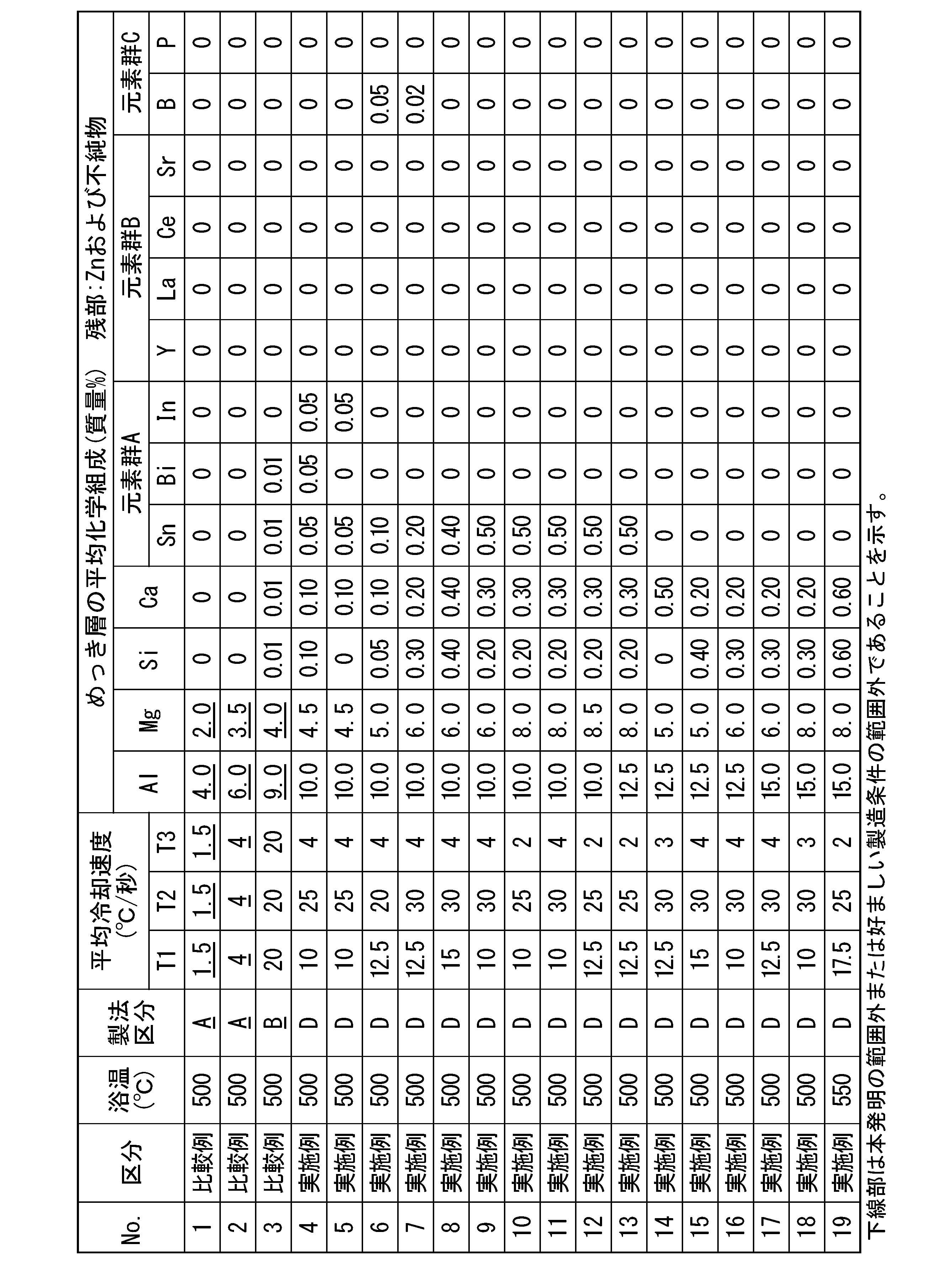


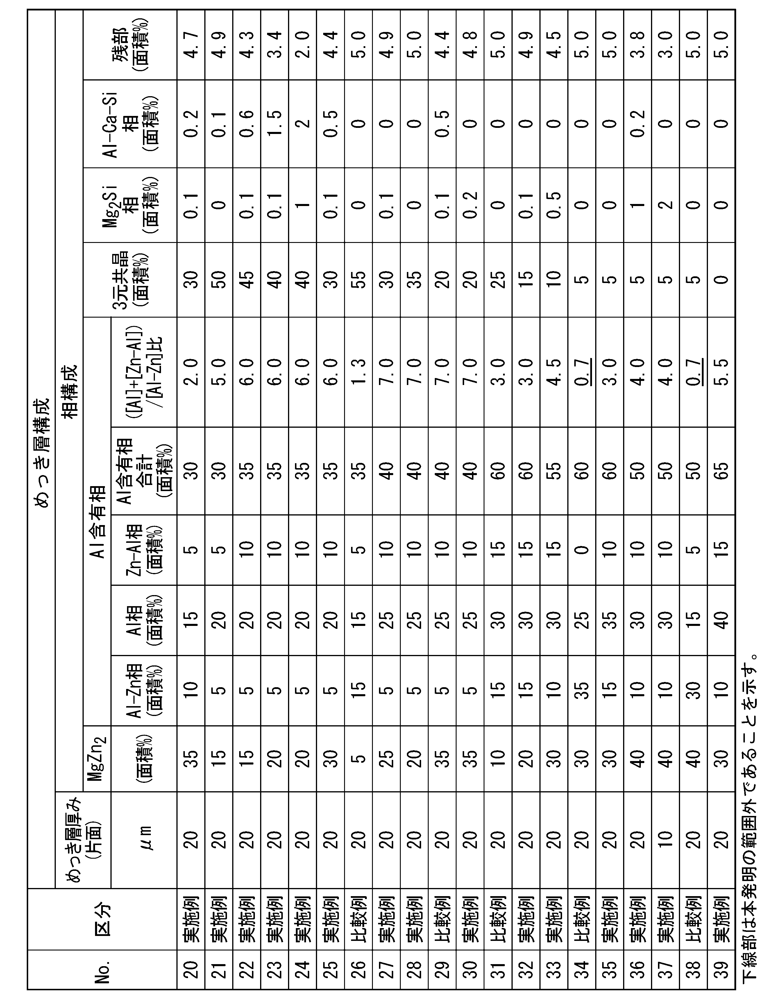

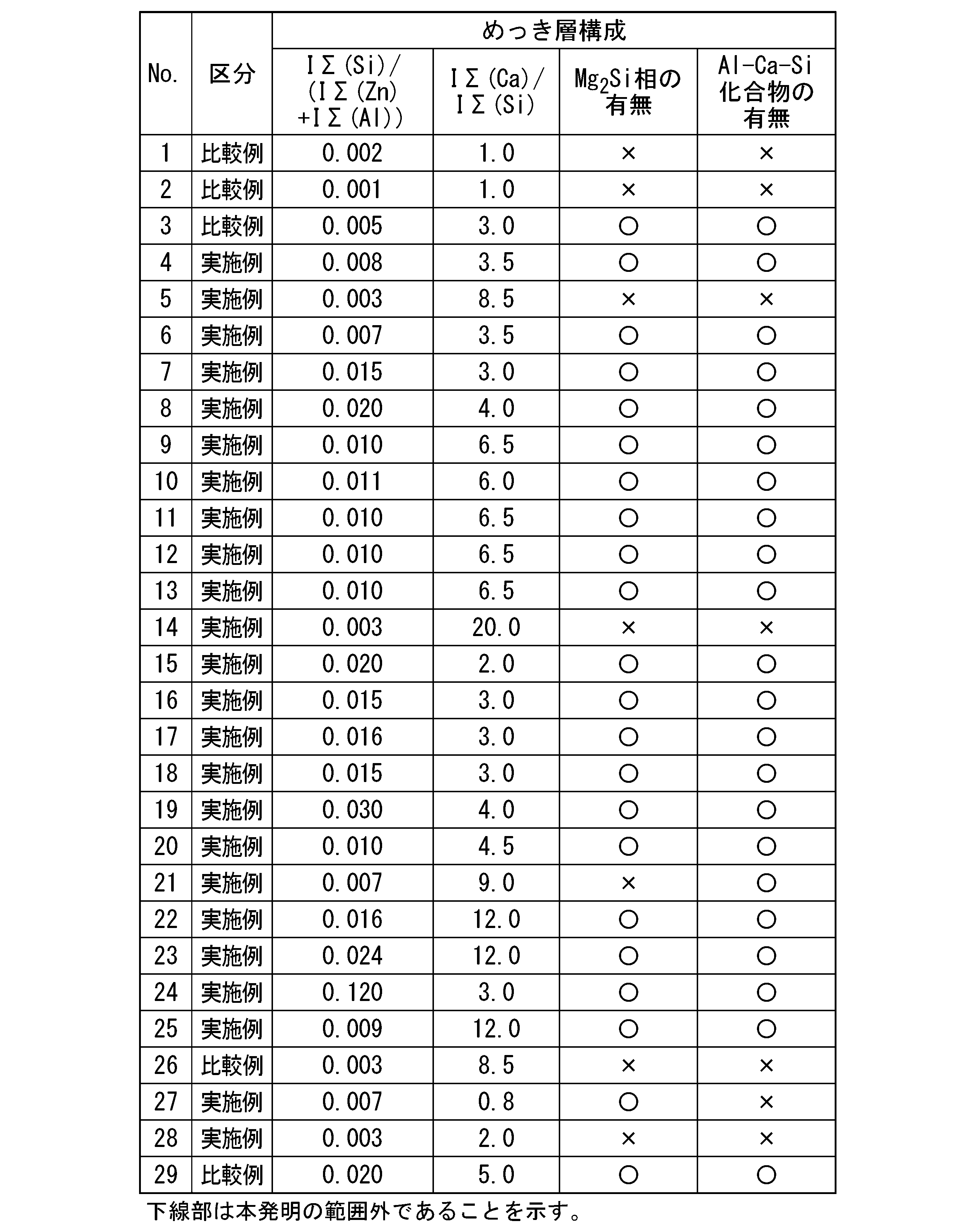
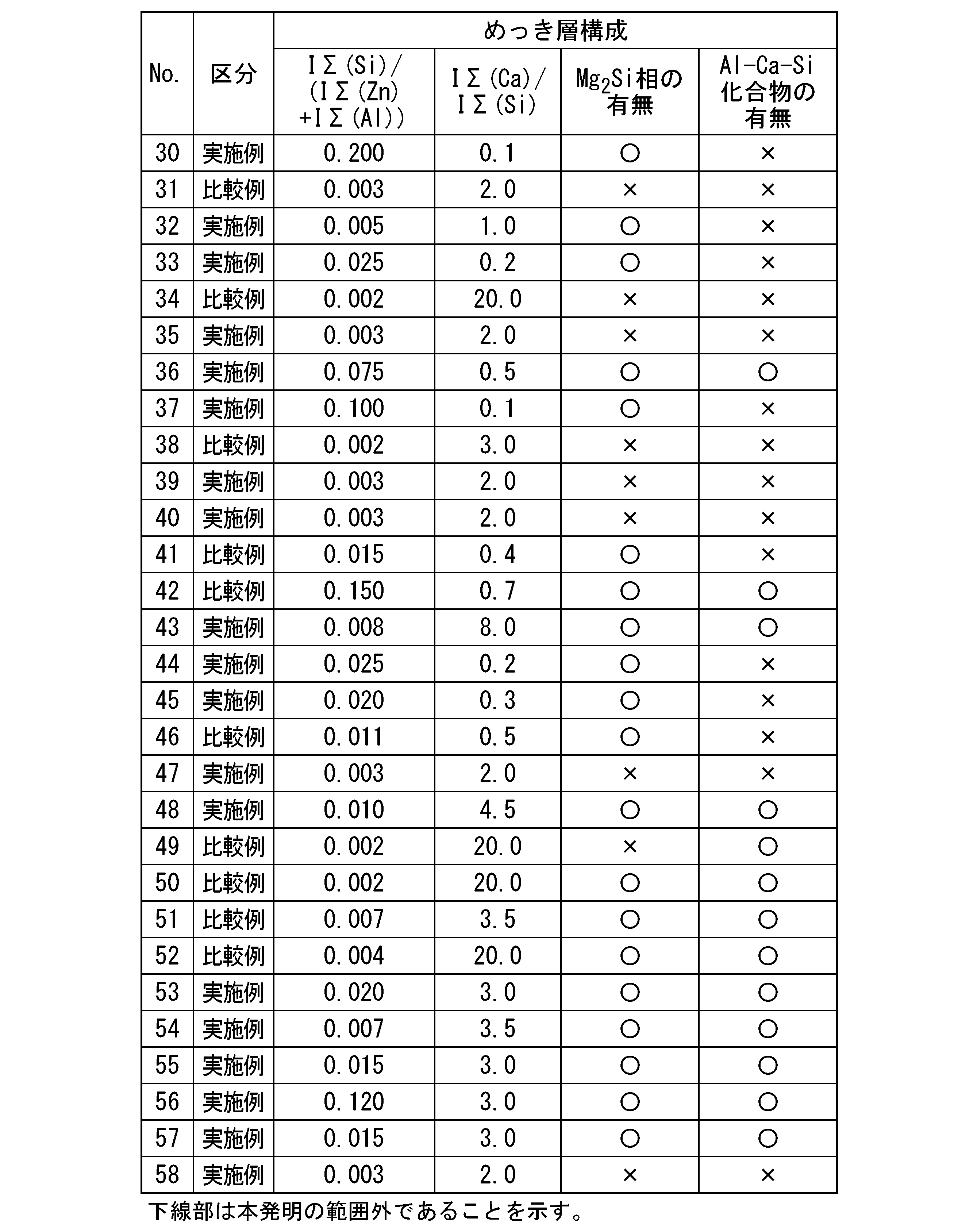
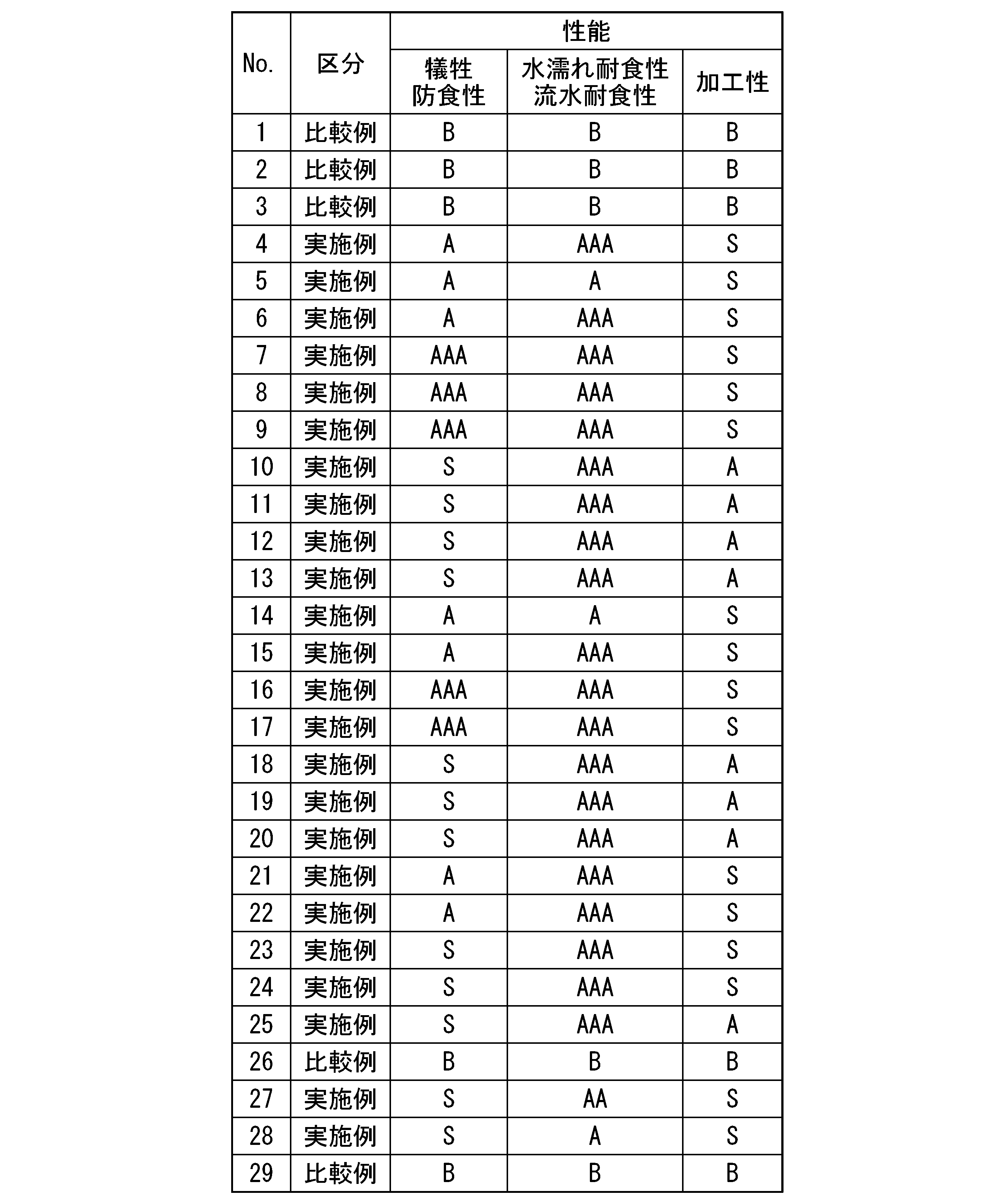
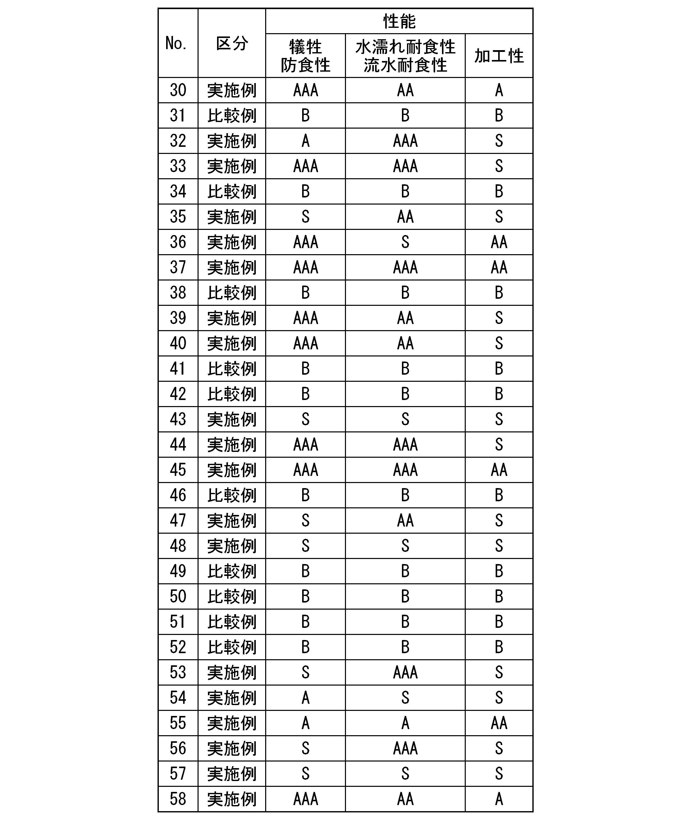
Claims (3)
- 鋼材と、前記鋼材の表面に配されためっき層とを有するめっき鋼材であって、
前記めっき層の平均化学組成が、質量%で、
Al:10.0%~40.0%、
Mg:4.0%超~8.5%、
Si:0%~5.0%、
Ca:0%~3.00%、
Sn:0%~3.00%、
Bi:0%~1.00%、
In:0%~1.00%、
Y :0%~0.50%、
La:0%~0.50%、
Ce:0%~0.50%、
Sr:0%~0.50%、
B :0%~1.00%、
P :0%~0.50%、
Cr:0%~0.25%、
Ti:0%~0.25%、
V :0%~0.25%、
Zr:0%~0.25%、
Ni:0%~1.00%、
Co:0%~0.25%、
Nb:0%~0.25%、
Cu:0%~1.00%、
Mn:0%~0.25%、
Mo:0%~0.25%、
W :0%~0.25%、
Ag:0%~1.00%、
Li:0%~0.50%、
Na:0%~0.05%、
K :0%~0.05%、
Fe:0%~5.00%、
Sb:0%~0.50%、
Pb:0%~0.50%、
Ba:0%~0.25%、
残部:Znおよび不純物、からなり、
前記鋼材の表面に対して垂直な前記めっき層の断面において、走査型電子顕微鏡で観察される組織が、面積分率で、
MgZn2相:10%以上50%以下、
Al相、Al-Zn相及びZn-Al相の合計:15%以上75%以下、
〔Al/MgZn2/Znの三元共晶組織〕:0%以上65%以下、
残部:0%以上5.0%以下、であり、
前記Al-Zn相に対する、前記Al相及び前記Zn-Al相の合計の面積比(([Al]+[Zn-Al])/[Al-Zn])が0.8以上である、めっき鋼材。 - 前記めっき層の平均化学組成において、Siが0.05%~5.0%であり、
前記めっき層の表面から深さ0.5μmまでの表層において、GDS法による深さ分析を行った場合の各元素の強度積算値が、下記式(1)を満足する、請求項1に記載のめっき鋼材。
IΣ(Si)/(IΣ(Zn)+IΣ(Al))≧0.005 …(1)
ただし、式(1)におけるIΣ(Si)、IΣ(Zn)およびIΣ(Al)はそれぞれ、GDS法により検出されたSi、ZnおよびAlの強度積算値である。 - 前記めっき層の平均化学組成において、Caが0.01%~3%であり、
めっき層中に、Ca3Al2Si2相、CaAl2Si2相、CaAl2Si2相、CaAl1-xSi1+x相(但し、x=0~0.2)のうちいずれか一つを含み、
前記めっき層の表面から深さ0.5μmまでの表層において、GDS法による深さ分析を行った場合の各元素の強度積算値が、下記式(2)を満足する、請求項1または請求項2に記載のめっき鋼材。
IΣ(Ca)/IΣ(Si)≧2.0 …(2)
ただし、式(2)におけるIΣ(Ca)およびIΣ(Si)はそれぞれ、GDS法により検出されたCaおよびSiの強度積算値である。
Priority Applications (10)
| Application Number | Priority Date | Filing Date | Title |
|---|---|---|---|
| CN202380061348.9A CN119744315A (zh) | 2022-08-30 | 2023-08-30 | 镀覆钢材 |
| US19/102,707 US20260055495A1 (en) | 2022-08-30 | 2023-08-30 | Plated steel material |
| AU2023334940A AU2023334940B2 (en) | 2022-08-30 | 2023-08-30 | Plated steel material |
| EP23860408.6A EP4582580A4 (en) | 2022-08-30 | 2023-08-30 | Plated steel material |
| PE2025000420A PE20250888A1 (es) | 2022-08-30 | 2023-08-30 | Material de acero enchapado |
| JP2024544326A JP7674695B2 (ja) | 2022-08-30 | 2023-08-30 | めっき鋼材 |
| KR1020257008695A KR20250053120A (ko) | 2022-08-30 | 2023-08-30 | 도금 강재 |
| JOJO/P/2025/0027A JOP20250027A1 (ar) | 2022-08-30 | 2025-02-04 | مادة فولاذية مطلية |
| MX2025001983A MX2025001983A (es) | 2022-08-30 | 2025-02-17 | Material de acero enchapado |
| CONC2025/0001902A CO2025001902A2 (es) | 2022-08-30 | 2025-02-20 | Material de acero enchapado |
Applications Claiming Priority (2)
| Application Number | Priority Date | Filing Date | Title |
|---|---|---|---|
| JP2022136497 | 2022-08-30 | ||
| JP2022-136497 | 2022-08-30 |
Publications (1)
| Publication Number | Publication Date |
|---|---|
| WO2024048646A1 true WO2024048646A1 (ja) | 2024-03-07 |
Family
ID=90099666
Family Applications (1)
| Application Number | Title | Priority Date | Filing Date |
|---|---|---|---|
| PCT/JP2023/031496 Ceased WO2024048646A1 (ja) | 2022-08-30 | 2023-08-30 | めっき鋼材 |
Country Status (12)
| Country | Link |
|---|---|
| US (1) | US20260055495A1 (ja) |
| EP (1) | EP4582580A4 (ja) |
| JP (1) | JP7674695B2 (ja) |
| KR (1) | KR20250053120A (ja) |
| CN (1) | CN119744315A (ja) |
| CL (1) | CL2025000515A1 (ja) |
| CO (1) | CO2025001902A2 (ja) |
| JO (1) | JOP20250027A1 (ja) |
| MX (1) | MX2025001983A (ja) |
| PE (1) | PE20250888A1 (ja) |
| TW (1) | TWI872671B (ja) |
| WO (1) | WO2024048646A1 (ja) |
Cited By (3)
| Publication number | Priority date | Publication date | Assignee | Title |
|---|---|---|---|---|
| WO2025121109A1 (ja) * | 2023-12-04 | 2025-06-12 | Jfeスチール株式会社 | 溶融Zn-Al-Mg系めっき鋼板 |
| WO2025230007A1 (ja) * | 2024-05-02 | 2025-11-06 | 日本製鉄株式会社 | 溶融Zn-Al-Mgめっき鋼材 |
| WO2025230005A1 (ja) * | 2024-05-02 | 2025-11-06 | 日本製鉄株式会社 | 溶融Zn-Al-Mgめっき鋼材 |
Citations (8)
| Publication number | Priority date | Publication date | Assignee | Title |
|---|---|---|---|---|
| JP2000265255A (ja) | 1999-03-16 | 2000-09-26 | Nisshin Steel Co Ltd | 耐熱性を改善した溶融Zn−Al系合金めっき鋼板およびその製造法 |
| JP2016166414A (ja) | 2015-03-02 | 2016-09-15 | Jfe鋼板株式会社 | 溶融Al−Zn−Mg−Siめっき鋼板とその製造方法 |
| WO2019049307A1 (ja) | 2017-09-08 | 2019-03-14 | 新日鐵住金株式会社 | Zn-Al-Mg系めっき鋼板 |
| JP2021195564A (ja) | 2020-06-09 | 2021-12-27 | 日本製鉄株式会社 | 溶融Zn−Al−Mg系めっき鋼材 |
| JP7052942B1 (ja) * | 2021-07-09 | 2022-04-12 | 日本製鉄株式会社 | めっき鋼材 |
| WO2022080004A1 (ja) * | 2020-10-16 | 2022-04-21 | 日本製鉄株式会社 | 溶融Zn系めっき鋼板 |
| WO2022107837A1 (ja) * | 2020-11-18 | 2022-05-27 | 日本製鉄株式会社 | めっき鋼材 |
| JP2022136497A (ja) | 2021-03-08 | 2022-09-21 | サンヨー綜合リース株式会社 | 既設杭撤去装置 |
Family Cites Families (1)
| Publication number | Priority date | Publication date | Assignee | Title |
|---|---|---|---|---|
| PL3575433T3 (pl) * | 2017-01-27 | 2024-05-06 | Nippon Steel Corporation | Powlekany produkt stalowy |
-
2023
- 2023-08-30 EP EP23860408.6A patent/EP4582580A4/en active Pending
- 2023-08-30 WO PCT/JP2023/031496 patent/WO2024048646A1/ja not_active Ceased
- 2023-08-30 PE PE2025000420A patent/PE20250888A1/es unknown
- 2023-08-30 JP JP2024544326A patent/JP7674695B2/ja active Active
- 2023-08-30 US US19/102,707 patent/US20260055495A1/en active Pending
- 2023-08-30 KR KR1020257008695A patent/KR20250053120A/ko active Pending
- 2023-08-30 CN CN202380061348.9A patent/CN119744315A/zh active Pending
- 2023-08-30 TW TW112132668A patent/TWI872671B/zh active
-
2025
- 2025-02-04 JO JOJO/P/2025/0027A patent/JOP20250027A1/ar unknown
- 2025-02-17 MX MX2025001983A patent/MX2025001983A/es unknown
- 2025-02-20 CO CONC2025/0001902A patent/CO2025001902A2/es unknown
- 2025-02-25 CL CL2025000515A patent/CL2025000515A1/es unknown
Patent Citations (8)
| Publication number | Priority date | Publication date | Assignee | Title |
|---|---|---|---|---|
| JP2000265255A (ja) | 1999-03-16 | 2000-09-26 | Nisshin Steel Co Ltd | 耐熱性を改善した溶融Zn−Al系合金めっき鋼板およびその製造法 |
| JP2016166414A (ja) | 2015-03-02 | 2016-09-15 | Jfe鋼板株式会社 | 溶融Al−Zn−Mg−Siめっき鋼板とその製造方法 |
| WO2019049307A1 (ja) | 2017-09-08 | 2019-03-14 | 新日鐵住金株式会社 | Zn-Al-Mg系めっき鋼板 |
| JP2021195564A (ja) | 2020-06-09 | 2021-12-27 | 日本製鉄株式会社 | 溶融Zn−Al−Mg系めっき鋼材 |
| WO2022080004A1 (ja) * | 2020-10-16 | 2022-04-21 | 日本製鉄株式会社 | 溶融Zn系めっき鋼板 |
| WO2022107837A1 (ja) * | 2020-11-18 | 2022-05-27 | 日本製鉄株式会社 | めっき鋼材 |
| JP2022136497A (ja) | 2021-03-08 | 2022-09-21 | サンヨー綜合リース株式会社 | 既設杭撤去装置 |
| JP7052942B1 (ja) * | 2021-07-09 | 2022-04-12 | 日本製鉄株式会社 | めっき鋼材 |
Non-Patent Citations (1)
| Title |
|---|
| See also references of EP4582580A4 |
Cited By (4)
| Publication number | Priority date | Publication date | Assignee | Title |
|---|---|---|---|---|
| WO2025121109A1 (ja) * | 2023-12-04 | 2025-06-12 | Jfeスチール株式会社 | 溶融Zn-Al-Mg系めっき鋼板 |
| JPWO2025121109A1 (ja) * | 2023-12-04 | 2025-06-12 | ||
| WO2025230007A1 (ja) * | 2024-05-02 | 2025-11-06 | 日本製鉄株式会社 | 溶融Zn-Al-Mgめっき鋼材 |
| WO2025230005A1 (ja) * | 2024-05-02 | 2025-11-06 | 日本製鉄株式会社 | 溶融Zn-Al-Mgめっき鋼材 |
Also Published As
| Publication number | Publication date |
|---|---|
| JOP20250027A1 (ar) | 2025-02-04 |
| CL2025000515A1 (es) | 2025-05-16 |
| EP4582580A1 (en) | 2025-07-09 |
| EP4582580A4 (en) | 2025-11-26 |
| US20260055495A1 (en) | 2026-02-26 |
| TWI872671B (zh) | 2025-02-11 |
| JP7674695B2 (ja) | 2025-05-12 |
| CO2025001902A2 (es) | 2025-03-06 |
| TW202413668A (zh) | 2024-04-01 |
| PE20250888A1 (es) | 2025-03-28 |
| AU2023334940A1 (en) | 2025-02-27 |
| CN119744315A (zh) | 2025-04-01 |
| JPWO2024048646A1 (ja) | 2024-03-07 |
| KR20250053120A (ko) | 2025-04-21 |
| MX2025001983A (es) | 2025-04-02 |
Similar Documents
| Publication | Publication Date | Title |
|---|---|---|
| JP7315826B2 (ja) | めっき鋼材、およびめっき鋼材の製造方法 | |
| KR102527548B1 (ko) | 도금 강재 | |
| JP7674695B2 (ja) | めっき鋼材 | |
| CN116685706B (zh) | 镀覆钢材 | |
| JP7549965B2 (ja) | 溶融Al-Zn-Mg-Si系めっき鋼板及びその製造方法、並びに、塗装鋼板及びその製造方法 | |
| JP7590687B1 (ja) | 溶融めっき鋼材 | |
| TWI912715B (zh) | 鍍敷鋼材 | |
| TWI826270B (zh) | 熔融鍍敷鋼板 | |
| JP7417103B2 (ja) | 溶融Zn-Al-Mg系めっき鋼材 | |
| AU2023334940B2 (en) | Plated steel material | |
| JP7653049B1 (ja) | 溶融めっき鋼材 | |
| TWI889485B (zh) | 鍍敷鋼材 | |
| TWI876928B (zh) | 熔融鍍敷鋼材 | |
| CN121002225A (zh) | 热浸镀钢材 |
Legal Events
| Date | Code | Title | Description |
|---|---|---|---|
| 121 | Ep: the epo has been informed by wipo that ep was designated in this application |
Ref document number: 23860408 Country of ref document: EP Kind code of ref document: A1 |
|
| WWE | Wipo information: entry into national phase |
Ref document number: 2024544326 Country of ref document: JP |
|
| WWE | Wipo information: entry into national phase |
Ref document number: DZP2025000095 Country of ref document: DZ |
|
| WWE | Wipo information: entry into national phase |
Ref document number: AU2023334940 Country of ref document: AU |
|
| REG | Reference to national code |
Ref country code: BR Ref legal event code: B01A Ref document number: 112025002047 Country of ref document: BR |
|
| WWE | Wipo information: entry into national phase |
Ref document number: 818655 Country of ref document: NZ |
|
| WWE | Wipo information: entry into national phase |
Ref document number: MX/A/2025/001983 Country of ref document: MX |
|
| WWE | Wipo information: entry into national phase |
Ref document number: 202517013755 Country of ref document: IN |
|
| WWE | Wipo information: entry into national phase |
Ref document number: 202380061348.9 Country of ref document: CN |
|
| WWE | Wipo information: entry into national phase |
Ref document number: P2025-00563 Country of ref document: AE |
|
| WWE | Wipo information: entry into national phase |
Ref document number: 2501001229 Country of ref document: TH |
|
| ENP | Entry into the national phase |
Ref document number: 2023334940 Country of ref document: AU Date of ref document: 20230830 Kind code of ref document: A |
|
| WWP | Wipo information: published in national office |
Ref document number: 818655 Country of ref document: NZ |
|
| WWP | Wipo information: published in national office |
Ref document number: 202517013755 Country of ref document: IN |
|
| ENP | Entry into the national phase |
Ref document number: 20257008695 Country of ref document: KR Kind code of ref document: A |
|
| WWE | Wipo information: entry into national phase |
Ref document number: 1020257008695 Country of ref document: KR |
|
| WWE | Wipo information: entry into national phase |
Ref document number: 11202501008P Country of ref document: SG |
|
| WWP | Wipo information: published in national office |
Ref document number: 11202501008P Country of ref document: SG |
|
| WWE | Wipo information: entry into national phase |
Ref document number: 2023860408 Country of ref document: EP |
|
| NENP | Non-entry into the national phase |
Ref country code: DE |
|
| WWP | Wipo information: published in national office |
Ref document number: 202380061348.9 Country of ref document: CN |
|
| WWP | Wipo information: published in national office |
Ref document number: MX/A/2025/001983 Country of ref document: MX |
|
| ENP | Entry into the national phase |
Ref document number: 2023860408 Country of ref document: EP Effective date: 20250331 |
|
| WWP | Wipo information: published in national office |
Ref document number: 1020257008695 Country of ref document: KR |
|
| ENP | Entry into the national phase |
Ref document number: 112025002047 Country of ref document: BR Kind code of ref document: A2 Effective date: 20250131 |
|
| WWP | Wipo information: published in national office |
Ref document number: 2023860408 Country of ref document: EP |