WO2024053335A1 - イヤホン - Google Patents
イヤホン Download PDFInfo
- Publication number
- WO2024053335A1 WO2024053335A1 PCT/JP2023/029306 JP2023029306W WO2024053335A1 WO 2024053335 A1 WO2024053335 A1 WO 2024053335A1 JP 2023029306 W JP2023029306 W JP 2023029306W WO 2024053335 A1 WO2024053335 A1 WO 2024053335A1
- Authority
- WO
- WIPO (PCT)
- Prior art keywords
- unit
- cap
- wall
- acoustic tube
- diaphragm
- Prior art date
- Legal status (The legal status is an assumption and is not a legal conclusion. Google has not performed a legal analysis and makes no representation as to the accuracy of the status listed.)
- Ceased
Links
Images



Classifications
-
- H—ELECTRICITY
- H04—ELECTRIC COMMUNICATION TECHNIQUE
- H04R—LOUDSPEAKERS, MICROPHONES, GRAMOPHONE PICK-UPS OR LIKE ACOUSTIC ELECTROMECHANICAL TRANSDUCERS; ELECTRIC HEARING AIDS; PUBLIC ADDRESS SYSTEMS
- H04R1/00—Details of transducers, loudspeakers or microphones
- H04R1/10—Earpieces; Attachments therefor ; Earphones; Monophonic headphones
- H04R1/1058—Manufacture or assembly
- H04R1/1075—Mountings of transducers in earphones or headphones
-
- H—ELECTRICITY
- H04—ELECTRIC COMMUNICATION TECHNIQUE
- H04R—LOUDSPEAKERS, MICROPHONES, GRAMOPHONE PICK-UPS OR LIKE ACOUSTIC ELECTROMECHANICAL TRANSDUCERS; ELECTRIC HEARING AIDS; PUBLIC ADDRESS SYSTEMS
- H04R1/00—Details of transducers, loudspeakers or microphones
- H04R1/10—Earpieces; Attachments therefor ; Earphones; Monophonic headphones
- H04R1/1016—Earpieces of the intra-aural type
-
- H—ELECTRICITY
- H04—ELECTRIC COMMUNICATION TECHNIQUE
- H04R—LOUDSPEAKERS, MICROPHONES, GRAMOPHONE PICK-UPS OR LIKE ACOUSTIC ELECTROMECHANICAL TRANSDUCERS; ELECTRIC HEARING AIDS; PUBLIC ADDRESS SYSTEMS
- H04R1/00—Details of transducers, loudspeakers or microphones
- H04R1/20—Arrangements for obtaining desired frequency or directional characteristics
- H04R1/22—Arrangements for obtaining desired frequency or directional characteristics for obtaining desired frequency characteristic only
- H04R1/28—Transducer mountings or enclosures modified by provision of mechanical or acoustic impedances, e.g. resonator, damping means
- H04R1/2807—Enclosures comprising vibrating or resonating arrangements
- H04R1/2815—Enclosures comprising vibrating or resonating arrangements of the bass reflex type
- H04R1/2823—Vents, i.e. ports, e.g. shape thereof or tuning thereof with damping material
- H04R1/2826—Vents, i.e. ports, e.g. shape thereof or tuning thereof with damping material for loudspeaker transducers
-
- H—ELECTRICITY
- H04—ELECTRIC COMMUNICATION TECHNIQUE
- H04R—LOUDSPEAKERS, MICROPHONES, GRAMOPHONE PICK-UPS OR LIKE ACOUSTIC ELECTROMECHANICAL TRANSDUCERS; ELECTRIC HEARING AIDS; PUBLIC ADDRESS SYSTEMS
- H04R2460/00—Details of hearing devices, i.e. of ear- or headphones covered by H04R1/10 or H04R5/033 but not provided for in any of their subgroups, or of hearing aids covered by H04R25/00 but not provided for in any of its subgroups
- H04R2460/11—Aspects relating to vents, e.g. shape, orientation, acoustic properties in ear tips of hearing devices to prevent occlusion
Definitions
- the present invention relates to earphones.
- Earplug-shaped canal headphones that are inserted into the ear canal are known.
- the driver unit has an opening that emits sound waves output from the driver unit into the ear, and an end of the driver unit sound emitting side of the cylindrical support member with the outer surface of the cylindrical support member exposed.
- An earphone is known that includes a sound emitting member attached to the edge, and a lid member attached to the edge of the cylindrical support member on the side opposite to the driver unit sound emission side with the outer surface of the cylindrical support member exposed. (For example, see Patent Document 1).
- a small driver unit can be installed in the ear canal, so by placing the diaphragm close to the eardrum, loss of low-frequency sound can be reduced even if the area of the diaphragm is small. be able to.
- the pressure applied to the diaphragm when inserting the earphone into the ear may deform or crush the diaphragm.
- the prior art documents do not disclose techniques for solving such problems.
- An object of the present invention is to provide earphones with high sound quality while reducing pressure on the diaphragm.
- the earphone according to the present invention includes a diaphragm, a driver unit having the diaphragm on the front surface, a unit cap that accommodates the driver unit, and a front air chamber connected to the front surface of the unit cap, and a front air chamber in the front surface of the diaphragm.
- a sound pipe forming an acoustic tube the unit cap includes a unit holding wall that holds a side wall of the driver unit; and a unit holding wall that holds a side wall of the driver unit;
- a communication hole communicating the front surface and the rear surface is provided, and the central axis of the unit accommodating portion defined by the unit holding wall is eccentric from the central axis of the unit cap.
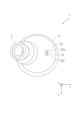
- FIG. 1 is a schematic front view showing an embodiment of an earphone according to the present invention, with the housing removed.
- FIG. FIG. 3 is a schematic vertical cross-sectional view of the earphone.
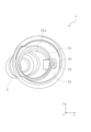
- FIG. 3 is a schematic bottom view of the earphone. It is a schematic plan view of the housing
- the axial direction of the driver unit 5 is also referred to as the z direction, and the directions orthogonal to the z direction are also referred to as the x direction and the y direction.
- the surface facing the +z direction is also referred to as the rear surface, and the surface facing the ⁇ z direction is also referred to as the front surface.
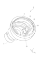
- the earphone 1 mainly includes a unit cap 2, an acoustic tube 3, and a housing 4 in appearance.
- the unit cap 2 is a bottomed cylindrical member having a bottom on the front side.
- the acoustic tube 3 is a substantially cylindrical member connected to the front surface of the unit cap 2.
- the acoustic tube 3 extends obliquely to the axis of the unit cap 2.
- a ventilation hole 25 (see FIG. 2) is formed at the connecting portion between the unit cap 2 and the acoustic tube 3, and the interior space of the unit cap 2 and the interior space of the acoustic tube 3 are communicated through this ventilation hole 25. .
- the unit cap 2 mainly includes a unit holding wall 21, a communication hole 22, a rear chamber wall 23, a notch 24, and a ventilation hole 25.
- the unit holding wall 21 is a cylindrical member formed inside the unit cap 2.
- the unit holding wall 21 holds the side wall of the driver unit 5. That is, the inner space of the unit holding wall 21 serves as a unit accommodating portion 21a that accommodates the driver unit 5. Since the driver unit 5 is fitted into the unit accommodating portion 21a with almost no gap, the central axis of the driver unit 5 is approximately at the same position as the central axis 21x of the unit accommodating portion 21a.
- a diaphragm 6 is arranged on the front side of the driver unit 5.
- the front side of the diaphragm 6 is connected to the inner space of the acoustic tube 3 via a ventilation hole 25.
- the inner space of the acoustic tube 3 becomes a front air chamber 3s.
- the central axis 21x of the unit accommodating portion 21a defined by the unit holding wall 21 is eccentric from the central axis 2x of the unit cap 2. According to this configuration, compared to a configuration in which the driver unit 5 is disposed at the center of the unit cap 2 in the axial direction, it is possible to form the space 2s on the side of the driver unit 5 even if the unit cap 2 is small. can.
- a communication hole 22 is formed in the unit cap 2 in front of the unit holding wall 21.
- the communication hole 22 is a through hole that communicates the front and rear surfaces of the unit cap 2.
- the communication hole 22 is formed on the front surface of the unit cap 2, and on a wall surface that partitions the space 2s. That is, the communication hole 22 is formed on the opposite side of the acoustic tube 3 in the radial direction of the unit cap 2 .
- the communication hole 22 is formed across the inside and outside of the unit holding wall 21 in the radial direction. As a result, the inside and outside of the unit holding wall 21 are communicated with each other via the communication hole 22 and the front space outside the unit cap 2. Furthermore, a stepped portion 22a is formed by cutting out a portion of the thickness of the unit cap 2 at the upper and lower ends of the communication hole 22 in the y direction (see FIG. 3), and the stepped portion 22a can be formed into an appropriate shape. You may adjust the amount of ventilation and how the air escapes.
- the position of the communication hole 22 in the drawings is an example, and it is needless to say that it is not limited to a configuration in which it is disposed in a longitudinal section passing through approximately the center of the acoustic tube 3 as shown in FIG.
- the communication hole 22 may be formed across the inside and outside of the unit holding wall 21 in the radial direction, and may be arranged above or below the position in FIG. 4 along the curved surface of the unit holding wall 21. may be set. In that case, the communication hole 22 is arranged to the left of the position in FIG. 4 according to the curvature of the unit holding wall 21.
- a rear chamber wall 23 is provided in the space 2s.
- the rear chamber wall 23 is a partially cylindrical body disposed on the radially outer side of the unit holding wall 21 .
- the rear chamber wall 23 has a U-shape in plan view (see FIG. 4). Further, the space inside the rear chamber wall 23 communicates with the communication hole 22. As a result, the space surrounded by the rear chamber wall 23 and the unit holding wall 21 becomes a rear air chamber 23s that communicates with the front air chamber 3s via the communication hole 22.
- the air pressure generated when the earphone 1 is attached to the ear canal escapes from the front air chamber 3s through the communication hole 22. Further, according to the above-described configuration, air flows through the communication holes 22 even in response to pressure in the direction of pulling the diaphragm 6 that occurs when removing the diaphragm 6 and pressure changes that occur when taking it out of the packaging. Therefore, even in a small earphone with a small space between the diaphragm 6 and the eardrum, changes in air pressure applied to the front surface of the diaphragm 6 can be reduced. In turn, deformation and damage to the diaphragm 6 can be prevented. Furthermore, it is possible to similarly reduce changes in air pressure that occur not only during installation but also during packaging and transportation.
- the inflow and outflow of air is controlled, so that low-frequency sound pressure can be ensured.
- a housing 4 that covers the rear surface of the driver unit 5 is connected to the rear surface of the unit cap 2 .
- the space 4s inside the housing 4 communicates with the rear air chamber 23s. According to this configuration, air vibrations in the rear air chamber 23s can also be transmitted to the space 4s.
- the housing 4 is provided with a communication hole (not shown) that communicates with the outside air, the housing 4 is not provided with the communication hole, and the inside of the housing 4 is communicated with the outside air through only one communication hole 22.
- the configuration may be such that the space 4s and the rear air chamber 23s communicate with the outside air.
- a configuration may be adopted in which the rear chamber wall 23 is not provided. In this case, the space 4s and the space 2s inside the housing 4 communicate with the outside air through the communication hole 22.
- the notch 24 is formed by cutting out the wall surface around the communication hole 22, that is, a part of the unit holding wall 21 and the inner wall of the front surface of the unit cap 2 in the thickness direction. has been done.
- the cutout portion 24 has a shape in which the unit holding wall 21 and the unit cap 2 are cut out in a substantially L-shape when viewed in longitudinal section.
- the notch portion 24 has a shape obtained by cutting out the unit holding wall 21 in a rectangular shape. Note that the detailed aspects are not limited to those described above.
- the acoustic resistance material 7 is accommodated in the notch 24.
- the acoustic resistance material 7 is arranged along the notch 24 in a substantially L-shape.
- the acoustic resistance material 7 covers at least a portion of the communication hole 22. More specifically, the acoustic resistance material 7 is interposed between the unit accommodating portion 21 a and the front space of the unit cap 2 in the communication hole 22 . That is, the front air chamber 3s and the rear air chamber 23s communicate with each other via the acoustic resistance material 7.
- the acoustic tube 3 is connected at a position eccentric to the central axis 21x side of the unit accommodating portion 21a with respect to the axial center of the unit cap 2. That is, the front air chamber 3s formed by the acoustic tube 3 is formed on the front side of the driver unit 5. Therefore, the vibration of the diaphragm 6 is transmitted from the front surface of the diaphragm 6 to the front air chamber 3s.
- vibration has the property of progressing linearly as the frequency becomes higher.
- the diaphragm 6 faces the front air chamber 3s through the ventilation hole 25, so that the sound in the middle and high ranges is suppressed. Vibrations can be sufficiently transmitted to the opening of the acoustic tube 3. That is, according to this configuration, although the earphone is small, it is possible to reproduce sound sources in the middle and high ranges with high sound quality.
- the acoustic tube 3 may be arranged at a position where the virtual straight line 3x along the central axis of the acoustic tube 3 passes through the center of the ventilation hole 25.
- the ventilation hole 25 is sufficiently opened to the front air chamber 3s constituted by the acoustic tube 3, and the vibration of the diaphragm 6 is linearly transmitted to the front air chamber 3s, so that the Even with the earphones 1, it is possible to reproduce sound sources in the middle and high ranges with even higher sound quality.
- the central axis 21x of the unit accommodating portion 21a is drawn approximately parallel to the central axis 2x of the unit cap 2. That is, the central axis of the driver unit 5 is substantially parallel to the central axis 2x of the unit cap 2.
- the technical scope of the present invention is not limited to this, and the central axis 21x of the unit accommodating portion 21a may be formed to be inclined with respect to the central axis 2x of the unit cap 2. That is, the driver unit 5 may be housed at an angle with respect to the central axis 2x of the unit cap 2.
- the acoustic tube 3 may be connected obliquely to the front surface of the unit cap 2, and the driver unit 5 may be housed inclined in the axial direction of the acoustic tube 3.
- the central axis 21x of the unit accommodating portion 21a and the central axis of the driver unit 5 may be substantially parallel to the imaginary straight line 3x along the central axis of the acoustic tube 3.
- the driver unit 5 and the diaphragm 6 directly face the ventilation hole 25 and the front air chamber 3s formed inside the acoustic tube 3.
- the earphone can be made smaller while maintaining the sound quality, so it is possible to realize an earphone with a thinner acoustic tube than before. Therefore, according to the configuration according to the present invention, it is possible to realize an earphone suitable for users with small ears or narrow ear canals.
- FIG. 6 shows the frequency characteristics of the earphones. That is, the horizontal axis represents frequency, and the vertical axis represents output level (dBV).
- the broken line indicates the frequency characteristic of the earphone according to the related technology, and the solid line indicates the frequency characteristic of the earphone 1 according to the present invention.
- FIG. 6 the frequency characteristics of earphones of related technology are shown in a superimposed manner.
- the related art earphone has a structure in which the driver unit is housed approximately in the axial center of the unit cap, and does not have a configuration corresponding to the space 2s. Furthermore, the acoustic tube of the related art earphone is connected to the axial center of the unit cap.
- the earphone 1 maintains sound pressure better than related technology earphones in the low frequency band F1 exceeding 1 kHz. That is, the earphone 1 can reproduce low-frequency sound with high quality even though the unit cap 2 has a small external shape. Furthermore, in the high frequency band F2, which is a higher frequency band than the low frequency band F1, the fluctuation width of the sound pressure is smaller than in earphones of related technology. That is, the earphone 1 can output stably even in high frequencies.
- Earphone 2 Unit cap 21 Unit holding wall 21a Unit accommodating part 21x Central axis 22 of unit accommodating part Communication hole 23 Rear chamber wall 23s Rear air chamber 3 Acoustic tube 3s Front air chamber 4 Housing 5 Driver unit 6 Vibration plate
Landscapes
- Engineering & Computer Science (AREA)
- Physics & Mathematics (AREA)
- Acoustics & Sound (AREA)
- Signal Processing (AREA)
- Manufacturing & Machinery (AREA)
- Headphones And Earphones (AREA)
Abstract
Description
図1に示すように、イヤホン1は外観上、主として、ユニットキャップ2と、音響管3と、ハウジング4と、を有する。ユニットキャップ2は、前面側に底を有する有底円筒状の部材である。音響管3は、ユニットキャップ2の前面に連結される略円筒状の部材である。音響管3は、ユニットキャップ2の軸に対して斜めに伸び出ている。ユニットキャップ2と音響管3との連結部分は通気孔25(図2参照)が形成されており、この通気孔25により、ユニットキャップ2の内側空間と音響管3の内側空間は連通している。
なお、連通孔22の図面上の位置は例示であり、図2のように音響管3の略中央を通る縦断面に配設される構成には限定されないのは勿論である。連通孔22は、ユニット保持壁21の半径方向内側および外側にまたがって形成されていればよく、ユニット保持壁21の湾曲面に沿って、図4中の位置よりも図中上方又は下方に配設されていてもよい。その場合、連通孔22は、ユニット保持壁21の湾曲に応じて図4中の位置よりも図中左方に配設される。
また、後室壁23を備えない構成であってもよい。この場合、ハウジング4の内側の空間4sおよび空間2sが、連通孔22を介して外気と連通する。
図6は、イヤホンの周波数特性を示している。すなわち横軸は周波数を、縦軸は出力レベル(dBV)を示している。破線は、関連技術に係るイヤホンの周波数特性を示しており、実線は、本発明に係るイヤホン1の周波数特性を示している。また、図6には、関連技術のイヤホンの周波数特性が重畳して示されている。関連技術のイヤホンは、ドライバユニットがユニットキャップの軸方向略中心に収容され、空間2sに対応する構成を有さない構造である。また、関連技術のイヤホンの音響管は、ユニットキャップの軸方向中心に連結されている。
以上、本発明を実施の形態を用いて説明したが、本発明の技術的範囲は上記実施の形態に記載の範囲には限定されず、その要旨の範囲内で種々の変形及び変更が可能である。
2 ユニットキャップ
21 ユニット保持壁
21a ユニット収容部
21x ユニット収容部の中心軸
22 連通孔
23 後室壁
23s 後側空気室
3 音響管
3s 前側空気室
4 ハウジング
5 ドライバユニット
6 振動板
Claims (8)
- 振動板と、
前記振動板を前面に備えるドライバユニットと、
前記ドライバユニットを収容するユニットキャップと、
前記ユニットキャップの前面に連結され、前記振動板の前面に前側空気室を形成する音響管と、
を備え、
前記ユニットキャップは、
前記ドライバユニットの側壁を保持するユニット保持壁と、
前記ユニット保持壁の前方において、前記ユニット保持壁の内側と外側、および前記ユニットキャップの前面と後面とを連通する連通孔と、
を備え、
前記ユニット保持壁により規定されるユニット収容部の中心軸は、前記ユニットキャップの中心軸から偏心している、
イヤホン。
- 前記音響管は、前記ユニットキャップの軸方向の中心に対して、前記ユニット保持壁の中心軸側に偏心した位置に連結されている、
請求項1記載のイヤホン。
- 前記音響管は前記ユニットキャップの前記前面に対して斜めに連結され、
前記ドライバユニットは前記音響管の軸方向に傾斜して収容されていて、前記音響管内部に形成される前記前側空気室に正対する、
請求項1記載のイヤホン。
- 前記ユニットキャップと前記音響管との連結部分には、前記振動板と前記前側空気室とを連通する通気孔が形成され、前記音響管の中心軸に沿う仮想直線は、前記通気孔の中心を通る、
請求項1乃至3のいずれかに記載のイヤホン。
- 前記連通孔は、前記ユニットキャップの半径方向において、前記音響管とは反対側に形成されている、
請求項1記載のイヤホン。
- 前記ユニットキャップは、前記ユニットキャップの後面側であって前記ユニット保持壁の半径方向外側に配設され、前記連通孔と連通する後側空気室を形成する後室壁をさらに備える、
請求項1記載のイヤホン。
- 前記ユニットキャップの後面には、前記ドライバユニットの後面を覆うハウジングが連結され、前記ハウジングの内側の空間は、前記後側空気室と連通する、
請求項6記載のイヤホン。
- 少なくとも、前記ユニット保持壁の前端部および前記ユニットキャップの前面の内壁のいずれかには、前記ユニット保持壁又は前記内壁を厚さ方向に切欠いた切欠部が形成され、
前記切欠部には音響抵抗材が収容され、
前記前側空気室と前記後側空気室とは、前記音響抵抗材を介して連通している、
請求項6記載のイヤホン。
Priority Applications (5)
| Application Number | Priority Date | Filing Date | Title |
|---|---|---|---|
| EP23861655.1A EP4387267A4 (en) | 2022-09-06 | 2023-08-10 | Earphone |
| JP2023569709A JP7621692B2 (ja) | 2022-09-06 | 2023-08-10 | イヤホン |
| CN202380012446.3A CN117999799A (zh) | 2022-09-06 | 2023-08-10 | 耳机 |
| US18/691,126 US20250150747A1 (en) | 2022-09-06 | 2023-08-10 | Earphone |
| JP2025002409A JP2025063897A (ja) | 2022-09-06 | 2025-01-07 | イヤホン |
Applications Claiming Priority (2)
| Application Number | Priority Date | Filing Date | Title |
|---|---|---|---|
| JP2022-141588 | 2022-09-06 | ||
| JP2022141588 | 2022-09-06 |
Publications (1)
| Publication Number | Publication Date |
|---|---|
| WO2024053335A1 true WO2024053335A1 (ja) | 2024-03-14 |
Family
ID=90191057
Family Applications (1)
| Application Number | Title | Priority Date | Filing Date |
|---|---|---|---|
| PCT/JP2023/029306 Ceased WO2024053335A1 (ja) | 2022-09-06 | 2023-08-10 | イヤホン |
Country Status (5)
| Country | Link |
|---|---|
| US (1) | US20250150747A1 (ja) |
| EP (1) | EP4387267A4 (ja) |
| JP (2) | JP7621692B2 (ja) |
| CN (1) | CN117999799A (ja) |
| WO (1) | WO2024053335A1 (ja) |
Citations (3)
| Publication number | Priority date | Publication date | Assignee | Title |
|---|---|---|---|---|
| JP2015109542A (ja) * | 2013-12-04 | 2015-06-11 | パナソニックIpマネジメント株式会社 | スピーカ、イヤホン、及び補聴装置 |
| JP2017158045A (ja) | 2016-03-02 | 2017-09-07 | 株式会社オーディオテクニカ | ヘッドホン |
| JP2019033365A (ja) * | 2017-08-08 | 2019-02-28 | 株式会社Jvcケンウッド | イヤホンにおける通気路形成構造及びイヤホン |
Family Cites Families (5)
| Publication number | Priority date | Publication date | Assignee | Title |
|---|---|---|---|---|
| JP5666797B2 (ja) * | 2009-10-05 | 2015-02-12 | フォスター電機株式会社 | イヤホン |
| GB2493206B (en) * | 2011-07-29 | 2013-10-02 | Incus Lab Ltd | Earphone arrangements |
| EP2809082A1 (en) * | 2013-05-28 | 2014-12-03 | AKG Acoustics GmbH | Plug earphone or concha earphone |
| JP6563327B2 (ja) * | 2015-12-17 | 2019-08-21 | 株式会社オーディオテクニカ | イヤホン |
| JP6866808B2 (ja) * | 2017-09-06 | 2021-04-28 | 株式会社Jvcケンウッド | イヤホン |
-
2023
- 2023-08-10 US US18/691,126 patent/US20250150747A1/en active Pending
- 2023-08-10 CN CN202380012446.3A patent/CN117999799A/zh active Pending
- 2023-08-10 EP EP23861655.1A patent/EP4387267A4/en active Pending
- 2023-08-10 JP JP2023569709A patent/JP7621692B2/ja active Active
- 2023-08-10 WO PCT/JP2023/029306 patent/WO2024053335A1/ja not_active Ceased
-
2025
- 2025-01-07 JP JP2025002409A patent/JP2025063897A/ja active Pending
Patent Citations (3)
| Publication number | Priority date | Publication date | Assignee | Title |
|---|---|---|---|---|
| JP2015109542A (ja) * | 2013-12-04 | 2015-06-11 | パナソニックIpマネジメント株式会社 | スピーカ、イヤホン、及び補聴装置 |
| JP2017158045A (ja) | 2016-03-02 | 2017-09-07 | 株式会社オーディオテクニカ | ヘッドホン |
| JP2019033365A (ja) * | 2017-08-08 | 2019-02-28 | 株式会社Jvcケンウッド | イヤホンにおける通気路形成構造及びイヤホン |
Non-Patent Citations (1)
| Title |
|---|
| See also references of EP4387267A4 |
Also Published As
| Publication number | Publication date |
|---|---|
| US20250150747A1 (en) | 2025-05-08 |
| JPWO2024053335A1 (ja) | 2024-03-14 |
| EP4387267A4 (en) | 2025-01-22 |
| EP4387267A1 (en) | 2024-06-19 |
| JP7621692B2 (ja) | 2025-01-27 |
| CN117999799A (zh) | 2024-05-07 |
| JP2025063897A (ja) | 2025-04-16 |
Similar Documents
| Publication | Publication Date | Title |
|---|---|---|
| US11750966B2 (en) | Earphone having a controlled acoustic leak port | |
| US10959005B2 (en) | Headphone | |
| JP5695703B2 (ja) | 音響チューニングメカニズムを有するイヤホン | |
| CN102196330B (zh) | 耳机 | |
| CN105228039A (zh) | 具有通风室的质量加载耳塞 | |
| CN110972013A (zh) | 耳罩结构 | |
| CN204681561U (zh) | 内耳甲式耳机 | |
| JP5403780B2 (ja) | カナレ型イヤフォン | |
| JP2018007220A (ja) | ツイータユニット及びイヤホン | |
| WO2024053335A1 (ja) | イヤホン | |
| JP5348102B2 (ja) | ヘッドホン | |
| TWI899698B (zh) | 耳機 | |
| US11206480B2 (en) | Open-air type earphone with bracket forming bass pipe | |
| CN116055941A (zh) | 音频输出模块和开放式耳机 | |
| CN218103464U (zh) | 耳机 |
Legal Events
| Date | Code | Title | Description |
|---|---|---|---|
| ENP | Entry into the national phase |
Ref document number: 2023569709 Country of ref document: JP Kind code of ref document: A |
|
| WWE | Wipo information: entry into national phase |
Ref document number: 202380012446.3 Country of ref document: CN |
|
| WWE | Wipo information: entry into national phase |
Ref document number: 2023861655 Country of ref document: EP |
|
| ENP | Entry into the national phase |
Ref document number: 2023861655 Country of ref document: EP Effective date: 20240312 |
|
| 121 | Ep: the epo has been informed by wipo that ep was designated in this application |
Ref document number: 23861655 Country of ref document: EP Kind code of ref document: A1 |
|
| NENP | Non-entry into the national phase |
Ref country code: DE |
|
| WWP | Wipo information: published in national office |
Ref document number: 18691126 Country of ref document: US |