WO2024053392A1 - 劣化抑制制御システム、劣化抑制制御方法および劣化抑制制御プログラム、劣化抑制制御プログラムが記載された記録媒体 - Google Patents
劣化抑制制御システム、劣化抑制制御方法および劣化抑制制御プログラム、劣化抑制制御プログラムが記載された記録媒体 Download PDFInfo
- Publication number
- WO2024053392A1 WO2024053392A1 PCT/JP2023/030174 JP2023030174W WO2024053392A1 WO 2024053392 A1 WO2024053392 A1 WO 2024053392A1 JP 2023030174 W JP2023030174 W JP 2023030174W WO 2024053392 A1 WO2024053392 A1 WO 2024053392A1
- Authority
- WO
- WIPO (PCT)
- Prior art keywords
- deterioration
- negative electrode
- rate
- positive electrode
- charge
- Prior art date
- Legal status (The legal status is an assumption and is not a legal conclusion. Google has not performed a legal analysis and makes no representation as to the accuracy of the status listed.)
- Ceased
Links
Images




Classifications
-
- H—ELECTRICITY
- H01—ELECTRIC ELEMENTS
- H01M—PROCESSES OR MEANS, e.g. BATTERIES, FOR THE DIRECT CONVERSION OF CHEMICAL ENERGY INTO ELECTRICAL ENERGY
- H01M10/00—Secondary cells; Manufacture thereof
- H01M10/42—Methods or arrangements for servicing or maintenance of secondary cells or secondary half-cells
- H01M10/425—Structural combination with electronic components, e.g. electronic circuits integrated to the outside of the casing
-
- H—ELECTRICITY
- H01—ELECTRIC ELEMENTS
- H01M—PROCESSES OR MEANS, e.g. BATTERIES, FOR THE DIRECT CONVERSION OF CHEMICAL ENERGY INTO ELECTRICAL ENERGY
- H01M10/00—Secondary cells; Manufacture thereof
- H01M10/42—Methods or arrangements for servicing or maintenance of secondary cells or secondary half-cells
- H01M10/44—Methods for charging or discharging
-
- H—ELECTRICITY
- H01—ELECTRIC ELEMENTS
- H01M—PROCESSES OR MEANS, e.g. BATTERIES, FOR THE DIRECT CONVERSION OF CHEMICAL ENERGY INTO ELECTRICAL ENERGY
- H01M10/00—Secondary cells; Manufacture thereof
- H01M10/42—Methods or arrangements for servicing or maintenance of secondary cells or secondary half-cells
- H01M10/48—Accumulators combined with arrangements for measuring, testing or indicating the condition of cells, e.g. the level or density of the electrolyte
-
- H—ELECTRICITY
- H02—GENERATION; CONVERSION OR DISTRIBUTION OF ELECTRIC POWER
- H02J—ELECTRIC POWER NETWORKS; CIRCUIT ARRANGEMENTS OR SYSTEMS FOR SUPPLYING OR DISTRIBUTING ELECTRIC POWER; SYSTEMS FOR STORING ELECTRIC ENERGY
- H02J7/00—Circuit arrangements for charging or discharging batteries or for supplying loads from batteries
- H02J7/80—Circuit arrangements for charging or discharging batteries or for supplying loads from batteries including monitoring or indicating arrangements
- H02J7/82—Control of state of charge [SOC]
-
- H—ELECTRICITY
- H02—GENERATION; CONVERSION OR DISTRIBUTION OF ELECTRIC POWER
- H02J—ELECTRIC POWER NETWORKS; CIRCUIT ARRANGEMENTS OR SYSTEMS FOR SUPPLYING OR DISTRIBUTING ELECTRIC POWER; SYSTEMS FOR STORING ELECTRIC ENERGY
- H02J7/00—Circuit arrangements for charging or discharging batteries or for supplying loads from batteries
- H02J7/80—Circuit arrangements for charging or discharging batteries or for supplying loads from batteries including monitoring or indicating arrangements
- H02J7/84—Control of state of health [SOH]
-
- H—ELECTRICITY
- H02—GENERATION; CONVERSION OR DISTRIBUTION OF ELECTRIC POWER
- H02J—ELECTRIC POWER NETWORKS; CIRCUIT ARRANGEMENTS OR SYSTEMS FOR SUPPLYING OR DISTRIBUTING ELECTRIC POWER; SYSTEMS FOR STORING ELECTRIC ENERGY
- H02J7/00—Circuit arrangements for charging or discharging batteries or for supplying loads from batteries
- H02J7/90—Regulation of charging or discharging current or voltage
- H02J7/933—Regulation of charging or discharging current or voltage the cycle being controlled or terminated in response to electric parameters
-
- H—ELECTRICITY
- H01—ELECTRIC ELEMENTS
- H01M—PROCESSES OR MEANS, e.g. BATTERIES, FOR THE DIRECT CONVERSION OF CHEMICAL ENERGY INTO ELECTRICAL ENERGY
- H01M10/00—Secondary cells; Manufacture thereof
- H01M10/42—Methods or arrangements for servicing or maintenance of secondary cells or secondary half-cells
- H01M10/425—Structural combination with electronic components, e.g. electronic circuits integrated to the outside of the casing
- H01M2010/4271—Battery management systems including electronic circuits, e.g. control of current or voltage to keep battery in healthy state, cell balancing
-
- Y—GENERAL TAGGING OF NEW TECHNOLOGICAL DEVELOPMENTS; GENERAL TAGGING OF CROSS-SECTIONAL TECHNOLOGIES SPANNING OVER SEVERAL SECTIONS OF THE IPC; TECHNICAL SUBJECTS COVERED BY FORMER USPC CROSS-REFERENCE ART COLLECTIONS [XRACs] AND DIGESTS
- Y02—TECHNOLOGIES OR APPLICATIONS FOR MITIGATION OR ADAPTATION AGAINST CLIMATE CHANGE
- Y02E—REDUCTION OF GREENHOUSE GAS [GHG] EMISSIONS, RELATED TO ENERGY GENERATION, TRANSMISSION OR DISTRIBUTION
- Y02E60/00—Enabling technologies; Technologies with a potential or indirect contribution to GHG emissions mitigation
- Y02E60/10—Energy storage using batteries
Definitions
- the present disclosure relates to a deterioration prevention control system, a deterioration prevention control method, and a deterioration prevention control program for suppressing deterioration of a secondary battery.
- lithium ion batteries have been used for various purposes.
- a common method is to use the voltage, current, and temperature of the lithium ion battery as they are, and to switch the charging/discharging control method.
- a method has been proposed in which the internal state of the lithium ion battery (more specifically, the deterioration state of the positive electrode and the negative electrode) is estimated and the charge/discharge control method is switched (for example, see Patent Document 1).
- Patent Document 1 proposes a method of changing the operating conditions of a secondary battery when the difference between the capacity of the positive electrode and the capacity of the negative electrode or the difference between the discharge end potential of the positive electrode and the discharge end potential of the negative electrode is reversed to a negative value. has been done.
- the present disclosure has been made in view of these circumstances, and its purpose is to provide a technology that can suppress the deterioration of secondary batteries to the maximum extent.
- a deterioration suppression control system includes an acquisition unit that acquires battery data including the voltage and current of the secondary battery, and based on the battery data of the secondary battery, an estimation unit that estimates a reduction rate of the current positive electrode surplus capacity with respect to the initial positive electrode surplus capacity and a reduction rate of the current negative electrode surplus capacity with respect to the initial negative electrode surplus capacity; If the rate of decrease in the surplus capacity of the negative electrode is greater than the rate of decrease in the surplus capacity of the negative electrode, the charge/discharge control is switched to prioritize suppression of deterioration of the positive electrode, and if the rate of decrease in the surplus capacity of the negative electrode is greater than the rate of decrease in the surplus capacity of the positive electrode, A charge/discharge control section that switches to charge/discharge control that prioritizes deterioration suppression.
- deterioration of secondary batteries can be suppressed to the maximum extent.
- FIG. 2 is a diagram for explaining a deterioration suppression control system for a secondary battery.
- FIG. 3 is a diagram showing an example of a storage deterioration characteristic map.
- FIG. 3A is a diagram illustrating an example of a charge/discharge deterioration characteristic map.
- FIG. 3B is a diagram showing an example of a charge/discharge deterioration characteristic map. It is a figure which shows an example of the charge/discharge curve of a secondary battery, a positive electrode, and a negative electrode, and a dV/dQ curve. It is a figure which shows another example of the dV/dQ curve of a secondary battery.
- FIG. 3 is a diagram showing an example of a storage deterioration characteristic map.
- FIG. 3A is a diagram illustrating an example of a charge/discharge deterioration characteristic map.
- FIG. 3B is a diagram showing an example of a charge/discharge deterioration characteristic map. It
- FIG. 2 is a diagram showing an example of charge/discharge curves of a secondary battery, a positive electrode, and a negative electrode in an initial state of a certain secondary battery.
- FIG. 3 is a diagram showing an example of contraction of charge/discharge curves of a secondary battery, a positive electrode, and a negative electrode. It is a flowchart which shows the flow of the switching process of the charging/discharging control method by the deterioration suppression control system based on embodiment. It is a flow chart which shows an example of deterioration prevention control at the time of charge by a deterioration prevention control system concerning an embodiment.
- FIG. 1 is a diagram for explaining a secondary battery deterioration suppression control system 10.
- the deterioration suppression control system 10 is a system for analyzing the deterioration state of the secondary battery 21 mounted on the electric vehicle 20 and performing optimal deterioration suppression control of the secondary battery 21.
- the deterioration suppression control system 10 may be constructed, for example, on an in-house server installed in the in-house facility or data center of a business that provides a deterioration analysis service for the secondary battery 21 mounted on the electric vehicle 20.
- the deterioration suppression control system 10 may be constructed on a cloud server that is used based on a cloud service.
- the deterioration suppression control system 10 may be constructed on a plurality of servers distributed and installed at a plurality of bases (data centers, company facilities).
- the plurality of servers may be a combination of a plurality of in-house servers, a plurality of cloud servers, or a combination of an in-house server and a cloud server.
- an electric vehicle 20 used by a delivery company is assumed as the electric vehicle 20.
- a secondary battery 21 mounted on the electric vehicle 20 supplies power to a drive motor (not shown).
- the secondary battery 21 is composed of a plurality of cells or a plurality of parallel cell blocks connected in series.
- Each parallel cell block is composed of a plurality of cells connected in parallel.
- a lithium ion battery cell As the cell, a lithium ion battery cell, a nickel metal hydride battery cell, a lead battery cell, etc. can be used.
- this specification assumes an example in which a lithium ion battery cell (nominal voltage: 3.6-3.7V) is used.
- the number of cells or parallel cell blocks connected in series is determined according to the voltage of the drive motor.
- the voltage sensor 22 detects the voltage across each of the cells connected in series or the parallel cell block (the voltage between the positive electrode and the negative electrode).
- a shunt resistor is connected in series with a plurality of series-connected cells or a plurality of parallel cell blocks.
- the current sensor 23 detects the current flowing through the series-connected cells or parallel cell blocks based on the voltage across the shunt resistor. Note that a Hall element may be used instead of the shunt resistor.
- the temperature sensor 24 detects the temperature of a plurality of cells or a parallel cell block based on a divided voltage of a thermistor and a resistor installed in at least one of the plurality of cells or a parallel cell block.
- the control unit 25 is configured by a BMU (Battery Management Unit) and an ECU (Electronic Control Unit) working together.
- the BMU estimates SOC (State of Charge) by combining the OCV (Open Circuit Voltage) method and the current integration method.
- the OCV method is a method of estimating the SOC based on the measured OCV of each cell and the SOC-OCV curve of the cell.
- the current integration method is a method of estimating the SOC based on the OCV at the start of charging/discharging of each cell and the integrated value of the measured current. In the current integration method, current measurement errors accumulate as the charging/discharging time increases. Therefore, it is preferable to correct the SOC estimated by the current integration method using the SOC estimated by the OCV method.
- the BMU samples the voltage, current, temperature, and SOC of multiple cells or multiple parallel cell blocks periodically (eg, every 10 seconds).
- the BMU transmits battery data including voltage, current, temperature, and SOC of multiple cells or multiple parallel cell blocks to the ECU via the in-vehicle network.
- CAN Controller Area Network
- LIN Local Interconnect Network
- the communication unit 26 has a function of executing communication signal processing with the communication unit 33 of the charging station 30 and a function of executing wireless signal processing for connecting to the network 5.
- the communication unit 26 is, for example, a mobile phone network (cellular network), wireless LAN, V2I (vehicle-to-infrastructure), V2V (vehicle-to-vehicle), ETC system (electronic toll collection system), D SRC (Dedicated Short Range Communications) ) can be used to access the network 5.
- the network 5 is a general term for communication paths such as the Internet, a leased line, and a VPN (Virtual Private Network), and the communication medium and protocol are not limited.
- the communication medium for example, a mobile phone network (cellular network), wireless LAN, wired LAN, optical fiber network, ADSL network, CATV network, etc. can be used.
- As a communication protocol for example, TCP (Transmission Control Protocol)/IP (Internet Protocol), UDP (User Datagram Protocol)/IP, Ethernet (registered trademark), etc. can be used.
- the ECU may transmit the sampled battery data to the deterioration prevention control system 10 each time, or it may accumulate it in an internal memory and transmit the battery data stored in the memory to the deterioration prevention control system 10 at a predetermined timing. You can also send it. Note that while the electric vehicle 20 and the charging stand 30 are connected by a charging cable, the ECU may transmit the battery data stored in the memory to the deterioration suppression control system 10 via the charging stand 30.
- the secondary battery 21 in the electric vehicle 20 can be charged from the outside.
- the charging stand 30 is connected to the commercial power system 2 and charges the secondary battery 21.
- batteries are charged with alternating current for normal charging and direct current for quick charging.
- alternating current for example, single phase 100/200V
- the charging voltage or charging current is controlled by a charger (not shown) in the electric vehicle 20.
- direct current the charging voltage or charging current is controlled by the power supply unit 31 of the charging station 30.
- the power supply unit 31 includes a rectifier circuit, a filter, and a DC/DC converter, and generates DC power by full-wave rectifying the AC power supplied from the commercial power system 2 with the rectifier circuit and smoothing it with the filter.
- a DC/DC converter controls the voltage or current of the generated DC power.
- CHAdeMO registered trademark
- ChaoJi GB/T
- Combo Combined Charging System
- CHAdeMO, ChaoJi, and GB/T use CAN as a communication method.
- Combo uses PLC (Power Line Communication) as a communication method.
- a charging cable that uses the CAN method includes communication lines in addition to power lines.
- the control section 25 of the electric vehicle 20 establishes a communication channel with the control section 32 of the charging station 30. Note that in a charging cable that employs the PLC method, communication signals are transmitted superimposed on the power line.
- the communication unit 33 of the charging station 30 has a function of executing communication signal processing with the communication unit 26 of the electric vehicle 20 and a function of executing signal processing for connecting to the network 5.
- the communication unit 33 can access the network 5 using, for example, a wired LAN, a wireless LAN, or a mobile phone network (cellular network).
- the deterioration suppression control system 10 includes a control section 11, a storage section 12, and a communication section 13.
- the communication unit 13 is a communication interface (for example, NIC: Network Interface Card) for connecting to the network 5 by wire or wirelessly.
- the control unit 11 includes a data acquisition unit 111, a deterioration estimation unit 112, and a charge/discharge control unit 113.
- control unit 11 can be realized by cooperation of hardware resources and software resources, or by only hardware resources.
- Hardware resources include CPU, ROM, RAM, GPU (Graphics Processing Unit), ASIC (Application Specific Integrated Circuit), FPGA (Field Program Mable Gate Array) and other LSIs can be used.
- Programs such as operating systems and applications can be used as software resources.
- the program is pre-recorded in the memory of the storage unit 12 here, it may also be provided via a telecommunications line such as the Internet or by being recorded on a (non-temporary) recording medium such as a memory card.
- the storage unit 12 includes a nonvolatile recording medium such as an HDD or an SSD, and stores various data.
- the storage unit 12 includes a battery data holding unit 121 and a deterioration characteristic holding unit 122.
- the battery data holding unit 121 stores battery data acquired by the data acquisition unit 111 from the electric vehicle 20 or the charging station 30.
- the deterioration characteristic holding unit 122 holds storage deterioration characteristics, charge deterioration characteristics, discharge deterioration characteristics of the positive electrode, storage deterioration characteristics, charge deterioration characteristics, and discharge deterioration characteristics of the negative electrode for each type of secondary battery.
- the deterioration characteristic holding unit 122 stores, as battery information for identifying the type of the secondary battery, a model number, a model, a cell shape, a positive electrode material, a composition ratio of the positive electrode material, a negative electrode material, a composition ratio of the negative electrode material, an energy weight density, It retains at least one piece of information such as energy volume density.
- the data in the deterioration characteristic holding unit 122 is updated every time a new type of secondary battery is registered. Furthermore, when the characteristic information of a registered secondary battery is updated, the data in the deterioration characteristic holding unit 122 is also updated.
- Storage deterioration of a secondary battery is a deterioration that progresses over time depending on the temperature of the secondary battery at each point in time and the SOC at each point in time. It progresses over time regardless of whether it is being charged or discharged.
- Storage deterioration mainly occurs due to the formation of a film (SEI (Solid Electrolyte Interphase) film) on the negative electrode. Storage deterioration depends on the SOC and temperature at each time point.
- SEI Solid Electrolyte Interphase
- Charging/discharging deterioration of a secondary battery is a deterioration that progresses as the number of charging/discharging increases.
- Charge/discharge deterioration mainly occurs due to cracking or peeling due to expansion or contraction of the active material.
- Charge/discharge deterioration depends on the SOC range, temperature, and current rate used. Generally, the wider the SOC range used, the higher the temperature, and the higher the current rate, the faster the charge/discharge deterioration rate increases.
- the storage deterioration characteristics, charging deterioration characteristics, and discharge deterioration characteristics of the positive electrode, and the storage deterioration characteristics, charge deterioration characteristics, and discharge deterioration characteristics of the negative electrode are derived in advance for each type of secondary battery through experiments and simulations by the battery manufacturer.
- FIG. 2 is a diagram showing an example of a storage deterioration characteristic map.
- the horizontal axis indicates SOC [%], and the vertical axis indicates storage deterioration coefficient Ks.
- storage deterioration progresses approximately linearly with respect to the value obtained by elapsed time (h) to the 0.5 power law (square root). Note that, depending on the type of secondary battery, the time may progress approximately linearly with respect to a value obtained by multiplying the elapsed time (h) by the 0.4 power law or by the 0.6 power law.
- FIG. 2 only depicts storage deterioration characteristics for two types of temperatures, 25° C. and 45° C., for simplicity, storage deterioration characteristics for many temperatures are actually generated.
- the storage deterioration characteristic may be defined not by a map but by a storage deterioration characteristic model (function) having SOC and temperature as explanatory variables and the storage deterioration coefficient Ks as an objective variable.
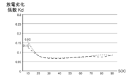
- FIGS. 3A and 3B are diagrams showing an example of a charge/discharge deterioration characteristic map.
- FIG. 3A shows an example of a charge deterioration characteristic map
- FIG. 3B shows an example of a discharge deterioration characteristic map.
- the horizontal axis indicates the usage range of SOC [%].
- each SOC value indicates the lower limit of the 10% usage range. For example, SOC 10% indicates that the battery is charged and discharged within the SOC range of 10 to 20%, and SOC 11% indicates that the battery is charged and discharged within the SOC range of 11 to 21%.
- the vertical axis indicates charge/discharge deterioration coefficients Kc and Kd.
- charge/discharge deterioration progresses approximately linearly with respect to the value obtained by multiplying the total charge amount or the total discharge amount (Ah) by the 0.5 power law (square root). Note that depending on the type of secondary battery, the rate may progress approximately linearly with respect to a value obtained by 0.4th power or 0.6th power of the total charge amount or total discharge amount (Ah).
- FIGS. 3A and 3B only depict charge/discharge deterioration characteristics for two types of current rates, 0.1C and 0.8C, but in reality, charge/discharge deterioration characteristics for many current rates are depicted. generated.
- the charging/discharging deterioration rate increases in the low and high SOC usage ranges, as shown in FIG. 3A.
- the charging/discharging deterioration rate increases in a region where the SOC usage range is low.
- the charge/discharge deterioration characteristics are also influenced by temperature, although it does not contribute as much as the current rate. Therefore, in order to improve the estimation accuracy of the charge/discharge deterioration rate, the charge/discharge deterioration characteristics that define the relationship between the SOC usage range and the charge/discharge deterioration coefficient are calculated for each two-dimensional combination of multiple current rates and multiple temperatures. It is preferable to prepare. On the other hand, when generating a simple charge/discharge deterioration characteristic map, it is sufficient to assume that the temperature is room temperature and prepare charge/discharge deterioration characteristics for each of a plurality of current rates.
- charge/discharge deterioration characteristics are defined not by a map but by a charge/discharge deterioration characteristic model (function) that uses the SOC usage range, current rate, and temperature as explanatory variables, and uses the charge/discharge deterioration coefficients Kc and Kd as objective variables. may be done.
- the temperature may be a constant.
- the storage deterioration characteristics, charge deterioration characteristics, and discharge deterioration characteristics of the secondary battery explained above are prepared for each of the positive electrode and the negative electrode.
- the storage deterioration characteristics, charge deterioration characteristics, and discharge deterioration characteristics of the secondary battery are used in switching processing of deterioration suppression control, which will be described later, and are not used in deterioration estimation processing of the secondary battery.
- the deterioration status of the positive electrode and negative electrode is independently analyzed by analyzing peak information appearing in the dV/dQ curve obtained by differentiating the charge/discharge curve of the secondary battery.
- the charge/discharge curve of a secondary battery is a curve that defines the relationship between charge/discharge amount and battery voltage.
- FIG. 4 is a diagram showing an example of a charge/discharge curve and a dV/dQ curve of a secondary battery, a positive electrode, and a negative electrode.
- the figure above shows the charge-discharge curve.
- the horizontal axis shows the capacity [Ah]
- the left vertical axis shows the battery voltage [V]
- the right vertical axis shows the negative electrode potential [VvsL + /L].
- the positive electrode potential [VvsL + /L] and the negative electrode potential [VvsL + /L] are potentials when the lithium potential is set to 0V.
- Battery voltage is the difference between the positive electrode potential and the negative electrode potential, and is defined by OCV.
- the figure below shows dV/dQ curves obtained by differentiating the charge/discharge curves of the secondary battery, positive electrode, and negative electrode, respectively.
- the horizontal axis shows capacitance [Ah]
- the vertical axis shows dV/dQ [V/Ah].
- lithium ions shuttle between the positive electrode active material and the negative electrode active material during charging and discharging.
- the negative electrode potential increases and the positive electrode potential decreases.
- the battery voltage will drop.
- the positive electrode potential increases and the negative electrode potential decreases. Battery voltage increases.
- the shape of the charge/discharge curve of a secondary battery differs depending on the type and amount of the positive electrode active material and negative electrode active material.
- the charge-discharge curve of a secondary battery has a shape in which the voltage gradually decreases, as shown in Figure 4, and structural changes originating from the positive electrode active material and the negative electrode active material can be extracted from the charge-discharge curve of the secondary battery. That is difficult.
- multiple peaks are observed in the dV/dQ curve of the secondary battery. Whether each peak originates from the structure of the positive electrode active material or the structure of the negative electrode active material can be determined from the shapes of the dV/dQ curve of the positive electrode and the dV/dQ curve of the negative electrode in at least the initial state. It can be estimated.
- Each peak corresponds to the maximum or minimum value of the rate of change of the positive electrode potential or negative electrode potential.
- the positive electrode potential and negative electrode potential are determined by the lithium composition ratio in the active material.
- the lithium composition ratio in the active material when the rate of change in potential becomes maximum or minimum is constant regardless of battery capacity. Therefore, the rate of decrease in the distance between the two peaks originating from the positive electrode of the dV/dQ curve of the secondary battery corresponds to the rate of decrease in the positive electrode capacity.
- the positive electrode It can be estimated that the capacity has decreased to 80% of the initial state. The same applies to the negative electrode.
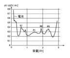
- FIG. 5 shows another example of the dV/dQ curve of a secondary battery.
- four peaks are extracted from the dV/dQ curve of the secondary battery.
- the first peak N1 and the third peak N2 are peaks originating from the negative electrode
- the second peak P1 and the fourth peak P2 are peaks originating from the positive electrode.
- the rate of decrease in the negative electrode capacity can be estimated from the rate of decrease in the distance between the first peak N1 and the third peak N2 (that is, the amount of charge required to transition from the first peak N1 to the third peak N2).
- the rate of decrease in the positive electrode capacity can be estimated from the rate of decrease in the distance between the second peak P1 and the fourth peak P2.
- the positive electrode potential and negative electrode potential can be detected by introducing a metallic lithium reference electrode into the secondary battery.
- the rate of decrease in the distance between the two peaks of the dV/dQ curve of the positive electrode can be directly determined.
- the rate of decrease in the distance between the two peaks of the dV/dQ curve of the negative electrode can be directly determined.
- the peak originating from the positive electrode and the peak originating from the negative electrode are identified among the multiple peaks of the dV/dQ curve of the secondary battery, and the reduction rate of the positive electrode capacity and the negative electrode capacity are Find the rate of decrease.
- the designer fills the positive electrode with more positive electrode active material than the positive electrode active material used for actual charging and discharging, and fills the negative electrode with more negative electrode active material than the negative electrode active material used for actual charging and discharging.
- the width of the charge/discharge curve of the positive electrode becomes wider, and as the amount of the negative electrode active material increases, the width of the charge/discharge curve of the negative electrode becomes wider.
- the width of the charge/discharge curves of the positive and negative electrodes shrinks due to deterioration.
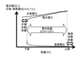
- FIG. 6 is a diagram showing an example of charge/discharge curves of a secondary battery, a positive electrode, and a negative electrode in an initial state of a certain secondary battery.
- the horizontal axis indicates capacity [Ah]
- the vertical axis indicates battery voltage [V], positive electrode potential [VvsL + /L], and negative electrode potential [VvsL + /L].
- the difference between the lower limit capacity of the positive electrode and the lower limit capacity of the battery is the positive electrode surplus capacity.
- the difference between the upper limit capacity of the negative electrode and the upper limit capacity of the battery is the negative electrode surplus capacity.
- FIG. 7 is a diagram showing an example of contraction of the charge/discharge curves of a secondary battery, a positive electrode, and a negative electrode.
- the upper figure shows a state in which the width of the charge/discharge curve of the positive electrode has shrunk by 10% due to deterioration of the positive electrode.
- the figure below shows a state in which the width of the charge/discharge curve of the negative electrode has shrunk by 10% due to deterioration of the negative electrode.
- the BMU of the secondary battery sets the range of the lower limit voltage and upper limit voltage of the secondary battery to the battery capacity.
- FIG. 8 is a flowchart showing the flow of the charging/discharging control method switching process by the deterioration suppression control system 10 according to the embodiment.
- the charge/discharge control unit 113 transmits a maintenance charging instruction to the control unit 32 of the charging station 30.
- maintenance charging may be performed once every several months.
- the power supply unit 31 charges the secondary battery 21 with a constant current at a current rate specified by the deterioration suppression control system 10.
- the control unit 25 of the electric vehicle 20 transmits battery data including voltage, current, temperature, and SOC during maintenance charging to the control unit 32 of the charging station 30.
- the control unit 32 of the charging station 30 transmits the battery data at the time of maintenance charging to the deterioration suppression control system 10.
- the data acquisition unit 111 of the deterioration suppression control system 10 acquires battery data during maintenance charging from the charging stand 30 and stores it in the battery data storage unit 121.
- the deterioration estimating unit 112 statistically processes battery data of a plurality of cells included in the secondary battery 21 during maintenance charging to generate battery data of a representative cell.
- the deterioration estimating unit 112 calculates the rate of decrease in battery capacity during the current maintenance charging with respect to the battery capacity during the previous maintenance charging, and compares the rate of decrease with a threshold value (S12). If the reduction rate is less than or equal to the threshold (N in S12), the process ends without switching the charging/discharging control method.
- the deterioration estimation unit 112 differentiates the charge/discharge curve of the representative cell to generate a dV/dQ curve of the representative cell.
- the deterioration estimating unit 112 estimates the rate of decrease in the current positive electrode surplus capacity with respect to the initial positive electrode surplus capacity based on the decrease rate in the distance between two peaks originating from the positive electrode of the dV/dQ curve.
- the reduction rate of positive electrode surplus capacity is defined as positive electrode relative deterioration degree [%] as shown in (Equation 1) below (S13).
- Positive electrode relative deterioration degree [%] 100 - (current positive electrode capacity - current battery capacity) / (initial positive electrode capacity - initial battery capacity) (Formula 1).
- the deterioration estimation unit 112 estimates the rate of decrease in the current negative electrode surplus capacity with respect to the initial negative electrode surplus capacity based on the decrease rate in the distance between two peaks originating from the negative electrode of the dV/dQ curve.
- the reduction rate of the negative electrode surplus capacity is defined as the negative electrode relative deterioration degree [%] as shown in the following (Equation 2) (S14).
- Negative electrode relative deterioration degree [%] 100 - (current negative electrode capacity - current battery capacity) / (initial negative electrode capacity - initial battery capacity) (Formula 2).
- the charge/discharge control unit 113 switches to charge/discharge control that prioritizes positive electrode deterioration suppression (S16), and the negative electrode relative deterioration degree is changed to the positive electrode relative deterioration degree. If it is larger (N in S15), the charge/discharge control is switched to one that gives priority to suppressing deterioration of the negative electrode (S17).
- the case where the relative deterioration degree of the negative electrode is larger than the relative deterioration degree of the positive electrode corresponds to the example shown in the lower diagram of FIG. Select discharge control.
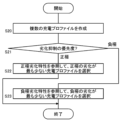
- FIG. 9 is a flowchart illustrating an example of deterioration suppression control during charging by the deterioration suppression control system 10 according to the embodiment.
- the charge/discharge control unit 113 generates a plurality of charging profiles before charging the secondary battery 21 (S20).
- the charge/discharge control unit 113 acquires the target SOC, charge start time, and charge end time of the secondary battery 21 based on the user's operation, and acquires the current SOC of the secondary battery 21 from the control unit 25 of the electric vehicle 20. do.
- the charging/discharging control unit 113 sets a plurality of slots at a predetermined step size within the chargeable time between the acquired charging start time and charging end time.
- the charge/discharge control unit 113 generates a plurality of patterns of charging profiles in which current rates are assigned to each slot within a range that satisfies the condition that the SOC of the secondary battery 21 reaches the target SOC at the charging end time.
- the current rate assigned to one slot may be 0 (dormant period).
- the charge/discharge control unit 113 may comprehensively generate several hundred patterns of charge profiles.
- the charge/discharge control unit 113 When charge/discharge control that prioritizes suppression of positive electrode deterioration is selected (positive electrode in S21), the charge/discharge control unit 113 refers to the storage deterioration characteristics and charge deterioration characteristics of the positive electrode from among the plurality of charging profiles.
- the charging profile that causes the least deterioration of the positive electrode is selected (S22). Specifically, the charge/discharge control unit 113 inputs the current rate and SOC of each slot of the charging profile, and calculates the positive electrode storage deterioration coefficient and the positive electrode charge deterioration coefficient of each slot.
- the charge/discharge control unit 113 selects the charging profile with the smallest total of the storage deterioration coefficient of the positive electrode and the charge deterioration coefficient of the positive electrode.
- the charge/discharge control unit 113 When charge/discharge control that prioritizes suppression of deterioration of the negative electrode is selected (negative electrode in S21), the charge/discharge control unit 113 refers to the storage deterioration characteristics and the charge deterioration characteristics of the negative electrode among the plurality of charging profiles.
- the charging profile that causes the least deterioration of the negative electrode is selected (S23). Specifically, the charge/discharge control unit 113 inputs the current rate and SOC of each slot of the charging profile, and calculates the negative electrode storage deterioration coefficient and the negative electrode charge deterioration coefficient of each slot.
- the charge/discharge control unit 113 selects the charging profile with the smallest sum of the storage deterioration coefficient of the negative electrode and the charge deterioration coefficient of the negative electrode.
- the charge/discharge control unit 113 when the electric vehicle 20 is a self-driving vehicle, a discharge plan in which deterioration is suppressed can be generated based on the delivery plan.
- the charge/discharge control unit 113 generates a plurality of discharge profiles before the electric vehicle 20 departs.
- the charge/discharge control unit 113 refers to the storage deterioration characteristics and charging deterioration characteristics of the positive electrode among the plurality of discharge profiles, and selects the one that causes the most deterioration of the positive electrode. Select less discharge profile.
- the charge/discharge control unit 113 refers to the storage deterioration characteristics and charge deterioration characteristics of the negative electrode among the plurality of discharge profiles, and selects the one that causes the most deterioration of the negative electrode. Select less discharge profile.
- the relative deterioration degree of the positive electrode and the negative electrode are determined based on the change in the peak position of the dV/dQ curve where the structural change of the positive electrode active material and the negative electrode active material appears and the change in battery capacity. Calculate the relative degree of deterioration of Using the relative deterioration degree of the positive electrode and the negative electrode as a measure, the relative deterioration degree of the positive electrode and the relative deterioration degree of the negative electrode are maintained in balance, that is, the charge-discharge curve of the positive electrode and the charge-discharge curve of the negative electrode overlap. Charge/discharge is controlled to maximize the area. Thereby, progression of cell level deterioration (decrease in SOH (State of Health)) can be suppressed to the maximum extent.
- the deterioration suppression control system 10 described above may be implemented in the control unit 25 of the electric vehicle 20 or the control unit 32 of the charging station 30.
- a four-wheeled electric vehicle is assumed as the electric vehicle 20.
- the electric vehicle 20 may be an electric motorcycle (electric scooter), an electric bicycle, or an electric kick scooter.
- electric vehicles include not only full electric vehicles but also low-speed electric vehicles such as golf carts and land cars.
- the object on which the secondary battery 21 is mounted is not limited to the electric vehicle 20. Objects to which the secondary battery 21 is installed include electric ships, railway vehicles, electric vehicles such as multicopters (drones), stationary power storage systems, and consumer electronic devices (smartphones, notebook PCs, etc.).
- an acquisition unit (111) that acquires battery data including voltage and current of the secondary battery (21); Based on the battery data of the secondary battery (21), calculate the rate of decrease in the current surplus capacity of the positive electrode relative to the initial surplus capacity of the positive electrode, and the rate of decrease in the current surplus capacity of the negative electrode relative to the initial surplus capacity of the negative electrode.
- an estimation unit (112) that estimates; If the rate of decrease in the surplus capacity of the positive electrode is greater than the rate of decrease in the surplus capacity of the negative electrode, the charge/discharge control is switched to a mode that prioritizes suppression of deterioration of the positive electrode, and the rate of decrease in the surplus capacity of the negative electrode is greater than the rate of decrease in the surplus capacity of the negative electrode.
- a charge/discharge control unit (113) that switches to charge/discharge control that prioritizes suppression of deterioration of the negative electrode when the rate is greater than the reduction rate;
- a deterioration suppression control system (10) comprising:
- the estimation unit (112) Differentiating a charge/discharge curve that defines the relationship between capacity and voltage of the secondary battery (21) to generate a dV/dQ curve; Estimating the rate of decrease in the surplus capacity of the positive electrode based on the rate of decrease in the distance between two peaks originating from the positive electrode of the dV / dQ curve, The deterioration suppression control system according to item 1 (10 ).
- the rate of decrease in the surplus capacity of the positive electrode and the rate of decrease in the surplus capacity of the negative electrode can be estimated with high accuracy.
- the switching frequency of charge/discharge control can be optimized.
- a deterioration characteristic holding unit (122) that holds storage deterioration characteristics, charging deterioration characteristics, storage deterioration characteristics and charging deterioration characteristics of the positive electrode, and storage deterioration characteristics and charging deterioration characteristics of the negative electrode of the secondary battery (21),
- the charge/discharge control unit (113) When charging and discharging control that prioritizes suppression of deterioration of the positive electrode is selected, a charging profile that causes the least deterioration of the positive electrode is selected by referring to storage deterioration characteristics and charging deterioration characteristics of the positive electrode among multiple charging profile candidates.
- a charging profile that causes the least deterioration of the negative electrode is selected by referring to the storage deterioration characteristics and charge deterioration characteristics of the negative electrode among the plurality of charging profile candidates.
- [Item 5] acquiring battery data including voltage and current of the secondary battery (21); Based on the battery data of the secondary battery (21), calculate the rate of decrease in the current surplus capacity of the positive electrode relative to the initial surplus capacity of the positive electrode, and the rate of decrease in the current surplus capacity of the negative electrode relative to the initial surplus capacity of the negative electrode. a step of estimating; If the rate of decrease in the surplus capacity of the positive electrode is greater than the rate of decrease in the surplus capacity of the negative electrode, the charge/discharge control is switched to a mode that prioritizes suppression of deterioration of the positive electrode, and the rate of decrease in the surplus capacity of the negative electrode is greater than the rate of decrease in the surplus capacity of the negative electrode. If it is larger than the reduction rate, switching to charge/discharge control that prioritizes suppression of deterioration of the negative electrode; A deterioration suppression control method characterized by having the following.
Landscapes
- Engineering & Computer Science (AREA)
- Power Engineering (AREA)
- Electrochemistry (AREA)
- Manufacturing & Machinery (AREA)
- Chemical & Material Sciences (AREA)
- Chemical Kinetics & Catalysis (AREA)
- General Chemical & Material Sciences (AREA)
- Microelectronics & Electronic Packaging (AREA)
- Secondary Cells (AREA)
- Charge And Discharge Circuits For Batteries Or The Like (AREA)
- Health & Medical Sciences (AREA)
- General Health & Medical Sciences (AREA)
- Medical Informatics (AREA)
Abstract
Description
二次電池(21)の電圧と電流を含む電池データを取得する取得部(111)と、
前記二次電池(21)の電池データをもとに、初期の正極の余剰容量に対する現在の正極の余剰容量の減少率と、初期の負極の余剰容量に対する現在の負極の余剰容量の減少率を推定する推定部(112)と、
前記正極の余剰容量の減少率が前記負極の余剰容量の減少率より大きい場合、前記正極の劣化抑制を優先した充放電制御に切り替え、前記負極の余剰容量の減少率が前記正極の余剰容量の減少率より大きい場合、前記負極の劣化抑制を優先した充放電制御に切り替える充放電制御部(113)と、
を備えることを特徴とする劣化抑制制御システム(10)。
前記推定部(112)は、
前記二次電池(21)の容量と電圧の関係を規定した充放電曲線を微分して、dV/dQ曲線を生成し、
前記dV/dQ曲線の正極に由来する2つのピーク間の距離の減少率をもとに前記正極の余剰容量の減少率を推定し、
前記dV/dQ曲線の負極に由来する2つのピーク間の距離の減少率をもとに前記負極の余剰容量の減少率を推定することを特徴とする項目1に記載の劣化抑制制御システム(10)。
前記二次電池(21)の容量の減少率が閾値を超えたとき、
前記推定部(112)は、前記正極の余剰容量の減少率と前記負極の余剰容量の減少率を推定し、
前記充放電制御部(113)は、両者の関係をもとに前記充放電制御の切り替え制御を実行する項目1に記載の劣化抑制制御システム(10)。
前記二次電池(21)の正極の保存劣化特性、充電劣化特性、負極の保存劣化特性、充電劣化特性を保持する劣化特性保持部(122)をさらに備え、
前記充放電制御部(113)は、前記二次電池(21)を充電する場合において、
前記正極の劣化抑制を優先した充放電制御を選択している場合、複数の充電プロファイル候補の内、前記正極の保存劣化特性と充電劣化特性を参照して、最も前記正極の劣化が少ない充電プロファイルを選択し、
前記負極の劣化抑制を優先した充放電制御を選択している場合、複数の充電プロファイル候補の内、前記負極の保存劣化特性と充電劣化特性を参照して、最も前記負極の劣化が少ない充電プロファイルを選択する項目1に記載の劣化抑制制御システム(10)。
二次電池(21)の電圧と電流を含む電池データを取得するステップと、
前記二次電池(21)の電池データをもとに、初期の正極の余剰容量に対する現在の正極の余剰容量の減少率と、初期の負極の余剰容量に対する現在の負極の余剰容量の減少率を推定するステップと、
前記正極の余剰容量の減少率が前記負極の余剰容量の減少率より大きい場合、前記正極の劣化抑制を優先した充放電制御に切り替え、前記負極の余剰容量の減少率が前記正極の余剰容量の減少率より大きい場合、前記負極の劣化抑制を優先した充放電制御に切り替えるステップと、
を有することを特徴とする劣化抑制制御方法。
二次電池(21)の電圧と電流を含む電池データを取得する処理と、
前記二次電池(21)の電池データをもとに、初期の正極の余剰容量に対する現在の正極の余剰容量の減少率と、初期の負極の余剰容量に対する現在の負極の余剰容量の減少率を推定する処理と、
前記正極の余剰容量の減少率が前記負極の余剰容量の減少率より大きい場合、前記正極の劣化抑制を優先した充放電制御に切り替え、前記負極の余剰容量の減少率が前記正極の余剰容量の減少率より大きい場合、前記負極の劣化抑制を優先した充放電制御に切り替える処理と、
をコンピュータに実行させることを特徴とする劣化抑制制御プログラム。
Claims (7)
- 二次電池の電圧と電流を含む電池データを取得する取得部と、
前記二次電池の電池データをもとに、初期の正極の余剰容量に対する現在の正極の余剰容量の減少率と、初期の負極の余剰容量に対する現在の負極の余剰容量の減少率を推定する推定部と、
前記正極の余剰容量の減少率が前記負極の余剰容量の減少率より大きい場合、前記正極の劣化抑制を優先した充放電制御に切り替え、前記負極の余剰容量の減少率が前記正極の余剰容量の減少率より大きい場合、前記負極の劣化抑制を優先した充放電制御に切り替える充放電制御部と、
を備えることを特徴とする劣化抑制制御システム。 - 前記推定部は、
前記二次電池の容量と電圧の関係を規定した充放電曲線を微分して、dV/dQ曲線を生成し、
前記dV/dQ曲線の正極に由来する2つのピーク間の距離の減少率をもとに前記正極の余剰容量の減少率を推定し、
前記dV/dQ曲線の負極に由来する2つのピーク間の距離の減少率をもとに前記負極の余剰容量の減少率を推定することを特徴とする請求項1に記載の劣化抑制制御システム。 - 前記二次電池の容量の減少率が閾値を超えたとき、
前記推定部は、前記正極の余剰容量の減少率と前記負極の余剰容量の減少率を推定し、
前記充放電制御部は、両者の関係をもとに前記充放電制御の切り替え制御を実行する請求項1に記載の劣化抑制制御システム。 - 前記二次電池の正極の保存劣化特性、充電劣化特性、負極の保存劣化特性、充電劣化特性を保持する劣化特性保持部をさらに備え、
前記充放電制御部は、前記二次電池を充電する場合において、
前記正極の劣化抑制を優先した充放電制御を選択している場合、複数の充電プロファイル候補の内、前記正極の保存劣化特性と充電劣化特性を参照して、最も前記正極の劣化が少ない充電プロファイルを選択し、
前記負極の劣化抑制を優先した充放電制御を選択している場合、複数の充電プロファイル候補の内、前記負極の保存劣化特性と充電劣化特性を参照して、最も前記負極の劣化が少ない充電プロファイルを選択する請求項1に記載の劣化抑制制御システム。 - 二次電池の電圧と電流を含む電池データを取得するステップと、
前記二次電池の電池データをもとに、初期の正極の余剰容量に対する現在の正極の余剰容量の減少率と、初期の負極の余剰容量に対する現在の負極の余剰容量の減少率を推定するステップと、
前記正極の余剰容量の減少率が前記負極の余剰容量の減少率より大きい場合、前記正極の劣化抑制を優先した充放電制御に切り替え、前記負極の余剰容量の減少率が前記正極の余剰容量の減少率より大きい場合、前記負極の劣化抑制を優先した充放電制御に切り替えるステップと、
を有することを特徴とする劣化抑制制御方法。 - 二次電池の電圧と電流を含む電池データを取得する処理と、
前記二次電池の電池データをもとに、初期の正極の余剰容量に対する現在の正極の余剰容量の減少率と、初期の負極の余剰容量に対する現在の負極の余剰容量の減少率を推定する処理と、
前記正極の余剰容量の減少率が前記負極の余剰容量の減少率より大きい場合、前記正極の劣化抑制を優先した充放電制御に切り替え、前記負極の余剰容量の減少率が前記正極の余剰容量の減少率より大きい場合、前記負極の劣化抑制を優先した充放電制御に切り替える処理と、
をコンピュータに実行させることを特徴とする劣化抑制制御プログラム。 - 請求項6の充電制御プログラムが記載された非一時的な記録媒体。
Priority Applications (4)
| Application Number | Priority Date | Filing Date | Title |
|---|---|---|---|
| US19/105,828 US20260058486A1 (en) | 2022-09-05 | 2023-08-22 | Deterioration inhibition control system, deterioration inhibition control method and deterioration inhibition control program, and recording medium having deterioration inhibition control program described thereon |
| JP2024545550A JPWO2024053392A1 (ja) | 2022-09-05 | 2023-08-22 | |
| CN202380059799.9A CN119731901A (zh) | 2022-09-05 | 2023-08-22 | 劣化抑制控制系统、劣化抑制控制方法、劣化抑制控制程序以及记载有劣化抑制控制程序的记录介质 |
| EP23862931.5A EP4586447A4 (en) | 2022-09-05 | 2023-08-22 | DETERIORATION INHIBITION CONTROL SYSTEM, DETERIORATION INHIBITION CONTROL METHOD AND DETERIORATION INHIBITION CONTROL PROGRAM, AND RECORDING MEDIUM HAVING A DETERIORATION INHIBITION CONTROL PROGRAM DESCRIBED THEREIN |
Applications Claiming Priority (2)
| Application Number | Priority Date | Filing Date | Title |
|---|---|---|---|
| JP2022-140794 | 2022-09-05 | ||
| JP2022140794 | 2022-09-05 |
Publications (1)
| Publication Number | Publication Date |
|---|---|
| WO2024053392A1 true WO2024053392A1 (ja) | 2024-03-14 |
Family
ID=90191114
Family Applications (1)
| Application Number | Title | Priority Date | Filing Date |
|---|---|---|---|
| PCT/JP2023/030174 Ceased WO2024053392A1 (ja) | 2022-09-05 | 2023-08-22 | 劣化抑制制御システム、劣化抑制制御方法および劣化抑制制御プログラム、劣化抑制制御プログラムが記載された記録媒体 |
Country Status (5)
| Country | Link |
|---|---|
| US (1) | US20260058486A1 (ja) |
| EP (1) | EP4586447A4 (ja) |
| JP (1) | JPWO2024053392A1 (ja) |
| CN (1) | CN119731901A (ja) |
| WO (1) | WO2024053392A1 (ja) |
Cited By (2)
| Publication number | Priority date | Publication date | Assignee | Title |
|---|---|---|---|---|
| CN118091529A (zh) * | 2024-04-28 | 2024-05-28 | 南方电网科学研究院有限责任公司 | 一种基于系统自补偿的直流充电桩现场监测装置及方法 |
| EP4693807A1 (en) * | 2024-08-08 | 2026-02-11 | Samsung Sdi Co., Ltd. | Apparatus and method for generating open circuit voltage profile |
Citations (4)
| Publication number | Priority date | Publication date | Assignee | Title |
|---|---|---|---|---|
| JP2010249797A (ja) * | 2009-03-26 | 2010-11-04 | Primearth Ev Energy Co Ltd | 二次電池の状態判定装置及び制御装置 |
| JP2017054692A (ja) | 2015-09-09 | 2017-03-16 | 株式会社日立製作所 | 蓄電システム、二次電池の制御システム及び二次電池の制御方法 |
| JP2018147827A (ja) * | 2017-03-08 | 2018-09-20 | 株式会社東芝 | 充放電制御装置、使用条件作成装置、プログラム、及び蓄電システム |
| WO2022014280A1 (ja) * | 2020-07-17 | 2022-01-20 | パナソニックIpマネジメント株式会社 | 情報処理方法及び充電制御装置 |
Family Cites Families (2)
| Publication number | Priority date | Publication date | Assignee | Title |
|---|---|---|---|---|
| JP6118906B2 (ja) * | 2013-08-22 | 2017-04-19 | 株式会社日立製作所 | リチウムイオン電池の充放電制御方法および充放電制御装置 |
| KR102865368B1 (ko) * | 2019-12-11 | 2025-09-25 | 주식회사 엘지에너지솔루션 | 전극의 상대적 퇴화도를 이용한 이차 전지의 동작 제어 장치 및 방법 |
-
2023
- 2023-08-22 EP EP23862931.5A patent/EP4586447A4/en active Pending
- 2023-08-22 WO PCT/JP2023/030174 patent/WO2024053392A1/ja not_active Ceased
- 2023-08-22 JP JP2024545550A patent/JPWO2024053392A1/ja active Pending
- 2023-08-22 CN CN202380059799.9A patent/CN119731901A/zh active Pending
- 2023-08-22 US US19/105,828 patent/US20260058486A1/en active Pending
Patent Citations (4)
| Publication number | Priority date | Publication date | Assignee | Title |
|---|---|---|---|---|
| JP2010249797A (ja) * | 2009-03-26 | 2010-11-04 | Primearth Ev Energy Co Ltd | 二次電池の状態判定装置及び制御装置 |
| JP2017054692A (ja) | 2015-09-09 | 2017-03-16 | 株式会社日立製作所 | 蓄電システム、二次電池の制御システム及び二次電池の制御方法 |
| JP2018147827A (ja) * | 2017-03-08 | 2018-09-20 | 株式会社東芝 | 充放電制御装置、使用条件作成装置、プログラム、及び蓄電システム |
| WO2022014280A1 (ja) * | 2020-07-17 | 2022-01-20 | パナソニックIpマネジメント株式会社 | 情報処理方法及び充電制御装置 |
Non-Patent Citations (1)
| Title |
|---|
| See also references of EP4586447A4 |
Cited By (3)
| Publication number | Priority date | Publication date | Assignee | Title |
|---|---|---|---|---|
| CN118091529A (zh) * | 2024-04-28 | 2024-05-28 | 南方电网科学研究院有限责任公司 | 一种基于系统自补偿的直流充电桩现场监测装置及方法 |
| CN118091529B (zh) * | 2024-04-28 | 2024-09-06 | 南方电网科学研究院有限责任公司 | 一种基于系统自补偿的直流充电桩现场监测装置及方法 |
| EP4693807A1 (en) * | 2024-08-08 | 2026-02-11 | Samsung Sdi Co., Ltd. | Apparatus and method for generating open circuit voltage profile |
Also Published As
| Publication number | Publication date |
|---|---|
| JPWO2024053392A1 (ja) | 2024-03-14 |
| EP4586447A4 (en) | 2025-12-24 |
| CN119731901A (zh) | 2025-03-28 |
| EP4586447A1 (en) | 2025-07-16 |
| US20260058486A1 (en) | 2026-02-26 |
Similar Documents
| Publication | Publication Date | Title |
|---|---|---|
| US11292360B2 (en) | Battery equalization method and system, vehicle, storage medium, and electronic device | |
| CN107576918B (zh) | 锂电池的剩余电量的估算方法及系统 | |
| WO2024053392A1 (ja) | 劣化抑制制御システム、劣化抑制制御方法および劣化抑制制御プログラム、劣化抑制制御プログラムが記載された記録媒体 | |
| CN107402355B (zh) | 一种充电时间预估方法 | |
| CN110031772B (zh) | 一种锂离子电池等效内阻的实时估算方法 | |
| CN113300016B (zh) | 一种电池充放电控制方法和装置 | |
| Hu et al. | Study on SOC estimation of lithium battery based on improved BP neural network | |
| CN119030099A (zh) | 储能系统soc均衡控制方法、装置、储能系统及存储介质 | |
| CN113900028B (zh) | 一种考虑初始荷电状态和充放电路径的电池健康状态估计方法及系统 | |
| CN115389939A (zh) | 基于最小二乘法的储能电池荷电和健康状态在线估计方法 | |
| JP6316754B2 (ja) | 電池管理装置および電源装置 | |
| CN116430262B (zh) | 储能电池的健康状态检测方法、装置和储能系统 | |
| WO2024084803A1 (ja) | データ補間システム、データ補間方法、及びデータ補間プログラム | |
| CN108446494B (zh) | 一种用于电池模组或系统的均衡算法 | |
| WO2024202580A1 (ja) | 電池分析システム、電池分析方法、電池分析プログラムおよび電池分析プログラムが記載された記憶媒体 | |
| KR20170028183A (ko) | 배터리의 잔존 에너지 추정 시스템 및 추정 방법 | |
| CN119151241A (zh) | 一种储能电池利用规划方法及系统 | |
| CN103698729A (zh) | 电池管理系统均衡能力的测定方法及设备 | |
| EP4632409A1 (en) | Battery analysis system, battery analysis method, battery analysis program, and storage medium containing battery analysis program | |
| CN114580253A (zh) | 一种电池管理系统更新包生成方法、云平台及系统 | |
| WO2026070114A1 (ja) | 電池分析システム、電池分析方法および電池分析プログラム | |
| EP4653899A1 (en) | Battery abnormality detection system, battery abnormality detection method, battery abnormality detection program, and recording medium having battery abnormality detection program recorded thereon | |
| Joshua et al. | Improved State-of-Charge and State-of-Health Algorithms for Battery Management Systems | |
| WO2026048525A1 (ja) | 電池分析システム、電池分析方法および電池分析プログラム | |
| CN120051698A (zh) | 数据插补系统、数据插补方法、以及数据插补程序产品 |
Legal Events
| Date | Code | Title | Description |
|---|---|---|---|
| 121 | Ep: the epo has been informed by wipo that ep was designated in this application |
Ref document number: 23862931 Country of ref document: EP Kind code of ref document: A1 |
|
| WWE | Wipo information: entry into national phase |
Ref document number: 2024545550 Country of ref document: JP |
|
| WWE | Wipo information: entry into national phase |
Ref document number: 202380059799.9 Country of ref document: CN |
|
| WWE | Wipo information: entry into national phase |
Ref document number: 202517026011 Country of ref document: IN |
|
| WWP | Wipo information: published in national office |
Ref document number: 202380059799.9 Country of ref document: CN |
|
| WWE | Wipo information: entry into national phase |
Ref document number: 2023862931 Country of ref document: EP |
|
| NENP | Non-entry into the national phase |
Ref country code: DE |
|
| WWP | Wipo information: published in national office |
Ref document number: 202517026011 Country of ref document: IN |
|
| ENP | Entry into the national phase |
Ref document number: 2023862931 Country of ref document: EP Effective date: 20250407 |
|
| WWP | Wipo information: published in national office |
Ref document number: 2023862931 Country of ref document: EP |