WO2024057406A1 - 移動焼入れ方法及び移動焼入れ装置 - Google Patents
移動焼入れ方法及び移動焼入れ装置 Download PDFInfo
- Publication number
- WO2024057406A1 WO2024057406A1 PCT/JP2022/034240 JP2022034240W WO2024057406A1 WO 2024057406 A1 WO2024057406 A1 WO 2024057406A1 JP 2022034240 W JP2022034240 W JP 2022034240W WO 2024057406 A1 WO2024057406 A1 WO 2024057406A1
- Authority
- WO
- WIPO (PCT)
- Prior art keywords
- frequency coil
- axial direction
- shaft
- cooling
- frequency
- Prior art date
- Legal status (The legal status is an assumption and is not a legal conclusion. Google has not performed a legal analysis and makes no representation as to the accuracy of the status listed.)
- Ceased
Links
Images


Classifications
-
- C—CHEMISTRY; METALLURGY
- C21—METALLURGY OF IRON
- C21D—MODIFYING THE PHYSICAL STRUCTURE OF FERROUS METALS; GENERAL DEVICES FOR HEAT TREATMENT OF FERROUS OR NON-FERROUS METALS OR ALLOYS; MAKING METAL MALLEABLE, e.g. BY DECARBURISATION OR TEMPERING
- C21D9/00—Heat treatment, e.g. annealing, hardening, quenching or tempering, adapted for particular articles; Furnaces therefor
- C21D9/28—Heat treatment, e.g. annealing, hardening, quenching or tempering, adapted for particular articles; Furnaces therefor for plain shafts
-
- C—CHEMISTRY; METALLURGY
- C21—METALLURGY OF IRON
- C21D—MODIFYING THE PHYSICAL STRUCTURE OF FERROUS METALS; GENERAL DEVICES FOR HEAT TREATMENT OF FERROUS OR NON-FERROUS METALS OR ALLOYS; MAKING METAL MALLEABLE, e.g. BY DECARBURISATION OR TEMPERING
- C21D1/00—General methods or devices for heat treatment, e.g. annealing, hardening, quenching or tempering
- C21D1/06—Surface hardening
- C21D1/09—Surface hardening by direct application of electrical or wave energy; by particle radiation
- C21D1/10—Surface hardening by direct application of electrical or wave energy; by particle radiation by electric induction
-
- C—CHEMISTRY; METALLURGY
- C21—METALLURGY OF IRON
- C21D—MODIFYING THE PHYSICAL STRUCTURE OF FERROUS METALS; GENERAL DEVICES FOR HEAT TREATMENT OF FERROUS OR NON-FERROUS METALS OR ALLOYS; MAKING METAL MALLEABLE, e.g. BY DECARBURISATION OR TEMPERING
- C21D1/00—General methods or devices for heat treatment, e.g. annealing, hardening, quenching or tempering
- C21D1/18—Hardening; Quenching with or without subsequent tempering
-
- C—CHEMISTRY; METALLURGY
- C21—METALLURGY OF IRON
- C21D—MODIFYING THE PHYSICAL STRUCTURE OF FERROUS METALS; GENERAL DEVICES FOR HEAT TREATMENT OF FERROUS OR NON-FERROUS METALS OR ALLOYS; MAKING METAL MALLEABLE, e.g. BY DECARBURISATION OR TEMPERING
- C21D1/00—General methods or devices for heat treatment, e.g. annealing, hardening, quenching or tempering
- C21D1/62—Quenching devices
- C21D1/667—Quenching devices for spray quenching
-
- C—CHEMISTRY; METALLURGY
- C21—METALLURGY OF IRON
- C21D—MODIFYING THE PHYSICAL STRUCTURE OF FERROUS METALS; GENERAL DEVICES FOR HEAT TREATMENT OF FERROUS OR NON-FERROUS METALS OR ALLOYS; MAKING METAL MALLEABLE, e.g. BY DECARBURISATION OR TEMPERING
- C21D11/00—Process control or regulation for heat treatments
-
- C—CHEMISTRY; METALLURGY
- C21—METALLURGY OF IRON
- C21D—MODIFYING THE PHYSICAL STRUCTURE OF FERROUS METALS; GENERAL DEVICES FOR HEAT TREATMENT OF FERROUS OR NON-FERROUS METALS OR ALLOYS; MAKING METAL MALLEABLE, e.g. BY DECARBURISATION OR TEMPERING
- C21D11/00—Process control or regulation for heat treatments
- C21D11/005—Process control or regulation for heat treatments for cooling
-
- C—CHEMISTRY; METALLURGY
- C21—METALLURGY OF IRON
- C21D—MODIFYING THE PHYSICAL STRUCTURE OF FERROUS METALS; GENERAL DEVICES FOR HEAT TREATMENT OF FERROUS OR NON-FERROUS METALS OR ALLOYS; MAKING METAL MALLEABLE, e.g. BY DECARBURISATION OR TEMPERING
- C21D9/00—Heat treatment, e.g. annealing, hardening, quenching or tempering, adapted for particular articles; Furnaces therefor
- C21D9/0062—Heat-treating apparatus with a cooling or quenching zone
-
- F—MECHANICAL ENGINEERING; LIGHTING; HEATING; WEAPONS; BLASTING
- F27—FURNACES; KILNS; OVENS; RETORTS
- F27D—DETAILS OR ACCESSORIES OF FURNACES, KILNS, OVENS OR RETORTS, IN SO FAR AS THEY ARE OF KINDS OCCURRING IN MORE THAN ONE KIND OF FURNACE
- F27D11/00—Arrangement of elements for electric heating in or on furnaces
- F27D11/06—Induction heating, i.e. in which the material being heated, or its container or elements embodied therein, form the secondary of a transformer
-
- H—ELECTRICITY
- H05—ELECTRIC TECHNIQUES NOT OTHERWISE PROVIDED FOR
- H05B—ELECTRIC HEATING; ELECTRIC LIGHT SOURCES NOT OTHERWISE PROVIDED FOR; CIRCUIT ARRANGEMENTS FOR ELECTRIC LIGHT SOURCES, IN GENERAL
- H05B6/00—Heating by electric, magnetic or electromagnetic fields
- H05B6/02—Induction heating
- H05B6/10—Induction heating apparatus, other than furnaces, for specific applications
- H05B6/101—Induction heating apparatus, other than furnaces, for specific applications for local heating of metal pieces
- H05B6/102—Induction heating apparatus, other than furnaces, for specific applications for local heating of metal pieces the metal pieces being rotated while induction heated
-
- H—ELECTRICITY
- H05—ELECTRIC TECHNIQUES NOT OTHERWISE PROVIDED FOR
- H05B—ELECTRIC HEATING; ELECTRIC LIGHT SOURCES NOT OTHERWISE PROVIDED FOR; CIRCUIT ARRANGEMENTS FOR ELECTRIC LIGHT SOURCES, IN GENERAL
- H05B6/00—Heating by electric, magnetic or electromagnetic fields
- H05B6/02—Induction heating
- H05B6/10—Induction heating apparatus, other than furnaces, for specific applications
- H05B6/101—Induction heating apparatus, other than furnaces, for specific applications for local heating of metal pieces
- H05B6/103—Induction heating apparatus, other than furnaces, for specific applications for local heating of metal pieces multiple metal pieces successively being moved close to the inductor
-
- H—ELECTRICITY
- H05—ELECTRIC TECHNIQUES NOT OTHERWISE PROVIDED FOR
- H05B—ELECTRIC HEATING; ELECTRIC LIGHT SOURCES NOT OTHERWISE PROVIDED FOR; CIRCUIT ARRANGEMENTS FOR ELECTRIC LIGHT SOURCES, IN GENERAL
- H05B6/00—Heating by electric, magnetic or electromagnetic fields
- H05B6/02—Induction heating
- H05B6/36—Coil arrangements
- H05B6/40—Establishing desired heat distribution, e.g. to heat particular parts of workpieces
-
- H—ELECTRICITY
- H05—ELECTRIC TECHNIQUES NOT OTHERWISE PROVIDED FOR
- H05B—ELECTRIC HEATING; ELECTRIC LIGHT SOURCES NOT OTHERWISE PROVIDED FOR; CIRCUIT ARRANGEMENTS FOR ELECTRIC LIGHT SOURCES, IN GENERAL
- H05B6/00—Heating by electric, magnetic or electromagnetic fields
- H05B6/02—Induction heating
- H05B6/36—Coil arrangements
- H05B6/44—Coil arrangements having more than one coil or coil segment
-
- C—CHEMISTRY; METALLURGY
- C21—METALLURGY OF IRON
- C21D—MODIFYING THE PHYSICAL STRUCTURE OF FERROUS METALS; GENERAL DEVICES FOR HEAT TREATMENT OF FERROUS OR NON-FERROUS METALS OR ALLOYS; MAKING METAL MALLEABLE, e.g. BY DECARBURISATION OR TEMPERING
- C21D1/00—General methods or devices for heat treatment, e.g. annealing, hardening, quenching or tempering
- C21D1/56—General methods or devices for heat treatment, e.g. annealing, hardening, quenching or tempering characterised by the quenching agents
- C21D1/58—Oils
-
- C—CHEMISTRY; METALLURGY
- C21—METALLURGY OF IRON
- C21D—MODIFYING THE PHYSICAL STRUCTURE OF FERROUS METALS; GENERAL DEVICES FOR HEAT TREATMENT OF FERROUS OR NON-FERROUS METALS OR ALLOYS; MAKING METAL MALLEABLE, e.g. BY DECARBURISATION OR TEMPERING
- C21D1/00—General methods or devices for heat treatment, e.g. annealing, hardening, quenching or tempering
- C21D1/56—General methods or devices for heat treatment, e.g. annealing, hardening, quenching or tempering characterised by the quenching agents
- C21D1/60—Aqueous agents
-
- C—CHEMISTRY; METALLURGY
- C21—METALLURGY OF IRON
- C21D—MODIFYING THE PHYSICAL STRUCTURE OF FERROUS METALS; GENERAL DEVICES FOR HEAT TREATMENT OF FERROUS OR NON-FERROUS METALS OR ALLOYS; MAKING METAL MALLEABLE, e.g. BY DECARBURISATION OR TEMPERING
- C21D2211/00—Microstructure comprising significant phases
- C21D2211/008—Martensite
-
- C—CHEMISTRY; METALLURGY
- C21—METALLURGY OF IRON
- C21D—MODIFYING THE PHYSICAL STRUCTURE OF FERROUS METALS; GENERAL DEVICES FOR HEAT TREATMENT OF FERROUS OR NON-FERROUS METALS OR ALLOYS; MAKING METAL MALLEABLE, e.g. BY DECARBURISATION OR TEMPERING
- C21D2221/00—Treating localised areas of an article
- C21D2221/10—Differential treatment of inner with respect to outer regions, e.g. core and periphery, respectively
-
- Y—GENERAL TAGGING OF NEW TECHNOLOGICAL DEVELOPMENTS; GENERAL TAGGING OF CROSS-SECTIONAL TECHNOLOGIES SPANNING OVER SEVERAL SECTIONS OF THE IPC; TECHNICAL SUBJECTS COVERED BY FORMER USPC CROSS-REFERENCE ART COLLECTIONS [XRACs] AND DIGESTS
- Y02—TECHNOLOGIES OR APPLICATIONS FOR MITIGATION OR ADAPTATION AGAINST CLIMATE CHANGE
- Y02P—CLIMATE CHANGE MITIGATION TECHNOLOGIES IN THE PRODUCTION OR PROCESSING OF GOODS
- Y02P10/00—Technologies related to metal processing
- Y02P10/25—Process efficiency
Definitions
- the present invention relates to a mobile hardening method and a mobile hardening apparatus.
- induction hardening is widely used to improve the surface hardness, wear resistance, and fatigue resistance of parts.
- various induction hardening devices have been proposed. For example, when induction hardening a long member such as a steel shaft, so-called displacement hardening is performed. Traverse hardening is a method of hardening while moving a high-frequency induction heating coil (also referred to as a high-frequency coil) and a cooling means relative to the shaft-like body along the axial direction of the shaft-like body. .
- a high-frequency induction heating coil also referred to as a high-frequency coil
- the shaft-like body In moving hardening, the shaft-like body is locally heated by a high-frequency coil until at least the surface layer of the shaft-like body becomes an austenite phase. Next, by using a cooling means that follows the high-frequency coil, a cooling medium such as a cooling liquid is injected onto the surface of the heated shaft-shaped body to rapidly cool it in a short period of time, thereby converting the surface layer of the shaft-shaped body into a desired phase such as a martensite phase.
- the structure has hardness.
- the outer diameter of the shaft-shaped body may not be constant in the direction along its axis (also referred to as the axial direction). That is, in the axial direction of the shaft-like body, there is a shaft-like body having a small diameter portion having a relatively small outer diameter and a large diameter portion having a relatively large outside diameter. Further, the small diameter portion and the large diameter portion are connected by a step portion whose outer diameter gradually changes in the axial direction. For example, in the technology disclosed in Patent Document 1 or Patent Document 2, by moving split coils back and forth in the radial direction of the shaft-like body that is the heated object, changes in the outer diameter of the shaft-like body are accommodated. .
- variable diameter coil method has the advantage of simplifying the equipment configuration, it is important to appropriately control the moving speed of the coil.
- the reason is as follows. In order to uniformly heat the stepped portion of the shaft-like body in the axial direction, it is desirable to keep the moving speed along the surface as constant as possible when trying to move the coil along the radial direction of the shaft cross section. If the speed of movement of the coil in the axial direction is constant instead of the speed of movement along the surface, heating will be concentrated at the corners of the step, and the heating in the recesses of the step will be conversely reduced.
- the present invention has been made in view of the above circumstances, and provides a mobile hardening method and a mobile hardening device that can perform desired hardening on the step portion and the vicinity thereof in a shaft-shaped body whose outer diameter is not constant in the axial direction.
- the purpose is to provide
- a moving hardening method uses a moving hardening device including a plurality of high-frequency coils and a cooling section to separate a small diameter part, a large diameter part, and a small diameter part and a large diameter part in the axial direction.
- a moving hardening method for hardening a shaft-like body having a stepped part connecting the diameter part The shaft-shaped body inserted inside the plurality of high-frequency coils is rotated relative to the plurality of high-frequency coils, and the plurality of high-frequency coils are rotated relative to the shaft-shaped body in the axial direction.
- the speed of the high frequency coil in the axial direction when the high frequency coil passes through the stepped portion is higher than the speed in the axial direction of the high frequency coil when the high frequency coil passes through the small diameter portion or the large diameter portion. It is also characterized by its small size.
- the speed of the high frequency coil in the axial direction when the high frequency coil passes through the small diameter portion or the large diameter portion is V0, and the high frequency coil is set at the stepped portion.
- the speed of the high-frequency coil in the axial direction when passing through is Vs
- the speed of the plurality of high-frequency coils in the direction perpendicular to the axial direction is Vc
- the following equation 1 may hold true.
- the distance between the high-frequency coil and the cooling section in the axial direction when the high-frequency coil passes through the stepped portion is determined by the high-frequency coil.
- the distance may be smaller than the distance between the high frequency coil and the cooling section in the axial direction when passing through the small diameter section or the large diameter section.
- the cooling unit injects a cooling medium,
- the injection amount or injection pressure of the cooling medium when the high-frequency coil passes through the stepped portion is determined from the injection amount or injection pressure of the cooling medium when the high-frequency coil passes through the small diameter portion or the large diameter portion. You can also make it smaller.
- a mobile hardening device hardens a shaft-shaped body having a small diameter portion, a large diameter portion, and a stepped portion connecting the small diameter portion and the large diameter portion in the axial direction.
- a mobile quenching device for The mobile quenching device is In the axial direction, a plurality of high frequency coils and a cooling section are provided, comprising a control unit capable of controlling movement of the plurality of high frequency coils and the cooling unit, Each of the high-frequency coils has a high-frequency induction part for heating the shaft-shaped body and a conductive part connected to the high-frequency induction part, and is movable in the axial direction with respect to the shaft-shaped body.
- the cooling unit has an injection unit capable of injecting a cooling medium, and is movable in the axial direction with respect to the shaft-like body
- the control unit includes: The movement of the high-frequency coils can be controlled in the plane so that the distance from the surface of the shaft-like body to each of the high-frequency coils is constant, and The speed of the high frequency coil in the axial direction when the high frequency coil passes through the stepped portion is higher than the speed in the axial direction of the high frequency coil when the high frequency coil passes through the small diameter portion or the large diameter portion. It is characterized in that it can be controlled so that it also becomes small.
- the control unit sets the speed of the high frequency coil in the axial direction when the high frequency coil passes through the small diameter portion or the large diameter portion to V0, and the high frequency
- the speed of the high-frequency coil in the axial direction when the coil passes through the stepped portion is Vs
- the speed of the plurality of high-frequency coils in the direction orthogonal to the axial direction is Vc
- the following formula 1 holds true.
- the high frequency coil may be controllable.
- the control unit may control a distance between the high-frequency coil and the cooling unit in the axial direction when the high-frequency coil passes through the stepped portion.
- the distance between the high frequency coil and the cooling section in the axial direction when the high frequency coil passes through the small diameter section or the large diameter section may be controlled to be smaller than the distance between the high frequency coil and the cooling section.
- the control unit controls the injection amount or injection pressure of the cooling medium when the high-frequency coil passes through the stepped portion.
- the cooling medium may be controlled to be smaller than an injection amount or an injection pressure of the cooling medium when the high-frequency coil passes through the small diameter portion or the large diameter portion.
- the moving hardening method and moving hardening apparatus of the present invention it is possible to perform desired hardening on the stepped portion and the vicinity thereof in the shaft-shaped body whose outer diameter is not constant in the axial direction.
- FIG. 1 is a side view schematically showing a partially cutaway view of a mobile hardening device according to an embodiment of the present invention. It is a sectional view schematically showing a partial cross section of the shaft-like body and two high-frequency coils when viewed from above in a direction along the axis of the shaft-like body, and the high-frequency coil moves according to the outer diameter of the small diameter part.
- FIG. FIG. 2 is a cross-sectional view schematically showing a partial cross section of the shaft-like body and two high-frequency coils when viewed from above in a direction along the axis of the shaft-like body, and the high-frequency coil is arranged in accordance with the outer diameter of the large diameter portion.
- FIG. 1 It is a figure which shows the state which moved. It is a sectional view schematically showing a partial cross section of the shaft-like body and three high-frequency coils when viewed from above in a direction along the axis of the shaft-like body, and the high-frequency coil moves according to the outer diameter of the small diameter part.
- FIG. It is a sectional view schematically showing a partial cross section of the shaft-like body and three high-frequency coils when viewed from above in a direction along the axis of the shaft-like body, and the high-frequency coil is arranged in accordance with the outer diameter of the large diameter portion. It is a figure which shows the state which moved.
- FIG. 3 is a schematic perspective view for explaining the positional relationship between a heating section and a cooling section with respect to a shaft-shaped body in an embodiment of the present invention.
- FIG. 2 is a schematic cross-sectional view of the shaft-like body and the high-frequency coil taken along a plane passing through the axis of the shaft-like body. It is a sectional view schematically showing a partial cross section of the shaft-like body and one high-frequency coil when viewed from above in a direction along the axis of the shaft-like body, and the high-frequency coil moves according to the outer diameter of the small diameter part.
- FIG. 2 is a schematic cross-sectional view of the shaft-like body and the high-frequency coil taken along a plane passing through the axis of the shaft-like body. It is a sectional view schematically showing a partial cross section of the shaft-like body and one high-frequency coil when viewed from above in a direction along the axis of the shaft-like body, and the high-frequency coil moves according to the
- FIGS. 1 to 10 a moving hardening method and a moving hardening apparatus that are embodiments of the present invention will be described with reference to FIGS. 1 to 10. Note that it is obvious that the present invention is not limited to the following embodiments. Furthermore, it is obvious that elements of the following embodiments can be combined within the scope of the present invention.
- a traverse hardening apparatus 100 of the present embodiment is an apparatus for performing traverse hardening on a shaft-shaped body 10 using a high-frequency current.
- Movement hardening is a method of hardening while moving a heating section equipped with a high-frequency induction heating coil (also referred to as a high-frequency coil) and a cooling section equipped with a cooling ring that follows the heating section relative to the object to be heated. It is.
- the object to be heated is, for example, a shaft-shaped object.
- the shaft-shaped body 10 has a large diameter portion 11 (a large diameter portion 11A and a large diameter portion 11B) and a small diameter portion 12 provided between the large diameter portion 11A and the large diameter portion 11B in the direction along the axis C.
- the large diameter portion 11A, the large diameter portion 11B, and the small diameter portion 12 are each formed in a columnar shape.
- the respective central axes of the large diameter portion 11A, the large diameter portion 11B, and the small diameter portion 12 are arranged to coincide with an axis C that is a common axis.
- the axis C is the central axis of the shaft-like body 10.
- the portion disposed on one side D1 of the small diameter portion 12 in the direction along the axis C will also be referred to as the first large diameter portion 11A.
- a portion disposed on the other side D2 of the small diameter portion 12 in the direction along the axis C is also referred to as a second large diameter portion 11B.
- the first large diameter portion 11A, the small diameter portion 12, and the second large diameter portion 11B are each formed in a cylindrical shape and share the axis C as a common central axis.
- the outer diameter of the small diameter portion 12 is smaller than the respective outer diameters of the large diameter portions 11A and 11B.
- the outer diameter of the large diameter portion 11A and the outer diameter of the large diameter portion 11B are the same, but the outer diameter of the large diameter portion 11A and the outer diameter of the large diameter portion 11B may be different.
- a stepped portion 13 (stepped portion 13A and stepped portion 13B) for connecting them.
- the stepped portion 13A and the stepped portion 13B are inclined at a predetermined angle with respect to the axis C of the shaft-like body 10.
- the angle of inclination is, for example, in the range of 15° to 90°.
- the outer diameter of the stepped portion 13 is not particularly limited, but it may have a shape that smoothly connects the large-diameter portion 11 and the small-diameter portion 12, as illustrated in FIG. You can.
- the shaft-shaped body 10 is arranged so that the axis C is parallel to the vertical direction of the mobile hardening apparatus 100.
- the shaft-like body 10 is made of a conductive material such as carbon steel or low alloy steel containing 95% by weight or more of iron (Fe), which is a ferrite phase or pearlite phase.
- the shaft-like body may be an axle for a railway vehicle or the like.
- the number of large-diameter portions 11, stepped portions 13, etc. included in the shaft-like body 10 is not limited to the example shown in FIG. 1.
- the number of small diameter portions 12, large diameter portions 11, and step portions 13 may be 1, 2, or 3, or may be 4 or more.
- the shaft-like body to which the mobile hardening method and mobile hardening apparatus of the present embodiment is applied may be a shaft-like body having one large diameter portion and one small diameter portion.
- the mobile hardening device 100 includes a heating section 110, a cooling section 120, a support section 130, a heating section moving device 140, a cooling section moving device 150, and a control section 160.
- the heating section 110 includes a plurality of high frequency coils 111 (high frequency coil 111A and high frequency coil 111B).
- the heating section 110 is connected to a heating section moving device 140 that is a moving means.
- the cooling unit 120 includes a cooling ring 121.
- the cooling unit 120 is connected to a cooling unit moving device 150 that is a moving means.
- the support portion 130 includes an upper center 131 and a lower center 132.
- the upper center 131 supports the first large diameter portion 11A of the shaft-like body 10 from above the first large diameter portion 11A.
- the lower center 132 supports the second large diameter portion 11B of the shaft-like body 10 from below the second large diameter portion 11B.
- the upper center 131 and the lower center 132 support the shaft-like body 10 so that one side D1 in the direction of the axis C is upward and the other side D2 is downward. Note that the shaft-like body 10 is rotatable in the circumferential direction of the shaft-like body 10 about the axis C while being supported by the upper center 131 and the lower center 132.
- the shaft-like body 10 can be rotated around the axis of the shaft-like body 10 during moving hardening by a drive device (not shown).
- Rotating the shaft-like body 10 around the axis means rotating the shaft-like body 10 in any of the circumferential directions around the axis C of the shaft-like body 10 .
- a line connecting the center of the upper center 131 and the center of the lower center 132 is the vertical direction (also referred to as the vertical direction) of the mobile hardening device 100.
- the heating unit moving device 140 supports the heating unit 110 and includes a support member 141 and a motor (not shown).
- the heating unit moving device 140 is attached to a rack member 180.
- Rack member 180 extends along the vertical direction.
- the support member 141 is provided with a pinion gear 141a, and the pinion gear 141a meshes with a gear portion 180a of the rack member 180.
- the motor is driven, the pinion gear 141a rotates, and the heating unit moving device 140 is configured to move upward or downward relative to the rack member 180.
- the cooling unit moving device 150 supports the cooling unit 120 and includes a support member 151 and a motor (not shown). Cooling unit moving device 150 is attached to rack member 180.
- the support member 151 is provided with a pinion gear 151a, and the pinion gear 151a meshes with a gear portion 180a of the rack member 180. When the motor is driven, the pinion gear 151a rotates, and the cooling unit moving device 150 is configured to move upward or downward relative to the rack member 180.
- the moving speeds of the heating section moving device 140 and the cooling section moving device 150 are each independently controlled by the control section 160.
- movement hardening is performed in the axial direction of the shaft-shaped body 10. That is, the vertical direction of the mobile hardening apparatus 100 can be said to be the direction in which mobile hardening is performed.
- FIG. 1 shows an example in which a rack and pinion gear are used as a mechanism for moving the heating section 110 and the cooling section 120 in the vertical direction
- the moving mechanism of the present invention is not limited to this. Any material may be used as long as it can move relative to the shaft-like body 10 in the vertical direction.
- FIG. 1 shows an example in which the heating section 110 and the cooling section 120 move relative to the fixed shaft-like body 10, the moving hardening method and moving hardening apparatus of the present invention are not limited to this form.
- the portion 110 and the cooling portion 120 may be fixed, and the shaft-like body 10 may be moved relative to the heating portion 110 and the cooling portion 120.
- FIG. 1 shows an example in which a rack and pinion gear are used as a mechanism for moving the heating section 110 and the cooling section 120 in the vertical direction
- the moving mechanism of the present invention is not limited to this. Any material may be used as long as it can move relative to the shaft-like body 10 in the vertical direction.
- FIG. 1 shows an example in which the heating section 110
- the moving hardening method and the mobile hardening apparatus of the present invention are not limited to this. It may be oriented horizontally, or the axial direction of the shaft-shaped body 10 may be inclined with respect to the vertical direction.
- the heating unit 110 of this embodiment includes a plurality of high frequency coils.
- FIG. 2 schematically shows the high-frequency coil 111A and high-frequency coil 111B included in the heating section 110 and the shaft-like body 10 as viewed from the AA direction (parallel to the axial direction) in FIG. 1 in the direction along the axis C. A top view is shown.
- the shaft-like body 10 is shown broken in the middle of the small diameter portion 12.
- the high-frequency coil 111A and the high-frequency coil 111B included in the heating unit 110 are such that a part thereof surrounds the shaft-like body 10 in a plan view when viewed from a direction along the axis C of the shaft-like body 10.
- the high frequency induction section 112A is connected to conductive sections 113a and 113b at its ends.
- the high frequency induction section 112B is connected to the conductive sections 113c and 113d at its ends.
- the high-frequency coil 111A and the high-frequency coil 111B are arranged side by side and spaced apart from each other in the circumferential direction (also referred to as the circumferential direction) centered on the axis C of the shaft-like body 10.
- This circumferential direction is parallel to the direction in which the high frequency induction section 112A of the high frequency coil 111A and the high frequency induction section 112B of the high frequency coil 111B extend. That is, the plane (also referred to as a horizontal plane) on which the high-frequency guide section 112A and the high-frequency guide section 112B extend is perpendicular to the vertical direction of the mobile hardening apparatus 100. Further, the horizontal plane is perpendicular to the axial direction of the shaft-like body 10.
- the shape of the high-frequency induction portion 112A of the high-frequency coil 111A and the high-frequency induction portion 112B of the high-frequency coil 111B may be an arc shape as shown in FIG. Since the high-frequency guide portions 112A and 112B have an arcuate shape, there is an advantage that the high-frequency coil 111 and the shaft-shaped body 10 are uniformly close to each other in the circumferential direction.
- the above-mentioned horizontal plane is in contact with each inner surface (the surface on the shaft-shaped body 10 side) of the high-frequency guide portion 112A and the high-frequency guide portion 112B facing the axis C.
- the diameter of the upper inscribed circle is preferably larger than the outer diameter of the small diameter portion 12 of the shaft-like body 10 and smaller than the outer diameter of the large diameter portion 11.
- the high-frequency guide section 112A and the high-frequency guide section 112B may form part of an elliptical shape in the horizontal plane, or may have a shape composed of a plurality of straight lines.
- the high-frequency coil 111A and the high-frequency coil 111B may have a shape such that a part of the high-frequency coil 111A and a part of the high-frequency coil 111B overlap when viewed in the axial direction of the shaft-shaped body 10.
- the conductive part 113a and the conductive part 113b in FIG. 2 may be located closer to the high-frequency induction part 112B than the conductive part 113d and the conductive part 113c, respectively.
- the high frequency coil 111A and the high frequency coil 111B are arranged at different positions in the axial direction.
- the conductive part 113a, the conductive part 113b, the conductive part 113c, and the conductive part 113d each extend in a direction away from the shaft-shaped body 10 from each end of the high-frequency guiding part 112A or the high-frequency guiding part 112B.
- the conductive portion 113a, the conductive portion 113b, the conductive portion 113c, and the conductive portion 113d each extend in a direction perpendicular to the axis C of the shaft-like body 10 at a position where the high-frequency coil 111A and the high-frequency coil 111B are closest to each other. It is more preferable.
- FIG. 2 shows a state in which the high-frequency coil 111A and the high-frequency coil 111B are closest to the small diameter portion 12 of the shaft-like body 10. It is preferable to heat the small diameter portion 12 in this state.
- FIG. 3 shows that the high-frequency coil 111A and the high-frequency coil 111B move in a direction away from the shaft-like body 10 (direction P in FIG. 3) in accordance with the outer diameter of the large-diameter portion 11B, and the shaft-like body 10 is enlarged.
- a state in which the diameter portion 11B is surrounded is shown. It is preferable to heat the large diameter portion 11 in this state.
- the high-frequency coil 111A and the high-frequency coil 111B move in the direction of the axis C of the shaft-like body 10, and the high-frequency coil 111A and the high-frequency coil 111B are at the position of the large diameter portion 11 in the axial direction.
- the conductive parts 113a and 113b of the high-frequency coil 111A are connected to a power source (not shown), and a high-frequency current is supplied from the power source to the high-frequency induction part 112A, so that an induced current is generated in the shaft-like body 10, and the shaft-like body Joule heat is generated in the shaft-like body 10 due to the electrical resistance of the shaft-shaped body 10 .
- current flows in the same direction in the circumferential direction.
- Each of the high-frequency coil 111A and the high-frequency coil 111B may be connected to the heating unit 110 via a coil moving unit (not shown).
- the coil moving unit includes a drive motor and a stage, and is configured to be able to move each of the high-frequency coil 111A and the high-frequency coil 111B in a direction perpendicular to the axis C of the shaft-like body 10, that is, on a horizontal plane. has been done.
- the movement of the high-frequency coil 111A and the high-frequency coil 111B in the horizontal plane is controlled by the control unit 160.
- the above power source may be fixed to the heating unit 110, or may be moved together with the high frequency coil 111 by a coil moving unit.
- the number of the plurality of high-frequency coils 111 included in the mobile hardening device 100 is preferably two from the viewpoint that the adjacent portion of the high-frequency coil 111 and the shaft-shaped body 10 can be continuously made longest in the circumferential direction. Further, even if the distance between the plurality of high-frequency coils 111 is narrowed or widened in accordance with the change in the diameter of the shaft-like body 10 while increasing the length of the adjacent part, the distance between the high-frequency coil 111 and the shaft-like body 10 From the viewpoint of preventing the gap from becoming too wide, three as shown in FIGS. 4 and 5 are preferable.
- each of the plurality of high-frequency coils 111 is movable in a direction perpendicular to the axis C of the shaft-shaped body 10 to be subjected to movement hardening.
- the cross section of each part in the extending direction of the high frequency coil 111 may be rectangular, as shown in FIG. 1, or may be elliptical or perfectly circular. Further, the inside of the high-frequency coil 111 may be hollow, and a refrigerant for cooling may flow therein.
- the high-frequency coil 111 is preferably made of a material such as copper because it is non-magnetic, less likely to cause eddy current loss, and has low electrical resistance and less likely to cause Joule loss. Note that the surface of the high-frequency coil 111 may be covered with a heat-resistant and highly insulating material such as Bakelite or silicon to prevent a short circuit even if the high-frequency coil 111 or the high-frequency coil 111 and the shaft-shaped body 10 come into contact. good.
- the high-frequency coil 111 may be connected to the heating unit 110 via support members (not shown) in each of the conductive portions 113a, 113b, 113c, and 113d, for example.
- the cooling unit 120 is arranged at the rear of the heating unit 110 in the relative movement direction.
- the relative movement direction means the direction in which the heating part 110 moves relative to the shaft-shaped body 10 in the axial direction during movement hardening.
- the heating section 110 performs moving hardening while moving in the direction of D1 in FIG. 1, so the cooling section 120 is disposed below the heating section 110, as shown in FIG. .
- FIG. 6 illustrates the positional relationship between the heating section 110 and the cooling section 120 with respect to the shaft-like body 10 in this embodiment.
- the cooling unit 120 is formed in an annular shape in this embodiment.
- the cooling unit 120 has an internal space through which the shaft-shaped body 10 can be inserted.
- a plurality of injection nozzles 122 which are injection parts, are formed on an inner circumferential surface 121a facing the internal space of the cooling ring 121, spaced apart from each other in the circumferential direction.
- a cooling medium can be injected from each injection nozzle 122 toward the internal space.
- the shape of the cooling part 120 is not limited to an annular shape as shown in FIG. 6, but may be circular, oval, rectangular, etc. in a horizontal plane perpendicular to the vertical direction.
- a pump (not shown) is connected to the cooling unit 120.
- the pump supplies cooling medium Cl to the cooling unit 120.
- the cooling medium cl supplied to the cooling ring 121 of the cooling unit 120 is injected toward the shaft-like body 10 through the plurality of injection nozzles 122 to cool the shaft-like body 10 .
- the cooling medium cl is, for example, water, oil, or an aqueous solution similar to oil.
- the injection amount of the cooling medium cl can be adjusted by, for example, controlling the pump using the control unit 160.
- FIG. 7 shows a schematic cross-sectional view of the shaft-like body 10 and the high-frequency coil 111 taken along a plane passing through the axis of the shaft-like body 10.
- the X coordinate axis in FIG. 7 is perpendicular to the axis C of the shaft-like body 10, and perpendicular to the Z and Y coordinate axes.
- the Y coordinate axis is oriented perpendicularly to the plane of the paper of FIG. 7 and is perpendicular to the X and Z coordinate axes.
- the Z coordinate axis is parallel to the axis C (vertical direction of the mobile hardening apparatus 100), and the positive direction of the Z coordinate coincides with the direction of D1.
- control is performed so that the distances from the surface of the shaft-shaped body 10 to the high-frequency coils 111A and 111B are constant.
- the distance from the surface of the shaft-like body 10 to the high-frequency coils 111A and 111B is the distance defined as the shortest distance between the surface of the shaft-like body 10 and the surface of the high-frequency coil 111.
- the eddy current generated in the shaft-like body 10, which is the heated body, by the current flowing through the high-frequency coil 111 changes greatly depending on the distance between the high-frequency coil 111 and the heated body, but it is possible to keep this distance constant to prevent this change. , the magnitude of the eddy current is constant and the heating is also kept constant.
- the virtual line m in FIG. 7 is a line drawn on a plane passing through the axis of the shaft-like body 10 so that the distance from the surface of the shaft-like body 10 in the direction perpendicular to the surface of the shaft-like body 10 is constant. .
- the closest point of the high-frequency coil 111 to the shaft-like body 10 moves on this virtual line m.
- the Z-coordinate component of the relative moving speed of the high-frequency coil 111 with respect to the shaft-like body 10 is set as Vz
- the X-coordinate component of the relative moving speed of the high-frequency coil 111 with respect to the shaft-like body 10 is set as Vx.
- Vz corresponds to the relative moving speed of the high-frequency coil 111 in the axial direction with respect to the shaft-like body 10.
- Vx corresponds to the relative moving speed of the high-frequency coil 111 with respect to the shaft-like body 10 in the direction orthogonal to the axis C of the shaft-like body 10.
- the high-frequency coil 111 moves in the axial direction, and in the direction perpendicular to the axis C. does not move, so Vx becomes 0. Therefore, the moving speed V0 of the high frequency coil 111 along the virtual line m when the high frequency coil 111 passes through the large diameter portion 11 or the small diameter portion 12 is equal to the speed V0z of the Z coordinate component.
- V1 of the high-frequency coil 111 along the virtual line m when the high-frequency coil 111 passes through the stepped portion 13 satisfies the relationship of formula A below.
- V1 2 V1x 2 +V1z 2 ...Formula A
- V1x is the speed of the X-coordinate component when the high-frequency coil 111 passes the stepped portion 13
- V1z is the speed of the Z-coordinate component when the high-frequency coil 111 passes the stepped portion 13.
- the moving speed of the high-frequency coil 111 along the virtual line m when the high-frequency coil 111 passes through the large-diameter portion 11, the small-diameter portion 12, and the stepped portion 13 should be as constant as possible. is desirable.
- the response performance of an actuator such as a motor for moving the mobile device or the flow rate of the cooling medium Cl injected by the cooling unit 120 may be changed.
- the surface of the heated object generates heat due to the eddy current generated in the shaft-like object 10, which is the object to be heated, due to the current flowing through the high-frequency coil 111.
- the exothermic energy per unit time per unit length of the surface of the body 10 is also constant.
- the moving speed V1z of the high-frequency coil 111 in the axial direction when the high-frequency coil 111 passes through the stepped portion 13 is the same as the moving speed V1z of the high-frequency coil 111 in the axial direction when the high-frequency coil 111 passes through the large diameter portion 11 or the small diameter portion 12.
- the moving speed V0z of the high-frequency coil 111 in the direction is smaller than the moving speed V0z of the high-frequency coil 111 in the direction.
- the speed of the high-frequency coil 111 in the axial direction when the high-frequency coil 111 passes through the stepped portion 13 is Vs
- the speed of the high-frequency coil 111 in the direction orthogonal to the axial direction is Vc.
- the moving speed of the high-frequency coil 111 is controlled so that the following equation 1 holds true.
- V0 2 ⁇ Vs 2 +Vc 2 ...Formula 1 Vs is the same as V1z above, and Vc is the same as V1x above.
- the distance from the surface of the shaft-like body 10 to the high-frequency coil 111A and the high-frequency coil 111B is, as shown in FIG. This is the average distance of the high-frequency coil 111 to the high-frequency induction section 112.
- the distance d from the surface of the shaft-like body 10 in the small diameter portion 12 to the high-frequency induction portion 112 of the high-frequency coil 111 is constant in the circumferential direction.
- the distance from the surface of the shaft-like body 10 in the large-diameter portion 11 to the high-frequency induction portion 112 of the high-frequency coil 111 is not constant in the circumferential direction.
- the value of the arithmetic mean of the shortest distance and the longest distance from the surface of the shaft-shaped body 10 to the high-frequency induction section 112 of the high-frequency coil 111 is adopted.
- FIG. 8 or 9 only one high-frequency coil 111A is shown for explanation. Moreover, it is preferable that the plurality of high-frequency coils 111 move at the same speed in the horizontal plane.
- the distance between the high-frequency coil 111 and the cooling section 120 in the axial direction when the high-frequency coil 111 passes through the stepped portion 13 is set such that the distance between the high-frequency coil 111 and the cooling section 120 is It is more preferable that the distance between the high frequency coil 111 and the cooling unit 120 in the axial direction is smaller than the distance between the high frequency coil 111 and the cooling unit 120 when passing.
- the moving speed of the cooling unit 120 approaches a constant value, and the cooling capacity also approaches a constant value.
- the end of the cooling unit 120 (the front end in the travel direction) moves after a certain period of time from the axial position through which the end of the high-frequency coil 111 (the rear end in the travel direction) has passed. It is desirable to control the axial position of the cooling part 120 so that the cooling part 120 passes through the cooling part 120. Due to this operation, the distance between the high-frequency coil 111 and the cooling unit 120 in the axial direction is smaller when the axial movement speed of the high-frequency coil 111 is slow compared to when the axial movement speed of the high-frequency coil 111 is fast. Therefore, the distance between the high frequency coil 111 and the cooling section 120 becomes smaller.
- the distance between the high-frequency coil 111 and the cooling unit 120 in the axial direction is the distance from the lower end of the high-frequency coil 111 to the upper end of the cooling unit 120 in the vertical direction of the mobile hardening device 100, as illustrated as distance L in FIG. It is.
- the lower end of the high-frequency coil 111 is the rear end in the moving direction
- the upper end of the cooling unit 120 is the front end in the moving direction.
- the injection amount of the cooling medium Cl when the high frequency coil 111 passes through the stepped portion 13 is set to the injection amount of the cooling medium Cl when the high frequency coil 111 passes through the large diameter portion 11 or the small diameter portion 12. It is more preferable that the injection amount be controlled to be less than the injection amount.
- the mode of cooling it is desirable to control the cooling capacity by adjusting the jetting amount or jetting pressure of the cooling medium Cl so that the cooling rate on the CCT curve is suppressed within a range that does not cause a change in hardness.
- the axial movement speed of the high-frequency coil 111 is high, increase the jetting amount of the cooling medium Cl or increase the jetting pressure of the cooling medium Cl to increase the axial movement speed of the heating coil. If it is slow, reduce the jetting amount of the cooling medium Cl or weaken the jetting pressure of the cooling medium Cl.
- the relationship between the heat transfer coefficient h and the amount of water injected (water density) W is shown to be, for example, that h is proportional to the nth power of W (n is a constant determined by the water cooling conditions) (Mitsuka: Cooling technology for high-temperature steel materials) , Tetsu to Hagane/Vol. 79, No. 6, p. N405-N416 (1993)).
- the cooling capacity per unit time decreases in inverse proportion to the speed, so the injection water amount W of W n is set so that the heat transfer coefficient h increases by the speed increase rate. decide. In this way, the cooling capacity can be kept constant regardless of the moving speed of the cooling unit 120, so the cooling rate of the heated object can be kept within a desired range.
- FIG. 10 shows a block diagram of the mobile hardening apparatus 100 of this embodiment.
- the control unit 160 controls the movement of the heating unit moving device 140 and the cooling unit moving device 150 in the axial direction, the movement of the high frequency coil 111 in the horizontal plane, or the cooling medium Cl by the pump included in the cooling unit 120. This was explained as controlling the injection amount.
- the mobile hardening apparatus 100 may be configured to include a plurality of control units, and each control unit may control the movement of these units and the amount of injection of the cooling medium.
- a coil position control unit that can independently change the moving speed Vz of the high-frequency coil 111 in the axial direction of the shaft-like body 10 and the Vx in the direction orthogonal to the axis C may be provided.
- a control unit that can control the axial movement speed of the cooling unit 120 by the cooling unit moving device 150 may be provided independently of the moving speed of the heating unit 110 by the heating unit moving device 140.
- the heating section 110 and the cooling section 120 are positioned on the lower end side of the shaft-shaped body 10.
- a high frequency current is passed through the high frequency coil 111.
- the pump is driven to eject the cooling medium cl from the plurality of injection nozzles 122 of the cooling unit 120.
- the shaft-shaped body 10 is rotated by the support part 130.
- the motor is driven to move the heating section moving device 140 and the cooling section moving device 150 upward with respect to the rack member 180. Thereby, the heating section 110 and the cooling section 120 are sequentially extrapolated to the shaft-like body 10 and moved upward.
- an induced current is generated on the surface of the shaft-like body 10 by the high-frequency current supplied to the high-frequency coil 111, Joule heat is generated due to the electric resistance of the shaft-like body 10, and the surface layer of the shaft-like body 10 is heated. It is heated to the area where the austenite phase is formed.
- the cooling unit 120 rises to the location heated by the heating unit 110, and the cooling medium cl is injected to the heated location of the shaft-shaped body 10.
- the cooling medium cl is injected to the heated location of the shaft-shaped body 10.
- the surface layer of the shaft-shaped body 10 is rapidly cooled, and a martensitic structure is generated.
- the high-frequency coils 111 are moved in a direction perpendicular to the axial direction of the shaft-like body 10 so that the distance from the surface of the shaft-like body 10 to each high-frequency coil 111 is constant,
- the axial speed of the high-frequency coil 111 when the high-frequency coil 111 passes through the stepped portion 13 is smaller than the axial speed of the high-frequency coil 111 when the high-frequency coil 111 passes through the small diameter portion 12 or the large diameter portion 11. .
- the present invention is a mobile hardening device for hardening a shaft-shaped body having a small diameter portion, a large diameter portion, and a stepped portion connecting the small diameter portion and the large diameter portion in the axial direction
- the mobile hardening device comprising: , comprising a plurality of high-frequency coils and a cooling section in the axial direction, and a control section capable of controlling the movement of the plurality of high-frequency coils and the cooling section, each high-frequency coil having a high-frequency induction coil for heating the shaft-like body. and a conductive part connected to the high-frequency induction part, and is movable relative to the shaft-like body in the axial direction and movable relatively in a plane perpendicular to the axial direction.
- the cooling unit has an injection unit capable of injecting a cooling medium and is movable in the axial direction with respect to the shaft-shaped body, and the control unit controls the distance between the surface of the shaft-shaped body and each high-frequency coil. It is possible to control the movement of the high-frequency coil in a plane so that the distance is constant, and the axial speed of the high-frequency coil when the high-frequency coil passes through a stepped part is controlled so that the high-frequency coil passes through a small diameter part or a large diameter part.
- the control unit sets the axial speed of the high-frequency coil to V0 when the high-frequency coil passes through the small-diameter portion or the large-diameter portion, and the high-frequency coil when the high-frequency coil passes through the stepped portion.
- the high-frequency coils may be controllable so that the following equation 1 is satisfied, where Vs is the speed in the axial direction of the high-frequency coils, and Vc is the speed of the plurality of high-frequency coils in the direction orthogonal to the axial direction.
- the control section controls the distance between the high-frequency coil and the cooling section in the axial direction when the high-frequency coil passes through the stepped section, and the distance between the high-frequency coil and the cooling section when the high-frequency coil passes through the small diameter section or the large diameter section.
- the distance between the high frequency coil and the cooling unit in the axial direction may be controlled to be smaller than the distance between the high frequency coil and the cooling unit.
- control unit controls the injection amount or injection pressure of the cooling medium when the high-frequency coil passes through the stepped portion, and the injection amount or injection pressure of the cooling medium when the high-frequency coil passes through the small diameter portion or the large diameter portion. It may be possible to control the injection amount or pressure to be smaller than the injection amount or the injection pressure.
- Example 1 A moving hardening device equipped with a plurality of high-frequency coils was used to perform moving hardening on a shaft-shaped body having a small diameter part, a large diameter part, and a stepped part connecting the small diameter part and the large diameter part in the axial direction.
- the shaft-shaped body was made of carbon steel, and the outer diameter of the small diameter portion was 170 mm, and the outer diameter of the large diameter portion was 200 mm.
- the number of high frequency coils was set to four.
- the high-frequency coil when the high-frequency coil is passed through the large-diameter section, the step section, and the small-diameter section in this order, the high-frequency coil is The distance of the coil from the surface of the shaft-like body was made constant.
- the high-frequency coil is set so that the speed in the axial direction of the high-frequency coil when the high-frequency coil passes through the stepped portion is smaller than the speed in the axial direction of the high-frequency coil when the high-frequency coil passes through the large diameter portion or the small diameter portion. controlled the speed of movement. Specifically, as shown in Table 1 below, the moving speed (feeding speed) of the high-frequency coil was kept constant.
- the speed of the high-frequency coil in the axial direction was slower when passing through the stepped portion than when passing through the large diameter portion or the small diameter portion.
- the times from 59 seconds to 74 seconds and from 105 seconds to 121 seconds are the times during which the vehicle passes through the stepped portion. Note that the moving speed of the cooling unit was the same as the speed of the high-frequency coil in the axial direction.
- the temperature of the surface of the shaft-like body at the boundary between the large diameter part and the stepped part was 1176°C. Further, the depth from the surface of the region heated to 800° C. or higher at the location was 5 mm.
- Example 2 An analysis using numerical simulation similar to that in Experimental Example 1 was performed.
- the same shaft-shaped body and high-frequency coil as in experimental example 1 were employed.
- the distance of the high-frequency coil from the surface of the shaft-like body was kept constant by controlling the moving speed of the high-frequency coil in the axial direction of the shaft-like body and the direction perpendicular to the axial direction. It is.
- the high frequency coil was controlled to move at a constant speed in the axial direction. Therefore, as shown in Table 2 below, the moving speed (feeding speed) of the high-frequency coil varied between the large diameter portion or the small diameter portion and the stepped portion. Note that the moving speed of the cooling unit was the same as the speed of the high-frequency coil in the axial direction. The times from 36 seconds to 43.4 seconds and from 64.1 seconds to 71.95 seconds are the times during which the vehicle passes through the stepped portion.
- the temperature of the surface of the shaft-like body at the boundary between the large diameter part and the stepped part was 1287°C. Further, the depth from the surface of the area heated to 800° C. or higher at the location was 4 mm.
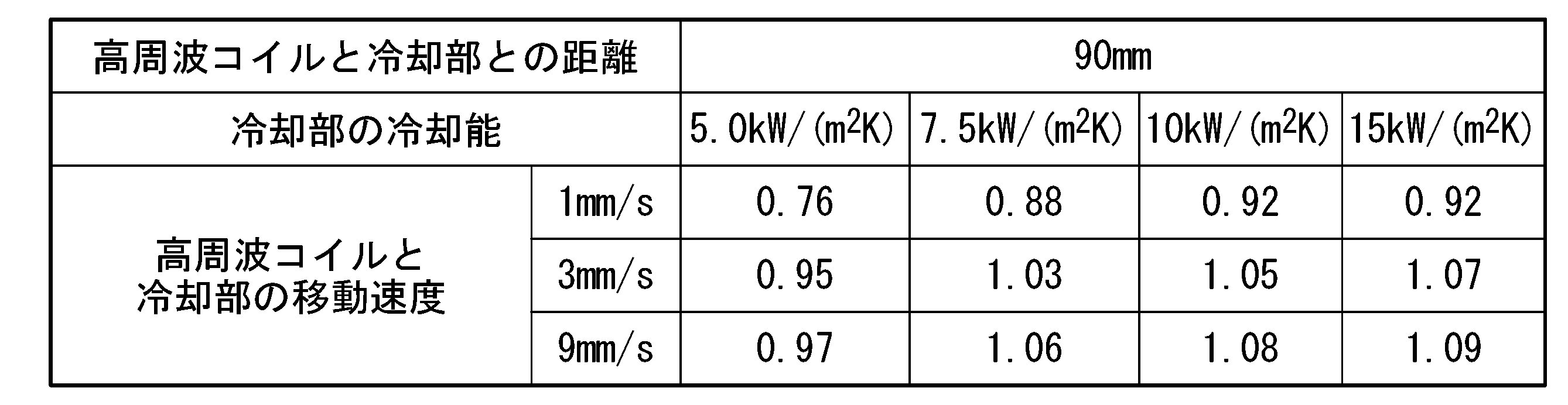
- Example 3 In this example experiment, we will verify the hardening state when moving hardening is performed on a cylindrical shaft-like body made of carbon steel and having a constant outer diameter (170 mm) using a moving hardening device equipped with multiple high-frequency coils. For this purpose, we conducted an analysis using numerical simulation. The shape of the high-frequency induction part of the high-frequency coil was set along the outer diameter of the shaft-like body, and the number of high-frequency coils was three.
- the method for evaluating surface hardness and hardening depth is to obtain the temperature distribution of the shaft-shaped body through magnetic field analysis and heat transfer analysis, and to estimate the phase transformation from the time-series changes in the temperature distribution of each part of the shaft-shaped body. This was done by calculating the hardness after cooling.
- Tables 3 and 4 show the ratio of surface hardness when the hardness of 90% martensite fraction is 1, and Tables 5 and 6 show the thickness from the surface ( mm, firing depth).
- the cooling capacity of the cooling section in the table means the convective heat transfer coefficient of the shaft-like body surface.
- the distance between the high frequency coil and the cooling section was set as specified in the above embodiment. Further, the high frequency coil and the cooling unit were assumed to move at the same speed shown in the table in the axial direction of the shaft-like body.
- the hardness due to quenching tends to decrease as the moving speed of the high-frequency coil and the cooling section decreases.
- the distance between the high frequency coil and the cooling section is shortened, the decrease in hardness can be suppressed. From this, when the shaft-like body has a stepped portion, the axial speed of the high-frequency coil when the high-frequency coil passes through the stepped portion is the same as that of the high-frequency coil when the high-frequency coil passes through the small diameter portion or the large diameter portion.
- the distance between the high-frequency coil and the cooling section in the axial direction of the shaft-like body when the high-frequency coil passes through the stepped part when the speed in the axial direction is smaller than the speed in the small diameter part or the large diameter part It can be seen that quenching hardness can be ensured by making the distance between the high frequency coil and the cooling section smaller than the distance in the axial direction.
- the hardness due to quenching tends to decrease when the moving speed of the high-frequency coil and the cooling section becomes slower, but the hardness due to quenching tends to decrease by improving the cooling capacity of the cooling section. can suppress the decrease in For this reason, the injection amount or injection pressure of the cooling medium when the high-frequency coil passes through the stepped portion is made smaller than the injection amount or injection pressure of the cooling medium when the high-frequency coil passes through the small diameter portion or the large diameter portion. It can be seen that the quenching hardness can be guaranteed by this.
- the depth of quenching can be kept constant by adjusting the cooling capacity of the cooling section according to the moving speed of the coil and the cooling section.
- the convective heat transfer coefficient was adjusted according to the quenching depth of 5 mm.
- the convective heat transfer coefficient was adjusted according to the quenching depth of 3 mm.
- the moving hardening method and moving hardening apparatus of the present invention it is possible to perform desired hardening on the stepped portion and the vicinity of the stepped portion of the shaft-shaped body whose outer diameter is not constant in the axial direction, so that the industrial value thereof is high. Extremely high.
- 100 mobility baking devices 110 Heated portion 111a, 111a, 211a, 211B, 211c high frequency coil 112a, 212B, 212a, 212B, 212c High frequency inducing department 113a, 113B, 113D, 213A, 213b, 213D, 213d, 213E, 213E f -conduct Part 120 Cooling part 130 Support part 140 Heating part moving device 150 Cooling part moving device 160 Control part 10 Shaft-like bodies 11A, 11B Large diameter part 12 Small diameter part 13A, 13B Step part
Landscapes
- Chemical & Material Sciences (AREA)
- Engineering & Computer Science (AREA)
- Physics & Mathematics (AREA)
- Mechanical Engineering (AREA)
- Metallurgy (AREA)
- Thermal Sciences (AREA)
- Crystallography & Structural Chemistry (AREA)
- Materials Engineering (AREA)
- Organic Chemistry (AREA)
- Electromagnetism (AREA)
- Power Engineering (AREA)
- General Engineering & Computer Science (AREA)
- Heat Treatment Of Articles (AREA)
Abstract
Description
前記複数の高周波コイルの内側に挿通した前記軸状体を前記複数の高周波コイルに対して相対的に回転させかつ、前記複数の高周波コイルを前記軸状体に対して前記軸方向に相対的に移動させながら、前記高周波コイルによって前記軸状体を加熱し、
前記軸状体の前記軸方向に沿って前記高周波コイルの相対的な移動方向の後方から前記高周波コイルに前記冷却部を追従させ、前記高周波コイルによって加熱された箇所を前記冷却部によって冷却し、
前記軸状体の表面からそれぞれの前記高周波コイルまでの距離が一定となるように、前記軸状体の前記軸方向と直交する方向へ前記高周波コイルを移動させながら移動焼入れを行い、
前記高周波コイルが前記段差部を通過するときの前記高周波コイルの前記軸方向の速度が、前記高周波コイルが前記小径部又は前記大径部を通過するときの前記高周波コイルの前記軸方向の速度よりも小さい、ことを特徴とする。
(2)(1)に記載の移動焼入れ方法では、前記高周波コイルが前記小径部又は前記大径部を通過するときの前記高周波コイルの前記軸方向の速度をV0、前記高周波コイルが前記段差部を通過するときの前記高周波コイルの前記軸方向の速度をVs、前記複数の高周波コイルの前記軸方向と直交する方向の速度をVcとしたとき、下記の式1が成り立ってもよい。
V02≦Vs2+Vc2 ・・・式1
(3)(1)又は(2)に記載の移動焼入れ方法では、前記高周波コイルが前記段差部を通過するときの前記軸方向における前記高周波コイルと前記冷却部との距離を、前記高周波コイルが前記小径部又は前記大径部を通過するときの前記軸方向における前記高周波コイルと前記冷却部との距離よりも小さくしてもよい。
(4)(1)から(3)のいずれか1項に記載の移動焼入れ方法では、前記冷却部が冷却媒体を噴射し、
前記高周波コイルが前記段差部を通過するときの前記冷却媒体の噴射量又は噴出圧力を、前記高周波コイルが前記小径部又は前記大径部を通過するときの前記冷却媒体の噴射量又は噴出圧力よりも小さくしてもよい。
前記移動焼入れ装置は、
前記軸方向において、複数の高周波コイルと冷却部とを備え、
前記複数の高周波コイルと前記冷却部の移動を制御可能な制御部を備え、
それぞれの前記高周波コイルは、前記軸状体を加熱するための高周波誘導部と前記高周波誘導部に接続された導電部とを有し、前記軸状体に対して前記軸方向に相対的に移動可能でありかつ、前記軸方向に対して垂直な平面において相対的に移動可能であり、
前記冷却部は、冷却媒体を噴射可能な噴射部を有し、前記軸状体に対して前記軸方向に相対的に移動可能であり、
前記制御部は、
前記軸状体の表面からそれぞれの前記高周波コイルまでの距離が一定となるように、前記平面において前記高周波コイルの移動を制御可能でありかつ、
前記高周波コイルが前記段差部を通過するときの前記高周波コイルの前記軸方向の速度が、前記高周波コイルが前記小径部又は前記大径部を通過するときの前記高周波コイルの前記軸方向の速度よりも小さくなるように制御可能であることを特徴とする。
(6)(5)に記載の移動焼入れ装置では、前記制御部が、前記高周波コイルが前記小径部又は前記大径部を通過するときの前記高周波コイルの前記軸方向の速度をV0、前記高周波コイルが前記段差部を通過するときの前記高周波コイルの前記軸方向の速度をVs、前記複数の高周波コイルの前記軸方向と直交する方向の速度をVcとしたとき、下記の式1が成り立つように前記高周波コイルを制御可能であってもよい。
V02≦Vs2+Vc2 ・・・式1
(7)(5)又は(6)に記載の移動焼入れ装置では、前記制御部が、前記高周波コイルが前記段差部を通過するときの前記軸方向における前記高周波コイルと前記冷却部との距離を、前記高周波コイルが前記小径部又は前記大径部を通過するときの前記軸方向における前記高周波コイルと前記冷却部との距離よりも小さくなるように制御可能であってもよい。
(8)(5)から(7)のいずれか1項に記載の移動焼入れ装置では、前記制御部が、前記高周波コイルが前記段差部を通過するときの前記冷却媒体の噴射量又は噴出圧力を、前記高周波コイルが前記小径部又は前記大径部を通過するときの前記冷却媒体の噴射量又は噴出圧力よりも小さくなるように制御可能であってもよい。
軸状体10は、大径部11(大径部11A及び大径部11B)と、軸線Cに沿った方向において大径部11A及び大径部11Bの間に設けられた小径部12とを備えている。大径部11A、大径部11B及び小径部12は、それぞれ円柱状に形成されている。大径部11A、大径部11B及び小径部12のそれぞれの中心軸は、共通する軸線である軸線Cに一致するように配置されている。本実施形態においては、軸線Cを軸状体10の中心軸とする。以下では、小径部12に対して軸線Cに沿った方向の一方側D1に配置された部分を、第1大径部11Aとも称する。小径部12に対して軸線Cに沿った方向の他方側D2に配置された部分を、第2大径部11Bとも称する。
なお、軸状体10が備える大径部11や段差部13等の数は、図1の例に限定されない。小径部12、大径部11、段差部13の数はそれぞれ、1、2又は3でもよいし、4以上であってもよい。例えば、本実施形態の移動焼入れ方法及び移動焼入れ装置の対象となる軸状体は、1つの大径部と1つの小径部とを備える軸状体であってもよい。
移動焼入れ装置100は、加熱部110と、冷却部120と、支持部130と、加熱部移動装置140と、冷却部移動装置150と、制御部160とを備えている。図1に示すように、加熱部110は、複数の高周波コイル111(高周波コイル111A及び高周波コイル111B)を備えている。加熱部110は、移動手段である加熱部移動装置140に接続されている。冷却部120は、冷却環121を備えている。冷却部120は、移動手段である冷却部移動装置150に接続されている。支持部130は、上方センター131と、下方センター132と、を備えている。上方センター131は、軸状体10の第1大径部11Aを第1大径部11Aの上方から支持している。下方センター132は、軸状体10の第2大径部11Bを第2大径部11Bの下方から支持している。上方センター131と下方センター132は、軸線C方向の一方側D1が上方、他方側D2が下方となるように軸状体10を支持している。なお、軸状体10は、上方センター131と下方センター132によって支持された状態で、軸線Cを中心とした軸状体10の周方向に回転可能である。上方センター131と下方センター132を介して、駆動装置(図示せず)によって、移動焼き入れ時に軸状体10を軸状体10の軸周りに回転させることができる。軸状体10を軸周りに回転させるとは、軸状体10の軸線Cを中心とする周方向のいずれかに軸状体10を回転させることを意味する。上方センター131の中心と下方センター132の中心とを結ぶ線は移動焼入れ装置100の上下方向(上下方向とも称する)となる。
本実施形態の加熱部110は、複数の高周波コイルを備えている。図2に、加熱部110が備える高周波コイル111A及び高周波コイル111Bと軸状体10とを軸線Cに沿った方向に図1のA-A方向(軸方向と平行な方向)から見た模式的な平面図を示す。図2において軸状体10は小径部12の途中で破断した状態で示されている。図2に示すように、加熱部110が備える高周波コイル111A及び高周波コイル111Bは、軸状体10の軸線Cに沿った方向から見た平面視で、その一部が軸状体10を囲むようにC字形に形成された高周波誘導部112A及び高周波誘導部112Bを有している。高周波誘導部112Aはその端部で導電部113a及び113bへ接続されている。高周波誘導部112Bも同様に、その端部で導電部113c及び113dへ接続されている。
高周波コイル111は、非磁性で渦電流損が生じにくく、電気抵抗が小さくジュール損も生じにくい材料であるという理由から、銅などの材料で形成されていることが好ましい。なお、高周波コイル111の間もしくは高周波コイル111と軸状体10が接触しても短絡しないように、高周波コイル111の表面を耐熱性があり絶縁性が高いベークライトやシリコンなどの素材で覆ってもよい。
冷却部120は、加熱部110の相対的な移動方向の後方に配置されている。相対的な移動方向とは、移動焼入れ時に加熱部110が軸状体10に対して軸方向に相対的に移動する方向を意味する。本実施形態の場合は、加熱部110は図1のD1の方向へ移動しながら移動焼入れを実施するため、図1に示すように、冷却部120は加熱部110の下側に配置されている。図6に、本実施形態における軸状体10に対する加熱部110と冷却部120の位置関係を例示する。
V12=V1x2+V1z2 ・・・式A
ここで、V1xは高周波コイル111が段差部13を通過するときのX座標成分の速度であり、V1zは高周波コイル111が段差部13を通過するときのZ座標成分の速度である。
V0z2≦V1x2+V1z2 ・・・式B
高周波コイル111に流す電流によって被加熱体である軸状体10に生じる渦電流により、被加熱体の表面が発熱するが、上記のように単位時間あたりの移動距離を一定に保つことにより軸状体10の表面単位長さにおける単位時間あたりの該発熱エネルギーも一定となる。
V02≦Vs2+Vc2 ・・・式1
Vsは上記のV1zと同じであり、Vcは上記のV1xと同じである。
また、複数の高周波コイル111は、横平面において、互いに同じ速度で移動することが好ましい。
冷却の態様としては、CCT曲線上での冷却速度が、硬度変化が生じない範囲に抑えられるように、冷却媒体Clの噴出量もしくは噴出圧力を調整して冷却能を制御することが望ましい。より具体的には、高周波コイル111の軸方向の移動速度が速い場合は、冷却媒体Clの噴出量を多くするか又は冷却媒体Clの噴出圧力を強くし、加熱コイルの軸方向の移動速度が遅い場合は、冷却媒体Clの噴出量を少なくするか又は冷却媒体Clの噴出圧力を弱くする。熱伝達係数hと噴射水量(水量密度)Wの関係は、例えば、hはWのn乗(nは水冷条件によって決まる定数)に比例することが示されている(三塚:高温鋼材の冷却技術,鉄と鋼/79巻6号,p.N405-N416(1993))。ここで、冷却部120の移動速度が速いと、単位時間あたりの冷却能力が速度に反比例して落ちるため、速度上昇率の分だけ熱伝達係数hが大きくなるようにWnの噴射水量Wを決める。このようにすると、冷却部120の移動速度によらず冷却能力を一定に保てるため、被加熱体の冷却速度を望ましい範囲に保つことができる。
V02≦Vs2+Vc2 ・・・式1
上述の移動焼入れ装置の使用においては、制御部が、高周波コイルが段差部を通過するときの軸方向における高周波コイルと冷却部との距離を、高周波コイルが小径部又は大径部を通過するときの軸方向における高周波コイルと冷却部との距離よりも小さくなるように制御可能であってもよい。
上述の移動焼入れ装置の使用においては、制御部が、高周波コイルが段差部を通過するときの冷却媒体の噴射量又は噴出圧力を、高周波コイルが小径部又は大径部を通過するときの冷却媒体の噴射量又は噴出圧力よりも小さくなるように制御可能であってもよい。
複数の高周波コイルを備える移動焼入れ装置を用いて、軸方向において小径部と、大径部と、前記小径部と大径部とを接続する段差部とを有する軸状体に移動焼入れを行ったときの段差部における加熱状態を検証するために、数値シミュレーションによる解析を行った。本実験例では、軸状体は、炭素鋼製であり、小径部の外径170mm、大径部の外径200mmとした。高周波コイルの数は4とした。

実験例1と同様の数値シミュレーションによる解析を行った。本実験例では、実験例1と同じ軸状体と高周波コイルを採用した。軸状体の軸方向と軸方向に垂直な方向における高周波コイルの移動速度を制御することで、高周波コイルの軸状体の表面からの距離が一定となるようにした点は実験例1と同様である。

本実験例では、複数の高周波コイルを備える移動焼入れ装置を用いて、炭素鋼製、一定の外径(170mm)を有する円柱状の軸状体に移動焼入れを行ったときの焼入れ状態を検証するために、数値シミュレーションによる解析を行った。高周波コイルの高周波誘導部の形状は軸状体の外径に沿ったものとし、高周波コイルの数は3とした。



110 加熱部
111A、111B、211A、211B、211C 高周波コイル
112A、112B、212A、212B、212C 高周波誘導部
113a、113b、113c、113d、213a、213b、213c、213d、213e、213f 導電部
120 冷却部
130 支持部
140 加熱部移動装置
150 冷却部移動装置
160 制御部
10 軸状体
11A、11B 大径部
12 小径部
13A、13B 段差部
Claims (8)
- 複数の高周波コイルと冷却部とを備える移動焼入れ装置を用いて、軸方向において小径部と、大径部と、前記小径部と前記大径部とを接続する段差部とを有する軸状体を焼入れする移動焼入れ方法であって、
前記複数の高周波コイルの内側に挿通した前記軸状体を前記複数の高周波コイルに対して相対的に回転させかつ、前記複数の高周波コイルを前記軸状体に対して前記軸方向に相対的に移動させながら、前記高周波コイルによって前記軸状体を加熱し、
前記軸状体の前記軸方向に沿って前記高周波コイルの相対的な移動方向の後方から前記高周波コイルに前記冷却部を追従させ、前記高周波コイルによって加熱された箇所を前記冷却部によって冷却し、
前記軸状体の表面からそれぞれの前記高周波コイルまでの距離が一定となるように、前記軸状体の前記軸方向と直交する方向へ前記高周波コイルを移動させながら移動焼入れを行い、
前記高周波コイルが前記段差部を通過するときの前記高周波コイルの前記軸方向の速度が、前記高周波コイルが前記小径部又は前記大径部を通過するときの前記高周波コイルの前記軸方向の速度よりも小さい、
ことを特徴とする移動焼入れ方法。 - 前記高周波コイルが前記小径部又は前記大径部を通過するときの前記高周波コイルの前記軸方向の速度をV0、前記高周波コイルが前記段差部を通過するときの前記高周波コイルの前記軸方向の速度をVs、前記複数の高周波コイルの前記軸方向と直交する方向の速度をVcとしたとき、下記の式1が成り立つ
ことを特徴とする請求項1に記載の移動焼入れ方法。
V02≦Vs2+Vc2 ・・・式1 - 前記高周波コイルが前記段差部を通過するときの前記軸方向における前記高周波コイルと前記冷却部との距離を、前記高周波コイルが前記小径部又は前記大径部を通過するときの前記軸方向における前記高周波コイルと前記冷却部との距離よりも小さくする
ことを特徴とする請求項1又は2に記載の移動焼入れ方法。 - 前記冷却部が冷却媒体を噴射し、
前記高周波コイルが前記段差部を通過するときの前記冷却媒体の噴射量又は噴出圧力を、前記高周波コイルが前記小径部又は前記大径部を通過するときの前記冷却媒体の噴射量又は噴出圧力よりも小さくする
ことを特徴とする請求項1から3のいずれか1項に記載の移動焼入れ方法。 - 軸方向において小径部と、大径部と、前記小径部と前記大径部とを接続する段差部とを有する軸状体を焼入れするための移動焼入れ装置であって、
前記移動焼入れ装置は、
前記軸方向において、複数の高周波コイルと冷却部とを備え、
前記複数の高周波コイルと前記冷却部の移動を制御可能な制御部を備え、
それぞれの前記高周波コイルは、前記軸状体を加熱するための高周波誘導部と前記高周波誘導部に接続された導電部とを有し、前記軸状体に対して前記軸方向に相対的に移動可能でありかつ、前記軸方向に対して垂直な平面において相対的に移動可能であり、
前記冷却部は、冷却媒体を噴射可能な噴射部を有し、前記軸状体に対して前記軸方向に相対的に移動可能であり、
前記制御部は、
前記軸状体の表面からそれぞれの前記高周波コイルまでの距離が一定となるように、前記平面において前記高周波コイルの移動を制御可能でありかつ、
前記高周波コイルが前記段差部を通過するときの前記高周波コイルの前記軸方向の速度が、前記高周波コイルが前記小径部又は前記大径部を通過するときの前記高周波コイルの前記軸方向の速度よりも小さくなるように制御可能である
ことを特徴とする移動焼入れ装置。 - 前記制御部が、前記高周波コイルが前記小径部又は前記大径部を通過するときの前記高周波コイルの前記軸方向の速度をV0、前記高周波コイルが前記段差部を通過するときの前記高周波コイルの前記軸方向の速度をVs、前記複数の高周波コイルの前記軸方向と直交する方向の速度をVcとしたとき、下記の式1が成り立つように前記高周波コイルを制御可能である
ことを特徴とする請求項5に記載の移動焼入れ装置。
V02≦Vs2+Vc2 ・・・式1 - 前記制御部が、前記高周波コイルが前記段差部を通過するときの前記軸方向における前記高周波コイルと前記冷却部との距離を、前記高周波コイルが前記小径部又は前記大径部を通過するときの前記軸方向における前記高周波コイルと前記冷却部との距離よりも小さくなるように制御可能である
ことを特徴とする請求項5又は6に記載の移動焼入れ装置。 - 前記制御部が、前記高周波コイルが前記段差部を通過するときの前記冷却媒体の噴射量又は噴出圧力を、前記高周波コイルが前記小径部又は前記大径部を通過するときの前記冷却媒体の噴射量又は噴出圧力よりも小さくなるように制御可能である
ことを特徴とする請求項5から7のいずれか1項に記載の移動焼入れ装置。
Priority Applications (4)
| Application Number | Priority Date | Filing Date | Title |
|---|---|---|---|
| PCT/JP2022/034240 WO2024057406A1 (ja) | 2022-09-13 | 2022-09-13 | 移動焼入れ方法及び移動焼入れ装置 |
| EP22958740.7A EP4589030A4 (en) | 2022-09-13 | 2022-09-13 | MOBILE CURING METHOD AND MOBILE CURING DEVICE |
| CN202280099870.1A CN119855925A (zh) | 2022-09-13 | 2022-09-13 | 移动淬火方法以及移动淬火装置 |
| JP2024546562A JPWO2024057406A1 (ja) | 2022-09-13 | 2022-09-13 |
Applications Claiming Priority (1)
| Application Number | Priority Date | Filing Date | Title |
|---|---|---|---|
| PCT/JP2022/034240 WO2024057406A1 (ja) | 2022-09-13 | 2022-09-13 | 移動焼入れ方法及び移動焼入れ装置 |
Publications (1)
| Publication Number | Publication Date |
|---|---|
| WO2024057406A1 true WO2024057406A1 (ja) | 2024-03-21 |
Family
ID=90274478
Family Applications (1)
| Application Number | Title | Priority Date | Filing Date |
|---|---|---|---|
| PCT/JP2022/034240 Ceased WO2024057406A1 (ja) | 2022-09-13 | 2022-09-13 | 移動焼入れ方法及び移動焼入れ装置 |
Country Status (4)
| Country | Link |
|---|---|
| EP (1) | EP4589030A4 (ja) |
| JP (1) | JPWO2024057406A1 (ja) |
| CN (1) | CN119855925A (ja) |
| WO (1) | WO2024057406A1 (ja) |
Citations (8)
| Publication number | Priority date | Publication date | Assignee | Title |
|---|---|---|---|---|
| JPS3610457B1 (en) | 1959-04-28 | 1961-07-13 | High-frequency hardening inductor | |
| CN1600873A (zh) * | 2003-09-26 | 2005-03-30 | 上海纳铁福传动轴有限公司 | 阶梯轴感应加热淬火装置及方法 |
| JP2005344159A (ja) * | 2004-06-02 | 2005-12-15 | High Frequency Heattreat Co Ltd | 誘導加熱による異径軸部材の外周焼入方法及び焼入装置 |
| JP2008150640A (ja) | 2006-12-14 | 2008-07-03 | Denki Kogyo Co Ltd | 軸状部材加熱用の高周波誘導加熱コイル及びこの高周波誘導加熱コイルを用いた高周波誘導加熱装置 |
| JP2009019230A (ja) * | 2007-07-11 | 2009-01-29 | Komatsu Ltd | ワークの製造方法 |
| JP2015108188A (ja) * | 2013-10-25 | 2015-06-11 | 高周波熱錬株式会社 | 誘導加熱装置及び方法並びに熱処理装置及び方法 |
| JP2016089262A (ja) * | 2014-11-11 | 2016-05-23 | 高周波熱錬株式会社 | 焼入れ装置及び焼入れ方法 |
| WO2019181382A1 (ja) * | 2018-03-23 | 2019-09-26 | 日本製鉄株式会社 | 移動焼入れ装置及び移動焼入れ方法 |
Family Cites Families (5)
| Publication number | Priority date | Publication date | Assignee | Title |
|---|---|---|---|---|
| JPS499285B1 (ja) * | 1967-07-22 | 1974-03-04 | ||
| JPH0382713A (ja) * | 1989-08-25 | 1991-04-08 | Fuji Denshi Kogyo Kk | 高周波焼入コイル |
| JP4926728B2 (ja) * | 2007-01-15 | 2012-05-09 | 高周波熱錬株式会社 | スプラインシャフト、熱処理方法および熱処理装置 |
| JP6438734B2 (ja) * | 2014-10-29 | 2018-12-19 | 高周波熱錬株式会社 | ワークの加熱方法及び焼入方法 |
| US20250318020A1 (en) * | 2022-06-28 | 2025-10-09 | Nippon Steel Corporation | Traverse hardening device and traverse hardening method |
-
2022
- 2022-09-13 CN CN202280099870.1A patent/CN119855925A/zh active Pending
- 2022-09-13 WO PCT/JP2022/034240 patent/WO2024057406A1/ja not_active Ceased
- 2022-09-13 JP JP2024546562A patent/JPWO2024057406A1/ja active Pending
- 2022-09-13 EP EP22958740.7A patent/EP4589030A4/en active Pending
Patent Citations (8)
| Publication number | Priority date | Publication date | Assignee | Title |
|---|---|---|---|---|
| JPS3610457B1 (en) | 1959-04-28 | 1961-07-13 | High-frequency hardening inductor | |
| CN1600873A (zh) * | 2003-09-26 | 2005-03-30 | 上海纳铁福传动轴有限公司 | 阶梯轴感应加热淬火装置及方法 |
| JP2005344159A (ja) * | 2004-06-02 | 2005-12-15 | High Frequency Heattreat Co Ltd | 誘導加熱による異径軸部材の外周焼入方法及び焼入装置 |
| JP2008150640A (ja) | 2006-12-14 | 2008-07-03 | Denki Kogyo Co Ltd | 軸状部材加熱用の高周波誘導加熱コイル及びこの高周波誘導加熱コイルを用いた高周波誘導加熱装置 |
| JP2009019230A (ja) * | 2007-07-11 | 2009-01-29 | Komatsu Ltd | ワークの製造方法 |
| JP2015108188A (ja) * | 2013-10-25 | 2015-06-11 | 高周波熱錬株式会社 | 誘導加熱装置及び方法並びに熱処理装置及び方法 |
| JP2016089262A (ja) * | 2014-11-11 | 2016-05-23 | 高周波熱錬株式会社 | 焼入れ装置及び焼入れ方法 |
| WO2019181382A1 (ja) * | 2018-03-23 | 2019-09-26 | 日本製鉄株式会社 | 移動焼入れ装置及び移動焼入れ方法 |
Non-Patent Citations (1)
| Title |
|---|
| See also references of EP4589030A4 |
Also Published As
| Publication number | Publication date |
|---|---|
| CN119855925A (zh) | 2025-04-18 |
| EP4589030A4 (en) | 2025-10-22 |
| EP4589030A1 (en) | 2025-07-23 |
| JPWO2024057406A1 (ja) | 2024-03-21 |
Similar Documents
| Publication | Publication Date | Title |
|---|---|---|
| MX2012011957A (es) | Tratamiento termico por induccion de una pieza de trabajo anular. | |
| EP3770285A1 (en) | Traverse hardening device and traverse hardening method | |
| CN105648190B (zh) | 一种提高钢管内壁硬度的方法 | |
| CN106031301B (zh) | 热处理装置以及热处理方法 | |
| JP2008169430A (ja) | 鋼球の熱処理装置および鋼球の熱処理方法 | |
| CN109317631B (zh) | 改善连铸方坯组织均匀性的生产方法 | |
| CN113874530B (zh) | 移动淬火装置及移动淬火方法 | |
| WO2024057406A1 (ja) | 移動焼入れ方法及び移動焼入れ装置 | |
| JP2001032017A (ja) | 高周波焼入れ装置 | |
| CN114072529B (zh) | 移动淬火装置及移动淬火方法 | |
| WO2024057405A1 (ja) | 移動焼入れ方法及び移動焼入れ装置 | |
| JP2009019237A (ja) | 高周波焼入装置及び部材の製造方法 | |
| JP2008169431A (ja) | 鋼球の熱処理装置および鋼球の熱処理方法 | |
| US20250318020A1 (en) | Traverse hardening device and traverse hardening method | |
| JP4658027B2 (ja) | 軸状部材加熱用の高周波誘導加熱コイル | |
| JP2011021242A (ja) | 高周波誘導加熱方法及び高周波誘導加熱装置 | |
| JP5527154B2 (ja) | 軸状部材の高周波焼入装置 | |
| JP3222016U (ja) | 曲げ加工管の製造装置 | |
| JP5496478B2 (ja) | 高周波誘導加熱焼戻装置及び高周波誘導加熱焼戻方法 | |
| JP3159478B2 (ja) | 鋼球の表面均一加熱方法 | |
| JPWO2024057406A5 (ja) | ||
| JP3936532B2 (ja) | 大型球面の誘導加熱焼入方法及び加熱コイル | |
| Scarpellini et al. | Ultra Large Bearings: a complete range of seamless induction heating solutions | |
| JP5903455B2 (ja) | 熱処理装置および熱処理方法 | |
| Eimuss et al. | Does 3D-Printed Coil Perform Better for Induction Hardening and How to Predict the Performance Based on Numerical Simulation? |
Legal Events
| Date | Code | Title | Description |
|---|---|---|---|
| 121 | Ep: the epo has been informed by wipo that ep was designated in this application |
Ref document number: 22958740 Country of ref document: EP Kind code of ref document: A1 |
|
| WWE | Wipo information: entry into national phase |
Ref document number: 2024546562 Country of ref document: JP |
|
| WWE | Wipo information: entry into national phase |
Ref document number: 202280099870.1 Country of ref document: CN |
|
| WWE | Wipo information: entry into national phase |
Ref document number: 2022958740 Country of ref document: EP |
|
| NENP | Non-entry into the national phase |
Ref country code: DE |
|
| WWP | Wipo information: published in national office |
Ref document number: 202280099870.1 Country of ref document: CN |
|
| ENP | Entry into the national phase |
Ref document number: 2022958740 Country of ref document: EP Effective date: 20250414 |
|
| WWP | Wipo information: published in national office |
Ref document number: 2022958740 Country of ref document: EP |