WO2024057645A1 - 車両用パーキング装置 - Google Patents
車両用パーキング装置 Download PDFInfo
- Publication number
- WO2024057645A1 WO2024057645A1 PCT/JP2023/022284 JP2023022284W WO2024057645A1 WO 2024057645 A1 WO2024057645 A1 WO 2024057645A1 JP 2023022284 W JP2023022284 W JP 2023022284W WO 2024057645 A1 WO2024057645 A1 WO 2024057645A1
- Authority
- WO
- WIPO (PCT)
- Prior art keywords
- driven gear
- parking
- link member
- rotation
- side end
- Prior art date
- Legal status (The legal status is an assumption and is not a legal conclusion. Google has not performed a legal analysis and makes no representation as to the accuracy of the status listed.)
- Ceased
Links
Images




Classifications
-
- F—MECHANICAL ENGINEERING; LIGHTING; HEATING; WEAPONS; BLASTING
- F16—ENGINEERING ELEMENTS AND UNITS; GENERAL MEASURES FOR PRODUCING AND MAINTAINING EFFECTIVE FUNCTIONING OF MACHINES OR INSTALLATIONS; THERMAL INSULATION IN GENERAL
- F16H—GEARING
- F16H63/00—Control outputs from the control unit to change-speed- or reversing-gearings for conveying rotary motion or to other devices than the final output mechanism
- F16H63/02—Final output mechanisms therefor; Actuating means for the final output mechanisms
- F16H63/30—Constructional features of the final output mechanisms
- F16H63/34—Locking or disabling mechanisms
- F16H63/3416—Parking lock mechanisms or brakes in the transmission
- F16H63/3458—Parking lock mechanisms or brakes in the transmission with electric actuating means, e.g. shift by wire
- F16H63/3466—Parking lock mechanisms or brakes in the transmission with electric actuating means, e.g. shift by wire using electric motors
-
- B—PERFORMING OPERATIONS; TRANSPORTING
- B60—VEHICLES IN GENERAL
- B60T—VEHICLE BRAKE CONTROL SYSTEMS OR PARTS THEREOF; BRAKE CONTROL SYSTEMS OR PARTS THEREOF, IN GENERAL; ARRANGEMENT OF BRAKING ELEMENTS ON VEHICLES IN GENERAL; PORTABLE DEVICES FOR PREVENTING UNWANTED MOVEMENT OF VEHICLES; VEHICLE MODIFICATIONS TO FACILITATE COOLING OF BRAKES
- B60T1/00—Arrangements of braking elements, i.e. of those parts where braking effect occurs specially for vehicles
- B60T1/005—Arrangements of braking elements, i.e. of those parts where braking effect occurs specially for vehicles by locking of wheel or transmission rotation
-
- B—PERFORMING OPERATIONS; TRANSPORTING
- B60—VEHICLES IN GENERAL
- B60T—VEHICLE BRAKE CONTROL SYSTEMS OR PARTS THEREOF; BRAKE CONTROL SYSTEMS OR PARTS THEREOF, IN GENERAL; ARRANGEMENT OF BRAKING ELEMENTS ON VEHICLES IN GENERAL; PORTABLE DEVICES FOR PREVENTING UNWANTED MOVEMENT OF VEHICLES; VEHICLE MODIFICATIONS TO FACILITATE COOLING OF BRAKES
- B60T1/00—Arrangements of braking elements, i.e. of those parts where braking effect occurs specially for vehicles
- B60T1/02—Arrangements of braking elements, i.e. of those parts where braking effect occurs specially for vehicles acting by retarding wheels
- B60T1/06—Arrangements of braking elements, i.e. of those parts where braking effect occurs specially for vehicles acting by retarding wheels acting otherwise than on tread, e.g. employing rim, drum, disc, or transmission or on double wheels
- B60T1/062—Arrangements of braking elements, i.e. of those parts where braking effect occurs specially for vehicles acting by retarding wheels acting otherwise than on tread, e.g. employing rim, drum, disc, or transmission or on double wheels acting on transmission parts
-
- F—MECHANICAL ENGINEERING; LIGHTING; HEATING; WEAPONS; BLASTING
- F16—ENGINEERING ELEMENTS AND UNITS; GENERAL MEASURES FOR PRODUCING AND MAINTAINING EFFECTIVE FUNCTIONING OF MACHINES OR INSTALLATIONS; THERMAL INSULATION IN GENERAL
- F16D—COUPLINGS FOR TRANSMITTING ROTATION; CLUTCHES; BRAKES
- F16D63/00—Brakes not otherwise provided for; Brakes combining more than one of the types of groups F16D49/00 - F16D61/00
- F16D63/006—Positive locking brakes
-
- F—MECHANICAL ENGINEERING; LIGHTING; HEATING; WEAPONS; BLASTING
- F16—ENGINEERING ELEMENTS AND UNITS; GENERAL MEASURES FOR PRODUCING AND MAINTAINING EFFECTIVE FUNCTIONING OF MACHINES OR INSTALLATIONS; THERMAL INSULATION IN GENERAL
- F16D—COUPLINGS FOR TRANSMITTING ROTATION; CLUTCHES; BRAKES
- F16D65/00—Parts or details
- F16D65/14—Actuating mechanisms for brakes; Means for initiating operation at a predetermined position
- F16D65/28—Actuating mechanisms for brakes; Means for initiating operation at a predetermined position arranged apart from the brake
-
- F—MECHANICAL ENGINEERING; LIGHTING; HEATING; WEAPONS; BLASTING
- F16—ENGINEERING ELEMENTS AND UNITS; GENERAL MEASURES FOR PRODUCING AND MAINTAINING EFFECTIVE FUNCTIONING OF MACHINES OR INSTALLATIONS; THERMAL INSULATION IN GENERAL
- F16H—GEARING
- F16H63/00—Control outputs from the control unit to change-speed- or reversing-gearings for conveying rotary motion or to other devices than the final output mechanism
- F16H63/02—Final output mechanisms therefor; Actuating means for the final output mechanisms
- F16H63/30—Constructional features of the final output mechanisms
- F16H63/34—Locking or disabling mechanisms
- F16H63/3416—Parking lock mechanisms or brakes in the transmission
- F16H63/3425—Parking lock mechanisms or brakes in the transmission characterised by pawls or wheels
-
- F—MECHANICAL ENGINEERING; LIGHTING; HEATING; WEAPONS; BLASTING
- F16—ENGINEERING ELEMENTS AND UNITS; GENERAL MEASURES FOR PRODUCING AND MAINTAINING EFFECTIVE FUNCTIONING OF MACHINES OR INSTALLATIONS; THERMAL INSULATION IN GENERAL
- F16D—COUPLINGS FOR TRANSMITTING ROTATION; CLUTCHES; BRAKES
- F16D2121/00—Type of actuator operation force
- F16D2121/18—Electric or magnetic
- F16D2121/24—Electric or magnetic using motors
-
- F—MECHANICAL ENGINEERING; LIGHTING; HEATING; WEAPONS; BLASTING
- F16—ENGINEERING ELEMENTS AND UNITS; GENERAL MEASURES FOR PRODUCING AND MAINTAINING EFFECTIVE FUNCTIONING OF MACHINES OR INSTALLATIONS; THERMAL INSULATION IN GENERAL
- F16D—COUPLINGS FOR TRANSMITTING ROTATION; CLUTCHES; BRAKES
- F16D2125/00—Components of actuators
- F16D2125/18—Mechanical mechanisms
- F16D2125/20—Mechanical mechanisms converting rotation to linear movement or vice versa
- F16D2125/22—Mechanical mechanisms converting rotation to linear movement or vice versa acting transversely to the axis of rotation
- F16D2125/28—Cams; Levers with cams
-
- F—MECHANICAL ENGINEERING; LIGHTING; HEATING; WEAPONS; BLASTING
- F16—ENGINEERING ELEMENTS AND UNITS; GENERAL MEASURES FOR PRODUCING AND MAINTAINING EFFECTIVE FUNCTIONING OF MACHINES OR INSTALLATIONS; THERMAL INSULATION IN GENERAL
- F16D—COUPLINGS FOR TRANSMITTING ROTATION; CLUTCHES; BRAKES
- F16D2125/00—Components of actuators
- F16D2125/18—Mechanical mechanisms
- F16D2125/44—Mechanical mechanisms transmitting rotation
- F16D2125/46—Rotating members in mutual engagement
- F16D2125/48—Rotating members in mutual engagement with parallel stationary axes, e.g. spur gears
-
- F—MECHANICAL ENGINEERING; LIGHTING; HEATING; WEAPONS; BLASTING
- F16—ENGINEERING ELEMENTS AND UNITS; GENERAL MEASURES FOR PRODUCING AND MAINTAINING EFFECTIVE FUNCTIONING OF MACHINES OR INSTALLATIONS; THERMAL INSULATION IN GENERAL
- F16D—COUPLINGS FOR TRANSMITTING ROTATION; CLUTCHES; BRAKES
- F16D2125/00—Components of actuators
- F16D2125/18—Mechanical mechanisms
- F16D2125/58—Mechanical mechanisms transmitting linear movement
- F16D2125/64—Levers
-
- F—MECHANICAL ENGINEERING; LIGHTING; HEATING; WEAPONS; BLASTING
- F16—ENGINEERING ELEMENTS AND UNITS; GENERAL MEASURES FOR PRODUCING AND MAINTAINING EFFECTIVE FUNCTIONING OF MACHINES OR INSTALLATIONS; THERMAL INSULATION IN GENERAL
- F16H—GEARING
- F16H63/00—Control outputs from the control unit to change-speed- or reversing-gearings for conveying rotary motion or to other devices than the final output mechanism
- F16H63/02—Final output mechanisms therefor; Actuating means for the final output mechanisms
- F16H63/30—Constructional features of the final output mechanisms
- F16H63/34—Locking or disabling mechanisms
Definitions
- the present invention relates to a vehicle parking device, and particularly to a vehicle parking device including a motor.
- a vehicle parking device equipped with a motor is known.
- This vehicle parking device is disclosed in, for example, Japanese Unexamined Patent Publication No. 2022-88011.
- the above-mentioned Japanese Patent Application Publication No. 2022-88011 discloses a vehicle parking device including a motor.
- This vehicle parking device includes a linear movement shaft, a link portion, a lever portion, and a park rod.
- the linear movement axis is configured to move forward and backward in the direction in which the linear movement axis extends by driving a motor.
- One end of the link portion is connected to the linear movement shaft by a first pin.
- the other end of the link part is connected to the one end of the lever part by a second pin.
- the other end of the lever portion is connected to the park rod by a third pin.
- the park rod is driven by the motor to advance and retreat toward a parking position corresponding to a parking locked state and a non-parking position corresponding to a parking unlocked state.
- the link portion and the linear movement axis are perpendicular to each other.
- the orthogonal intersection point which is the intersection of the extending direction of the link part and the extending direction of the linear movement axis, one end of the link part, and the other end of the link part are the first pin.
- they are lined up in a straight line.
- the torque transmitted from the park rod moves in a straight line through the link part. Not transmitted to the shaft.
- the state in which the orthogonal intersection, one end of the link, and the other end of the link are lined up in a straight line indicates that an external force (for example, vehicle vibration) is applied to the park rod. Also, the link part is difficult to move.
- the link part will move when the park rod moves due to an external force.
- the link section may return to the parking lock state position.
- the vehicle parking device disclosed in JP-A No. 2022-88011 has a structure in which the link portion is difficult to move even if an external force is applied to the parking rod only in the parking lock state. Therefore, in the vehicle parking device disclosed in Japanese Patent Application Laid-Open No. 2022-88011, the link portion (link member) is difficult to move even when an external force is applied to the park rod in both the parking lock state and the parking lock release state. It is hoped that a structure will be realized.
- the above-mentioned external force may include an inertial force of parts generated by vehicle vibration, a reaction force when a retraction spring of a parking rod is bent, and the like.
- An object of the present invention is to provide a vehicle parking device that can realize a structure in which a link member is difficult to move.
- a vehicle parking device includes: a motor that generates a driving force for switching a vehicle between a parking lock state and a parking unlock state;
- the transmission mechanism includes a transmission mechanism that transmits driving force, and a park rod that is connected to the transmission mechanism and reciprocates between a parking position corresponding to a parking lock state and a non-parking position corresponding to a parking unlock state.
- a driven gear that rotates around the center axis of rotation due to the driving force from the driven gear, a drive side end that is connected to the driven gear and rotates with the rotation of the driven gear, and
- the link member includes a link member having an output side end that is the other end that rotates, and a first rotation shaft disposed on the rotation center axis of the driven gear, and the link member has a parking lock. It has a relief part that avoids interference with the first rotating shaft while reciprocating between the parking lock release state and the parking lock release state.
- the link member avoids interference with the first rotating shaft while the link member reciprocates between the parking lock state and the parking unlock state. It has a relief part like this.
- the link member in the parking lock state while reciprocating between the parking lock state and the parking lock release state, the link member is placed in a position where the relief part avoids interference with the first rotating shaft, so that the link member is not affected by external force. Even if the park rod tries to move, the link member can block the torque generated due to external force.
- the park rod is moved by external force.
- the link member can block the torque generated due to external force.
- the link member is difficult to move even if an external force is applied to the parking rod in both the parking lock state and the parking lock release state.
- the relief portion prevents the driven gear and the link member from interfering with each other. Can be done.
- the relief portion is bent or curved to avoid interference with the rotating shaft while the link member reciprocates between the parking lock state and the parking unlock state.
- the structure of the relief part that avoids interference between the driven gear and the link member can be realized with a simple structure, so it is possible to suppress the complexity of the structure of the link member.
- the rotation center axis of the driven gear, the drive side end of the link member, and the output side end of the link member are aligned with each other when the driven gear is in the parking lock state. They are arranged in a straight line when viewed from one side in the direction in which the rotation center axis of the gear extends.
- the link member whose drive side end and output side end are aligned in a straight line with respect to the rotation center axis of the driven gear is in a state where no torque is transmitted. Therefore, even if the park rod attempts to move due to an external force, the torque generated due to the external force is blocked by the link member at the point of consideration. As a result, in the parking lock state, the link member does not move even if an external force is applied to the park rod, which is an important point in the link mechanism.
- This structure allows the sensor to detect the movement of the park rod due to external force. There is no need to provide a sensor and drive the motor based on the detection signal of this sensor so that the driven gear does not move. As a result, in the parking lock state, it is not necessary to supply power to the sensor and the motor, so it is possible to suppress power consumption of the vehicle parking device.
- the rotation center axis of the driven gear and the output side end with respect to the rotation center axis of the driven gear are The driving side end of the link member and the output side end of the link member, which are arranged on opposite sides, are lined up in a straight line.
- the drive side end of the link member is located on the output side end side with respect to the rotation center axis of the driven gear, opposite to the output side end.
- the rotation center axis of the driven gear, the drive side end of the link member, and the output side end of the link member are aligned with each other when the parking lock is released. They are arranged in a straight line when viewed from one side in the direction in which the rotation center axis of the drive gear extends.
- the rotation center axis of the driven gear and the output side end side with respect to the rotation center axis of the driven gear are aligned in a straight line.
- the transmission mechanism stops further rotation of the driven gear due to an external force applied to the park rod in the parking lock released state, and also prevents further rotation of the driven gear due to an external force applied to the park rod in the parking lock state.
- the rotation of the driven gear returning to the parking position is stopped by the link member in which the drive side end and the output side end are arranged in a straight line, and further rotation is prevented by the stopper in the parking lock state.
- the rotation of the driven gear returning to the non-parking position is stopped by a link member whose drive side end and output side end are aligned in a straight line with respect to the rotation center axis of the driven gear. .
- the stopper allows the driven gear to further rotate, and the structure in which the link member does not move allows the driven gear to return to another shift position (parking position or non-parking position). Rotation of the driven gear is stopped.
- the rotation angle of the driven gear is stopped by the stopper, and the rotation angle of the driven gear is changed to a state where the link member does not move.
- the rotation of the driven gear can be stopped within a range between the rotation angle at which the rotation is stopped. As a result, it is possible to realize a structure that more reliably stops rotation of the driven gear in each of the parking lock state and the parking lock release state.
- the transmission mechanism further includes a connection member that connects the link member and the park rod, and the connection member is arranged at a rotation center position of the connection member. It has two rotation axes, and the connecting member is configured to rotate around a rotation center axis passing through the rotation center of the second rotation shaft.
- the connecting member can be rotated around the second rotation axis by reciprocating the link member between the parking lock state and the parking lock release state, so that the park rod can be moved between the parking position and the non-parking position. It can be shuttled to and from the parking position.
- a vehicle parking device includes a motor that generates a driving force for switching a vehicle between a parking lock state and a parking unlock state;
- the transmission mechanism includes a transmission mechanism that transmits driving force, and a park rod that is connected to the transmission mechanism and reciprocates between a parking position corresponding to a parking lock state and a non-parking position corresponding to a parking unlock state.
- a driven gear that rotates around the center axis of rotation due to the driving force from the driven gear, a drive side end that is connected to the driven gear and rotates with the rotation of the driven gear, and a link member having an output side end that is the other end that rotates; the rotation center axis of the driven gear, the drive side end of the link member, and the output side end of the link member;
- the parking lock state and the parking lock release state they are lined up in a straight line when viewed from one side in the direction in which the rotation center axis of the driven gear extends.
- the rotation center axis of the driven gear, the drive side end of the link member, and the output side end of the link member are in the parking lock state.
- the driving gears are arranged in a straight line when viewed from one side in the direction in which the rotation center axis of the driven gear extends.
- the link member whose driving side end and output side end are lined up in a straight line with respect to the rotation center axis of the driven gear is in a state where no torque is transmitted, so the park rod is moved by an external force. Even if this happens, the torque generated due to the external force is blocked by the link member at the point of consideration.
- the driving side end of the link member is located on the opposite side to the output side end with respect to the rotation center axis of the driven gear, or the output side end with respect to the rotation center axis of the driven gear.
- the transmission mechanism stops further rotation of the driven gear due to an external force applied to the park rod in the parking lock released state, and also prevents further rotation of the driven gear due to an external force applied to the park rod in the parking lock state.
- the transmission mechanism further includes a stopper that stops further rotation of the driven gear due to an external force applied to the drive gear, and the driven gear is prevented from further rotation by the stopper in the parking lock release state, and the driven gear is rotated along the rotation center axis of the driven gear.
- the rotation of the driven gear returning to the parking position is stopped by the link member in which the drive side end and the output side end are arranged in a straight line, and further rotation is prevented by the stopper in the parking lock state.
- the rotation of the driven gear returning to the non-parking position is stopped by a link member whose drive side end and output side end are aligned in a straight line with respect to the rotation center axis of the driven gear. .
- the stopper allows the driven gear to further rotate, and the structure in which the link member does not move allows the driven gear to return to another shift position (parking position or non-parking position). Rotation of the driven gear is stopped.
- the rotation angle of the driven gear is stopped by the stopper, and the rotation angle of the driven gear is changed to a state where the link member does not move.
- the rotation of the driven gear can be stopped within a range between the rotation angle at which the rotation is stopped. As a result, it is possible to realize a structure that more reliably stops rotation of the driven gear in each of the parking lock state and the parking lock release state.
- the transmission mechanism further includes a rotation shaft disposed on the rotation center axis of the driven gear, and the link member avoids interference with the rotation shaft. It has a bent or curved escape part.
- the relief portion prevents the driven gear from interfering with the link member when the driven gear rotates to switch between the parking lock release state and the parking lock release state. be able to.
- the transmission mechanism further includes a connection member that connects the link member and the park rod, and the connection member connects the first link with one end connected to the link member. , a second link having one end connected to the park rod, and an output shaft connecting the other end of the first link and the other end of the second link, the first link and the second link, It is configured to rotate integrally around the rotation center axis of the output shaft.
- the transmission mechanism further includes a connection member that connects the link member and the park rod, and the connection member has one end connected to the link member and the park rod.
- the lever part has a lever part to which the other end is connected, and a rotation shaft located at the rotation center of the lever part, and the lever part rotates around the rotation center axis passing through the rotation center of the rotation shaft. It is configured to rotate.
- the distance between the rotation center axis of the driven gear and the drive side end of the link member is determined by the rotation of the driven gear. It is smaller than the distance between the central axis and the output end of the link member.
- the drive side end of the link member is arranged such that, when viewed from one side in the direction in which the rotation center axis of the driven gear extends, By being placed on the side opposite to the output side end and on the output side end side, the rotation center axis of the driven gear and the output side end are in a straight line in both the parking lock state and the parking lock release state. They are lined up in a row.
- the driving side end of the link member is located on the opposite side to the output side end with respect to the rotation center axis of the driven gear, or the output side end with respect to the rotation center axis of the driven gear.
- the transmission mechanism has a reduction ratio of the transmission mechanism that decreases from a maximum reduction ratio to a minimum reduction ratio while the park rod reaches the non-parking position from the parking position, and This is a reduction mechanism that reduces the speed so that the reduction ratio of the transmission mechanism increases from the minimum reduction ratio to the maximum reduction ratio.
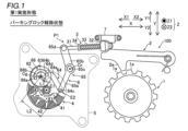
- FIG. 2 is a front view showing the parking lock release state of the vehicle parking device of the first embodiment.
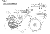
- FIG. 2 is a front view showing the parking lock state of the vehicle parking device of the first embodiment. It is a graph showing a change in the reduction ratio of the transmission mechanism when the driven gear of the vehicle parking device of the first embodiment rotates.
- FIG. 3 is a front view showing a state in which the engaging pawl of the park pole and the teeth of the park gear face each other in the parking lock released state of the vehicle parking device of the first embodiment.
- FIG. 3 is a front view showing a state in which the engaging pawl of the park pole presses the teeth of the park gear in the parking lock waiting state of the vehicle parking device of the first embodiment.
- FIG. 2 is a front view showing a case where an external force that moves a park rod is generated in a parking lock released state of the vehicle parking device of the first embodiment.
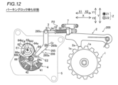
- FIG. 2 is a front view showing a case where an external force that moves a park rod is generated in the parking lock state of the vehicle parking device of the first embodiment.
- 7 is a graph showing a first regulation range and a second regulation range of changes in the reduction ratio of the transmission mechanism when the driven gear of the vehicle parking device of the first embodiment rotates.
- FIG. 7 is a front view showing the parking lock release state of the vehicle parking device according to the second embodiment.
- FIG. 7 is a front view showing the parking lock state of the vehicle parking device according to the second embodiment.
- FIG. 7 is a front view showing a state in which the engaging pawl of the park pole and the teeth of the park gear face each other in the parking lock released state of the vehicle parking device of the second embodiment.
- FIG. 7 is a front view showing a state in which the engaging pawl of the park pole presses the teeth of the park gear in the parking lock waiting state of the vehicle parking device of the second embodiment.
- the vehicle parking device 100 is mounted on a vehicle.
- a vehicle when an occupant (driver) performs a shift switching operation via a parking switch, electrical shift switching control is performed.
- a shift position switching signal is input to the vehicle parking device 100 via a sensor provided on the parking switch. Based on the signal input from the parking switch, the vehicle parking device 100 is switched to the P (parking) position and the non-P (non-parking) position corresponding to the switching operation by the occupant, and the vehicle parking device 100 also switches the vehicle parking device 100 to the P (parking) position and the non-P (non-parking) position. You can switch whether or not to lock the rotation.
- Shift switching control as described above is called shift-by-wire.
- a vehicle on which such shift switching control is performed is an electric vehicle that includes only a motor as a power source.
- the vehicle parking device 100 has a structure that can switch between locking and unlocking the rotation of the wheels.
- the vehicle parking device 100 includes a parking gear 1, a park pole 2, a park rod 3, a motor 4, a case 5, and a transmission mechanism 6.
- the direction in which the rotation center axis Cm of the motor 4 extends is defined as the Z direction, one side of the Z direction is defined as the Z1 direction, and the other side of the Z direction is defined as the Z2 direction.
- the direction in which the motor 4 and the parking gear 1 are lined up is defined as the X direction
- the motor 4 side in the X direction is defined as the X1 direction
- the parking gear 1 side in the X direction is defined as the X2 direction.
- the direction in which the parking gear 1 and the park pole 2 are lined up is the Y direction
- the park pole 2 side in the Y direction is the Y1 direction
- the parking gear 1 side in the Y direction is the Y2 direction.
- the X direction and the Y direction are perpendicular to each other.
- the Z direction is perpendicular to the X direction and the Y direction.
- the parking gear 1 is fixed to the wheels.
- the parking gear 1 is configured to rotate integrally with the wheels.
- the parking gear 1 is configured such that the locking claws 2a of the park pole 2 can mesh with the teeth 1a of the parking gear 1.
- the park pole 2 is rotated toward the parking gear 1 and guided to a position (lock position) where the locking pawl 2a and the teeth 1a of the parking gear 1 engage with each other.
- the parking pawl 2 is configured to stop the rotation of the parking gear 1 when the locking pawl 2a is guided to the lock position. In this manner, the locking pawl 2a of the park pole 2 is guided to the lock position, resulting in a parking lock state.
- the park pole 2 is rotated in a direction away from the teeth 1a of the parking gear 1 and guided to a position (unlock position) where the engagement between the locking pawl 2a and the teeth 1a of the parking gear 1 is released. .
- the locking pawl 2a of the park pole 2 is guided to the unlock position, thereby allowing the parking gear 1 to rotate. In this manner, the locking pawl 2a of the park pole 2 is guided to the unlock position, whereby the parking lock is released.
- the park rod 3 is configured to move along each of the X1 direction and the X2 direction.
- the park rod 3 is configured to move to a non-parking position P1 corresponding to a parking lock release state by moving in the X1 direction.
- the park rod 3 is configured to move to a parking position P2 corresponding to a parking lock state by moving in the X2 direction. That is, the parking rod 3 is configured to reciprocate between a parking position P2 corresponding to a parking locked state and a non-parking position P1 corresponding to a parking unlocked state. Since the park rod 3 is connected to the transmission mechanism 6, the park rod 3 is moved linearly by the driving force transmitted from the motor 4 via the transmission mechanism 6.
- the park rod 3 includes a rod portion 31, a cam portion 32, a retraction spring 33, and a support portion 34.
- the rod portion 31 is a rod-shaped member extending along the X direction.
- the cam portion 32 is fixed to the tip of the rod portion 31.
- the cam portion 32 is configured to reciprocate in a direction toward the park pole 2 (X2 direction) and a direction away from the park pole 2 (X1 direction) together with the reciprocation of the park rod 3.
- the park pole 2 is rotated by the cam surface of the cam part 32 so that the locking pawl 2a reaches the lock position.
- the cam surface of the cam part 32 rotates the park pole 2 so that the locking pawl 2a reaches the unlock position.
- the retraction spring 33 is, for example, a coil spring.
- One end of the retraction spring 33 on the X2 direction side is in contact with the X1 direction side of the cam portion 32 on the rod portion 31 .
- the other end of the retraction spring 33 on the X1 direction side is supported by the support section 34 by coming into contact with the X2 direction side of the support section 34 on the rod section 31 .
- the retraction spring 33 is configured to press the cam portion 32 against the guide portion 7 by pressing the cam portion 32 .
- the guide section 7 is configured to guide the cam section 32 moving in the X2 direction toward the Y2 direction side (park pole 2 side).
- the guide portion 7 faces the park pole 2 in the Y direction.
- the motor 4 is configured to generate a driving force for switching the vehicle between a parking lock state and a parking lock release state.
- the motor 4 is a three-phase surface permanent magnet motor (SPM) incorporating a permanent magnet.
- the motor 4 includes a stator 41, a rotor 42, and a motor shaft 43.
- the stator 41 includes a stator core and excitation coils of multiple phases (U phase, V phase, and W phase) that generate magnetic force when energized.
- the rotor 42 is rotated around a rotation center axis Cm extending in the Z direction.
- Motor shaft 43 is connected to rotor 42 .
- the motor shaft 43 is rotated together with the rotor 42 around a rotation center axis Cm extending in the Z direction.
- the case 5 is a member that houses the motor 4 in a fixed position.
- the case 5 rotatably supports a motor shaft 43 provided on the motor 4 which is in a fixed position.
- a rotation shaft 63 and an engagement pin 66a, which will be described later, are fixed to the case 5 in a fixed position.
- the rotation shaft 63 is an example of a "first rotation shaft” in the claims.
- the transmission mechanism 6 is configured to transmit the driving force of the motor 4 to the park rod 3.
- the input side of the transmission mechanism 6 is connected to the motor 4.
- the output side of the transmission mechanism 6 is connected to the park rod 3.
- the transmission mechanism 6 includes a driving gear 61, a driven gear 62, a rotation shaft 63, a link member 64, a connecting member 65, and a stopper 66.
- the drive gear 61 is configured to rotate around a rotation center axis Cm extending in the Z direction integrally with the motor shaft 43 by the driving force from the motor 4.
- the drive gear 61 is a pinion gear (small diameter gear) attached to the motor shaft 43.
- the driving gear 61 meshes with the driven gear 62.
- the driven gear 62 is configured to rotate around the rotation center axis Cg by the driving force from the motor 4.
- the driven gear 62 is a sector gear (sector gear) that is attached to the rotating shaft 63 and has a plurality of external teeth on a part of its outer periphery.
- Driven gear 62 is connected to motor 4 via drive gear 61 .
- a plurality of external teeth of the driven gear 62 mesh with external teeth of the drive gear 61.
- the number of teeth of the driven gear 62 is greater than the number of teeth of the drive gear 61.
- the rotational speed of the drive gear 61 is reduced at the driven gear 62. That is, the torque from the motor 4 is increased by being transmitted from the driving gear 61 to the driven gear 62.
- the rotation shaft 63 is arranged on the rotation center axis Cg of the driven gear 62.
- the rotation shaft 63 extends in the Z direction.
- a driven gear 62 is integrally and rotatably attached to the rotation shaft 63.
- the link member 64 can transmit torque from the driven gear 62 to the connecting member 65, and can also transmit torque from the connecting member 65 to the driven gear 62. That is, the link member 64 is a connecting member that connects the driven gear 62 and the connecting member 65.
- the link member 64 has a link main body portion 64a, a drive side pin 64b, an output side pin 64c, and a relief portion 64d.
- the link main body portion 64a is a J-shaped plate member when viewed from the Z1 direction side.
- the drive side pin 64b connects the drive side (input side) of the link body 64a and the driven gear 62.
- the drive-side pin 64b is connected to the drive-side end E1 of the link body 64a.
- the drive side end portion E1 is a portion of the link body portion 64a located closer to the rotation shaft 63 than the output side pin 64c.
- the drive side end E1 is a portion located around the rotation shaft 63.
- the drive side pin 64b is connected to a portion of the driven gear 62 on the rotation center axis Cg side.
- a portion of the driven gear 62 on the rotation center axis Cg side is a portion located around the rotation shaft 63.
- the drive-side end E1 of the link member 64 is one end of the link member 64 that rotates with the rotation of the driven gear 62 because it is connected to the driven gear 62 by the drive-side pin 64b.
- the output side pin 64c connects the output side of the link main body 64a and the connecting member 65.
- the output pin 64c is connected to the output end E2 of the link body 64a.
- the output side end portion E2 is a portion of the link main body portion 64a located further from the rotation shaft 63 than the drive side pin 64b.
- the output end E2 is a portion that does not overlap the driven gear 62 when viewed from the Z1 direction.
- the output pin 64c is connected to a portion of the connection member 65 on the Y2 direction side.
- the output side end E2 of the link member 64 is the other end of the link member 64 that rotates as the drive side end E1 rotates as the driven gear 62 rotates.
- the distance L1 between the rotational center axis Cg of the driven gear 62 and the drive side end E1 of the link member 64 when viewed from the Z1 direction is 62 and the output side end E2 of the link member 64.
- the distance L1 is the distance between the rotational center axis Cg of the driven gear 62 and the center point of the drive-side pin 64b when viewed from the Z1 direction side.
- the distance L2 is the distance between the rotation center axis Cg of the driven gear 62 and the center point of the output side pin 64c when viewed from the Z1 direction side.
- the relief portion 64d is curved to avoid interference with the rotating shaft 63.
- the relief portion 64d is a recessed portion in which a portion of the link body portion 64a on the driving side end E1 side is recessed on the side opposite to the rotational center axis Cm of the motor 4 with respect to the rotational center axis Cg of the driven gear 62. It is.
- the escape portion 64d serving as a recess prevents interference between the link member 64 and the rotating shaft 63 in the parking lock state.
- the relief portion 64d is configured to avoid interference with the rotating shaft 63 in the parking lock state while the link member 64 reciprocates between the parking lock state and the parking lock release state. That is, the relief portion 64d is curved to avoid interference with the rotating shaft 63 in the parking lock state while the link member 64 reciprocates between the parking lock state and the parking lock release state.
- the connecting member 65 connects the link member 64 and the park rod 3.
- the connection member 65 has a first link 65a, a second link 65b, an output shaft 65c, and a rod side pin 65d.
- the output shaft 65c is an example of a "second rotation shaft” in the claims.
- the first link 65a is a plate-like member that connects the link member 64 and the second link 65b.
- One end of the first link 65a on the Y2 direction side is connected to the link member 64. That is, one end of the first link 65a on the Y2 direction side and the link member 64 are connected by an output pin 64c.
- the other end of the first link 65a on the Y1 direction side is connected to the second link 65b. That is, the other end of the first link 65a in the Y1 direction and the second link 65b are connected by the output shaft 65c.
- the second link 65b is a plate-like member that connects the first link 65a and the park rod 3.
- One end of the second link 65b on the Y1 direction side is connected to the park rod 3. That is, one end of the second link 65b on the Y1 direction side and the park rod 3 are connected by a rod-side pin 65d.
- the other end of the second link 65b on the Y2 direction side is connected to the first link 65a. That is, the other end of the second link 65b on the Y2 direction side and the first link 65a are connected by the output shaft 65c.
- the first link 65a and the second link 65b are plate-like members having an L-shape when viewed from the Z1 direction side.
- the output shaft 65c is configured to output the torque transmitted from the motor 4 via the drive gear 61, driven gear 62, and link member 64 to the second link 65b connected to the park rod 3. That is, the output shaft 65c connects the other end of the first link 65a in the Y1 direction and the other end of the second link 65b in the Y2 direction.
- the output shaft 65c is a rotation center axis extending along the Z direction for rotating the first link 65a and the second link 65b by the torque from the motor 4.
- the output shaft 65c is a spline shaft in which a convex portion protruding in a direction perpendicular to the Z direction is formed.
- first link 65a and the second link 65b are engaged with each other in the circumferential direction around the central axis of the output shaft 65c by the output shaft 65c, which is a spline shaft.
- the first link 65a and the second link 65b are configured to rotate integrally around the rotation center axis Cr of the output shaft 65c.
- the stopper 66 is configured to stop further rotation of the driven gear 62 due to an external force applied to the park rod 3 in the parking lock released state. That is, the stopper 66 prevents the rotation of the driven gear 62 when the park rod 3 at the non-parking position P1 further moves (retreats) in the X1 direction due to an external force applied to the park rod 3 in the parking lock released state. It is configured to stop.
- the stopper 66 is configured to stop further rotation of the driven gear 62 due to an external force applied to the park rod 3 in the parking lock state. That is, the stopper 66 is configured to stop the rotation of the driven gear 62 when the park rod 3 at the parking position P2 further moves (forward) in the X2 direction due to an external force applied to the park rod 3 in the parking lock state. It is composed of
- the stopper 66 has an engagement pin 66a and a slit 66b.
- the engagement pin 66a extends from the case 5 in the Z1 direction.
- the end of the engagement pin 66a on the Z2 direction side is fixed to the case 5. Thereby, the arrangement position of the engagement pin 66a is fixed.
- the engagement pin 66a is slidably inserted into the slit 66b.
- the slit 66b is formed to penetrate the driven gear 62 in the Z2 direction.
- the slit 66b is formed in an arc shape along the circumferential direction around the rotation center axis Cg of the driven gear 62.
- the rotation center angle of the slit 66b is, for example, about 180 degrees.
- the slit 66b rotates as the driven gear 62 rotates.
- the transmission mechanism 6 has a function as a speed reduction mechanism that increases the torque of the motor 4 and transmits it to the park rod 3 via the output shaft 65c. That is, by laying out the transmission mechanism 6 as shown in FIGS. 1 and 2, the reduction ratio of the transmission mechanism 6 changes as shown in FIG. 3. In FIG. 3, the reduction ratio of the transmission mechanism 6 is shown in correspondence with the change in the rotation angle of the driven gear 62. The reduction ratio of the transmission mechanism 6 is based on the ratio between the number of teeth of the driving gear 61 and the number of teeth of the driven gear 62, and the ratio of the rotation angle of the rotation shaft 63 and the rotation angle of the output shaft 65c. is obtained based on multiplication with the reduction ratio based on
- the layout of the transmission mechanism 6 refers to the drive gear 61, driven gear 62, rotation shaft 63, link member 64, connection member 65, and stopper 66 when the transmission mechanism 6 is viewed from the Z1 direction side. The arrangement and dimensions of each are shown. Specifically, the layout of the transmission mechanism 6 is determined by the length of the link member 64, the arrangement position of the link member 64, the connection position between the link member 64 and the driven gear 62, and the connection between the link member 64 and the first link 65a.
- the transmission mechanism 6 can change the reduction ratio of the transmission mechanism 6 from the maximum reduction ratio while switching the parking lock release state of the vehicle to either the parking lock state or the parking lock waiting state. It functions as a speed reduction mechanism that reduces speed so that the speed reduction ratio of the transmission mechanism 6 decreases toward the minimum speed reduction ratio and increases from the minimum speed reduction ratio to the maximum speed reduction ratio. That is, in the transmission mechanism 6, while the parking rod 3 reaches the parking position P2 from the non-parking position P1, the reduction ratio of the transmission mechanism 6 decreases from the maximum reduction ratio to the minimum reduction ratio. It functions as a speed reduction mechanism that reduces the speed so that the speed reduction ratio increases from the minimum speed reduction ratio to the maximum speed reduction ratio.
- the vehicle parking device 100 has a structure in which the link member 64 does not move due to external force applied to the park rod 3 in both the parking lock state and the parking lock release state.
- the parking rod 3 in the non-parking position P1 as shown in FIG. 1 may be unintentionally moved to the parking position P2 due to external force caused by vehicle vibration or the like.
- the vehicle may be braked unintentionally.
- the park rod 3 at the parking position P2 as shown in FIG. 2 may be unintentionally moved to the non-parking position P1 due to external force caused by vibrations of the vehicle or the like.
- the stopped vehicle may move unintentionally.
- the locking claw 2a of the park pole 2 and the groove between the teeth 1a of the parking gear 1 do not face each other, and the locking claw 2a of the park pole 2 and the groove between the teeth 1a of the parking gear 1 do not face each other.
- the teeth 1a of the gear 1 are opposed to each other, not only an external force caused by vibrations of the vehicle but also an external force caused by the retraction spring 33 is applied to the park rod 3. Therefore, in this case, unintended movement of the park rod 3 is more likely to occur.
- the reaction force applied to the support portion 34 in the X1 direction is an external force that moves the park rod 3 from the parking position P2 to the non-parking position P1.
- an external force due to vehicle vibration etc. but also an external force due to the retraction spring 33 is applied to the park rod 3. It will be done.
- the link member 64 is configured to be in the consideration point state in both the parking lock state and the parking lock release state. ing.
- the link member 64 when the link member 64 is in the state of consideration, it means that even if the above-mentioned external force is applied to the park rod 3, the link member 64 (the link member 64 does not move) does not generate torque for moving the link member 64. (no) condition.
- the link member 64 in the consideration point state prevents the park rod 3 at the parking position P2 from unintentionally moving to the non-parking position P1.
- the link member 64 in the consideration point state prevents the parking rod 3 from the non-parking position P1 from unintentionally moving to the parking position P2. In this manner, in the vehicle parking device 100, unintended movement of the parking rod 3 is suppressed mechanically and structurally without using the driving force of the motor 4.
- the rotation center axis Cg of the driven gear 62, the drive side end E1 of the link member 64, and the output side end E2 of the link member 64 are in both the parking lock state and the parking lock release state. , they are arranged in a straight line when viewed from the Z1 direction side (one side in the direction in which the rotation center axis Cg of the driven gear 62 extends).
- the center point of the drive side pin 64b of the arranged link member 64 and the center point of the output side pin 64c of the link member 64 are arranged on the straight line La.
- the rotation center axis Cg of the rotation shaft 63 of the driven gear 62 lies on the straight line La connecting the center point of the drive side pin 64b of the link member 64 and the center point of the drive side pin 64b of the link member 64.
- the rotational center of the driven gear 62 is an axis Cg
- a drive side end E1 of the link member 64 located on the opposite side from the output side end E2 with respect to the rotation center axis Cg of the driven gear 62, and an output side end E2 of the link member 64. are lined up in a straight line.
- the rotation center axis Cg of the rotation shaft 63 of the driven gear 62 and the rotation center axis Cg of the driven gear 62 are arranged on the X1 direction side.
- the center point of the drive side pin 64b of the link member 64 and the center point of the output side pin 64c of the link member 64 are arranged on the straight line La.
- the rotation center axis Cg of the rotation shaft 63 of the driven gear 62 lies on the straight line La connecting the center point of the drive side pin 64b of the link member 64 and the center point of the drive side pin 64b of the link member 64.
- the link member 64 becomes the second consideration point.
- the relief portion 64d is configured to avoid interference with the rotation shaft 63.
- the driven gear 62 is prevented from further rotation by the stopper 66, and the drive side end E1 and the output side end are The rotation of the driven gear 62 (indicated by a two-dot chain line in FIG. 6) that returns the park rod 3 to the parking position P2 is stopped by the link member 64 in which the portion E2 is arranged in a straight line. That is, the stopper 66 prevents the driven gear 62 from rotating in the Ri1 direction, where the rotation angle of the driven gear 62 is from the first rotation angle Deg1 to 0 degrees. In this way, the stopper 66 sets the lower limit of the first regulation range Re1.
- the driven gear 62 is prevented from further rotation by the stopper 66, and the drive side end E1 and the output side end are The rotation of the driven gear 62 that returns the parking rod 3 to the non-parking position P1 (indicated by a two-dot chain line in FIG. 7) is stopped by the link member 64 in which E2 is arranged in a straight line. That is, the stopper 66 prevents the driven gear 62 from rotating in the Ri2 direction, where the rotation angle of the driven gear 62 increases from the second rotation angle Deg2. In this way, the upper limit of the second regulation range Re2 is set by the stopper 66.
- the link member 64 has a relief portion 64d that avoids interference with the rotating shaft 63 while the link member 64 reciprocates between the parking lock state and the parking lock release state. have.
- the link member 64 is placed in a position where interference with the rotating shaft 63 is avoided by the relief portion 64d, so that the external force is reduced. Even if the park rod 3 attempts to move, the link member 64 can block the torque generated due to external force.
- the link member 64 by arranging the link member 64 at a position that avoids interference with the rotation shaft 63 in the parking lock release state during reciprocating between the parking lock state and the parking lock release state, the external force is applied to the park rod 3.
- the link member 64 can block the torque generated due to external force. As a result, it is possible to realize a structure in which the link member 64 is difficult to move even if an external force is applied to the parking rod 3 in both the parking lock state and the parking lock release state. Further, when the link member 64 reciprocates with the rotation of the driven gear 62 to switch between the parking lock release state and the parking lock release state, the driven gear 62 and the link member 64 interfere with each other due to the relief portion 64d. You can prevent it from happening.
- the relief portion 64d is curved to avoid interference with the rotating shaft while the link member 64 reciprocates between the parking lock state and the parking lock release state.
- the structure of the relief portion 64d that avoids interference between the driven gear 62 and the link member 64 can be realized with a simple structure, so that the structure of the link member 64 can be prevented from becoming complicated.
- the rotation center axis Cg of the driven gear 62, the drive side end E1 of the link member 64, and the output side end E2 of the link member 64 are In this state, they are lined up in a straight line when viewed from the Z1 direction side (one side in the direction in which the rotation center axis Cg of the driven gear 62 extends).
- the link member 64, in which the drive side end E1 and the output side end E2 are lined up in a straight line with respect to the rotation center axis Cg of the driven gear 62 is in a state where no torque is transmitted.
- the link member 64 does not move even if an external force is applied to the park rod 3, which is the important point in the link mechanism. It is not necessary to provide a sensor and drive the motor 4 based on the detection signal of this sensor so that the driven gear 62 does not move. As a result, in the parking lock state, there is no need to supply power to the sensor and motor 4, so power consumption of the vehicle parking device 100 can be suppressed.
- the rotation center axis Cg of the driven gear 62 when viewed from the Z1 direction side (one side in the direction in which the rotation center axis Cg of the driven gear 62 extends), the rotation center axis Cg of the driven gear 62, The drive side end E1 of the link member 64, which is disposed on the opposite side of the output side end E2 with respect to the rotation center axis Cg of the driven gear 62, and the output side end E2 of the link member 64 are in a straight line. They are lined up in a shape. As a result, in the parking lock state, the driving side end E1 of the link member 64 is moved to the output side end E2 side with respect to the rotation center axis Cg of the driven gear 62, opposite to the output side end E2.
- the rotation center axis Cg of the driven gear 62, the drive side end E1 of the link member 64, and the output side end E2 of the link member 64 are In the released state, they are lined up in a straight line when viewed from the Z1 direction side (one side in the direction in which the rotation center axis Cg of the driven gear 62 extends).
- the link member 64, in which the driving side end E1 and the output side end E2 are lined up in a straight line with respect to the rotation center axis Cg of the driven gear 62 does not transmit torque.
- the rotation center axis Cg of the driven gear 62 when viewed from the Z1 direction side (one side in the direction in which the rotation center axis Cg of the driven gear 62 extends), the rotation center axis Cg of the driven gear 62, The drive side end E1 of the link member 64, which is disposed on the output side end E2 side with respect to the rotation center axis Cg of the driven gear 62, and the output side end E2 of the link member 64 are aligned in a straight line. I'm here.
- the drive side end E1 of the link member 64 on the output side end E2 side with respect to the rotation center axis Cg of the driven gear 62, external force is applied to the park rod 3.
- the transmission mechanism 6 stops further rotation of the driven gear 62 due to the external force applied to the parking rod 3 in the parking lock release state, and in the parking lock state, It includes a stopper 66 that stops further rotation of the driven gear 62 due to an external force applied to the park rod 3.
- the driven gear 62 is prevented from further rotation by the stopper 66, and the driving side end E1 and the output side end E2 are linearly formed with respect to the rotation center axis Cg of the driven gear 62.
- the rotation of the driven gear 62 returning to the parking position P2 is stopped by the link members 64 arranged in the same manner.
- the driven gear 62 is prevented from further rotation by the stopper 66, and the drive side end E1 and the output side end E2 are aligned in a straight line with respect to the rotation center axis Cg of the driven gear 62.
- the link members 64 arranged in a row prevent the driven gear 62 from rotating back to the non-parking position P1.
- the driven gear 62 is further rotated by the stopper 66, and the driven gear 62 is moved to another shift position (parking position P2 or non-parking position P1) due to the structure in which the stopper 66 causes further rotation of the driven gear 62, and the link member 64 is in a state where it does not move.
- the rotation of the driven gear 62 returning to is stopped.
- the rotation angle at which the stopper 66 stops the rotation of the driven gear 62 and the structure in which the link member 64 is in a state of consideration in the link mechanism in which it does not move the driven gear
- the rotation of the driven gear 62 can be stopped within a range between the rotation angle at which the rotation of the driven gear 62 is stopped. As a result, it is possible to realize a structure that more reliably stops rotation of the driven gear 62 in each of the parking lock state and the parking lock release state.
- the transmission mechanism 6 includes the connection member 65 that connects the link member 64 and the park rod 3.
- the connection member 65 has an output shaft 65c located at the rotation center of the connection member 65.
- the connecting member 65 is configured to rotate around a rotation center axis Cr passing through the rotation center of the output shaft 65c.
- the connecting member 65 can be rotated around the output shaft 65c by reciprocating the link member 64 between the parking lock state and the parking lock release state, so that the park rod 3 can be moved between the parking position P2 and the non-parking position. It is possible to make a round trip to P1.
- the vehicle parking device 200 includes a lever portion 265a. Note that in the second embodiment, detailed explanations of the same configurations as in the first embodiment will be omitted.
- the vehicle parking device 200 includes a parking gear 1, a park pole 2, a park rod 3, a motor 4, a case 5, and a transmission mechanism 206.
- the direction in which the rotation center axis Cm of the motor 4 extends is defined as the Z direction, one side of the Z direction is defined as the Z1 direction, and the other side of the Z direction is defined as the Z2 direction.
- the direction in which the motor 4 and the parking gear 1 are lined up is defined as the X direction
- the motor 4 side in the X direction is defined as the X1 direction
- the parking gear 1 side in the X direction is defined as the X2 direction.
- the direction in which the parking gear 1 and the park pole 2 are lined up is the Y direction
- the park pole 2 side in the Y direction is the Y1 direction
- the parking gear 1 side in the Y direction is the Y2 direction.
- the X direction and the Y direction are perpendicular to each other.
- the Z direction is perpendicular to the X direction and the Y direction.
- the transmission mechanism 6 is configured to transmit the driving force of the motor 4 to the park rod 3.
- the input side of the transmission mechanism 6 is connected to the motor 4.
- the output side of the transmission mechanism 6 is connected to the park rod 3.
- the transmission mechanism 6 includes a driving gear 61, a driven gear 62, a rotation shaft 63, a link member 64, a connecting member 265, and a stopper 66.
- the rotation shaft 63 is an example of a "first rotation shaft” in the claims.
- the connecting member 265 connects the link member 64 and the park rod 3.
- the connecting member 265 has a lever portion 265a, a rotation shaft 265b, and a rod side pin 265c.
- the rotation axis 265b is an example of a "second rotation axis" in the claims.
- the lever portion 265a is an L-shaped plate member that connects the link member 64 and the park rod 3.
- One end of the lever portion 265a on the Y2 direction side is connected to the link member 64. That is, one end of the lever portion 265a on the Y2 direction side and the link member 64 are connected by the output side pin 64c.
- the other end of the lever portion 265a on the Y1 direction side is connected to the park rod 3. That is, the other end of the lever portion 265a in the Y1 direction and the park rod 3 are connected by a rod-side pin 265c.
- the rotation shaft 265b is a rotation center axis extending along the Z direction for rotating the lever portion 265a by the torque from the motor 4.
- the rotation shaft 265b is arranged at the center of rotation of the lever portion 265a.
- the lever portion 265a is configured to rotate around a rotation center axis Cr passing through the rotation center of the rotation shaft 265b.
- the rod side pin 265c is configured to output torque transmitted from the motor 4 to the park rod 3 via the drive gear 61, driven gear 62, link member 64, and lever portion 265a. That is, the rod side pin 265c connects the other end of the lever portion 265a on the Y1 direction side and one end of the park rod 3 on the X1 direction side.
- the vehicle parking device 200 has a structure in which the link member 64 does not move due to external force applied to the park rod 3 in both the parking lock state and the parking lock release state.
- the parking rod 3 at the non-parking position P1 as shown in FIG. there are cases where the user is unintentionally moved to position P2. Further, the parking rod 3 at the parking position P2 as shown in FIG. 10 may be unintentionally moved to the non-parking position P1 due to external force caused by vibrations of the vehicle or the like.
- the parking rod 3 when the parking rod 3 is in the parking position P2 as shown in FIGS. 11 and 12, the locking pawl 2a of the parking pole 2 and the groove between the teeth 1a of the parking gear 1 do not face each other, and the parking rod 3 is in the parking position P2 as shown in FIGS.
- the vehicle parking device 200 of the second embodiment is configured such that the link member 64 is in the consideration point state in both the parking lock state and the parking lock release state. ing. Specifically, the rotation center axis Cg of the driven gear 62, the drive side end E1 of the link member 64, and the output side end E2 of the link member 64 are in both the parking lock state and the parking lock release state. , they are arranged in a straight line when viewed from the Z1 direction side (one side in the direction in which the rotation center axis Cg of the driven gear 62 extends). Note that the other configurations of the second embodiment are similar to those of the first embodiment.
- the link member 64 is provided with an escape mechanism to avoid interference with the rotating shaft 63 while the link member 64 reciprocates between the parking lock state and the parking lock release state. It has a section 64d. Thereby, it is possible to realize a structure in which the link member 64 is difficult to move even if an external force is applied to the parking rod 3 in both the parking lock state and the parking lock release state.
- the transmission mechanism 206 includes the connection member 265 that connects the link member 64 and the park rod 3.
- the connection member 265 has a rotation shaft 265b located at the rotation center of the connection member 265.
- the connecting member 65 is configured to rotate around a rotation center axis Cr passing through the rotation center of the rotation shaft 265b.
- the connecting member 265 can be rotated around the rotation axis 265b by reciprocating the link member 64 between the parking lock state and the parking lock release state, so that the park rod 3 can be moved between the parking position P2 and the non-parking position. It is possible to reciprocate to and from position P1.
- the other effects of the second embodiment are the same as those of the first embodiment, so description thereof will be omitted.
- the vehicle is an electric vehicle, but the present invention is not limited to this.
- the vehicle may be a hybrid vehicle including an engine and a motor.
- the vehicle parking device 100 includes a parking gear 1, a park pole 2, a park rod 3, a motor 4, a case 5, and a transmission mechanism 6.
- the vehicle parking device includes a parking gear, a park pole, a park rod, a motor, a case, a transmission mechanism, a detent spring, and a groove that corresponds to each of a parking position and a non-parking position. It may also be provided with a detent plate.
- the link main body portion 64a is a J-shaped plate member with the curved relief portion 64d when viewed from the Z1 direction side, but the present invention is not limited to this. Not limited.
- the link main body portion may be a plate member having an L-shape with a bent relief portion when viewed from one side in the direction in which the rotation center axis of the driven gear extends.
- This embodiment includes at least the following configurations.
- the vehicle parking device 100 (200) is connected to a motor (4) that generates a driving force for switching between a parking lock state and a parking lock release state of the vehicle, and a motor (4) that generates a driving force for switching between a parking lock state and a parking unlock state of the vehicle.
- the transmission mechanism 6 (206) is connected to the transmission mechanism 6 (206) and reciprocates between the parking position (P2) corresponding to the parking lock state and the non-parking position (P1) corresponding to the parking lock release state.
- the transmission mechanism 6 (206) includes a driven gear (62) that rotates around the rotation center axis (Cg) by the driving force from the motor (4), and a driven gear (62) and rotates with the rotation of the driven gear (62), and the output side which is the other end that rotates with the rotation of the drive side end (E1).
- the link member (64) includes a link member (64) having an end portion (E2) and a first rotation shaft (63) disposed on the rotation center axis (Cg) of the driven gear (62). ) has a relief portion (64d) that avoids interference with the first rotation shaft (63) while the link member (64) reciprocates between the parking lock state and the parking lock release state.
- the link in the parking lock state while reciprocating between the parking lock state and the parking lock release state, the link is positioned at a position where interference with the first rotating shaft (63) is avoided by the relief portion (64d).
- the link member (64) can block the torque generated due to the external force.
- the link member (64) is arranged at a position that avoids interference with the first rotation shaft (63) in the parking lock release state while reciprocating between the parking lock state and the parking lock release state. Even if the park rod (3) attempts to move due to an external force, the link member (64) can block the torque generated due to the external force.
- the link member (64) is difficult to move even if an external force is applied to the park rod (3) in both the parking lock state and the parking lock release state. Further, when the link member (64) reciprocates with the rotation of the driven gear (62) to switch between the parking lock release state and the parking lock release state, the relief portion (64d) causes the driven gear (62) to move back and forth. ) and the link member (64) can be prevented from interfering with each other.
- the relief portion (64d) is bent or curved to avoid interference with the rotating shaft while the link member (64) reciprocates between the parking lock state and the parking lock release state.
- the structure of the relief part (64d) that avoids interference between the driven gear (62) and the link member (64) can be realized with a simple structure, so that It is possible to suppress the complexity of the structure.
- the rotation center axis (Cg) of the driven gear (62), the drive side end (E1) of the link member (64), and the output side end (E2) of the link member (64) are in the parking lock state. , they are arranged in a straight line when viewed from one side in the direction in which the rotation center axis (Cg) of the driven gear (62) extends.
- the drive side end (E1) and the output side end (E2) are aligned in a straight line with respect to the rotation center axis (Cg) of the driven gear (62). Since the link member (64) is in a state where no torque is transmitted, even if the park rod (3) attempts to move due to an external force, the torque generated due to the external force is blocked by the link member (64) at the thoughtful point. be done. As a result, in the parking lock state, the link member (64) does not move even if an external force is applied to the park rod (3), which is a critical point in the link mechanism.
- a drive side end (E1) of the link member (64) located on the opposite side of the output side end (E2) with respect to the axis (Cg), and an output side end (E2) of the link member (64). are lined up in a straight line.
- the drive side end (E1) of the link member (64) is aligned with the output side end (E2) with respect to the rotation center axis (Cg) of the driven gear (62).
- a structure is created in which the link member (64) does not move even if an external force is applied to the park rod (3). It can be realized.
- it is possible to suppress an increase in the amount of movement of the link member (64) in order to realize a structure in which the link member (64) is in a state of consideration in a link mechanism in which it does not move.
- the rotation center axis (Cg) of the driven gear (62), the drive side end (E1) of the link member (64), and the output side end (E2) of the link member (64) are connected to each other when the parking lock is released. In this state, they are arranged in a straight line when viewed from one side in the direction in which the rotation center axis (Cg) of the driven gear (62) extends.
- the drive side end (E1) and the output side end (E2) are aligned in a straight line with respect to the rotation center axis (Cg) of the driven gear (62). Since the link member (64) is in a state where it does not transmit torque, even if the park rod (3) tries to move due to an external force, the torque generated due to the external force is transferred by the link member (64) at the point where it is not transmitted. will be cut off. As a result, in the parking lock released state, the link member (64) does not move even if an external force is applied to the park rod (3), which is a critical point in the link mechanism.
- the drive side end (E1) of the link member (64) is aligned with the output side end (E2) with respect to the rotation center axis (Cg) of the driven gear (62). ) side, it is possible to realize a structure in which the link member (64) is in a state where it does not move even if an external force is applied to the park rod (3). As a result, it is possible to suppress an increase in the amount of movement of the link member (64) in order to realize a structure in which the link member (64) is in a state of consideration in a link mechanism in which it does not move.
- the transmission mechanism 6 (206) stops further rotation of the driven gear (62) due to external force applied to the park rod (3) in the parking lock released state, and also prevents the driven gear (62) from rotating further due to the external force applied to the park rod (3) in the parking lock state.
- the drive gear (62) further includes a stopper (66) for stopping further rotation of the driven gear (62) due to the applied external force, and the further rotation of the driven gear (62) is stopped by the stopper (66) when the parking lock is released.
- the parking position When the rotation of the driven gear (62) returning to P2) is stopped, and in the parking lock state, further rotation is stopped by the stopper (66), and the center axis of rotation of the driven gear (62) is stopped.
- the rotation of the driven gear (62) to return to the non-parking position (P1) is performed by the link member (64) in which the drive side end (E1) and the output side end (E2) are arranged in a straight line with respect to (Cg). Movement is stopped.
- the stopper (66) prevents further rotation of the driven gear (62), and the structure in which the link member (64) remains stationary allows the driven gear (62) to rotate further. Rotation of the driven gear (62) returning to the shift position (parking position (P2) or non-parking position (P1)) is stopped. As a result, in each of the parking lock state and the parking lock release state, the rotation angle at which the driven gear (62) is stopped by the stopper (66) and the state of consideration in the link mechanism in which the link member (64) does not move are determined. With this structure, the rotation of the driven gear (62) can be stopped within a range between the rotation angle at which the rotation of the driven gear (62) is stopped. As a result, it is possible to realize a structure that more reliably stops rotation of the driven gear (62) in each of the parking lock state and the parking lock release state.
- the transmission mechanism 6 (206) further includes a connection member 65 (265) that connects the link member (64) and the park rod (3), and the connection member 65 (265) is configured to rotate the connection member 65 (265).
- the connecting member 65 (265) has a second rotation shaft 65c (265b) arranged at the center position, and the connection member 65 (265) has a rotation center axis (Cr) passing through the rotation center of the second rotation shaft 65c (265b). It is configured to rotate around the
- the connecting member 65 (265) can be rotated around the second rotation axis 65c (265b) by reciprocating the link member (64) between the parking lock state and the parking lock release state. Therefore, the park rod (3) can be moved back and forth between the parking position (P2) and the non-parking position (P1).
Landscapes
- Engineering & Computer Science (AREA)
- General Engineering & Computer Science (AREA)
- Mechanical Engineering (AREA)
- Transportation (AREA)
- Gear-Shifting Mechanisms (AREA)
Abstract
Description
上記目的を達成するために、この発明の他の局面における車両用パーキング装置は、車両のパーキングロック状態およびパーキングロック解除状態を切り替えるための駆動力を発生させるモータと、モータに接続され、モータの駆動力を伝達する伝達機構と、伝達機構に接続され、パーキングロック状態に対応するパーキング位置と、パーキングロック解除状態に対応する非パーキング位置とを往復するパークロッドとを備え、伝達機構は、モータからの駆動力により回動中心軸線回りに回動する被駆動ギヤと、被駆動ギヤに接続され、被駆動ギヤの回動とともに回動する駆動側端部と、駆動側端部の回動とともに回動する他端部である出力側端部とを有するリンク部材とを含み、被駆動ギヤの回動中心軸線と、リンク部材の駆動側端部と、リンク部材の出力側端部とは、パーキングロック状態およびパーキングロック解除状態の両方において、被駆動ギヤの回動中心軸線の延びる方向の一方側から見て、直線状に並んでいる。
上記他の局面による車両用パーキング装置において、好ましくは、パーキングロック状態において、被駆動ギヤの回動中心軸線の延びる方向の一方側から見て、被駆動ギヤの回動中心軸線と、被駆動ギヤの回動中心軸線に対して出力側端部とは逆側に配置されたリンク部材の駆動側端部と、リンク部材の出力側端部とが、直線状に並んでおり、パーキングロック解除状態において、被駆動ギヤの回動中心軸線の延びる方向の一方側から見て、被駆動ギヤの回動中心軸線と、被駆動ギヤの回動中心軸線に対して出力側端部側に配置されたリンク部材の駆動側端部と、リンク部材の出力側端部とが、直線状に並んでいる。
上記他の局面による車両用パーキング装置において、好ましくは、伝達機構は、パーキングロック解除状態において、パークロッドに加えられた外力による被駆動ギヤのさらなる回動を止めるとともに、パーキングロック状態において、パークロッドに加えられた外力による被駆動ギヤのさらなる回動を止めるストッパをさらに含み、被駆動ギヤは、パーキングロック解除状態において、ストッパによりさらなる回動が止められるとともに、被駆動ギヤの回動中心軸線に対して駆動側端部および出力側端部を直線状に並べたリンク部材により、パーキング位置に戻す被駆動ギヤの回動が止められており、かつ、パーキングロック状態において、ストッパによりさらなる回動が止められるとともに、被駆動ギヤの回動中心軸線に対して駆動側端部および出力側端部を直線状に並べたリンク部材により、非パーキング位置に戻す被駆動ギヤの回動が止められている。
上記他の局面による車両用パーキング装置において、好ましくは、伝達機構は、被駆動ギヤの回動中心軸線上に配置された回動軸をさらに含み、リンク部材は、回動軸との干渉を避けるように屈曲または湾曲した逃げ部を有する。
上記他の局面による車両用パーキング装置において、好ましくは、伝達機構は、リンク部材とパークロッドとを接続する接続部材をさらに含み、接続部材は、リンク部材に一端部が接続される第1リンクと、パークロッドに一端部が接続される第2リンクと、第1リンクの他端部と第2リンクの他端部とを連結する出力軸とを有し、第1リンクおよび第2リンクは、出力軸の回動中心軸線回りを一体的に回動するように構成されている。
上記他の局面による車両用パーキング装置において、好ましくは、伝達機構は、リンク部材とパークロッドとを接続する接続部材をさらに含み、接続部材は、リンク部材に一端部が接続されるとともに、パークロッドに他端部が接続されるレバー部と、レバー部の回動中心の位置に配置された回動軸とを有し、レバー部は、回動軸の回動中心を通る回動中心軸線回りを回動するように構成されている。
上記他の局面による車両用パーキング装置において、パーキングロック状態およびパーキングロック解除状態の両方において、被駆動ギヤの回動中心軸線とリンク部材の駆動側端部との距離は、被駆動ギヤの回動中心軸線とリンク部材の出力側端部との距離よりも小さい。
上記他の局面による車両用パーキング装置において、リンク部材の駆動側端部は、被駆動ギヤの回動中心軸線の延びる方向の一方側から見て、被駆動ギヤの回動中心軸線に対して、出力側端部とは逆側および出力側端部側の各々に配置されることにより、パーキングロック状態およびパーキングロック解除状態の両方において、被駆動ギヤの回動中心軸線と出力側端部と直線状に並んでいる。
上記他の局面による車両用パーキング装置において、伝達機構は、パーキング位置から非パーキング位置にパークロッドが到達する間に、伝達機構の減速比が最大減速比から最小減速比に向かって減少するとともに、伝達機構の減速比が最小減速比から最大減速比に増加するように減速させる減速機構である。
図1~図8を参照して、第1実施形態による車両用パーキング装置100の構成について説明する。
図1および図2に示すように、伝達機構6は、モータ4の駆動力をパークロッド3に伝達するように構成されている。伝達機構6の入力側は、モータ4に接続されている。伝達機構6の出力側は、パークロッド3に接続されている。
ストッパ66は、パーキングロック解除状態において、パークロッド3に加えられた外力による被駆動ギヤ62のさらなる回動を止めるように構成されている。すなわち、ストッパ66は、パーキングロック解除状態において、パークロッド3に加えられた外力により、非パーキング位置P1のパークロッド3がさらにX1方向へ移動(後退)した場合の被駆動ギヤ62の回動を止めるように構成されている。
伝達機構6は、モータ4のトルクを増加させて出力軸65cを介してパークロッド3に伝達する減速機構としての機能を有している。すなわち、伝達機構6を図1および図2に示すようなレイアウトにすることにより、伝達機構6の減速比が図3に示すように変化する。図3では、被駆動ギヤ62の回動角度の変化に対応させて伝達機構6の減速比が示されている。伝達機構6の減速比は、駆動ギヤ61の歯数と被駆動ギヤ62の歯数との割合に基づく減速比と、回動軸63の回動角度と出力軸65cの回動角度との割合に基づく減速比との乗算に基づいて取得される。
また、車両用パーキング装置100では、パーキングロック状態およびパーキングロック解除状態の両方において、パークロッド3に加えられた外力によりリンク部材64が動かない構造が実現されている。
ここで、図6および図8に示すように、被駆動ギヤ62の回動角度がパークロッド3が非パーキング位置P1に移動した状態の第1回動角度Deg1である場合、ストッパ66および第1思案点のリンク部材64により、被駆動ギヤ62の回動が第1規制範囲Re1(図8において右斜めのハッチングにより表示)に規制されている。
第1実施形態では、以下のような効果を得ることができる。
図9~図12を参照して、第2実施形態による車両用パーキング装置200の構成について説明する。第2実施形態では、車両用パーキング装置200は、レバー部265aを備えている。なお、第2実施形態では、第1実施形態と同じ構成については、詳細な説明を省略する。
図9および図10に示すように、伝達機構6は、モータ4の駆動力をパークロッド3に伝達するように構成されている。伝達機構6の入力側は、モータ4に接続されている。伝達機構6の出力側は、パークロッド3に接続されている。
また、車両用パーキング装置200では、パーキングロック状態およびパーキングロック解除状態の両方において、パークロッド3に加えられた外力によりリンク部材64が動かない構造が実現されている。
第2実施形態では、以下のような効果を得ることができる。
今回開示された上記実施形態は、全ての点で例示であり制限的なものではないと考えられるべきである。本発明の範囲は上記実施形態の説明ではなく請求の範囲によって示され、さらに請求の範囲と均等の意味および範囲内での全ての変更(変形例)が含まれる。
本実施形態は、少なくとも以下の構成を備える。
4 モータ
6、206 伝達機構
62 被駆動ギヤ
63 回動軸(第1回動軸)
64 リンク部材
64d 逃げ部
65、265 接続部材
65c 出力軸(第2回動軸)
66 ストッパ
100、200 車両用パーキング装置
265b 回動軸(第2回動軸)
Cg (被駆動ギヤの)回動中心軸線
Cr (出力軸の)回動中心軸線
E1 駆動側端部
E2 出力側端部
P1 非パーキング位置
P2 パーキング位置
Claims (8)
- 車両のパーキングロック状態およびパーキングロック解除状態を切り替えるための駆動力を発生させるモータと、
前記モータに接続され、前記モータの駆動力を伝達する伝達機構と、
前記伝達機構に接続され、前記パーキングロック状態に対応するパーキング位置と、前記パーキングロック解除状態に対応する非パーキング位置とを往復するパークロッドとを備え、
前記伝達機構は、
前記モータからの駆動力により回動中心軸線回りに回動する被駆動ギヤと、
前記被駆動ギヤに接続され、前記被駆動ギヤの回動とともに回動する駆動側端部と、前記駆動側端部の回動とともに回動する他端部である出力側端部とを有するリンク部材と、
前記被駆動ギヤの前記回動中心軸線上に配置された第1回動軸とを含み、
前記リンク部材は、前記リンク部材が前記パーキングロック状態と前記パーキングロック解除状態とを往復する間に、前記第1回動軸との干渉を避けるような逃げ部を有する、車両用パーキング装置。 - 前記逃げ部は、前記リンク部材が前記パーキングロック状態と前記パーキングロック解除状態とを往復する間に、前記第1回動軸と干渉を避けるように屈曲または湾曲している、請求項1に記載の車両用パーキング装置。
- 前記被駆動ギヤの前記回動中心軸線と、前記リンク部材の前記駆動側端部と、前記リンク部材の前記出力側端部とは、前記パーキングロック状態において、前記被駆動ギヤの前記回動中心軸線の延びる方向の一方側から見て、直線状に並んでいる、請求項1に記載の車両用パーキング装置。
- 前記被駆動ギヤの前記回動中心軸線の延びる方向の一方側から見て、前記被駆動ギヤの前記回動中心軸線と、前記被駆動ギヤの前記回動中心軸線に対して前記出力側端部とは逆側に配置された前記リンク部材の前記駆動側端部と、前記リンク部材の前記出力側端部とが、直線状に並んでいる、請求項3に記載の車両用パーキング装置。
- 前記被駆動ギヤの前記回動中心軸線と、前記リンク部材の前記駆動側端部と、前記リンク部材の前記出力側端部とは、前記パーキングロック解除状態において、前記被駆動ギヤの前記回動中心軸線の延びる方向の一方側から見て、直線状に並んでいる、請求項1に記載の車両用パーキング装置。
- 前記被駆動ギヤの前記回動中心軸線の延びる方向の一方側から見て、前記被駆動ギヤの前記回動中心軸線と、前記被駆動ギヤの前記回動中心軸線に対して前記出力側端部側に配置された前記リンク部材の前記駆動側端部と、前記リンク部材の前記出力側端部とが、直線状に並んでいる、請求項5に記載の車両用パーキング装置。
- 前記伝達機構は、前記パーキングロック解除状態において、前記パークロッドに加えられた外力による前記被駆動ギヤのさらなる回動を止めるとともに、前記パーキングロック状態において、前記パークロッドに加えられた外力による前記被駆動ギヤのさらなる回動を止めるストッパをさらに含み、
前記被駆動ギヤは、前記パーキングロック解除状態において、前記ストッパによりさらなる回動が止められるとともに、前記被駆動ギヤの前記回動中心軸線に対して前記駆動側端部および前記出力側端部を直線状に並べた前記リンク部材により、前記パーキング位置に戻す前記被駆動ギヤの回動が止められており、かつ、前記パーキングロック状態において、前記ストッパによりさらなる回動が止められるとともに、前記被駆動ギヤの前記回動中心軸線に対して前記駆動側端部および前記出力側端部を直線状に並べた前記リンク部材により、前記非パーキング位置に戻す前記被駆動ギヤの回動が止められている、請求項1に記載の車両用パーキング装置。 - 前記伝達機構は、前記リンク部材と前記パークロッドとを接続する接続部材をさらに含み、
前記接続部材は、前記接続部材の回動中心の位置に配置された第2回動軸を有し、
前記接続部材は、前記第2回動軸の回動中心を通る回動中心軸線回りを回動するように構成されている、請求項1に記載の車両用パーキング装置。
Priority Applications (3)
| Application Number | Priority Date | Filing Date | Title |
|---|---|---|---|
| EP23865009.7A EP4589166A4 (en) | 2022-09-15 | 2023-06-15 | VEHICLE PARKING DEVICE |
| CN202380065897.3A CN119895171A (zh) | 2022-09-15 | 2023-06-15 | 车辆用停车装置 |
| JP2024546715A JP7806916B2 (ja) | 2022-09-15 | 2023-06-15 | 車両用パーキング装置 |
Applications Claiming Priority (2)
| Application Number | Priority Date | Filing Date | Title |
|---|---|---|---|
| JP2022-146964 | 2022-09-15 | ||
| JP2022146964 | 2022-09-15 |
Publications (1)
| Publication Number | Publication Date |
|---|---|
| WO2024057645A1 true WO2024057645A1 (ja) | 2024-03-21 |
Family
ID=90274566
Family Applications (1)
| Application Number | Title | Priority Date | Filing Date |
|---|---|---|---|
| PCT/JP2023/022284 Ceased WO2024057645A1 (ja) | 2022-09-15 | 2023-06-15 | 車両用パーキング装置 |
Country Status (4)
| Country | Link |
|---|---|
| EP (1) | EP4589166A4 (ja) |
| JP (1) | JP7806916B2 (ja) |
| CN (1) | CN119895171A (ja) |
| WO (1) | WO2024057645A1 (ja) |
Citations (5)
| Publication number | Priority date | Publication date | Assignee | Title |
|---|---|---|---|---|
| JPS63154374U (ja) * | 1987-03-31 | 1988-10-11 | ||
| JPH0519035U (ja) * | 1991-08-26 | 1993-03-09 | 株式会社 神崎高級工機製作所 | 駐車ロツク装置 |
| JP2012072854A (ja) * | 2010-09-29 | 2012-04-12 | Aisin Aw Co Ltd | パーキングロック用電動アクチュエータ |
| JP2020514637A (ja) * | 2018-03-13 | 2020-05-21 | チェーチャン、シエコン、プレシジョン、マシーナリー、カンパニー、リミテッドZhejiang Siekon Precision Machinery Co., Ltd. | 変速機のシフトレンジ切換アッセンブリー、変速機及び自動車 |
| JP2022088011A (ja) | 2020-12-02 | 2022-06-14 | 株式会社アイシン | 車両用パーキング装置 |
Family Cites Families (3)
| Publication number | Priority date | Publication date | Assignee | Title |
|---|---|---|---|---|
| KR102663983B1 (ko) * | 2018-11-21 | 2024-05-07 | 현대자동차 주식회사 | 전기 자동차의 다단 변속기용 기어 시프팅 장치 |
| KR102663984B1 (ko) * | 2018-11-23 | 2024-05-07 | 현대자동차 주식회사 | 전기 자동차의 다단 변속기용 기어 시프팅 장치 |
| KR20200060910A (ko) * | 2018-11-23 | 2020-06-02 | 현대자동차주식회사 | 전기 자동차의 다단 변속기용 기어 시프팅 장치 |
-
2023
- 2023-06-15 JP JP2024546715A patent/JP7806916B2/ja active Active
- 2023-06-15 CN CN202380065897.3A patent/CN119895171A/zh active Pending
- 2023-06-15 WO PCT/JP2023/022284 patent/WO2024057645A1/ja not_active Ceased
- 2023-06-15 EP EP23865009.7A patent/EP4589166A4/en active Pending
Patent Citations (5)
| Publication number | Priority date | Publication date | Assignee | Title |
|---|---|---|---|---|
| JPS63154374U (ja) * | 1987-03-31 | 1988-10-11 | ||
| JPH0519035U (ja) * | 1991-08-26 | 1993-03-09 | 株式会社 神崎高級工機製作所 | 駐車ロツク装置 |
| JP2012072854A (ja) * | 2010-09-29 | 2012-04-12 | Aisin Aw Co Ltd | パーキングロック用電動アクチュエータ |
| JP2020514637A (ja) * | 2018-03-13 | 2020-05-21 | チェーチャン、シエコン、プレシジョン、マシーナリー、カンパニー、リミテッドZhejiang Siekon Precision Machinery Co., Ltd. | 変速機のシフトレンジ切換アッセンブリー、変速機及び自動車 |
| JP2022088011A (ja) | 2020-12-02 | 2022-06-14 | 株式会社アイシン | 車両用パーキング装置 |
Non-Patent Citations (1)
| Title |
|---|
| See also references of EP4589166A4 |
Also Published As
| Publication number | Publication date |
|---|---|
| CN119895171A (zh) | 2025-04-25 |
| EP4589166A1 (en) | 2025-07-23 |
| EP4589166A4 (en) | 2026-01-07 |
| JP7806916B2 (ja) | 2026-01-27 |
| JPWO2024057645A1 (ja) | 2024-03-21 |
Similar Documents
| Publication | Publication Date | Title |
|---|---|---|
| EP2607735B1 (en) | Power transmission device | |
| US8684880B2 (en) | Rattling noise reduction device for vehicle | |
| CN112689723B (zh) | 电动驻车锁致动器受限旋转断开 | |
| JP5887199B2 (ja) | 自動変速機におけるパーキングロック装置 | |
| WO2013099581A1 (ja) | 反力ペダル装置 | |
| JP5180023B2 (ja) | 電動リニアアクチュエータ | |
| KR101744808B1 (ko) | 하이브리드 차량용 변속 장치 | |
| US6336373B1 (en) | Rotary electromagnetic actuator | |
| JP7806916B2 (ja) | 車両用パーキング装置 | |
| EP1338493B1 (en) | Mechanism with variable transmission ratio | |
| JP3593842B2 (ja) | パーキング機構 | |
| JP7600873B2 (ja) | パーク装置 | |
| JP7468319B2 (ja) | 車両用パーキング装置 | |
| EP1348880B1 (en) | Motorised actuator | |
| JP2012075289A (ja) | 駆動装置 | |
| JP5450265B2 (ja) | クラッチ装置及びアクチュエータ | |
| EP1995106B1 (en) | Four-wheel-drive-vehicle force distribution apparatus | |
| JP2008151308A (ja) | 車両用パーキングロック装置 | |
| JP2025054853A (ja) | 車両用パーキング装置 | |
| JP7804228B1 (ja) | 車両制御装置 | |
| JP7758997B1 (ja) | 車両制御装置 | |
| JP4821820B2 (ja) | 車両用パーキング装置 | |
| JP2024017248A (ja) | シフト切替装置 | |
| KR100241436B1 (ko) | 헤드폰 스테레오 데크의 캠 구동 장치 | |
| JP2008223813A (ja) | シフトバイワイヤ式自動変速機 |
Legal Events
| Date | Code | Title | Description |
|---|---|---|---|
| 121 | Ep: the epo has been informed by wipo that ep was designated in this application |
Ref document number: 23865009 Country of ref document: EP Kind code of ref document: A1 |
|
| WWE | Wipo information: entry into national phase |
Ref document number: 2024546715 Country of ref document: JP |
|
| WWE | Wipo information: entry into national phase |
Ref document number: 202380065897.3 Country of ref document: CN |
|
| WWE | Wipo information: entry into national phase |
Ref document number: 2023865009 Country of ref document: EP |
|
| NENP | Non-entry into the national phase |
Ref country code: DE |
|
| ENP | Entry into the national phase |
Ref document number: 2023865009 Country of ref document: EP Effective date: 20250415 |
|
| WWP | Wipo information: published in national office |
Ref document number: 202380065897.3 Country of ref document: CN |
|
| WWP | Wipo information: published in national office |
Ref document number: 2023865009 Country of ref document: EP |