WO2024057667A1 - 植物生育用の温度調整システムおよび温度調整パネル - Google Patents
植物生育用の温度調整システムおよび温度調整パネル Download PDFInfo
- Publication number
- WO2024057667A1 WO2024057667A1 PCT/JP2023/024152 JP2023024152W WO2024057667A1 WO 2024057667 A1 WO2024057667 A1 WO 2024057667A1 JP 2023024152 W JP2023024152 W JP 2023024152W WO 2024057667 A1 WO2024057667 A1 WO 2024057667A1
- Authority
- WO
- WIPO (PCT)
- Prior art keywords
- temperature adjustment
- heat medium
- panel
- temperature
- flow path
- Prior art date
- Legal status (The legal status is an assumption and is not a legal conclusion. Google has not performed a legal analysis and makes no representation as to the accuracy of the status listed.)
- Ceased
Links
Images


Classifications
-
- A—HUMAN NECESSITIES
- A01—AGRICULTURE; FORESTRY; ANIMAL HUSBANDRY; HUNTING; TRAPPING; FISHING
- A01G—HORTICULTURE; CULTIVATION OF VEGETABLES, FLOWERS, RICE, FRUIT, VINES, HOPS OR SEAWEED; FORESTRY; WATERING
- A01G9/00—Cultivation in receptacles, forcing-frames or greenhouses; Edging for beds, lawn or the like
- A01G9/24—Devices or systems for heating, ventilating, regulating temperature, illuminating, or watering, in greenhouses, forcing-frames, or the like
- A01G9/245—Conduits for heating by means of liquids, e.g. used as frame members or for soil heating
-
- A—HUMAN NECESSITIES
- A01—AGRICULTURE; FORESTRY; ANIMAL HUSBANDRY; HUNTING; TRAPPING; FISHING
- A01G—HORTICULTURE; CULTIVATION OF VEGETABLES, FLOWERS, RICE, FRUIT, VINES, HOPS OR SEAWEED; FORESTRY; WATERING
- A01G9/00—Cultivation in receptacles, forcing-frames or greenhouses; Edging for beds, lawn or the like
- A01G9/18—Greenhouses for treating plants with carbon dioxide or the like
-
- A—HUMAN NECESSITIES
- A01—AGRICULTURE; FORESTRY; ANIMAL HUSBANDRY; HUNTING; TRAPPING; FISHING
- A01G—HORTICULTURE; CULTIVATION OF VEGETABLES, FLOWERS, RICE, FRUIT, VINES, HOPS OR SEAWEED; FORESTRY; WATERING
- A01G9/00—Cultivation in receptacles, forcing-frames or greenhouses; Edging for beds, lawn or the like
- A01G9/24—Devices or systems for heating, ventilating, regulating temperature, illuminating, or watering, in greenhouses, forcing-frames, or the like
- A01G9/249—Lighting means
-
- Y—GENERAL TAGGING OF NEW TECHNOLOGICAL DEVELOPMENTS; GENERAL TAGGING OF CROSS-SECTIONAL TECHNOLOGIES SPANNING OVER SEVERAL SECTIONS OF THE IPC; TECHNICAL SUBJECTS COVERED BY FORMER USPC CROSS-REFERENCE ART COLLECTIONS [XRACs] AND DIGESTS
- Y02—TECHNOLOGIES OR APPLICATIONS FOR MITIGATION OR ADAPTATION AGAINST CLIMATE CHANGE
- Y02A—TECHNOLOGIES FOR ADAPTATION TO CLIMATE CHANGE
- Y02A40/00—Adaptation technologies in agriculture, forestry, livestock or agroalimentary production
- Y02A40/10—Adaptation technologies in agriculture, forestry, livestock or agroalimentary production in agriculture
- Y02A40/25—Greenhouse technology, e.g. cooling systems therefor
Definitions
- the present invention relates to a temperature control system and a temperature control panel for growing plants.
- Patent Document 1 and Patent Document 2 disclose a growth device that has a water pipe through which a heat medium flows and adjusts the temperature around a plant or a culture medium. For example, the roots of plant seedlings such as strawberries are stretched over the outer surface of the water pipe, thereby promoting plant growth.
- An object of the present disclosure is to provide a temperature adjustment system and a temperature adjustment panel that contribute to the growth of a wider variety of plants.
- One form of the present disclosure is a temperature adjustment system for assisting the growth of plants planted in a medium, which includes one or more rows of long cultivation beds that receive the medium, and a panel-shaped cultivation bed having a wall thickness. a temperature adjustment panel formed therein and forming therein a heat medium flow path through which a heat medium having a temperature higher or lower than the environmental temperature flows, the temperature adjustment panel being formed in the thickness direction of the temperature adjustment panel. a pair of main walls facing each other, the pair of main walls forming a longer profile than the wall thickness in a cross section, and the temperature adjustment panel extending in the longitudinal direction of the cultivation bed.
- the present invention provides a temperature control system for growing plants, wherein the outer surface of at least one of the pair of main walls is disposed close to the medium or the plant.
- the temperature adjustment panel has a pair of main walls that define a heat medium flow path through which a heat medium flows.
- the pair of main walls form a profile that is longer than the wall thickness in a cross section (that is, a cross section perpendicular to the longitudinal direction), and therefore has an outer surface with a relatively large area.
- the outer surface has a temperature approximately equal to that of the heating medium due to solid heat transfer between the outer surface and the heating medium. Its outer surface is placed in close proximity to the medium or plant. This allows the temperature to be adjusted over a large area around the medium and plants. In contrast to systems in which temperature is limited to a localized area such as the base of a seedling, this method can be applied to a wider range of plant varieties.
- the one or more rows of cultivation beds include a plurality of rows of the cultivation beds, and the temperature adjustment panel is arranged between two rows adjacent to each other in the bed width direction among the plurality of rows of the cultivation beds, or One row of the cultivation beds is arranged between the two temperature adjustment panels in the bed width direction, the thickness direction of the temperature adjustment panel is oriented in the bed width direction, and the pair of main walls are , may extend in the longitudinal and vertical directions of the bed.
- the outer surface of at least one of the pair of main walls may have light-diffusing or light-reflecting properties.
- the temperature adjustment panel may constitute the bottom of the cultivation bed.
- the temperature adjustment panel may have a receiving portion that receives the liquid medium.
- the temperature adjustment panel may have a vertical wall portion extending upward from one end of the receiving portion to be close to the plant.
- the temperature of the liquid medium can be adjusted at the receiving part, and the temperature around the plant extending upward from the medium can be adjusted at the vertical wall part.
- the temperature adjustment panel is provided independently of the heat medium flow path and has a gas flow path through which gas containing carbon dioxide flows, and the outer surface of the at least one of the pair of main walls is provided with:
- a spout may be provided for spouting the gas in the gas flow path toward the plant.
- the temperature adjustment panel may form a plurality of the heat medium flow paths extending in parallel to each other.
- the plurality of heat medium flow paths may be arranged between the pair of main walls along the contour of the cross section of the main wall.
- the wall thickness can be made as thin as possible and the area of the outer surfaces of the pair of main walls can be increased.
- the plurality of heat medium flow paths may extend in the longitudinal direction of the bed.
- the plurality of heat medium flow paths include one or more first heat medium flow paths that allow the heat medium to flow in one direction, and one or more second heat medium flow paths that allow the heat medium to flow in a direction opposite to the one direction. It may also include a flow path.
- the first heat medium flow path and the second heat medium flow path may be arranged alternately along the cross section of the pair of main walls.
- the plurality of heat medium flow paths may extend in a direction intersecting the longitudinal direction of the bed.
- the temperature adjustment panel may include a main body portion formed of an extruded material and having a hollow portion constituting the heat medium flow path.
- the temperature adjustment panel can be easily provided.
- the temperature adjustment panel further includes a pair of headers that close openings of the hollow portion at both ends of the extruded material, and an inlet for the pair of headers to cause the heat medium to flow into the heat medium flow path; An outlet for causing the heat medium to flow out of the heat medium flow path may be provided.
- One form of the present disclosure is a temperature control panel for assisting the growth of plants planted in a medium received in one or more rows of cultivation beds extending in the longitudinal direction of the bed, the panel having a wall thickness.
- a main body part forming a heat medium flow path therein through which a heat medium having a temperature higher or lower than the environmental temperature flows, the main body part forming a bottom part of the cultivation bed, and the main body part forming a bottom part of the cultivation bed;
- To provide a temperature control panel for growing plants in which one outer surface of the wall forms the inner bottom surface of the cultivation bed.
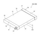
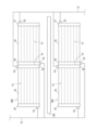
- FIG. 1 is a perspective view of an agricultural house to which a temperature adjustment system according to a first embodiment of the present invention is applied.
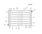
- FIG. 2 is a perspective view of a temperature adjustment panel according to the first embodiment.
- FIG. 2 is an exploded perspective view of the temperature adjustment panel according to the first embodiment.
- FIG. 2 is a cross-sectional view of a temperature adjustment panel and a cultivation bed according to the first embodiment.
- FIG. 2 is a vertical cross-sectional view of the temperature adjustment panel according to the first embodiment.
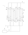
- FIG. 3 is a system diagram showing the flow of a heat medium in the temperature adjustment system according to the first embodiment.
- FIG. 3 is an exploded perspective view of a temperature adjustment panel according to a second embodiment of the present invention.
- FIG. 7 is a vertical cross-sectional view of a temperature adjustment panel according to a second embodiment.
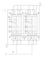
- FIG. 7 is a system diagram showing the flow of a heat medium in the temperature adjustment system according to the second embodiment.
- FIG. 7 is an exploded perspective view of a temperature adjustment panel according to a third embodiment.
- FIG. 7 is a vertical cross-sectional view of a temperature adjustment panel according to a third embodiment.
- FIG. 7 is a system diagram showing the flow of a heat medium in a temperature adjustment system according to a third embodiment.
- FIG. 7 is a system diagram showing the flow of a heat medium in the temperature adjustment system according to the fourth embodiment.
- FIG. 7 is a system diagram showing the flow of a heat medium in the temperature adjustment system according to the fifth embodiment.
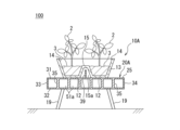
- FIG. 7 is a cross-sectional view of a temperature adjustment panel and a cultivation bed according to a sixth embodiment.
- FIG. 7 is a cross-sectional view of a temperature adjustment panel and a cultivation bed according to an eleventh embodiment.
- FIG. 7 is a cross-sectional view of a temperature adjustment panel and a cultivation bed according to a twelfth embodiment.
- FIG. 7 is a cross-sectional view of a temperature adjustment panel and a cultivation bed according to a thirteenth embodiment.
- FIG. 7 is a cross-sectional view of a temperature adjustment panel and a cultivation bed according to a fifteenth embodiment.
- FIG. 7 is a cross-sectional view of a temperature adjustment panel and a cultivation bed according to a sixteenth embodiment.
- FIG. 7 is a cross-sectional view of a temperature adjustment panel and a cultivation bed according to an eighteenth embodiment.
- FIG. 7 is a cross-sectional view of a temperature adjustment panel and a cultivation bed according to a nineteenth embodiment.
- FIG. 7 is a cross-sectional view of a temperature adjustment panel and a cultivation bed according to a twentieth embodiment.
- a temperature adjustment system 1 is used to assist the growth of a plant 2.
- the plants 2 are preferably crops (agricultural crops such as feed crops, horticultural crops, and craft crops).
- the temperature adjustment system 1 adjusts the ambient temperature of the plants 2 and the medium 3 in which they are planted. Temperature can be adjusted more effectively in a closed environment, and the temperature adjustment system 1 is suitably applied to a closed environment such as the agricultural house 100.
- the plant 2 is also suitable if it is suitable for greenhouse cultivation, and in this respect, general crops and horticultural crops are suitable examples among agricultural crops. Common crops include wheat, rice, tubers, and beans. Horticultural crops include vegetables, fruit trees and flowers.
- Medium 3 is a growth medium for plants 2.
- the medium 3 is appropriately selected from soil, rock wool, culture solution, etc., taking into consideration the compatibility with the plants 2 to be cultivated.
- the agricultural house 100 is constructed on a substantially horizontal rectangular site.
- the agricultural house 100 has a frame 101 made of steel or extruded aluminum.
- the entire frame 101 is covered with an outer skin (not shown) made of a light-transmitting material (for example, polyvinyl chloride). Thereby, the inside of the agricultural house 100 is protected from wind and rain.
- a light-transmitting material for example, polyvinyl chloride
- the frame 101 consists of pillars 102 erected at the four corners of the site and in the middle thereof, a pair of girders 103 that span the upper ends of the columns 102, a plurality of beams 104 that span between the girders 103, and the girders 103 and It includes a roof frame 105 provided on a beam 104.
- the shape of the roof is not particularly limited, and may be gable-shaped or arch-shaped, for example.
- the long sides of the site and the girders 103 are oriented north-south, and the short sides of the site and the beams 104 are oriented east-west.
- the direction in which the girders 103 extend will be referred to as the "girder direction" and the direction in which the beams 104 will extend will be referred to as the "beam direction.”
- the temperature adjustment system 1 includes multiple rows of cultivation beds 10A, 10B, 10C, and one or more temperature adjustment panels 20A, 20B.
- Cultivation beds 10A, 10B, 10C and temperature adjustment panels 20A, 20B are installed in agricultural house 100.
- the number of rows of cultivation beds 10A, 10B, and 10C is not limited to three, and may be one row or multiple rows other than three.
- Each cultivation bed 10A, 10B, 10C has an elongated rectangular shape in plan view.
- the longitudinal direction of the cultivation beds 10A, 10B, 10C will be referred to as the "bed longitudinal direction”
- the direction perpendicular to the bed longitudinal direction will be referred to as the "bed width direction”.
- Each cultivation bed 10A, 10B, 10C receives the medium 3.
- the medium 3 is soil.
- a plurality of plants 2 are planted in a medium 3 at intervals in the longitudinal direction of the bed.
- the cultivation bed 10A may have any structure as long as it can receive the required medium 3.
- the cultivation bed 10A includes a container body 11.
- the container body 11 has a bottom wall 12 and a peripheral wall 13 erected from the periphery of the bottom wall 12, and the bottom wall 12 and the peripheral wall 13 form a receiving portion 14 that receives the culture medium 3.
- the receiving portion 14 is open upward.
- the cultivation bed 10A is supported on the site of the agricultural house 100 via legs 19 extending downward from the bottom wall 12.
- the medium 3 is received into the receiving part 14 from above.
- the material of the cultivation bed 10A is not particularly limited. The same applies to the other cultivation beds 10B and 10C.
- Each of the cultivation beds 10A, 10B, and 10C is installed in the agricultural house 100 with the longitudinal direction of the bed facing toward the girder.
- the plurality of rows of cultivation beds 10A, 10B, and 10C extend parallel to each other and are arranged at intervals in the beam direction or bed width direction.
- temperature adjustment panels 20A and 20B are panel-shaped with a wall thickness t20 (see FIG. 4).
- the temperature adjustment panels 20A, 20B are flat rectangular panels and are independent from the cultivation beds 10A, 10B, 10C.
- the temperature adjustment panels 20A, 20B are arranged between two rows adjacent to each other in the bed width direction among the plurality of rows of cultivation beds 10A, 10B, 10C. Temperature adjustment panel 20A is arranged between cultivation beds 10A and 10B, and temperature adjustment panel 20B is arranged between cultivation beds 10B and 10C. In other words, the central cultivation bed 10B is arranged between the two temperature adjustment panels 20A, 20B in the bed width direction.
- the thickness direction of the temperature adjustment panels 20A and 20B is oriented in the bed width direction (beam direction).
- the panel longitudinal direction of the temperature adjustment panels 20A, 20B is oriented in the bed longitudinal direction (girder direction).
- the panel width direction of the temperature adjustment panels 20A and 20B is oriented in the vertical direction.
- the structure of the temperature adjustment panel 20A will be explained with reference to FIGS. 2 to 5. Since the temperature adjustment panels 20A and 20B have the same structure, a description of the temperature adjustment panel 20B will be omitted.
- the temperature adjustment panel 20A includes a main body 25 and a pair of headers 26 and 27 (a first header 26 and a second header 27).
- the main body portion 25 is an extruded metal material, and the longitudinal direction of the panel is the extrusion direction. Any metal material may be used as long as it can be used for extrusion molding, and examples thereof include aluminum, aluminum alloy, silver, and copper alloy. In this embodiment, the main body portion 25 is made of aluminum alloy.
- the main body portion 25 has a pair of main walls 31 and 32, a pair of end walls 33 and 34, and a plurality of partition walls 35.
- the main walls 31 and 32 are opposed to each other in the thickness direction of the temperature adjustment panels 20A and 20B.
- Each of the main walls 31 and 32 has a rectangular shape when viewed from the side, and extends in the panel longitudinal direction and the panel width direction perpendicular to the panel longitudinal direction and the thickness direction. Note that the wall thickness t20 is the distance between the outer surfaces of the pair of main walls 31 and 32.
- the end walls 33 and 34 extend in the longitudinal direction and thickness direction of the panel.
- the end wall 33 connects one end of the pair of main walls 31, 32 in the panel width direction, and the end wall 34 connects the other ends of the pair of main walls 31, 32.
- the main body portion 25 forms a hollow portion 36 surrounded by main walls 31, 32 and end walls 33, 34.
- the hollow portion 36 opens at both ends of the main body portion 25 in the longitudinal direction of the panel.
- the plurality of partition walls 35 are arranged in the hollow portion 36 at intervals in the panel width direction, and extend parallel to each other in the panel longitudinal direction.
- Each partition wall 35 is joined to the inner surface of the main wall 31 at one end in the thickness direction, and to the inner surface of the main wall 32 at the other end in the thickness direction.
- the plurality of partition walls 35 partition the hollow portion 36 into a plurality of long holes 36a to 36g arranged in the panel width direction. That is, the main body portion 25 is made of an extruded material having a multi-chamber structure.
- Each of the elongated holes 36a to 36g is defined by the inner surfaces of the pair of main walls 31 and 32, and the inner surfaces of two adjacent ones of the pair of end walls 33 and 34 and the plurality of partition walls 35.
- the number of long holes 36a to 36g is one more than the number of partition walls 35. In this example, the number of long holes 36a to 36g is seven, but it can be changed as appropriate.
- the main walls 31 and 32 form a contour that is longer than the wall thickness t20 in a cross section (a cross section perpendicular to the longitudinal direction of the panel).
- the main walls 31 and 32 have a flat plate shape, and the main body portion 25 has a flat rectangular panel shape.
- the outlines of the main walls 31, 32 are linear. If expressed more strictly two-dimensionally taking into account the thicknesses of the main walls 31 and 32, the outline is an elongated rectangle.
- the length of the profile to be compared with the wall thickness t20 may be defined as the total length of the profile, or may be defined as the distance from one end of the profile to the other end in the panel width direction. In this embodiment, since the contour is a straight line extending in a direction perpendicular to the thickness direction, both definitions are the same.
- the outlines of the main walls 31 and 32 are longer than the wall thickness t20. That is, the main walls 31, 32 and the temperature adjustment panel 20A are elongated in the panel width direction relative to the thickness direction, and the temperature adjustment panel 20A is wall-shaped or panel-shaped rather than circular or square tubular. be.
- the aspect ratio of the cross section of the main body portion 25 is a value significantly different from 1. Note that the length of the main walls 31, 32 in the longitudinal direction of the panel is longer than the length of the outline of the main walls 31, 32 in the cross section.
- the first header 26 is attached to one end of the main body portion 25 in the longitudinal direction of the panel, and closes the opening at one end of the hollow portion 36.
- the second header 27 is attached to the other end of the main body portion 25 in the panel longitudinal direction, and closes the opening on the other end side of the hollow portion 36 .
- the first header 26 has a lid plate 41 , a peripheral wall 42 that stands up from the peripheral edge of the lid plate 41 , and a recess 43 surrounded by the lid plate 41 and the peripheral wall 42 . It opens on the other side.
- the cross section of the recess 43 (the cross section of the inner circumferential surface of the peripheral wall 42) has the same shape as the cross section of the outer circumferential surface of the main body portion 25 (in this embodiment, a rectangular shape).
- the first header 26 is fitted onto one end of the main body 25 and is liquid-tightly joined to the main body 25. When attached to the main body 25 , the inner surface of the cover plate 41 is brought into surface contact with the rectangular window frame-shaped end surface of one end of the main body 25 .
- the second header 27 is also configured in the same manner as the first header 26, and is attached to the other end of the main body 25 in the panel longitudinal direction in the same manner as the first header 26.
- one end in the panel longitudinal direction is offset inward of the main body 25 with respect to the end surface of one end of the main body 25 that is in surface contact with the lid plate 41. . Therefore, all the elongated holes 36a to 36g open inside the main body portion 25 at one end side.
- the long holes 36a to 36g communicate with each other via a communication portion 37 extending in the panel width direction within the main body 25 between the opening of the main body 25 and the long holes 36a to 36g. This also applies to the other end of the panel in the longitudinal direction.
- the temperature adjustment panel 20A forms therein a heat medium flow path 51 through which a heat medium having a temperature higher or lower than the environmental temperature flows.
- the environmental temperature is the temperature of the environment where the plant 2 is placed.
- the environmental temperature is set at a predetermined distance away from the cultivation beds 10A, 10B, and 10C in the direction of the digits within the agricultural house 100, that is, an area where the temperature can be controlled by the temperature adjustment panels 20A and 20B. It is the temperature at a point far away.
- the heat medium may be of any kind as long as it enables heat exchange, such as water or antifreeze containing ethylene glycol as a main component.
- the temperature adjustment panel 20A has an inlet 52 for causing the heat medium to flow into the heat medium flow path 51, and an outlet 53 for causing the heat medium to flow out from the heat medium flow path.
- a single inlet 52 is provided on the cover plate 41 of the first header 26 and a single outlet 53 is provided on the cover plate 41 of the second header 27 .
- the inlet 52 and the outlet 53 are arranged at ends opposite to each other in the panel width direction.
- the panel width direction is oriented in the vertical direction within the agricultural house 100.
- the temperature adjustment panel 20A is installed in the agricultural house 100 with the inlet 52 facing downward and the outlet 53 facing upward. Nipples for connecting hoses (not shown) through which a heat medium flows are fixed to the inlet 52 and the outlet 53.
- the heat medium flows into the communication portion 37 on one end side through the inlet 52, and further flows from the communication portion 37 into the plurality of long holes 36a to 36g.
- the heat medium flows into the communication portion 37 on the other end side through the long holes 36a to 36g, and further flows out from the temperature adjustment panel 20A through the outlet 53.
- the heat medium flow path 51 is constituted by the communication section 37 on one end side, the plurality of elongated holes 36a to 36g, and the communication section 37 on the other end side.
- the plurality of long holes 36a to 36g constitute a plurality of individual heat medium flow paths 51a extending in the longitudinal direction of the panel within the temperature adjustment panel 20A.
- the communication portion 37 at one end functions as a distribution channel 51b that distributes the heat medium to each of the plurality of individual heat medium channels 51a.
- the communication portion 37 on the other end side functions as a recovery channel 51c that recovers the heat medium from each of the plurality of individual heat medium channels 51a.
- all the elongated holes 36a to 36g constitute an individual heat medium flow path 51a. Further, in all the elongated holes 36a to 36g, the heat medium flows in the same direction from one side to the other side in the longitudinal direction of the panel.
- the temperature adjustment system 1 includes a heat medium temperature management section 60.
- the heat medium temperature management section 60 includes a tank 61, a pump 62, a heater 63, a cooler 64, and a controller 80.
- Tank 61 stores a heat medium.
- the outlet of the tank 61 is connected to the suction port of the pump 62.
- the pump 62 pumps the heat medium in the tank 61 through its discharge port.
- the tank 61 and the pump 62 may be placed inside the agricultural house 100 or outside the agricultural house 100.
- the discharge port of the pump 62 is connected to the inlet of the tank 61 via a heating line 71.
- the heater 63 is provided on the heating line 71.
- the heater 63 is, for example, a solar panel attached to the beam 104 of the agricultural house 100, and the heating medium flowing through the heating line 71 is heated by solar heat.
- the discharge port of the pump 62 is connected in parallel to the inlet ports 52 of the temperature adjustment panels 20A and 20B via a supply line 72.
- the outlet ports 53 of the temperature adjustment panels 20A and 20B are connected in parallel to the inlet of the tank 61 via a return line 73.
- a cooling line 74 is provided in the return line 73 as a detour. Cooler 64 is provided on cooling line 74 .
- the cooler 64 is, for example, a heat exchanger buried underground (for example, at a depth of 20 m) on the site of the agricultural house 100 or adjacent land.
- the discharge port of the pump 62 is connected to the inlet of the first three-way valve 65a, and the line from the pump 62 to the first three-way valve 65a serves as a heating line 71 and a supply line 72.
- the heating line 71 separates from the supply line 72 from the first three-way valve 65a and extends to the heater 63
- the supply line 72 separates from the supply line 72 from the first three-way valve 65a and extends to the temperature adjustment panels 20A, 20B.
- the first three-way valve 65a is switched between a heating state in which the discharge port is communicated with the heating line 71 and a supply state in which the discharge port is communicated with the supply line 72.
- the return line 73 is provided with a second three-way valve 65b.
- the cooling line 74 extends from the second three-way valve 65b and terminates at a portion of the return line 73 downstream of the second three-way valve 65b.
- the second three-way valve 65b has a direct connection state where the outlet ports 53 of the temperature adjustment panels 20A and 20B are connected to the inlet of the tank 61 without going through the cooler 64, and a direct connection state where the outlet ports 53 are connected to the inlet of the tank 61 via the cooler 64. It can be switched between the cooling state and connecting to the cooling state.
- the cooling line 74 and the return line 73 are each provided with check valves 66a and 66b before the confluence point, so that the heat medium from the cooling line 74 flows backward through the return line 73, and the heat medium from the return line 73 There is no possibility of reverse flow through the cooling line 74.
- the downstream end of the heating line 71 and the downstream end of the return line 73 are joined together to form one common line 75 connected to the inlet of the tank 61.
- the heating line 71 and the return line 73 are each provided with check valves 66c and 66d before the confluence point, so that the heating medium does not flow from the heating line 71 to the return line 73 or in the opposite direction. .
- the first three-way valve 65a and the second three-way valve 65b are electromagnetic valves.
- the controller 80 switches the states of the first three-way valve 65a and the second three-way valve 65b based on information necessary for control such as environmental temperature and time. This automates the management of heat medium flow and temperature.
- the controller 80 is provided on an operation panel (not shown) installed in the agricultural house 100.
- the controller 80 switches the first three-way valve 65a to the heating state.
- the state of the second three-way valve 65b is not particularly limited.
- the heat medium in the tank 61 flows through the heating line 71 and returns to the tank 61 .
- the heating medium is heated by solar heat in the heater 63.
- the heat medium heated during the day is stored in the tank 61.
- the controller 80 switches the first three-way valve 65a to the supply state and switches the second three-way valve 65b to the direct connection state.
- the heat medium in the tank 61 is supplied to the temperature adjustment panels 20A, 20B via the supply line 72, flows through the heat medium flow path 51 in the temperature control panels 20A, 20B, and is connected to the cooler 64 via the return line 73. It returns to tank 61 without passing through.
- the controller 80 switches the first three-way valve 65a to the supply state and switches the second three-way valve 65b to the cooling state, regardless of day or night.
- the heat medium in the tank 61 is supplied to the temperature adjustment panels 20A, 20B via the supply line 72, flows through the heat medium flow path 51 in the temperature adjustment panels 20A, 20B, and flows through the return line 73.
- the heat medium flows through the cooling line 74 and is cooled by the cooler 64, and the cooled heat medium is returned to the tank 61.
- the heat medium flows through the heat medium flow path 51 along the longitudinal direction of the panel, that is, the longitudinal direction of the bed.
- the outer surfaces of the pair of main walls 31, 32 of the temperature adjustment panels 20A, 20B are closely opposed to the cultivation bed 10 and the plants 2 extending upward therefrom in the panel width direction or the bed width direction.
- the pair of main walls 31 and 32 are heated by heat conduction from the heating medium, thereby warming the peripheral area of the outer surface.
- the culture medium 3 and the plants 2 exist in the surrounding area, that is, within a range whose temperature can be controlled by the temperature control panels 20A and 20B. In the cross section shown in FIG.
- the outline of the outer surface of the pair of main walls 31, 32 is longer than the wall thickness t20, and this outline extends in the vertical direction when the temperature adjustment panels 20A, 20B are installed. ing.
- the range in which the temperature can be controlled is expanded in the vertical direction compared to the water pipe, and the surroundings of the plants 2 and the culture medium 3 are kept at an appropriate temperature over a wider range. The same applies when suppressing an excessive temperature rise around the plants 2 and the medium 3 in summer. Thereby, it is possible to assist in promoting the growth of a wider variety of plants 2.
- the outer surfaces of the temperature adjustment panels 20A and 20B have light diffusing or reflecting properties.
- the outer surface may be painted white or left unpainted to obtain light diffusive or reflective properties.
- the outer surface diffuses or reflects sunlight that has passed through the outer skin of the agricultural house 100, and the plants 2 or the culture medium 3 are irradiated with the diffused light or reflected light. Thereby, light-repellent pests can be kept away from the plants 2 and the medium 3, and the growth of the plants 2 is promoted. Further, by directing the light toward the plants 2, photosynthesis of the plants 2 is promoted.
- One long hole 36d among the seven long holes 36a to 36g constitutes a gas flow path 56 through which gas containing carbon dioxide flows.
- the remaining long holes 36a to 36c and 36e to 36g constitute individual heat medium flow paths 51a.
- the long hole 36d is located at the center of the seven long holes 36a to 36g.
- one end in the panel longitudinal direction is flush with the end surface of one end of the main body 25 that is in surface contact with the cover plate 41.
- the other partition walls 35 are the same as those in the first embodiment.
- the long holes 36a to 36c communicate with each other via a one-side communication portion 37a extending in the panel width direction within the main body 25 between the opening of the main body 25 and the long holes 36a to 36c.
- the long holes 36e to 36g communicate with each other via the other side communication portion 37b that extends in the panel width direction within the main body 25 between the opening of the main body 25 and the long holes 36e to 36g. This also applies to the other end of the panel in the longitudinal direction.
- the pair of main walls 31 and 32 are provided with a plurality of elongated holes 36d, that is, a plurality of ejection ports 38 that communicate the gas flow path 56 with the outside. 32 spouts 38 (see FIG. 7B).
- the plurality of jet ports 38 are arranged at intervals in the extending direction of the gas flow path 56, that is, in the longitudinal direction of the panel.
- the first header 26 is provided with two inlets 52a and 52b and one gas inlet 57.
- the second header 27 is provided with two outlet ports 53a and 53b.
- the first inlet 52a communicates with the first outlet 53a via the one-side communication portion 37a of the first header 26, the three elongated holes 36a to 36c, and the one-side communication portion 37a of the second header 27.
- the second inlet 52b communicates with the second outlet 53b via the one-side communication portion 37a of the first header 26, the three elongated holes 36e to 36g, and the one-side communication portion 37a of the second header 27.
- the communication portions 37a, 37b of the first header 26 constitute a distribution flow path 51b
- the elongated holes 36a to 36c, 36d to 36e constitute an individual heat medium flow path 51a
- the communication portions 37a, 37b of the second header 27 constitute a distribution flow path 51b.
- a recovery channel 51c is configured.
- the first inlet 52a is arranged below the first outlet 53a, and the second inlet 52b is arranged below the second outlet 53b.
- the heat medium flows in the same direction.
- the gas inlet 57 is connected to a gas supply source 81 via a gas supply line 82.
- the gas supply source 81 may be a tank that stores high-pressure gas containing carbon dioxide, or may be a pump or a compressor that pumps air.
- Gas containing carbon dioxide is introduced into the gas passages 56 of the temperature adjustment panels 20A, 20B via the gas supply line 82 and the gas inlet 57.
- the introduced gas is ejected toward the plants 2 from the plurality of ejection ports 38. Thereby, the photosynthesis of the plant 2 is promoted.
- the main body part 25 includes the communication part 37 in the first embodiment (see FIGS. 3 and 5), and the one-side communication part 37a and the other-side communication part 37b in the second embodiment (see FIGS. 7A and 7B). (see) does not exist. This also applies to the other end of the panel in the longitudinal direction.
- the first header 26 is provided with three inlets 52a, 52c, and 52f, three outlets 53b, 53e, and 53g, and one gas inlet 57.
- the second header 27 is provided with three inlets 52b, 52e, and 52g, and three outlets 53a, 53c, and 53f.
- the gas inlet 57 communicates with the elongated hole 36d, and the elongated hole 36d constitutes the gas flow path 56, as in the second embodiment.
- the long hole 36a communicates with the inlet 52a and the outlet 52b.
- the elongated hole 36a constitutes a first individual heat medium flow path 51a1 through which the heat medium flows from one side to the other side in the longitudinal direction of the panel.
- the long hole 36b communicates with the inlet 52b and the outlet 53b.
- the elongated hole 36b constitutes a second individual heat medium flow path 51a2 through which the heat medium flows from the other side to the one side in the longitudinal direction of the panel.
- the long holes 36c and 36f constitute a first individual heat medium flow path 51a1.
- the long holes 36d and 36g constitute a second individual heat medium flow path 51a2.
- the first individual heat medium flow paths 51a1 and the second individual heat medium flow paths 51a2 are arranged alternately in the panel width direction.
- the temperature of the heat medium may change due to heat exchange with the internal air of the agricultural house 100.
- the first individual heat medium flow path 51a1 through which the heat medium flows from one side to the other side, and the second individual heat medium flow path 51a2 through which the heat medium flows from the other side to one side are connected to the temperature adjustment panel 20A. , 20B, the ambient temperature on one side of the temperature adjustment panel 20A and the ambient temperature on the other side can be made homogeneous. Since the first individual heat medium flow paths 51a1 and the second individual heat medium flow paths 51a2 are arranged alternately, the temperature can be made uniform also in the vertical direction.
- the temperature adjustment panel 20A may include a plurality of main body parts 25 arranged in the longitudinal direction of the panel.
- the temperature adjustment panel 20A includes one or more intermediate headers 28 that connect the main body parts 25 to each other.
- the intermediate header 28 has a shape in which the cover plate 41 of the second header 27 and the cover plate 41 of the first header 26 are bonded back to back.
- One side in the longitudinal direction of the panel has the same structure as the second header 27, and the other side in the longitudinal direction of the panel has the same structure as the first header 26.
- the inlet 52 and the outlet 53 are provided in the peripheral wall 42 instead of the cover plate 41.
- the gas flow path 56 according to the second and third embodiments (see FIGS. 7A and 8A) is not provided in the illustrated example, the gas flow path 56 is also applicable to this embodiment.
- the individual heat medium flow paths 51a all allow the heat medium to flow from one side to the other side, but also in this embodiment, the first individual heat medium flow path 51a1 and the second individual heat medium flow path 51a2 (see FIG. 8B) may be set.
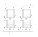
- one row of temperature adjustment panels 20A adjacent to the cultivation bed 10A is configured by arranging a plurality of temperature adjustment panels 20A1 and 20A2 in the longitudinal direction of the bed.
- a long temperature adjustment panel 20A can be provided according to the long cultivation beds 10A, 10B, 10C.
- the individual heat medium flow paths 51a in each temperature adjustment panel 20A1, 20A2 are oriented in the vertical direction. Thereby, the temperature around one side of the temperature adjustment panel 20A and the temperature around the other side can be made uniform. All the individual heat medium channels 51a allow the heat medium to flow from the bottom to the top. Thereby, it is possible to suppress air from accumulating in the heat medium flow path 51.
- the individual heat medium flow paths 51a are oriented in the vertical direction, but the individual heat medium flow paths 51a are As in the first to fourth embodiments, it may be oriented in the longitudinal direction of the bed.
- the individual heat medium flow paths 51a are oriented in the vertical direction, but the individual heat medium flow paths 51a are Similarly to the fourth embodiment, it may be oriented in the longitudinal direction of the bed. Also in this embodiment, the gas flow path 56 (see FIGS. 7A and 8A) can be applied, and the first individual heat medium flow path 51a1 and the second individual heat medium flow path 51a2 (see FIG. 8B) can be applied. Configurable.
- the temperature adjustment panel 20A was installed adjacent to the cultivation bed 10A, but in the present embodiment to the 20th embodiment, the temperature adjustment panel 120A partially controls the cultivation bed 10A. Configure.
- the temperature adjustment panel 20A constitutes the bottom of the cultivation bed 10A.
- the temperature adjustment panel 20A is supported on the site of the agricultural house 100 via the legs 19 with the pair of main walls 31 and 32 facing upward or downward.
- the container body 11 of the cultivation bed 10A is placed on the upper surface of the main wall 31. In this way, the temperature adjustment panel 20A functions as a pedestal on which the container body 11 is placed.
- the temperature of the bottom wall 12 of the container body 11 is adjusted by solid heat transfer. Further, the temperature of the peripheral wall 13 of the container body 11 is also adjusted by the temperature adjustment panel 20A. Thereby, the temperature of the culture medium 3 received in the container body 11 can be adjusted over a wide range.
- the container body 11 has a W-shaped cross section as a whole, and has an inverted V-shaped partition portion 15 at the center in the width direction.
- the two receiving parts 14 are arranged in the width direction with the partition part 15 interposed therebetween.
- the medium 3 is received in each of the two receiving parts 14.
- the temperature adjustment panel 20A functions as a pedestal on which the container body 11 is placed, similarly to the sixth embodiment.
- the partition wall portion 15 has a recess 15a facing upward from the lower surface.
- the temperature adjustment panel 20A has fins 39 protruding from the main wall 31, and the fins 39 are inserted into the recesses 15a. Thereby, even if the container body 11 has the partition wall part 15, the temperature of the partition wall part 15 can be adjusted by the fins 39.
- the long holes 36a to 36g are arranged linearly in the panel width direction, but in this embodiment, the central long hole 36d is connected to the other long holes 36a to 36c, 36e to 36g. It is offset in the thickness direction. Therefore, the main walls 31 and 32 are not flat, but have steps in the thickness direction at the portions that define the long holes 36d. Thereby, the stepped portion can be inserted into the recess 15a. Therefore, the temperature of the partition wall portion 15 can be adjusted in the same way as in the sixth embodiment.
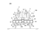
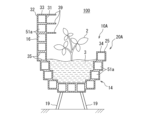
- the temperature adjustment panel 20A has a U-shaped cross section and is supported on the site of the agricultural house 100 via the legs 19.
- the contours of the outer surfaces of the pair of main walls 31, 32 are not linear or elongated rectangular as in the first to seventh embodiments.
- the contour may be convex downward, may be curved, or may be formed by a plurality of steps as shown in the illustrated example. In this embodiment as well, the contour is long with respect to the wall thickness t20.
- Cultivation bed 10A is received within temperature control panel 20A. Thereby, not only the bottom wall 12 but also the peripheral wall 13 of the container body 11 are opposed to the outer surface of the main wall 31 in the bed width direction. Therefore, compared to the sixth embodiment, it becomes easier to adjust the temperature of the culture medium 3.
- the temperature adjustment panel 20A has a U-shaped cross section, and has a bottom wall 20a and a pair of side walls 20b that protrude upward from both ends of the bottom wall 20a.
- the temperature adjustment panel 20A has a plurality of fins 39 protruding from the inner peripheral surfaces of the bottom wall portion 20a and the side wall portions 20b.
- the medium 3 is rock wool, for example. Unlike soil or culture solution, rock wool has a high ability to maintain its own shape without losing its shape, and the cultivation bed 10A does not necessarily have to include the container body 11 as in the above embodiment.
- the fins 39 contribute to stabilizing the position of such exposed rock wool with respect to the temperature adjustment panel 20A. That is, the fins 39 protruding from the inner surface of the side wall portion 20b stabilize the position of the rock wool in the panel width direction, and a portion of the fins 39 protruding from the inner surface of the bottom wall portion 20a also stabilizes the position of the rock wool in the panel width direction.
- the culture medium 3 Since the culture medium 3 is surrounded by the side wall, it is easy to adjust the temperature of the culture medium 3. Further, since the fins 39 are close to, in contact with, or immersed in the rock wool, the temperature of the culture medium 3 can be adjusted more easily.
- the cross-sectional structure of the temperature adjustment panel 20A is the same as in the ninth embodiment (see FIG. 12A).
- a culture solution is used as the culture medium 3
- the temperature adjustment panel 20A functions not as a pedestal that supports the container body 11, but rather as a receiving portion 14 that receives the liquid culture medium 3.
- the headers 26 and 27 of the temperature adjustment panel 20A also have a closing plate that closes the longitudinal end of the receiving portion 14 in order to prevent the culture solution from leaking out. Further, in order to manage the water quality and temperature of the culture solution, the temperature adjustment system 1 is added with a system for circulating the culture solution.
- the temperature of the culture medium 3 can be adjusted.
- the outer surface of the main wall 31 facing the culture medium 3 may be subjected to a surface treatment to prevent corrosion.
- the temperature adjustment panel 20A can be prevented from being corroded by the culture medium 3, and the material of the temperature adjustment panel 20A can be prevented from being eluted into the culture medium 3.
- the main body portion 25 of the temperature adjustment panel 20A is made of an extruded material having a large number of long holes.
- the liquid level of the medium 3 is approximately at the same height as the partition wall that partitions a pair of elongated holes arranged at the upper end of the medium. Therefore, the long holes at the upper end constitute the gas flow path 56, and the remaining long holes arranged below it constitute the individual heat medium flow path 51a. Thereby, it is possible to simultaneously promote photosynthesis with the gas ejected to the plants 2 and to adjust the temperature of the liquid medium 3.
- the cross-sectional structure of the temperature adjustment panel 20A is the same as in the tenth embodiment (see FIG. 12B).
- a culture solution is employed as in the eleventh embodiment.
- the bottom wall portion 20a and the pair of side wall portions 20b function as the receiving portion 14 that receives the culture medium 3.
- the temperature of the liquid culture medium 3 can be adjusted in the same manner as in the tenth embodiment and the eleventh embodiment.
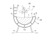
- the culture medium 3 as a culture solution is received in the temperature adjustment panel 20A in the same manner as in the tenth embodiment.
- the temperature adjustment panel 20A has a receiving section 14 having a U-shaped cross section for receiving the culture medium 3, and a vertical wall section 16 extending upward from one upper end of the receiving section 14, and has a J-shaped cross section as a whole. It is formed in the shape of The vertical wall portion 16 closely faces the plant 2 extending upward from the culture medium 3. Thereby, the temperature of the liquid medium 3 can be adjusted by the receiving part 14, and the temperature around the plant 2 extending upward from the medium 3 can be adjusted by the vertical wall part 16. The growth of the plants 2 cultivated in the culture solution can be further promoted.
- the temperature adjustment panel 20A similarly to the thirteenth embodiment, has a receiving portion 14 and a vertical wall portion 16.
- the temperature adjustment panel 20A has fins 39 protruding from the inner surface of the vertical wall portion 16 (the surface facing the plants 2). This makes it easier to adjust the temperature around the plant 2.
- the temperature adjustment panel 20A includes a receiving portion 14, a vertical wall portion 16, and fins 39. While the receiving portion 14 forms an individual heat medium flow path 51a, the vertical wall portion 16 does not have a hollow structure and is plate-shaped. The fins 39 protrude from such a vertical wall portion 16. Also in this embodiment, the temperature around the culture medium 3 and the plants 2 can be easily adjusted. Note that the medium 3 may be soil or a culture solution.
- the temperature adjustment panel 20A includes a receiving portion 14, a vertical wall portion 16, and fins 39, as in the fifteenth embodiment.
- the receiving portion 14 forms an individual heat medium flow path 51a at its center, and is plate-shaped at both ends in the width direction. Also in this embodiment, the temperature around the culture medium 3 and the plants 2 can be easily adjusted. Note that the medium 3 may be soil or a culture solution.
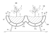
- the temperature adjustment panel 20A has a receiving portion 14 that receives the culture medium 3, similar to the eleventh embodiment or the twelfth embodiment.
- the receiving parts 14 form a pair in the width direction.
- a pair of receiving parts 14 are connected in the width direction and are integrated. This makes it easier to increase the cultivated area in the agricultural greenhouse 100 while adopting a configuration in which the temperature of the culture medium 3 can be adjusted.
- the temperature adjustment panel 20A has a pair of receiving portions 14 similarly to the seventeenth embodiment. Both ends of the receiving portion 14 in the width direction are plate-shaped as in the sixteenth embodiment. In this embodiment, a connection wall 17 is provided that connects the center portions of the receiving portions 14 in the vertical direction. This increases the section modulus in the region between the pair of receiving portions 14 and ensures strength.
- the temperature adjustment panel 20A has a pair of receiving portions 14 similarly to the seventeenth embodiment.
- the temperature adjustment panel 20A further includes a vertical wall portion 16 that projects upward from the connecting portion of the pair of receiving portions 14. Thereby, the temperature around the plants 2 planted in the culture medium 3 in the pair of receiving parts 14 can be adjusted.
- the temperature adjustment panel 20A has a pair of receiving portions 14 as in the eighteenth embodiment, and also has a vertical wall portion 16 as in the nineteenth embodiment. Also in this embodiment, the temperature around the plant 2 can be adjusted in the same manner as in the nineteenth embodiment.
- the method of molding the main body portion 25 is not particularly limited.
- the main body portion 25 is made of an extruded material, for example, but may be made of a single plate by roll forming. If extrusion molding is used, the main body portion 25 having the above structure can be easily manufactured.
- the tank may be separated into a heated high-temperature heat medium and a cooled low-temperature heat medium. Pumps can be added as appropriate to ensure the required pressure. Cooling only needs to be done underground, and groundwater (well water) may be used as a heat medium. In the case where the heat medium flow path is formed inside the pillars of the agricultural house 100, a portion of the pillar buried underground may constitute a cooling line.
- a temperature adjustment panel formed in a panel shape having a wall thickness and forming a heat medium flow path therein through which a heat medium having a temperature higher or lower than the environmental temperature flows,
- the temperature adjustment panel has a pair of main walls facing each other in the thickness direction of the temperature adjustment panel, and the pair of main walls form a longer profile than the wall thickness in a cross section.
- the heat medium flow path is defined by the pair of main walls
- the temperature adjustment panel extends along the longitudinal direction of the cultivation bed, and the outer surface of at least one of the pair of main walls is arranged close to the medium or the plant.
- the one or more rows of cultivation beds include multiple rows of the cultivation beds, The temperature adjustment panel is arranged between two rows of the cultivation beds that are adjacent to each other in the bed width direction, or one row of the cultivation bed is arranged between two of the temperature adjustment panels in the bed width direction. placed between The thickness direction of the temperature adjustment panel is oriented in the width direction of the bed, and the pair of main walls extend in the longitudinal direction and the vertical direction of the bed.
- the temperature adjustment system for plant growth according to aspect 1. (Aspect 3) The outer surface of at least one of the pair of main walls has light diffusivity or light reflectivity.
- the temperature adjustment system for plant growth according to aspect 2. The temperature adjustment panel constitutes the bottom of the cultivation bed.
- the temperature adjustment system for plant growth according to any one of aspects 1 to 3.
- the temperature adjustment panel has a receiving part that receives the medium in liquid form.
- the temperature adjustment panel has a vertical wall portion extending upward from one end of the receiving portion to be close to the plant.
- the temperature adjustment panel has a gas flow path that is provided independently of the heat medium flow path and allows gas containing carbon dioxide to flow therethrough, A spout is provided on the outer surface of at least one of the pair of main walls for spouting the gas in the gas flow path toward the plant.
- the temperature adjustment system for plant growth according to any one of aspects 1 to 6.
- the temperature adjustment panel forms a plurality of the heat medium flow paths extending parallel to each other.
- the temperature adjustment system for plant growth according to any one of aspects 1 to 7.
- the plurality of heat medium flow paths are arranged between the pair of main walls along the contour of the cross section of the main wall.
- the temperature adjustment system for plant growth according to aspect 8. (Aspect 10) the plurality of heat medium flow paths extend in the longitudinal direction of the bed;
- the plurality of heat medium flow paths include one or more first heat medium flow paths that allow the heat medium to flow in one direction, and one or more second heat medium flow paths that allow the heat medium to flow in a direction opposite to the one direction.
- the temperature adjustment system for plant growth according to aspect 10 The temperature adjustment system for plant growth according to aspect 10.
- the first heat medium flow path and the second heat medium flow path are alternately arranged along the cross section of the pair of main walls.
- the plurality of heat medium flow paths extend in a direction intersecting the longitudinal direction of the bed;
- the temperature adjustment panel has a hollow part that constitutes the heat medium flow path, and includes a main body part molded from an extruded material.
- the temperature adjustment panel further includes a pair of headers that close the opening of the hollow portion at each end of the extruded material, The pair of headers are provided with an inlet for causing the heat medium to flow into the heat medium flow path, and an outlet for causing the heat medium to flow out from the heat medium flow path.
- a temperature adjustment panel for assisting the growth of plants planted in a medium received in one or more rows of cultivation beds extending in the longitudinal direction of the bed comprising: A main body formed in a panel shape having a wall thickness and forming a heat medium flow path therein through which a heat medium having a temperature higher or lower than the environmental temperature flows, The main body portion constitutes a bottom portion of the cultivation bed, and the outer surface of one of the pair of main walls constitutes an inner bottom surface of the cultivation bed.
- Temperature control panel for plant growth for plant growth.
Landscapes
- Life Sciences & Earth Sciences (AREA)
- Environmental Sciences (AREA)
- Chemical & Material Sciences (AREA)
- Chemical Kinetics & Catalysis (AREA)
- Soil Sciences (AREA)
- Cultivation Of Plants (AREA)
- Hydroponics (AREA)
- Cultivation Receptacles Or Flower-Pots, Or Pots For Seedlings (AREA)
Abstract
Description
図1を参照して、第1実施形態に係る温度調整システム1は、植物2の生育を補助するために利用される。植物2は、好ましくは、作物(飼料作物、園芸作物、および工芸作物等の農作物)である。温度調整システム1は、植物2およびこれが植栽された培地3の周辺温度を調整する。温度は、閉鎖環境においてより効果的に調整可能であり、温度調整システム1は、農業ハウス100のような閉鎖環境に好適に適用される。植物2も、ハウス栽培に適していれば好適であり、この点で、一般作物および園芸作物は、農作物のなかでも好適例である。一般作物は、麦類、稲類、イモ類、および豆類を含む。園芸作物は、野菜、果樹および花卉を含む。培地3は、植物2の生育媒体である。培地3は、栽培される植物2との相性を考慮して、土壌、ロックウール、および培養液などから適宜選択される。
次に、図7A~Cを参照して、上記実施形態との相違を中心に、本発明の第2実施形態について説明する。本実施形態においても、温度調整パネル20A,20Bは互いに同一の構造を有するため、温度調整パネル20Bの説明は省略する。
次に、図8A~Cを参照して、上記実施形態との相違を中心に、本発明の第3実施形態について説明する。本実施形態においても、温度調整パネル20A,20Bは互いに同一の構造を有するため、温度調整パネル20Bの説明は省略する。
次に、図9を参照して、上記実施形態との相違を中心に、本発明の第4実施形態について説明する。本実施形態においても、温度調整パネル20A,20Bは互いに同一の構造を有するため、温度調整パネル20Bの説明は省略する。
次に、図10を参照して、上記実施形態との相違を中心に、本発明の第5実施形態について説明する。本実施形態においても、温度調整パネル20A,20Bは互いに同一の構造を有するため、温度調整パネル20Bの説明は省略する。
次に、図11Aを参照して、上記実施形態との相違を中心に、本発明の第6実施形態について説明する。
次に、図11Bを参照して、上記実施形態との相違を中心に、本発明の第7実施形態について説明する。
次に、図11Cを参照して、上記実施形態との相違を中心に、本発明の第8実施形態について説明する。
次に、図12Aを参照して、上記実施形態との相違を中心に、本発明の第9実施形態について説明する。
次に、図12Bを参照して、上記実施形態との相違を中心に、本発明の第10実施形態について説明する。
次に、図13Aを参照して、上記実施形態との相違を中心に、本発明の第11実施形態について説明する。
次に、図13Bを参照して、上記実施形態との相違を中心に、本発明の第12実施形態について説明する。
次に、図14Aを参照して、上記実施形態との相違を中心に、本発明の第13実施形態について説明する。
次に、図14Bを参照して、上記実施形態との相違を中心に、本発明の第14実施形態について説明する。
次に、図15Aを参照して、上記実施形態との相違を中心に、本発明の第15実施形態について説明する。
次に、図15Bを参照して、上記実施形態との相違を中心に、本発明の第16実施形態について説明する。
次に、図16Aを参照して、上記実施形態との相違を中心に、本発明の第17実施形態について説明する。
次に、図16Bを参照して、上記実施形態との相違を中心に、本発明の第18実施形態について説明する。
次に、図17Aを参照して、上記実施形態との相違を中心に、本発明の第19実施形態について説明する。
次に、図17Bを参照して、上記実施形態との相違を中心に、本発明の第20実施形態について説明する。
(態様1)
培地に植栽される植物の生育を補助するための温度調整システムであって、
前記培地を受容する1列以上の長尺の栽培ベッドと、
壁厚を有するパネル状に形成され、環境温度よりも高温または低温の熱媒が通流する熱媒流路をその内部に形成する温度調整パネルと、を備え、
前記温度調整パネルが、前記温度調整パネルの厚さ方向に互いに対向される一対の主壁を有し、前記一対の主壁は、横断面において、前記壁厚よりも長尺な輪郭を形成し、前記熱媒流路が、前記一対の主壁により画定され、
前記温度調整パネルが、前記栽培ベッドのベッド長手方向に沿って延び、前記一対の主壁の少なくとも一方の外表面が、前記培地または前記植物に近接して配置される、
植物生育用の温度調整システム。
(態様2)
前記1列以上の栽培ベッドが、複数列の前記栽培ベッドを含み、
前記温度調整パネルが、複数列の前記栽培ベッドのうちベッド幅方向において互いに隣接する2列の間に配置され、または、1列の前記栽培ベッドが、前記ベッド幅方向において2つの前記温度調整パネルの間に配置され、
前記温度調整パネルの前記厚さ方向が、前記ベッド幅方向に向けられ、前記一対の主壁が、前記ベッド長手方向および鉛直方向に延びる、
態様1に記載の植物生育用の温度調整システム。
(態様3)
前記一対の主壁の少なくとも一方の前記外表面が、光拡散性または光反射性を有する、
態様2に記載の植物生育用の温度調整システム。
(態様4)
前記温度調整パネルが、前記栽培ベッドの底部を構成する、
態様1から3のいずれかに記載の植物生育用の温度調整システム。
(態様5)
前記温度調整パネルが、液状の前記培地を受容する受容部を有する、
態様4に記載の植物生育用の温度調整システム。
(態様6)
前記温度調整パネルが、前記受容部の一端から上方に延長されて前記植物と近接する縦壁部を有する、
態様5に記載の植物生育用の温度調整システム。
(態様7)
前記温度調整パネルが、前記熱媒流路とは独立して設けられ、二酸化炭素を含むガスを通流させるガス流路を有し、
前記一対の主壁の前記少なくとも一方の前記外表面に、前記ガス流路内のガスを前記植物に向けて噴出する噴出口が設けられている、
態様1から6のいずれかに記載の植物生育用の温度調整システム。
(態様8)
前記温度調整パネルは、互いに平行に延びる複数の前記熱媒流路を形成する、
態様1から7のいずれかに記載の植物生育用の温度調整システム。
(態様9)
前記複数の熱媒流路が、前記一対の主壁の間で、前記主壁の前記横断面の前記輪郭に沿って並べられている、
態様8に記載の植物生育用の温度調整システム。
(態様10)
前記複数の前記熱媒流路が、前記ベッド長手方向に延びる、
態様8に記載の植物生育用の温度調整システム。
(態様11)
前記複数の前記熱媒流路が、前記熱媒を一方向に流通させる1以上の第1熱媒流路と、熱媒を前記一方向とは逆方向に流通させる1以上の第2熱媒流路とを含む、
態様10に記載の植物生育用の温度調整システム。
(態様12)
前記第1熱媒流路と前記第2熱媒流路とが、前記一対の主壁の前記横断面に沿って交互に並べられている、
態様11に記載の植物生育用の温度調整システム。
(態様13)
前記複数の前記熱媒流路が、前記ベッド長手方向と交差する方向に延びる、
態様8に記載の植物生育用の温度調整システム。
(態様14)
前記温度調整パネルが、前記熱媒流路を構成する中空部を有し、押出材で成形された本体部を含む、
態様1から13のいずれかに記載の植物生育用の温度調整システム。
(態様15)
前記温度調整パネルが、前記押出材の両端部それぞれにおいて前記中空部の開口を塞ぐ一対のヘッダを更に含み、
前記一対のヘッダに、前記熱媒を前記熱媒流路に流入させる流入口と、前記熱媒を前記熱媒流路から流出させる流出口とが設けられている、
態様14に記載の植物生育用の温度調整システム。
(態様16)
ベッド長手方向に延びる1列以上の栽培ベッドに受容された培地に植栽される植物の生育を補助するための温度調整パネルであって、
壁厚を有するパネル状に形成され、環境温度よりも高温または低温の熱媒が通流する熱媒流路をその内部に形成する本体部、を備え、
前記本体部が、前記栽培ベッドの底部を構成し、一対の主壁の一方の外表面が、前記栽培ベッドの内底面を成す、
植物生育用の温度調整パネル。
2 植物
3 培地
10A,10B,10C 栽培ベッド
20A,20B 温度調整パネル
14 受容部
16 縦壁部
21 熱媒流路
25 本体部
26,27 ヘッダ
31,32 主壁
33,34 端壁
35 隔壁
38 噴出口
51 熱媒流路
51a 個別熱媒流路
51a1 第1個別熱媒流路
51a2 第2個別熱媒流路
52 流入口
53 流出口
56 ガス流路
Claims (16)
- 培地に植栽される植物の生育を補助するための温度調整システムであって、
前記培地を受容する1列以上の長尺の栽培ベッドと、
壁厚を有するパネル状に形成され、環境温度よりも高温または低温の熱媒が通流する熱媒流路をその内部に形成する温度調整パネルと、を備え、
前記温度調整パネルが、前記温度調整パネルの厚さ方向に互いに対向される一対の主壁を有し、前記一対の主壁は、横断面において、前記壁厚よりも長尺な輪郭を形成し、前記熱媒流路が、前記一対の主壁により画定され、
前記温度調整パネルが、前記栽培ベッドのベッド長手方向に沿って延び、前記一対の主壁の少なくとも一方の外表面が、前記培地または前記植物に近接して配置される、
植物生育用の温度調整システム。 - 前記1列以上の栽培ベッドが、複数列の前記栽培ベッドを含み、
前記温度調整パネルが、複数列の前記栽培ベッドのうちベッド幅方向において互いに隣接する2列の間に配置され、または、1列の前記栽培ベッドが、前記ベッド幅方向において2つの前記温度調整パネルの間に配置され、
前記温度調整パネルの前記厚さ方向が、前記ベッド幅方向に向けられ、前記一対の主壁が、前記ベッド長手方向および鉛直方向に延びる、
請求項1に記載の植物生育用の温度調整システム。 - 前記一対の主壁の少なくとも一方の前記外表面が、光拡散性または光反射性を有する、
請求項2に記載の植物生育用の温度調整システム。 - 前記温度調整パネルが、前記栽培ベッドの底部を構成する、
請求項1に記載の植物生育用の温度調整システム。 - 前記温度調整パネルが、液状の前記培地を受容する受容部を有する、
請求項4に記載の植物生育用の温度調整システム。 - 前記温度調整パネルが、前記受容部の一端から上方に延長されて前記植物と近接する縦壁部を有する、
請求項5に記載の植物生育用の温度調整システム。 - 前記温度調整パネルが、前記熱媒流路とは独立して設けられ、二酸化炭素を含むガスを通流させるガス流路を有し、
前記一対の主壁の前記少なくとも一方の前記外表面に、前記ガス流路内のガスを前記植物に向けて噴出する噴出口が設けられている、
請求項1に記載の植物生育用の温度調整システム。 - 前記温度調整パネルは、互いに平行に延びる複数の前記熱媒流路を形成する、
請求項1から7のいずれか1項に記載の植物生育用の温度調整システム。 - 前記複数の熱媒流路が、前記一対の主壁の間で、前記主壁の前記横断面の前記輪郭に沿って並べられている、
請求項8に記載の植物生育用の温度調整システム。 - 前記複数の前記熱媒流路が、前記ベッド長手方向に延びる、
請求項8に記載の植物生育用の温度調整システム。 - 前記複数の前記熱媒流路が、前記熱媒を一方向に流通させる1以上の第1熱媒流路と、熱媒を前記一方向とは逆方向に流通させる1以上の第2熱媒流路とを含む、
請求項10に記載の植物生育用の温度調整システム。 - 前記第1熱媒流路と前記第2熱媒流路とが、前記一対の主壁の前記横断面に沿って交互に並べられている、
請求項11に記載の植物生育用の温度調整システム。 - 前記複数の前記熱媒流路が、前記ベッド長手方向と交差する方向に延びる、
請求項8に記載の植物生育用の温度調整システム。 - 前記温度調整パネルが、前記熱媒流路を構成する中空部を有し、押出材で成形された本体部を含む、
請求項1から7のいずれか1項に記載の植物生育用の温度調整システム。 - 前記温度調整パネルが、前記押出材の両端部それぞれにおいて前記中空部の開口を塞ぐ一対のヘッダを更に含み、
前記一対のヘッダに、前記熱媒を前記熱媒流路に流入させる流入口と、前記熱媒を前記熱媒流路から流出させる流出口とが設けられている、
請求項14に記載の植物生育用の温度調整システム。 - ベッド長手方向に延びる1列以上の栽培ベッドに受容された培地に植栽される植物の生育を補助するための温度調整パネルであって、
壁厚を有するパネル状に形成され、環境温度よりも高温または低温の熱媒が通流する熱媒流路をその内部に形成する本体部、を備え、
前記本体部が、前記栽培ベッドの底部を構成し、一対の主壁の一方の外表面が、前記栽培ベッドの内底面を成す、
植物生育用の温度調整パネル。
Priority Applications (2)
| Application Number | Priority Date | Filing Date | Title |
|---|---|---|---|
| CN202380065955.2A CN119894369A (zh) | 2022-09-15 | 2023-06-29 | 植物生长用的温度调整系统及温度调整面板 |
| EP23865029.5A EP4552481A4 (en) | 2022-09-15 | 2023-06-29 | TEMPERATURE CONTROL SYSTEM AND TEMPERATURE CONTROL PANEL FOR PLANT GROWING |
Applications Claiming Priority (2)
| Application Number | Priority Date | Filing Date | Title |
|---|---|---|---|
| JP2022-147042 | 2022-09-15 | ||
| JP2022147042A JP2024042370A (ja) | 2022-09-15 | 2022-09-15 | 植物生育用の温度調整システムおよび温度調整パネル |
Publications (1)
| Publication Number | Publication Date |
|---|---|
| WO2024057667A1 true WO2024057667A1 (ja) | 2024-03-21 |
Family
ID=90274536
Family Applications (1)
| Application Number | Title | Priority Date | Filing Date |
|---|---|---|---|
| PCT/JP2023/024152 Ceased WO2024057667A1 (ja) | 2022-09-15 | 2023-06-29 | 植物生育用の温度調整システムおよび温度調整パネル |
Country Status (4)
| Country | Link |
|---|---|
| EP (1) | EP4552481A4 (ja) |
| JP (1) | JP2024042370A (ja) |
| CN (1) | CN119894369A (ja) |
| WO (1) | WO2024057667A1 (ja) |
Citations (7)
| Publication number | Priority date | Publication date | Assignee | Title |
|---|---|---|---|---|
| JP2011244705A (ja) * | 2010-05-24 | 2011-12-08 | Idemitsu Kosan Co Ltd | 植物栽培方法 |
| JP2012170349A (ja) * | 2011-02-18 | 2012-09-10 | Idemitsu Kosan Co Ltd | 温度制御用シート、植物栽培用温度制御方法、植物栽培用温度制御装置、植物栽培用ユニット、及び、植物栽培用プラント |
| JP2012228241A (ja) * | 2011-04-15 | 2012-11-22 | Daikin Industries Ltd | 空調システム |
| JP2017139983A (ja) * | 2016-02-09 | 2017-08-17 | シーアイ化成株式会社 | 培地栽培用容器 |
| JP2017148020A (ja) | 2016-02-26 | 2017-08-31 | 未来工業株式会社 | 育成補助装置及び植物育成装置 |
| JP2017153471A (ja) | 2016-02-26 | 2017-09-07 | 未来工業株式会社 | 育成補助装置及び植物育成装置 |
| JP2022147042A (ja) | 2021-03-23 | 2022-10-06 | 株式会社エヌ・ティ・ティ・データ | マッチング装置、マッチング方法、及びプログラム |
Family Cites Families (6)
| Publication number | Priority date | Publication date | Assignee | Title |
|---|---|---|---|---|
| DK53906C (da) * | 1935-04-02 | 1937-11-22 | Stralingswarmte Fa Nv | Anlæg til Fremme af Væksten hos Planter, Blomster og Frugter paa Friland. |
| AU535900B2 (en) * | 1980-03-06 | 1984-04-12 | Hydrobotanicals Company Inc. | Farming marine + fresh water hydrophytes |
| JPS5725559U (ja) * | 1980-07-22 | 1982-02-09 | ||
| NL1011236C2 (nl) * | 1999-02-08 | 2000-08-10 | R & R Systems B V | Inrichting voor het op een gewenste temperatuur houden van een planten te ondersteunen bed. |
| WO2003085329A1 (en) * | 2002-04-10 | 2003-10-16 | Neil Christopher Hellmann | A solar panel structure |
| CN112930978A (zh) * | 2021-03-17 | 2021-06-11 | 塔里木大学 | 一种重力循环热水大棚环保供热系统 |
-
2022
- 2022-09-15 JP JP2022147042A patent/JP2024042370A/ja active Pending
-
2023
- 2023-06-29 WO PCT/JP2023/024152 patent/WO2024057667A1/ja not_active Ceased
- 2023-06-29 EP EP23865029.5A patent/EP4552481A4/en active Pending
- 2023-06-29 CN CN202380065955.2A patent/CN119894369A/zh active Pending
Patent Citations (7)
| Publication number | Priority date | Publication date | Assignee | Title |
|---|---|---|---|---|
| JP2011244705A (ja) * | 2010-05-24 | 2011-12-08 | Idemitsu Kosan Co Ltd | 植物栽培方法 |
| JP2012170349A (ja) * | 2011-02-18 | 2012-09-10 | Idemitsu Kosan Co Ltd | 温度制御用シート、植物栽培用温度制御方法、植物栽培用温度制御装置、植物栽培用ユニット、及び、植物栽培用プラント |
| JP2012228241A (ja) * | 2011-04-15 | 2012-11-22 | Daikin Industries Ltd | 空調システム |
| JP2017139983A (ja) * | 2016-02-09 | 2017-08-17 | シーアイ化成株式会社 | 培地栽培用容器 |
| JP2017148020A (ja) | 2016-02-26 | 2017-08-31 | 未来工業株式会社 | 育成補助装置及び植物育成装置 |
| JP2017153471A (ja) | 2016-02-26 | 2017-09-07 | 未来工業株式会社 | 育成補助装置及び植物育成装置 |
| JP2022147042A (ja) | 2021-03-23 | 2022-10-06 | 株式会社エヌ・ティ・ティ・データ | マッチング装置、マッチング方法、及びプログラム |
Non-Patent Citations (1)
| Title |
|---|
| See also references of EP4552481A4 |
Also Published As
| Publication number | Publication date |
|---|---|
| EP4552481A4 (en) | 2025-12-17 |
| CN119894369A (zh) | 2025-04-25 |
| JP2024042370A (ja) | 2024-03-28 |
| EP4552481A1 (en) | 2025-05-14 |
Similar Documents
| Publication | Publication Date | Title |
|---|---|---|
| US12096727B2 (en) | Hybrid aeroponic/hydroponic growing system | |
| ES2364891T3 (es) | Biorreactor. | |
| US20090134242A1 (en) | Hydro-thermo irrigation mat | |
| TW201633900A (zh) | 高密度無土植物生長系統及方法 | |
| ES2668792B2 (es) | Modulo de jardineria vertical y unidad y sistema de jardineria vertical que lo incorpora | |
| KR102092127B1 (ko) | 다층재배용 점적강우관수 벙커식 비닐하우스 장치 | |
| US20140325909A1 (en) | Permeable Three Dimensional Multi-Layer Farming | |
| JP2002330640A (ja) | 送風散水式冷暖房装置 | |
| KR102650374B1 (ko) | 에어돔 스마트팜 | |
| JP7572583B2 (ja) | 農業ハウス | |
| WO2024057667A1 (ja) | 植物生育用の温度調整システムおよび温度調整パネル | |
| KR101404306B1 (ko) | 플라베니아 패널을 이용한 냉온수 순환구조를 갖는 온실 | |
| JP2006197843A (ja) | 水耕栽培装置 | |
| JP2004097062A (ja) | 培地カバーフィルム | |
| CN117597557A (zh) | 集热构件以及农业大棚 | |
| JP2023140297A (ja) | 果実栽培システム、果実栽培キット、及び果実の生産方法 | |
| CN220554311U (zh) | 蔬菜种植架 | |
| JP3031461U (ja) | 雨樋を利用した、立体水耕栽培装置 | |
| JP2007195478A (ja) | 茸類栽培用施設 | |
| CN222928984U (zh) | 一种适用于无土栽培的恒温中空管道系统 | |
| KR102711485B1 (ko) | 재배용 연결포트와 이를 이용한 재배시설 | |
| JP2001016991A (ja) | 栽培容器及び栽培棚 | |
| CN115702624A (zh) | 一种窗体花园的灵活多变造型设计组件和组合方法及窗体花园 | |
| KR102911739B1 (ko) | 수위조절기구를 구비한 수경식물 재배기 | |
| CN219877112U (zh) | 一种基质可控温的栽培装置 |
Legal Events
| Date | Code | Title | Description |
|---|---|---|---|
| 121 | Ep: the epo has been informed by wipo that ep was designated in this application |
Ref document number: 23865029 Country of ref document: EP Kind code of ref document: A1 |
|
| WWE | Wipo information: entry into national phase |
Ref document number: 2023865029 Country of ref document: EP |
|
| ENP | Entry into the national phase |
Ref document number: 2023865029 Country of ref document: EP Effective date: 20250204 |
|
| WWE | Wipo information: entry into national phase |
Ref document number: 202380065955.2 Country of ref document: CN |
|
| NENP | Non-entry into the national phase |
Ref country code: DE |
|
| WWP | Wipo information: published in national office |
Ref document number: 202380065955.2 Country of ref document: CN |
|
| WWP | Wipo information: published in national office |
Ref document number: 2023865029 Country of ref document: EP |