WO2024057877A1 - 気液分離器 - Google Patents
気液分離器 Download PDFInfo
- Publication number
- WO2024057877A1 WO2024057877A1 PCT/JP2023/030675 JP2023030675W WO2024057877A1 WO 2024057877 A1 WO2024057877 A1 WO 2024057877A1 JP 2023030675 W JP2023030675 W JP 2023030675W WO 2024057877 A1 WO2024057877 A1 WO 2024057877A1
- Authority
- WO
- WIPO (PCT)
- Prior art keywords
- water
- gas
- water storage
- liquid separator
- discharge hole
- Prior art date
- Legal status (The legal status is an assumption and is not a legal conclusion. Google has not performed a legal analysis and makes no representation as to the accuracy of the status listed.)
- Ceased
Links
Images


Classifications
-
- H—ELECTRICITY
- H01—ELECTRIC ELEMENTS
- H01M—PROCESSES OR MEANS, e.g. BATTERIES, FOR THE DIRECT CONVERSION OF CHEMICAL ENERGY INTO ELECTRICAL ENERGY
- H01M8/00—Fuel cells; Manufacture thereof
- H01M8/04—Auxiliary arrangements, e.g. for control of pressure or for circulation of fluids
- H01M8/04082—Arrangements for control of reactant parameters, e.g. pressure or concentration
- H01M8/04089—Arrangements for control of reactant parameters, e.g. pressure or concentration of gaseous reactants
- H01M8/04119—Arrangements for control of reactant parameters, e.g. pressure or concentration of gaseous reactants with simultaneous supply or evacuation of electrolyte; Humidifying or dehumidifying
- H01M8/04156—Arrangements for control of reactant parameters, e.g. pressure or concentration of gaseous reactants with simultaneous supply or evacuation of electrolyte; Humidifying or dehumidifying with product water removal
- H01M8/04164—Arrangements for control of reactant parameters, e.g. pressure or concentration of gaseous reactants with simultaneous supply or evacuation of electrolyte; Humidifying or dehumidifying with product water removal by condensers, gas-liquid separators or filters
-
- B—PERFORMING OPERATIONS; TRANSPORTING
- B01—PHYSICAL OR CHEMICAL PROCESSES OR APPARATUS IN GENERAL
- B01D—SEPARATION
- B01D45/00—Separating dispersed particles from gases or vapours by gravity, inertia, or centrifugal forces
- B01D45/04—Separating dispersed particles from gases or vapours by gravity, inertia, or centrifugal forces by utilising inertia
- B01D45/08—Separating dispersed particles from gases or vapours by gravity, inertia, or centrifugal forces by utilising inertia by impingement against baffle separators
-
- Y—GENERAL TAGGING OF NEW TECHNOLOGICAL DEVELOPMENTS; GENERAL TAGGING OF CROSS-SECTIONAL TECHNOLOGIES SPANNING OVER SEVERAL SECTIONS OF THE IPC; TECHNICAL SUBJECTS COVERED BY FORMER USPC CROSS-REFERENCE ART COLLECTIONS [XRACs] AND DIGESTS
- Y02—TECHNOLOGIES OR APPLICATIONS FOR MITIGATION OR ADAPTATION AGAINST CLIMATE CHANGE
- Y02E—REDUCTION OF GREENHOUSE GAS [GHG] EMISSIONS, RELATED TO ENERGY GENERATION, TRANSMISSION OR DISTRIBUTION
- Y02E60/00—Enabling technologies; Technologies with a potential or indirect contribution to GHG emissions mitigation
- Y02E60/30—Hydrogen technology
- Y02E60/50—Fuel cells
Definitions
- the present disclosure relates to a gas-liquid separator.
- Patent Document 1 discloses a fuel cell system equipped with a freeze suppressant circulation unit for circulating a freeze suppressant in the exhaust gas passage in order to suppress freezing of water passing through the exhaust gas passage discharged from the fuel cell. Are listed.
- Patent Document 1 in order to suppress the freezing of produced water in the oxidation off-gas passage, a freezing inhibitor using ethylene glycol is injected into the oxidation off-gas passage, and the produced water is frozen by heating in the downstream part of the oxidation off-gas passage.
- a configuration is described in which the inhibitor is separated, recovered, and reused.
- Patent Document 2 discloses a configuration in which water separated from fuel off-gas discharged from a fuel cell stack by a gas-liquid separator is sent from a fluid introduction part to a valve device, and is drained under control of the valve device.
- a fuel cell system is described in which a heating device is arranged in the inner hole of the fuel cell system.
- Patent Document 2 a PTC heater that generates heat by power supply as a heating device is arranged at the end of a cylindrical cover main body, and when water inside the cover main body freezes, the heat generated by the PTC heater thaws the water. It describes what to do.
- Patent Document 3 discloses that fuel exhaust gas discharged from an anode electrode is separated into gas and liquid in a gas-liquid separator, compressed oxidizing gas is introduced into a discharge passageway for discharging the liquid, and the compressed oxidizing gas is heated by the heat of the compressed oxidizing gas. , a fuel cell system that heats the exhaust flow path and its vicinity is described.
- This Patent Document 3 also describes a heater unit that heats compressed oxidant gas guided to the discharge flow path.
- the fuel off-gas from which water has been removed by a gas-liquid separator is added to the fuel gas supply flow path. It is being brought back.
- a gas-liquid separator is used in a form that temporarily stores separated water at the bottom and discharges the stored water to the outside by opening a valve at a predetermined timing. has been done.
- Patent Document 1 In order to eliminate such inconveniences, it is conceivable to prevent freezing using a freezing inhibitor described in Patent Document 1.
- water is evaporated by heating with a heater.
- the electric current consumed by the heater increases and the mechanism for recovering the anti-freeze agent may become complicated.
- the valve device in a configuration using a PTC heater, can also be heated by the heat of the PTC heater due to energization.
- the PTC heater and the valve device are separated from each other, and it could be imagined that it would take time to defreeze the area near the valve device.
- the PCT heater may impede the flow of water.
- Patent Document 3 it is possible to provide a configuration for unfreezing the liquid outlet of the gas-liquid separator by supplying compressed oxidant gas, but the configuration of Patent Document 3 is Since this method requires several gas flow paths, there is a concern that the configuration will become complicated.
- a characteristic configuration of the gas-liquid separator according to the present disclosure includes: a housing to which a hydrous gas is supplied; a gas-liquid separator disposed in an upper part of the housing to separate water from the hydrous gas; and a gas-liquid separator disposed in a lower part of the housing. a water storage section that stores water separated from the water-containing gas by the gas-liquid separation section; and a discharge disposed below the water storage section of the housing to discharge the water sent from the water storage section to the outside of the housing.
- a heating member that protrudes into the water storage part and is disposed in a region where the water flows into the discharge hole, and whose temperature increases due to heat transmitted from a heating element that generates heat when energized, the heating member , a main body part that projects toward the discharge hole path at the bottom of the water storage part, and an upper wall part that projects upward from the main body part, with the heating element disposed outside the water storage part.
- the temperature of the heating member increases, and heat is applied directly to the frozen part of the area where the water in the water storage part flows to the discharge hole path at the bottom of the water storage part to thaw it. can be done.
- the heating member since the heating member has a main body and an upper wall that protrudes upward from the main body, a region with a large heat transfer area (mainly the upper wall) is brought into contact with the water flowing into the water storage section. This feature increases the temperature of the water storage area, making it possible to unfreeze the water even if the frozen water level in the storage area is relatively high.
- a gas-liquid separator has been constructed which, although having a simple structure, can eliminate freezing at the bottom of the gas-liquid separator and quickly discharge water from the bottom.
- FIG. 1 is a diagram schematically showing the flow of gas between the anode side of a fuel cell and a gas-liquid separator.
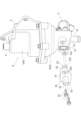
- FIG. 2 is a perspective view showing the gas-liquid separator and the heating member and holder in an assembled state.
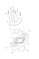
- FIG. 2 is an exploded perspective view of a heating member, a heating element, and a holder.
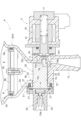
- FIG. 2 is a cross-sectional view of the lower part of the gas-liquid separator in a state where the on-off valve is closed.
- FIG. 2 is a sectional view of the lower part of the gas-liquid separator with the on-off valve open.
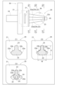
- 1 is a diagram showing a list of a heating element and cross sections of the heating element at locations indicated by a plurality of cross-section indicating lines.
- FIG. 3 is a side view showing a heating element of another embodiment (a).
- Figure 1 shows a fuel cell FC mounted on a fuel cell vehicle (FCV) and a gas-liquid separation system that separates water contained in anode off-gas (an example of water-containing gas) discharged from the anode side of the fuel cell FC.
- FCV fuel cell vehicle
- Device A is shown.
- a fuel cell FC generates electricity through an electrochemical reaction by supplying hydrogen gas as a fuel gas to the anode side and supplying air containing oxygen as an oxidizing gas to the cathode side. Only the anode side of the fuel cell FC is shown.
- the anode off-gas contains unreacted hydrogen gas
- the gas-liquid separator A guides the anode off-gas supplied from the introduction section 3 to the gas-liquid separation section 5, where it is separated from the anode off-gas.
- the water is separated, the separated water is stored in the water storage section 7, and the dry anode off-gas from which the water has been separated is sent out from the derivation section 4 to the reduction path L3.
- the anode off-gas thus sent to the reduction path L3 is supplied from the supply path L1 to the anode side of the fuel cell FC by the circulation pump P in the flow path of the reduction path L3, and unreacted hydrogen is used for power generation. .
- the gas-liquid separator A has a housing H consisting of an upper housing 1 and a lower housing 2, and the upper housing 1 and the lower housing 2 are connected by connecting their respective flanges to each other. and one are integrated to form a housing H having an internal space.
- the upper housing 1 is provided with a cylindrical introduction part 3 and a cylindrical outlet part 4 at the upper position, and is provided with a gas-liquid separation part 5 for separating water from the anode off-gas (water-containing gas) inside.
- the gas-liquid separation section 5 includes a plurality of vertical plate-shaped collision walls 5a that separate water by colliding with the anode off-gas supplied from the introduction section 3. Further, the dry anode off-gas that has passed through the gas-liquid separation section 5 is discharged from the outlet section 4.
- the lower housing 2 includes an open space 6 that allows the water separated by the gas-liquid separation section 5 to fall, a water storage section 7 that stores the water that has fallen through the open space 6, and an upper side of the water storage section 7 that stores the water.
- a filter unit 8 is provided to remove dust and the like contained in the filter.
- the lower portion of the lower housing 2 has a plurality of funnel-shaped inner surfaces 2a that taper downward, and the filter unit 8 is disposed at a position adjacent to the upper side of the funnel-shaped inner surface 2a at the lowest end. be done. Further, a cylindrical inner surface 2b that is circular in plan view is formed at a position continuous to the lower side of the funnel-shaped inner surface 2a at the lowest end.
- a water storage section 7 is constituted by a space surrounded by the funnel-shaped inner surface 2a at the lowermost end and a space surrounded by the cylindrical inner surface 2b. Note that the water storage portion 7 is not limited to a space that is circular in plan view, but may be rectangular, elliptical, or polygonal in plan view.
- the filter unit 8 includes a filter material 8b on the inner peripheral side of an annular frame 8a, and is fixed at the center to the support portion of the lower housing 2 with screws 8c. Thereby, dust contained in the water flowing into the water storage section 7 is removed by the filter material 8b.
- a block-shaped portion 10 is integrally formed at the lower end of the lower housing 2, and the water storage portion 7 described above is formed in this block-shaped portion 10.
- a concave portion 10a is formed in the block-shaped portion 10 in a horizontal position at a position communicating with the storage space of the water storage portion 7, and is recessed outward in the radial direction of the water storage portion 7 when viewed from above.
- a discharge hole path 11 is formed as a small-diameter orifice for laterally sending water stored in the water storage portion 7.
- the block-shaped portion 10 is formed with a cylindrical discharge portion 12 that communicates with the discharge hole passage 11 via the intra-block flow passage 10b and discharges water from the discharge hole passage 11 downward. Further, this block-shaped portion 10 is provided with an electromagnetic on-off valve V that controls the flow of water from the discharge hole path 11 to the discharge portion 12 .
- a heating member 20 is provided at the bottom of the water storage section 7 in a region where the water stored in the water storage section 7 flows into the discharge hole path 11.
- the heating member 20 is made of a material with high thermal conductivity, for example, an aluminum material.
- a heating element F is provided outside the water storage section 7 (outside the block-shaped section 10), which generates heat when energized and transmits the heat to the heating member 20.
- a through-hole portion 10c communicating with the space of the water storage portion 7 is formed on the opposite side of the block-shaped portion 10 from the discharge hole path 11 across the space of the water storage portion 7, and the heating member 20 is connected to the through-hole portion 10c. It is placed in the inserted state.
- the heating member 20 has a plate-shaped portion 21 integrally formed on the base end side, and a block-shaped portion is formed by a holder 30 disposed at a position covering the plate-shaped portion 21 and the heating element F. It is fixed at 10. The specific shape and fixing form of this heating member 20 will be described later.
- the discharge hole passage 11 is formed at a slightly higher position than the bottom wall 7a of the water storage portion 7, and a concave portion 10a is formed coaxially with this discharge hole passage 11.
- the discharge hole passage 11 is formed in a horizontal position so that the inner end communicates with the space of the water storage part 7 and the outer end communicates with the outside from one end of the block-shaped part 10. There is. Note that the end of the discharge hole path 11 on the discharge side opens into a truncated conical protrusion 10T.
- the discharge hole passage 11 and the discharge part 12 communicate with each other via the intra-block flow passage 10b of the block-shaped part 10, and by opening the on-off valve V, water from the discharge hole passage 11 flows into the block. It flows through the passage 10b to the discharge section 12 and is discharged.
- the on-off valve V includes a plunger 15 made of a magnetic material such as iron, an electromagnetic solenoid 16 disposed in an area surrounding the plunger 15, and an electromagnetic solenoid 16 that urges the plunger 15 in the projecting direction. It includes a spring 17 and a valve body 18 made of a membrane-like material such as rubber, which is disposed at a position to close the downstream end of the discharge hole path 11 and can be flexibly deformed between a closed position and an open position. ing.
- the heating member 20 is inserted into the bottom of the water storage portion 7 from the outside (outside the block-shaped portion 10 of the lower housing 2) with respect to the through-hole portion 10c.
- a heating element F is disposed on the outer surface of a plate-shaped portion 21 integrally formed on the base end side of the heating member 20, and a holder 30 is disposed at a position covering them.
- the heating member 20 and the holder 30 are fixed to the block-shaped portion 10 of the lower housing 2 with a plurality of bolts 34.
- the heating element F is placed in contact with the outer surface of the plate-shaped portion 21 (on the left side in FIGS. 4 and 5), and the heat generated by the heating element F is transmitted to the heating member 20.
- the heating element F is a PTC (Positive Temperature Coefficient) heater whose electrical resistance increases as the temperature rises.
- the heating member 20 is made of a material with high thermal conductivity, such as aluminum, and includes a plate-shaped portion 21, a heating main body portion 22 (an example of a main body portion), and a vertical wall portion 23 (an example of an upper wall portion). are integrally formed.
- the plate-shaped portion 21 is formed into a flat plate shape, and the heating main body portion 22 and the vertical wall portion 23 are integrally extended in a direction perpendicular to the plate surface of the plate-shaped portion 21 .
- the vertical wall portion 23 is formed so that the width in the lateral direction becomes slightly narrower as the tip approaches the discharge hole path 11 in plan view, and the height in side view becomes smaller. It is formed with a constant thickness in the direction.
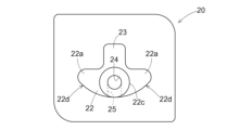
- the heating main body portion 22 has a tapered shape that becomes thinner toward the distal end closer to the discharge hole path 11 along the extension direction in a plan view. In the region from near the center of the heating body part 22 to the tip side, at least a part of the heating body part 22 has a length in the vertical direction with respect to the maximum width W in the horizontal direction (maximum horizontal width of the heating body part 22).
- X (the vertical thickness of the heating member 20) is set to be large (see C2 in FIG. 6).
- the heating member 20, the heating element F, and the holder 30 are shown in an exploded state in a plan view.
- the cylindrical inner surface 2b of the water storage portion 7 formed in the lower housing 2 is shown with a two-dot chain line, so that the positional relationship between the heating member 20 and the water storage portion 7 in a plan view is shown. It shows.
- cross sections corresponding to the cross-section designation lines C1, C2, and C3 in the heating member 20 shown in the upper row are shown as C1 and C2 in the middle row, and as C3 in the lower row.
- the heating member 20 is fixed to the lower housing 2, and a portion including the heating main body portion 22 and the vertical wall portion 23 is disposed inside the water storage portion 7. As shown in the cross-sectional view of C2 in FIG. The dimensional relationship is set so that the length X becomes larger. The size relationship between the maximum width W and the length X does not hold true in all regions of the heating main body portion 22 and the vertical wall portion 23, but only in a portion thereof.
- the heating member 20 has wing-shaped portions 22a formed on the left and right portions of the heating main body portion 22, and a slope that slopes downward toward the outer side in the lateral direction on the upper surface of the left and right wing-shaped portions 22a.
- a surface 22b is formed.
- the cylindrical portion 22c extends from the tip of the heating body 22 in the direction in which the heating body 22 protrudes (extends in the opposite direction of the plate-shaped portion 21). is formed.
- a main discharge hole 24 is formed in this cylindrical portion 22c, and an introduction hole 25 communicating with the main discharge hole 24 is formed in the lower surface of the heating main body portion 22.
- the inner diameter of the main discharge hole 24 is larger than the inner diameter of the discharge hole passage 11 .
- the heating member 20 is placed in the lower housing 2 at a position where the cylindrical portion 22c of the heating main body portion 22 fits into the recessed portion 10a. Further, the end of the vertical wall portion 23 in the opposite direction from the plate-like portion 21 is arranged at a position close to the discharge hole path 11 . In this arrangement of the heating member 20, the main discharge hole 24 and the discharge hole path 11 are coaxial. Further, the main discharge hole 24 is formed in a region extending a predetermined distance from the tip of the heating main body portion 22 toward the plate-shaped portion 21, and the introduction hole 25 communicates with the main discharge hole 24.
- a gap shown in FIGS. 4 and 5 is formed between the lower surface of the heating main body part 22 and the bottom wall 7a of the water storage part 7. This gap is set to such a thickness that even if the water is frozen, by reducing the thickness of the frozen part, it can be quickly thawed by the heat applied from the heating member 20, and the water can flow. ing.
- the holder 30 is made of an insulating resin material and has a cover portion 31, a pair of connecting portions 32, and a connector portion 33 integrally formed.
- the cover part 31 is configured to accommodate the plate-shaped part 21 of the heating member 20 and to be able to come into contact with the outer surface of the block-shaped part 10 .
- the connecting portion 32 is integrally formed on the outer edge of the cover portion 31, and has a bolt insertion hole 32a formed therein.
- the connector portion 33 includes a pair of electrodes 33a inside a cylindrical connector space.
- the heating member 20 when the heating member 20 is attached to the lower housing 2, the heating member 20 is inserted into the internal space of the water storage portion 7 from the through hole portion 10c of the block-shaped portion 10, as described above.
- the heating element F is arranged on the outer surface of the plate-shaped part 21 of the heating member 20, the cover part 31 is arranged so as to overlap the plate-shaped part 21 and the heating element F, and the bolt 34 is inserted into the bolt insertion hole 32a of the connecting part 32.
- the holder 30 is fixed by being inserted therethrough and screwed into the female threaded portion of the block-shaped portion 10 .
- a ring of rubber or resin is formed between the outer surface of the block-shaped part 10 and the plate-shaped part 21, and between the plate-shaped part 21 and the cover part 31.
- a seal body 27 is arranged.
- the heating element F is brought into close contact with the outer surface of the plate-shaped portion 21, and a conductive portion for supplying current to the heating element F from the electrode 33a of the connector portion 33 is formed.
- the fuel cell vehicle includes a control unit that controls the on-off valve V and controls the current supplied to the heating element F.
- This control section calculates the amount of water generated by power generation from the amount of power generated by the fuel cell during driving, estimates the amount of water stored in the water storage section 7, and every time the estimated amount of water reaches the set amount.
- opening the on-off valve V for a set time the water in the water storage section 7 is controlled to be discharged from the discharge hole path 11.
- control mode instead of such a control mode, a water level sensor that detects the water surface position is provided in order to measure the amount of water stored in the water storage section 7, and each time the water level detected by this water level sensor reaches a set value, Alternatively, the control mode may be set so that the on-off valve V is opened to discharge the water stored in the water storage section 7.
- the control unit is configured to prevent heat generation before starting to drive. Freezing is eliminated by supplying current to the body F to raise the temperature of the heating member 20. In order to eliminate freezing in this way, scavenging is performed by opening the on-off valve V and setting a predetermined air stoichiometric ratio in the fuel cell FC to operate (generate power).
- the temperature of the heating member 20 increases by supplying current to the heating element F, thereby increasing the temperature of the space between the lower surface of the heating main body 22 and the bottom wall 7a of the water storage section 7. , the temperature of the outer surface of the heating main body portion 22 or the vertical wall portion 23 is increased. This will thaw the ice if these parts are frozen, increase the temperature of the water if the temperature has dropped even if these parts do not freeze, and allow the thawed water to drain into the drain hole. It will be discharged from path 11.
- the heating member 20 when installing the heating member 20, the heating member 20 is inserted from the outside into the through hole 10c of the block-shaped part 10 of the lower housing 2, and the heating element F is arranged on the outer surface of the plate-shaped part 21.
- the heating member 20 can be easily attached and maintenance is not required.
- the heating element F since the heating element F is placed outside the lower housing 2, the problem of water coming into contact with the heating element F does not occur, and the configuration for electrical insulation is simplified, allowing for leakage. It will not cause short circuit or short circuit.
- the heating member 20 has a heating main body portion 22 and a vertical wall portion 23 that are integrally formed and are disposed inside the space of the water storage portion 7.
- the wide outer surface of the casing is brought into contact with water to enable efficient thawing.
- the vertical wall portion 23 allows the ice to be thawed even when the water storage portion 7 is frozen at a relatively high water level.
- a gap is formed between the lower surface of the heating main body part 22 and the bottom wall 7a of the water storage part 7, a flow of water is created in this gap, and a part of the water in this gap is transferred from the introduction hole 25.
- the temperature of the water flowing into the main discharge hole 24 can be increased.
- the heating member 20 is arranged such that a cylindrical portion 22c is fitted into the recessed portion 10a, and this cylindrical portion 22c is close to the discharge hole passage 11 formed in an orifice shape. Therefore, even if the discharge hole passage 11 is frozen, it can be thawed by the heat from the cylindrical portion 22c.
- a main discharge hole 24 is arranged in the cylindrical portion 22c coaxially with the discharge hole path 11, and in order to supply water to the main discharge hole 24 from the introduction hole 25, water is heated by the heating member 20. The water is sent out from the main discharge hole 24, and the discharge hole path 11 can be thawed efficiently.
- the heating member 20 forms a pair of wing-shaped parts 22a that expand outward on both sides in the lateral direction with the lateral center as a reference at the lower part of the heating main body part 22,
- the pair of wing-like parts 22a are formed so that the width decreases toward the tip side (the side where the cylindrical part 22c is located), so that the water in the water storage part 7 can smoothly flow into the discharge hole path 11. becomes possible.
- the lower surface of the wing-shaped portion 22a may include a U-shaped inclined surface 22d that slopes upward toward the outer side in the lateral direction.
- the upper surface of the wing-shaped portion 22a may be in a horizontal position, or the outer side in the width direction may be in an upwardly raised position. That is, the shape of the wing-shaped portion 22a may be any shape as long as a gap is formed between the lower surface of the heating main body portion 22 and the bottom wall 7a of the water storage portion 7.
- a portion of the heating member 20 may not have a fixed cross-sectional shape, such as a trapezoid or a rectangle, so that the maximum width in the horizontal direction is greater than the length in the vertical direction. Further, in order to increase the surface area of the heating member 20 and improve the efficiency of heat exchange with water, a groove-like portion or an uneven surface may be formed on the surface. Furthermore, all of the heating members 20 may be configured such that the maximum width in the horizontal direction is larger than the length in the vertical direction.
- Characteristic configurations of the gas-liquid separator (A) according to the present disclosure include a housing (H) to which water-containing gas is supplied, and a gas-liquid separator disposed above the housing (H) to separate water from the water-containing gas. part (5), a water storage part (7) which is arranged at the lower part of the housing (H) and stores water separated from the water-containing gas by the gas-liquid separation part (5), and a water storage part (7) of the housing (H).
- a discharge hole path (11) is disposed at the bottom and discharges the water sent from the water storage section (7) to the outside of the housing (H), and a discharge hole path (11) that protrudes into the water storage section (7) and discharges water sent from the water storage section (7) to the outside of the housing (H).
- the heating member (20) has a heating member (20) whose temperature increases due to the heat transferred from the heating element (F) which generates heat when energized. 7)
- the main body part (22) protrudes toward the discharge hole path (11) at the bottom of the water storage part (7), and the upper part protrudes upward from the main body part (22). The point is that it has a wall portion (23).
- the temperature rise of the heating member (20) causes the water in the water storage section (7) to flow into the discharge hole path (11) at the bottom of the water storage section (7). Thawing can be achieved by applying heat directly to the frozen portion of the flowing region.
- the heating member (20) has a main body (22) and an upper wall (23) projecting upward from the main body (22), water flowing into the water storage part (7) is transmitted.
- the temperature of the water storage part (7) is raised by bringing the area with a large thermal area (mainly the upper wall part (23)) into contact with each other, and even if the water level freezing in the water storage part (7) is relatively high, freezing can be removed. .
- a gas-liquid separator (A) has been constructed which, although having a simple structure, can eliminate freezing at the bottom of the gas-liquid separator (A) and quickly discharge water from the bottom.
- the upper wall portion (23) extends from the position where the heating element (F) is provided to a position close to the discharge hole path (11). It is okay to exist.
- the end of the upper wall (23) in the extending direction is in a positional relationship close to the discharge hole passage (11), and the heat transferred from this end causes the heat to stay in the vicinity of the discharge hole passage (11). Allows ice to thaw.
- the heating member (20) has a length (X) in the vertical direction on the side of the discharge hole path (11). It may be larger than the maximum width (W) in the direction.
- the length (X) in the vertical direction of the heating member (20) is larger than the maximum width (W) in the horizontal direction on the side of the discharge hole passage (11), It becomes possible to secure an area with a large heat transfer area for the water flowing into the area. As a result, not only the storage capacity of the water storage section (7) becomes large and the device becomes more compact, but also the temperature of the water storage section (7) can be quickly raised to eliminate freezing.
- the main body (22) has a main body (22) on both sides in the lateral direction based on the lateral center. 22) may be provided with a wing-shaped portion (22a) whose width decreases from the base end to which the air conditioner 22) is fixed toward the distal end close to the discharge hole path (11).
- the discharge hole path (11) can be thawed by heat from the wide surface of the wing-shaped portion (22a). do.
- the width of the wing-shaped portion (22a) decreases as the tip approaches the discharge hole passage (11)
- the thermal conductivity improves as the tip approaches, making it possible to effectively defrost the discharge hole passage (11). Not only is this possible, but when the water heated by the heating member (20) flows into the discharge hole path (11), the resistance acting on the water from the wing-shaped portion (22a) is reduced to enable smooth flow. .
- the upper surface of the wing-shaped portion (22a) may be inclined downward toward the outer side in the lateral direction.
- the water flowing into the water storage part (7) flows outward on the upper surface of the wing part (22a), thereby reducing the resistance acting on the water from the wing part (22a) and making it possible to flow without stagnation.
- the temperature of the heating member (20) is raised in a state where the water storage portion (7) is frozen, rapid thawing is achieved by transmitting heat from the wide surface of the wing-shaped portion (22a).
- the lower surface of the wing-shaped portion (22a) may be inclined upward toward the outer side in the lateral direction.
- the present disclosure can be used in a gas-liquid separator.
- Gas-liquid separation section 7 Water storage section 11 Discharge hole path 20 Heating member 22 Heating main body section (main body section) 22a Wing-shaped portion 23 Vertical wall portion (upper wall portion) A Gas-liquid separator F Heating element H Housing W Width X Thickness
Landscapes
- Chemical & Material Sciences (AREA)
- Chemical Kinetics & Catalysis (AREA)
- Life Sciences & Earth Sciences (AREA)
- Engineering & Computer Science (AREA)
- Manufacturing & Machinery (AREA)
- Sustainable Development (AREA)
- Sustainable Energy (AREA)
- Electrochemistry (AREA)
- General Chemical & Material Sciences (AREA)
- Fuel Cell (AREA)
Abstract
Description
〔基本構成〕
図1には、燃料電池車(FCV)に搭載される燃料電池FC、及び、この燃料電池FCのアノード側から排出されるアノードオフガス(含水ガスの一例)に含まれる水を分離する気液分離器Aが示されている。
図1、図2に示すように、気液分離器Aは、上部ハウジング1と下部ハウジング2とで成るハウジングHを有し、夫々のフランジ部を互いに連結することによって上部ハウジング1と下部ハウジング2と一が体化され、内部空間を有するハウジングHが構成される。
図4、図5に示すように、開閉弁Vは、鉄材等の磁性体で成るプランジャ15と、このプランジャ15を取り囲む領域に配置された電磁ソレノイド16と、プランジャ15を突出方向に付勢するスプリング17と、排出孔路11の下流側の端部を閉塞する位置に配置され、閉塞位置と開放位置との間で柔軟に変形し得るゴム等の膜状素材から成る弁体18とを備えている。
気液分離器Aは、低温環境において燃料電池の発電を停止して燃料電池車を駐車した場合に、貯水部7から排出孔路11に亘る領域に残留する水が凍結することもある。また、気液分離器Aは、低温の環境で燃料電池車を走行させる状況において貯水部7の水が凍結することもある。このような凍結を解消するため、図1、図4、図5に示すように、加熱部材20を貯水部7の底部に収容する形態で備えている。
図面には示していないが、燃料電池車は、開閉弁Vを制御し、発熱体Fに供給する電流を制御する制御部を備えている。この制御部は、走行時における燃料電池での発電量から発電に伴って生成される水量を演算によって求め、貯水部7に貯留される水量を推定し、推定した水量が設定量に達する毎に、設定された時間だけ開閉弁Vを開放することで、貯水部7の水を排出孔路11から排出する制御を行う。
このように、加熱部材20を装着する場合には、下部ハウジング2のブロック状部10の貫通孔部10cに外部から加熱部材20を挿入し、プレート状部21の外面に発熱体Fを配置し、ホルダ30をブロック状部10の外面に固定することにより、加熱部材20の装着が完了する。このため、加熱部材20の装着が容易でメンテナンスに手間が掛からない。また、この構成では、発熱体Fが下部ハウジング2の外部に配置されるため、発熱体Fに水が接触する不都合を招くことがなく、電気的な絶縁を行うための構成が簡素化し、漏電や短絡を招くこともない。
本開示は、上記した実施形態以外に以下のように構成しても良い(実施形態と同じ機能を有するものには、実施形態と共通の番号、符号を付している)。
7 貯水部
11 排出孔路
20 加熱部材
22 加熱本体部(本体部)
22a 翼状部
23 縦壁部(上壁部)
A 気液分離器
F 発熱体
H ハウジング
W 幅
X 厚み
Claims (6)
- 含水ガスが供給されるハウジングと、
前記ハウジングの上部に配置され前記含水ガスから水を分離する気液分離部と、
前記ハウジングの下部に配置され前記気液分離部によって前記含水ガスから分離した水を貯留する貯水部と、
前記ハウジングの前記貯水部の下部に配置され、前記貯水部より送られた前記水を前記ハウジングの外部に排出する排出孔路と、
前記貯水部の中へ突出し、前記水が前記排出孔路に流れる領域に配置され、通電により発熱する発熱体から伝えられる熱により温度が上昇する加熱部材と備え、
前記加熱部材は、前記発熱体が前記貯水部よりも外部に配置された状態で、前記貯水部の底部で前記排出孔路の側へと突出する本体部と、当該本体部から上方へ突出する上壁部とを有している気液分離器。 - 前記上壁部は、前記発熱体が設けられた位置から前記排出孔路に近接する位置まで延在している請求項1に記載の気液分離器。
- 前記加熱部材は、前記排出孔路の側において、縦方向の長さが横方向の最大幅に対して大きい請求項1又は2に記載の気液分離器。
- 前記本体部は、横方向の中央を基準に前記横方向の両側において前記本体部が固定される基端から前記排出孔路に近接する先端に向けて横幅が縮小する翼状部を備えている請求項1から3のいずれか一項に記載の気液分離器。
- 前記翼状部の上面が、前記横方向の外側ほど下側に向けて傾斜する姿勢である請求項4に記載の気液分離器。
- 前記翼状部の下面が、前記横方向の外側ほど上側に向けて傾斜する姿勢である請求項4に記載の気液分離器。
Priority Applications (2)
| Application Number | Priority Date | Filing Date | Title |
|---|---|---|---|
| CN202380064938.7A CN119866555A (zh) | 2022-09-15 | 2023-08-25 | 气液分离器 |
| EP23865234.1A EP4589697A4 (en) | 2022-09-15 | 2023-08-25 | GAS-LIQUID SEPARATOR |
Applications Claiming Priority (2)
| Application Number | Priority Date | Filing Date | Title |
|---|---|---|---|
| JP2022146771A JP7783560B2 (ja) | 2022-09-15 | 2022-09-15 | 気液分離器 |
| JP2022-146771 | 2022-09-15 |
Publications (1)
| Publication Number | Publication Date |
|---|---|
| WO2024057877A1 true WO2024057877A1 (ja) | 2024-03-21 |
Family
ID=90274970
Family Applications (1)
| Application Number | Title | Priority Date | Filing Date |
|---|---|---|---|
| PCT/JP2023/030675 Ceased WO2024057877A1 (ja) | 2022-09-15 | 2023-08-25 | 気液分離器 |
Country Status (4)
| Country | Link |
|---|---|
| EP (1) | EP4589697A4 (ja) |
| JP (1) | JP7783560B2 (ja) |
| CN (1) | CN119866555A (ja) |
| WO (1) | WO2024057877A1 (ja) |
Families Citing this family (1)
| Publication number | Priority date | Publication date | Assignee | Title |
|---|---|---|---|---|
| JP2026044566A (ja) * | 2024-08-30 | 2026-03-12 | ヤンマーホールディングス株式会社 | 燃料電池システムおよびモノジェネレーション装置 |
Citations (5)
| Publication number | Priority date | Publication date | Assignee | Title |
|---|---|---|---|---|
| JP2005005228A (ja) | 2003-06-16 | 2005-01-06 | Toyota Motor Corp | 燃料電池システム |
| JP2019096448A (ja) * | 2017-11-22 | 2019-06-20 | 本田技研工業株式会社 | 燃料電池システム及び燃料電池システムの制御方法 |
| JP2019139935A (ja) | 2018-02-09 | 2019-08-22 | 本田技研工業株式会社 | 燃料電池システム |
| JP2019149339A (ja) | 2018-02-28 | 2019-09-05 | 本田技研工業株式会社 | 燃料電池システム |
| JP2022157050A (ja) * | 2021-03-31 | 2022-10-14 | 本田技研工業株式会社 | 燃料電池システム、燃料電池システムの制御方法、およびプログラム |
Family Cites Families (1)
| Publication number | Priority date | Publication date | Assignee | Title |
|---|---|---|---|---|
| CN104302878B (zh) * | 2012-02-27 | 2020-03-13 | 纳博特斯克汽车零部件有限公司 | 具备压缩机、空气干燥器以及油分离器的系统 |
-
2022
- 2022-09-15 JP JP2022146771A patent/JP7783560B2/ja active Active
-
2023
- 2023-08-25 EP EP23865234.1A patent/EP4589697A4/en active Pending
- 2023-08-25 WO PCT/JP2023/030675 patent/WO2024057877A1/ja not_active Ceased
- 2023-08-25 CN CN202380064938.7A patent/CN119866555A/zh active Pending
Patent Citations (5)
| Publication number | Priority date | Publication date | Assignee | Title |
|---|---|---|---|---|
| JP2005005228A (ja) | 2003-06-16 | 2005-01-06 | Toyota Motor Corp | 燃料電池システム |
| JP2019096448A (ja) * | 2017-11-22 | 2019-06-20 | 本田技研工業株式会社 | 燃料電池システム及び燃料電池システムの制御方法 |
| JP2019139935A (ja) | 2018-02-09 | 2019-08-22 | 本田技研工業株式会社 | 燃料電池システム |
| JP2019149339A (ja) | 2018-02-28 | 2019-09-05 | 本田技研工業株式会社 | 燃料電池システム |
| JP2022157050A (ja) * | 2021-03-31 | 2022-10-14 | 本田技研工業株式会社 | 燃料電池システム、燃料電池システムの制御方法、およびプログラム |
Non-Patent Citations (1)
| Title |
|---|
| See also references of EP4589697A4 |
Also Published As
| Publication number | Publication date |
|---|---|
| EP4589697A1 (en) | 2025-07-23 |
| CN119866555A (zh) | 2025-04-22 |
| EP4589697A4 (en) | 2025-11-05 |
| JP2024042211A (ja) | 2024-03-28 |
| JP7783560B2 (ja) | 2025-12-10 |
Similar Documents
| Publication | Publication Date | Title |
|---|---|---|
| CN100362686C (zh) | 燃料电池冷却系统及控制燃料电池中冷却液的循环的方法 | |
| US11398633B2 (en) | Coolant storage tank | |
| US20090233158A1 (en) | Electric power supply system | |
| US20100112404A1 (en) | Fuel cell system | |
| JP2006331956A (ja) | 車両用の電源装置 | |
| JP7075780B2 (ja) | 燃料電池システム | |
| JP5262183B2 (ja) | 燃料電池システム | |
| KR20120084712A (ko) | 전기화학 에너지 저장장치 및 전기화학 에너지 저장장치를 냉각 또는 가열하기 위한 방법 | |
| WO2024057877A1 (ja) | 気液分離器 | |
| JP4595314B2 (ja) | 燃料電池システム | |
| JP4761107B2 (ja) | 燃料電池スタック | |
| KR100527958B1 (ko) | 냉시동성을 개선한 연료전지 시스템과 그 제어방법 | |
| CN111900436B (zh) | 一种燃料电池供氢系统及燃料电池系统 | |
| JP2005327665A (ja) | 気液分離システム | |
| US11362346B2 (en) | Fuel cell system | |
| JP2002246052A (ja) | 燃料電池装置及びその起動方法 | |
| JP7797828B2 (ja) | 気液分離器 | |
| CN111911709A (zh) | 阀门 | |
| JP2011000922A (ja) | 燃料電池搭載車両の燃料タンク温度管理装置 | |
| KR101090716B1 (ko) | 연료전지 차량용 히터 겸용 리저버 | |
| US20260115654A1 (en) | Gas-liquid separation apparatus | |
| JP7797829B2 (ja) | 気液分離器 | |
| JP5086941B2 (ja) | 燃料電池システム | |
| JP2006147414A (ja) | 燃料電池システム | |
| JP7562436B2 (ja) | 燃料電池システム |
Legal Events
| Date | Code | Title | Description |
|---|---|---|---|
| 121 | Ep: the epo has been informed by wipo that ep was designated in this application |
Ref document number: 23865234 Country of ref document: EP Kind code of ref document: A1 |
|
| WWE | Wipo information: entry into national phase |
Ref document number: 202380064938.7 Country of ref document: CN |
|
| WWE | Wipo information: entry into national phase |
Ref document number: 2023865234 Country of ref document: EP |
|
| NENP | Non-entry into the national phase |
Ref country code: DE |
|
| ENP | Entry into the national phase |
Ref document number: 2023865234 Country of ref document: EP Effective date: 20250415 |
|
| WWP | Wipo information: published in national office |
Ref document number: 202380064938.7 Country of ref document: CN |
|
| WWP | Wipo information: published in national office |
Ref document number: 2023865234 Country of ref document: EP |