WO2024057925A1 - 非水電解質蓄電素子及び蓄電装置 - Google Patents
非水電解質蓄電素子及び蓄電装置 Download PDFInfo
- Publication number
- WO2024057925A1 WO2024057925A1 PCT/JP2023/031364 JP2023031364W WO2024057925A1 WO 2024057925 A1 WO2024057925 A1 WO 2024057925A1 JP 2023031364 W JP2023031364 W JP 2023031364W WO 2024057925 A1 WO2024057925 A1 WO 2024057925A1
- Authority
- WO
- WIPO (PCT)
- Prior art keywords
- active material
- electrode active
- positive electrode
- carbon
- negative electrode
- Prior art date
- Legal status (The legal status is an assumption and is not a legal conclusion. Google has not performed a legal analysis and makes no representation as to the accuracy of the status listed.)
- Ceased
Links
Images

Classifications
-
- H—ELECTRICITY
- H01—ELECTRIC ELEMENTS
- H01G—CAPACITORS; CAPACITORS, RECTIFIERS, DETECTORS, SWITCHING DEVICES, LIGHT-SENSITIVE OR TEMPERATURE-SENSITIVE DEVICES OF THE ELECTROLYTIC TYPE
- H01G11/00—Hybrid capacitors, i.e. capacitors having different positive and negative electrodes; Electric double-layer [EDL] capacitors; Processes for the manufacture thereof or of parts thereof
- H01G11/22—Electrodes
- H01G11/24—Electrodes characterised by structural features of the materials making up or comprised in the electrodes, e.g. form, surface area or porosity; characterised by the structural features of powders or particles used therefor
-
- H—ELECTRICITY
- H01—ELECTRIC ELEMENTS
- H01G—CAPACITORS; CAPACITORS, RECTIFIERS, DETECTORS, SWITCHING DEVICES, LIGHT-SENSITIVE OR TEMPERATURE-SENSITIVE DEVICES OF THE ELECTROLYTIC TYPE
- H01G11/00—Hybrid capacitors, i.e. capacitors having different positive and negative electrodes; Electric double-layer [EDL] capacitors; Processes for the manufacture thereof or of parts thereof
- H01G11/22—Electrodes
- H01G11/30—Electrodes characterised by their material
- H01G11/50—Electrodes characterised by their material specially adapted for lithium-ion capacitors, e.g. for lithium-doping or for intercalation
-
- H—ELECTRICITY
- H01—ELECTRIC ELEMENTS
- H01M—PROCESSES OR MEANS, e.g. BATTERIES, FOR THE DIRECT CONVERSION OF CHEMICAL ENERGY INTO ELECTRICAL ENERGY
- H01M10/00—Secondary cells; Manufacture thereof
- H01M10/05—Accumulators with non-aqueous electrolyte
- H01M10/052—Li-accumulators
- H01M10/0525—Rocking-chair batteries, i.e. batteries with lithium insertion or intercalation in both electrodes; Lithium-ion batteries
-
- H—ELECTRICITY
- H01—ELECTRIC ELEMENTS
- H01M—PROCESSES OR MEANS, e.g. BATTERIES, FOR THE DIRECT CONVERSION OF CHEMICAL ENERGY INTO ELECTRICAL ENERGY
- H01M4/00—Electrodes
- H01M4/02—Electrodes composed of, or comprising, active material
- H01M4/13—Electrodes for accumulators with non-aqueous electrolyte, e.g. for lithium-accumulators; Processes of manufacture thereof
- H01M4/133—Electrodes based on carbonaceous material, e.g. graphite-intercalation compounds or CFx
-
- H—ELECTRICITY
- H01—ELECTRIC ELEMENTS
- H01M—PROCESSES OR MEANS, e.g. BATTERIES, FOR THE DIRECT CONVERSION OF CHEMICAL ENERGY INTO ELECTRICAL ENERGY
- H01M4/00—Electrodes
- H01M4/02—Electrodes composed of, or comprising, active material
- H01M4/13—Electrodes for accumulators with non-aqueous electrolyte, e.g. for lithium-accumulators; Processes of manufacture thereof
- H01M4/136—Electrodes based on inorganic compounds other than oxides or hydroxides, e.g. sulfides, selenides, tellurides, halogenides or LiCoFy
-
- H—ELECTRICITY
- H01—ELECTRIC ELEMENTS
- H01M—PROCESSES OR MEANS, e.g. BATTERIES, FOR THE DIRECT CONVERSION OF CHEMICAL ENERGY INTO ELECTRICAL ENERGY
- H01M4/00—Electrodes
- H01M4/02—Electrodes composed of, or comprising, active material
- H01M4/36—Selection of substances as active materials, active masses, active liquids
- H01M4/362—Composites
- H01M4/366—Composites as layered products
-
- H—ELECTRICITY
- H01—ELECTRIC ELEMENTS
- H01M—PROCESSES OR MEANS, e.g. BATTERIES, FOR THE DIRECT CONVERSION OF CHEMICAL ENERGY INTO ELECTRICAL ENERGY
- H01M4/00—Electrodes
- H01M4/02—Electrodes composed of, or comprising, active material
- H01M4/36—Selection of substances as active materials, active masses, active liquids
- H01M4/58—Selection of substances as active materials, active masses, active liquids of inorganic compounds other than oxides or hydroxides, e.g. sulfides, selenides, tellurides, halogenides or LiCoFy; of polyanionic structures, e.g. phosphates, silicates or borates
- H01M4/5825—Oxygenated metallic salts or polyanionic structures, e.g. borates, phosphates, silicates, olivines
-
- H—ELECTRICITY
- H01—ELECTRIC ELEMENTS
- H01M—PROCESSES OR MEANS, e.g. BATTERIES, FOR THE DIRECT CONVERSION OF CHEMICAL ENERGY INTO ELECTRICAL ENERGY
- H01M4/00—Electrodes
- H01M4/02—Electrodes composed of, or comprising, active material
- H01M4/36—Selection of substances as active materials, active masses, active liquids
- H01M4/58—Selection of substances as active materials, active masses, active liquids of inorganic compounds other than oxides or hydroxides, e.g. sulfides, selenides, tellurides, halogenides or LiCoFy; of polyanionic structures, e.g. phosphates, silicates or borates
- H01M4/583—Carbonaceous material, e.g. graphite-intercalation compounds or CFx
- H01M4/587—Carbonaceous material, e.g. graphite-intercalation compounds or CFx for inserting or intercalating light metals
-
- H—ELECTRICITY
- H01—ELECTRIC ELEMENTS
- H01M—PROCESSES OR MEANS, e.g. BATTERIES, FOR THE DIRECT CONVERSION OF CHEMICAL ENERGY INTO ELECTRICAL ENERGY
- H01M4/00—Electrodes
- H01M4/02—Electrodes composed of, or comprising, active material
- H01M4/62—Selection of inactive substances as ingredients for active masses, e.g. binders, fillers
- H01M4/624—Electric conductive fillers
- H01M4/625—Carbon or graphite
-
- H—ELECTRICITY
- H01—ELECTRIC ELEMENTS
- H01G—CAPACITORS; CAPACITORS, RECTIFIERS, DETECTORS, SWITCHING DEVICES, LIGHT-SENSITIVE OR TEMPERATURE-SENSITIVE DEVICES OF THE ELECTROLYTIC TYPE
- H01G11/00—Hybrid capacitors, i.e. capacitors having different positive and negative electrodes; Electric double-layer [EDL] capacitors; Processes for the manufacture thereof or of parts thereof
- H01G11/04—Hybrid capacitors
- H01G11/06—Hybrid capacitors with one of the electrodes allowing ions to be reversibly doped thereinto, e.g. lithium ion capacitors [LIC]
-
- H—ELECTRICITY
- H01—ELECTRIC ELEMENTS
- H01M—PROCESSES OR MEANS, e.g. BATTERIES, FOR THE DIRECT CONVERSION OF CHEMICAL ENERGY INTO ELECTRICAL ENERGY
- H01M4/00—Electrodes
- H01M4/02—Electrodes composed of, or comprising, active material
- H01M2004/021—Physical characteristics, e.g. porosity, surface area
-
- H—ELECTRICITY
- H01—ELECTRIC ELEMENTS
- H01M—PROCESSES OR MEANS, e.g. BATTERIES, FOR THE DIRECT CONVERSION OF CHEMICAL ENERGY INTO ELECTRICAL ENERGY
- H01M4/00—Electrodes
- H01M4/02—Electrodes composed of, or comprising, active material
- H01M2004/026—Electrodes composed of, or comprising, active material characterised by the polarity
- H01M2004/027—Negative electrodes
-
- H—ELECTRICITY
- H01—ELECTRIC ELEMENTS
- H01M—PROCESSES OR MEANS, e.g. BATTERIES, FOR THE DIRECT CONVERSION OF CHEMICAL ENERGY INTO ELECTRICAL ENERGY
- H01M4/00—Electrodes
- H01M4/02—Electrodes composed of, or comprising, active material
- H01M2004/026—Electrodes composed of, or comprising, active material characterised by the polarity
- H01M2004/028—Positive electrodes
-
- Y—GENERAL TAGGING OF NEW TECHNOLOGICAL DEVELOPMENTS; GENERAL TAGGING OF CROSS-SECTIONAL TECHNOLOGIES SPANNING OVER SEVERAL SECTIONS OF THE IPC; TECHNICAL SUBJECTS COVERED BY FORMER USPC CROSS-REFERENCE ART COLLECTIONS [XRACs] AND DIGESTS
- Y02—TECHNOLOGIES OR APPLICATIONS FOR MITIGATION OR ADAPTATION AGAINST CLIMATE CHANGE
- Y02E—REDUCTION OF GREENHOUSE GAS [GHG] EMISSIONS, RELATED TO ENERGY GENERATION, TRANSMISSION OR DISTRIBUTION
- Y02E60/00—Enabling technologies; Technologies with a potential or indirect contribution to GHG emissions mitigation
- Y02E60/10—Energy storage using batteries
Definitions
- the present invention relates to a non-aqueous electrolyte power storage element and a power storage device.
- Non-aqueous electrolyte secondary batteries typified by lithium ion secondary batteries
- the nonaqueous electrolyte secondary battery generally has a pair of electrodes electrically isolated by a separator and a nonaqueous electrolyte interposed between the electrodes, and charge transport ions are exchanged between the two electrodes.
- the battery is configured to be charged and discharged by performing the following steps.
- Capacitors such as lithium ion capacitors and electric double layer capacitors are also widely used as non-aqueous electrolyte storage devices other than non-aqueous electrolyte secondary batteries.
- Patent Document 1 describes a lithium secondary battery using lithium iron phosphate as a positive electrode active material.
- a non-aqueous electrolyte storage element that uses a lithium transition metal compound having a polyanionic structure, such as lithium iron phosphate, as a positive electrode active material may have reduced output performance after charge/discharge cycles.
- the present invention has been made based on the above circumstances, and an object of the present invention is to provide a non-aqueous electrolyte power storage element and a power storage device that can suppress a decrease in output retention rate after a charge/discharge cycle.
- a non-aqueous electrolyte storage device includes a positive electrode having a carbon-coated positive electrode active material, a negative electrode having a negative electrode active material, and a non-aqueous electrolyte, wherein the carbon-coated positive electrode active material has a polyanion structure.
- the negative electrode active material contains a carbon material.
- a power storage device includes one or more power storage elements according to another aspect of the present invention, and includes two or more power storage elements.
- the non-aqueous electrolyte power storage element and power storage device can suppress a decrease in output maintenance rate after a charge/discharge cycle.
- FIG. 1 is a transparent perspective view showing one embodiment of a non-aqueous electrolyte storage element.
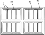
- FIG. 2 is a schematic diagram showing an embodiment of a power storage device configured by collecting a plurality of non-aqueous electrolyte power storage elements.
- a non-aqueous electrolyte electricity storage device includes a positive electrode having a carbon-coated positive electrode active material, a negative electrode having a negative electrode active material, and a non-aqueous electrolyte, wherein the carbon-coated positive electrode active material is a positive electrode active material containing a lithium transition metal compound having a polyanion structure; and a coating layer containing a carbon element and covering at least a portion of the positive electrode active material;
- the positive electrode active material has a BET specific surface area ratio of 0.40 or more and 0.80 or less, and the negative electrode active material contains a carbon material.
- the non-aqueous electrolyte storage element described in [1] above can suppress a decrease in output retention rate after charge/discharge cycles. Although the reason for this is not certain, the following reasons are assumed.
- the positive electrode has a positive electrode active material containing a lithium transition metal compound (such as lithium iron phosphate) having a polyanion structure.
- a lithium transition metal compound such as lithium iron phosphate
- the transition metal cations constituting the lithium-transition metal compound are easily eluted into the non-aqueous electrolyte, and by repeating charging and discharging cycles, the transition metal cations on the surface of the negative electrode active material are dissolved. The formation of a film may progress.
- this film may reduce the output performance after a charge/discharge cycle.
- the negative electrode active material is made of metallic lithium
- the metallic lithium is dissolved and precipitated by the charge/discharge reaction, so a film derived from the transition metal cations is formed on the surface of the negative electrode active material by repeating charge/discharge cycles. The progress is gradual, and the effect on the output performance of the coating is slight.
- the negative electrode active material contains a carbon material, the carbon material is not dissolved out due to the charge/discharge reaction, so the formation of a film derived from the transition metal cations on the surface of the negative electrode active material due to repeated charge/discharge cycles is slowed down.
- the positive electrode of the non-aqueous electrolyte storage element described in [1] above includes a carbon-coated positive electrode active material in which the positive electrode active material is covered with a coating layer containing a carbon element. Therefore, contact between the positive electrode active material and the nonaqueous electrolyte can be suppressed. Further, the ratio of the BET specific surface area of the positive electrode active material to the BET specific surface area of the carbon-coated positive electrode active material is within a certain range. Here, the ratio of the BET specific surface area of the positive electrode active material to the BET specific surface area of the carbon-coated positive electrode active material represents the degree of density of the coating layer.
- the appropriately dense coating layer covers the positive electrode active material. Therefore, even if the negative electrode active material contains a carbon material, the coating layer can effectively suppress the elution of the transition metal cation and the formation of the film on the surface of the negative electrode active material. Therefore, it is considered that a decrease in the output maintenance rate after the charge/discharge cycle is suppressed.
- the negative electrode active material may contain graphite, and the average particle diameter of the negative electrode active material may be 20 ⁇ m or less.
- the output performance of a nonaqueous electrolyte storage element can be improved.
- a lithium transition metal compound having a polyanion structure is used as the positive electrode active material, the formation of the above-mentioned film on the surface of the negative electrode active material may be accelerated.
- the elution of the transition metal cation can be suppressed by the coating layer that covers the positive electrode active material. Therefore, when the negative electrode active material contains graphite and the average particle diameter of the negative electrode active material is equal to or less than the above upper limit, the initial output can be improved while suppressing a decrease in the output retention rate after charge/discharge cycles. The effects of the present invention are significantly exhibited.
- the ratio may be 0.50 or more, and the average particle diameter of the negative electrode active material may be 5 ⁇ m or less.
- the initial output can be further improved.
- the ratio is equal to or higher than the lower limit, it is possible to more reliably suppress a decrease in the output maintenance rate after the charge/discharge cycle. Therefore, by making the ratio above the lower limit and the average particle diameter of the negative electrode active material below the upper limit, the initial output can be further improved while suppressing a decrease in the output retention rate after charge/discharge cycles. Can be done.
- average particle size refers to the particle size distribution measured by laser diffraction/scattering method on a diluted solution of a sample to be measured with a solvent, in accordance with JIS-Z-8825 (2013). , means the particle size (median diameter) at which the volume-based integrated distribution calculated in accordance with JIS-Z-8819-2 (2001) is 50% based on this particle size distribution.
- BET specific surface area refers to the method of immersing the sample to be measured in liquid nitrogen, supplying nitrogen gas to physically adsorb nitrogen molecules on the particle surface, and measuring the pressure and adsorption amount at that time.
- the nitrogen adsorption amount [m 2 ] for the sample is determined by a single point method.
- the value obtained by dividing the obtained nitrogen adsorption amount by the mass [g] of the sample is defined as the BET specific surface area [m 2 /g].
- the sample taken from the non-aqueous electrolyte storage element after initial charging and discharging is measured.
- a sample to be measured is collected according to the following procedure. First, the non-aqueous electrolyte storage element after initial charging and discharging is discharged at a constant current of 0.1 C to the discharge end voltage during normal use to bring it into a discharged state.
- the term "normal use” refers to a case where the non-aqueous electrolyte storage element is used under recommended or specified charge/discharge conditions for the non-aqueous electrolyte storage element.
- the discharged non-aqueous electrolyte storage element is disassembled, the positive electrode or negative electrode is taken out, and components (electrolyte, etc.) adhering to the positive electrode or negative electrode are thoroughly washed with dimethyl carbonate. Thereafter, the positive electrode or negative electrode is dried under reduced pressure at room temperature for 24 hours. Next, the powder of the positive electrode active material layer or the negative electrode active material layer is collected from the positive electrode or the negative electrode.
- Optional components such as a conductive agent mixed in the powder of the positive electrode active material layer or the negative electrode active material layer are removed using wind classification or the like, and a sample to be measured is collected.
- the process from dismantling the nonaqueous electrolyte storage element to collecting the sample to be measured is performed in an argon atmosphere with a dew point of -60°C or lower.
- the "BET specific surface area of the carbon-coated positive electrode active material” and the “BET specific surface area of the positive electrode active material” are determined by the following procedure. First, the non-aqueous electrolyte storage element is disassembled and the positive electrode taken out is washed and dried as described above, and then the BET specific surface area of the collected carbon-coated positive electrode active material is measured. Next, the coating layer is removed by baking the carbon-coated positive electrode active material at 350° C. for 4 hours in an air atmosphere. Thereafter, the BET specific surface area of the positive electrode active material from which the coating layer has been removed is measured.
- a power storage device includes one or more non-aqueous electrolyte power storage elements described in any one of [1] to [3] above, and the non-aqueous electrolyte power storage element Equipped with two or more.
- the power storage device according to [4] above includes one or more non-aqueous electrolyte power storage elements according to any one of [1] to [3] above, thereby suppressing a decrease in output maintenance rate after charge/discharge cycles. can do.
- each component (each component) used in each embodiment may be different from the name of each component (each component) used in the background art.
- a non-aqueous electrolyte storage device (hereinafter also simply referred to as a "power storage device") according to an embodiment of the present invention includes an electrode body having a positive electrode, a negative electrode, and a separator, a non-aqueous electrolyte, and the electrode body and the non-aqueous electrolyte.
- the electrode body is usually a laminated type in which a plurality of positive electrodes and a plurality of negative electrodes are laminated with a separator in between, or a wound type in which a positive electrode and a negative electrode are laminated and wound with a separator in between.
- the non-aqueous electrolyte exists in the positive electrode, negative electrode, and separator.
- a non-aqueous electrolyte storage element a non-aqueous electrolyte secondary battery (hereinafter also simply referred to as a "secondary battery”) will be described.
- the positive electrode includes a positive electrode base material and a positive electrode active material layer disposed on the positive electrode base material directly or via an intermediate layer.
- the positive electrode base material has electrical conductivity. Whether or not it has “conductivity” is determined using a volume resistivity of 10 ⁇ 2 ⁇ cm as a threshold value, which is measured in accordance with JIS-H-0505 (1975).
- the material of the positive electrode base material metals such as aluminum, titanium, tantalum, stainless steel, or alloys thereof are used. Among these, aluminum or aluminum alloy is preferred from the viewpoint of potential resistance, high conductivity, and cost.
- Examples of the positive electrode base material include foil, vapor deposited film, mesh, porous material, etc., and foil is preferable from the viewpoint of cost. Therefore, aluminum foil or aluminum alloy foil is preferable as the positive electrode base material. Examples of aluminum or aluminum alloy include A1085, A3003, A1N30, etc. specified in JIS-H-4000 (2014) or JIS-H-4160 (2006).
- the average thickness of the positive electrode base material is preferably 3 ⁇ m or more and 50 ⁇ m or less, more preferably 5 ⁇ m or more and 40 ⁇ m or less, even more preferably 8 ⁇ m or more and 30 ⁇ m or less, and particularly preferably 10 ⁇ m or more and 25 ⁇ m or less.
- the intermediate layer is a layer disposed between the positive electrode base material and the positive electrode active material layer.
- the intermediate layer reduces contact resistance between the positive electrode base material and the positive electrode active material layer by containing a conductive agent such as carbon particles.
- the structure of the intermediate layer is not particularly limited, and includes, for example, a binder and a conductive agent.
- the cathode active material layer includes a carbon-coated cathode active material.
- the positive electrode active material layer can contain optional components such as a conductive agent, a binder, a thickener, and a filler, as necessary.
- the carbon-coated positive electrode active material has a positive electrode active material and a coating layer (hereinafter also referred to as "carbon coating layer") that contains a carbon element and covers at least a portion of the positive electrode active material.
- the above-mentioned carbon-coated positive electrode active material is usually a granular material having particles of the positive electrode active material as cores.
- Examples of the method for producing the carbon-coated positive electrode active material include, for example, preparing a slurry by pulverizing a mixture of the positive electrode active material, an organic compound serving as a carbon source, etc., and a solvent using a bead mill, and then drying and heat-treating the mixture. It will be done.
- the above organic compounds include polyvinyl alcohol, polyvinylpyrrolidone, cellulose, starch, gelatin, carboxymethylcellulose, methylcellulose, hydroxymethylcellulose, hydroxyethylcellulose, polyacrylic acid, polystyrene sulfonic acid, polyacrylamide, polyvinyl acetate, glucose, fructose, galactose, Examples include mannose, maltose, sucrose, lactose, glycogen, pectin, alginic acid, glucomannan, chitin, hyaluronic acid, chondroitin, agarose, polyether, polyhydric alcohol, and the like.
- the polyhydric alcohol include polyethylene glycol, polypropylene glycol, polyglycerin, and glycerin.
- the positive electrode active material of the carbon-coated positive electrode active material contains a lithium transition metal compound having a polyanion structure.
- lithium transition metal compounds examples include LiFePO 4 , LiMnPO 4 , LiNiPO 4 , LiMn 0.5 Ni 0.5 PO 4 , LiCoPO 4 , Li 3 V 2 (PO 4 ). 3 , Li 2 MnSiO 4 , Li 2 FePO 4 F, Li 2 CoPO 4 F, Li 2 NiPO 4 F, and the like.
- compounds (phosphate compounds) containing phosphate ions (PO 4 3- ) are preferred, and lithium iron phosphate (LiFePO 4 ) is more preferred.
- the polyanion compound may be one in which some of the constituent atoms or polyanions are substituted with other atoms or other anion species. Generally, polyanionic compounds have low electrical conductivity, but the electrical conductivity can be improved by covering at least a portion with a carbon coating layer.
- the polyanion compounds may be used alone or in combination of two or more.
- the content of the lithium transition metal compound in the positive electrode active material of the carbon-coated positive electrode active material can be, for example, 95% by mass or more and 100% by mass or less. That is, the positive electrode active material of the carbon-coated positive electrode active material may consist essentially only of the above lithium transition metal compound.
- the content of the lithium transition metal compound in the carbon-coated positive electrode active material is preferably 90.0% by mass or more and 99.5% by mass or less, more preferably 92.0% by mass or more and 99.2% by mass or less, and 94% by mass. More preferably, it is 0% by mass or more and 99.0% by mass or less.
- the carbon coating layer of the carbon-coated positive electrode active material contains the carbon element as described above.
- the content of carbon element in the carbon coating layer can be, for example, 95% by mass or more and 100% by mass or less. That is, the carbon coating layer of the carbon-coated positive electrode active material may consist essentially only of carbon element.
- the carbon element in the carbon coating layer formed by the above-described procedure usually exists in the form of a mixture of highly crystalline carbon and low crystalline carbon.
- the lower limit of the content of the carbon element in the carbon-coated positive electrode active material is preferably 0.5% by mass, more preferably 0.7% by mass, and even more preferably 1.0% by mass.
- the upper limit of this content is preferably 3.0% by mass, more preferably 2.5% by mass, and even more preferably 2.0% by mass.
- the lower limit of the ratio of the BET specific surface area of the positive electrode active material to the BET specific surface area of the carbon-coated positive electrode active material is 0.40, preferably 0.50, and more preferably 0.60.
- the upper limit of the above ratio is 0.80, preferably 0.77, and more preferably 0.75.
- the ratio of the BET specific surface area of the positive electrode active material to the BET specific surface area of the carbon-coated positive electrode active material represents the degree of density of the carbon coating layer.
- a large ratio means that the BET specific surface area of the carbon-coated positive electrode active material is small and that the carbon-coated positive electrode active material has a relatively dense carbon coating layer.
- the ratio when the above ratio is small, it means that the BET specific surface area of the carbon-coated positive electrode active material is large and the carbon-coated positive electrode active material has a relatively rough carbon coating layer. For this reason, when the ratio is equal to or higher than the lower limit, a suitably dense carbon coating layer covers the positive electrode active material, thereby easily suppressing a decrease in the output retention rate after charge/discharge cycles. Moreover, when the ratio is equal to or less than the upper limit, it is easy to ensure the ionic conductivity of the positive electrode active material layer, and it is easy to make the charge/discharge reaction uniform.
- the lower limit of the BET specific surface area of the carbon-coated positive electrode active material is preferably 10.0 m 2 /g, more preferably 13.0 m 2 /g, and even more preferably 13.5 m 2 /g.
- the upper limit of the BET specific surface area of the carbon-coated positive electrode active material is preferably 15.0 m 2 /g, more preferably 14.0 m 2 /g, and even more preferably 13.8 m 2 /g.
- the BET specific surface area of the carbon-coated positive electrode active material is less than or equal to the above upper limit, it is easy to suppress a decrease in the output maintenance rate after charge/discharge cycles.
- the BET specific surface area of the carbon-coated cathode active material can be controlled by adjusting the BET specific surface area of the cathode active material and the BET specific surface area of the carbon coating layer in the carbon-coated cathode active material, etc., by the method described below. can.
- the lower limit of the BET specific surface area of the positive electrode active material in the carbon-coated positive electrode active material is preferably 4.0 m 2 /g, more preferably 5.0 m 2 /g, and even more preferably 5.5 m 2 /g.
- the upper limit of the BET specific surface area of the positive electrode active material is preferably 13 m 2 /g, more preferably 12 m 2 /g, and even more preferably 11 m 2 /g.
- the BET specific surface area of the positive electrode active material is less than or equal to the above upper limit, it is easy to suppress a decrease in the output retention rate after charge/discharge cycles.
- the BET specific surface area of the positive electrode active material can be controlled, for example, by adjusting the grinding time using a bead mill or the like in the method for producing the carbon-coated positive electrode active material described above.
- the lower limit of the difference in BET specific surface area between the carbon-coated cathode active material and the cathode active material is 1.0 m 2 /g. is preferable, 2.0 m 2 /g is more preferable, and 2.5 m 2 /g is even more preferable.
- the upper limit of the difference is preferably 9.0 m 2 /g, more preferably 8.0 m 2 /g, and even more preferably 7.0 m 2 /g. When the difference is equal to or greater than the lower limit, output performance can be easily improved.
- the difference is less than or equal to the upper limit, it is easy to suppress a decrease in the output maintenance rate after the charge/discharge cycle.
- the above difference is proportional to the BET specific surface area of the carbon coating layer in the carbon-coated positive electrode active material.
- the BET specific surface area of the carbon coating layer can be controlled, for example, by changing the carbon source, adjusting the heat treatment temperature and heat treatment time, etc. in the method for manufacturing the carbon-coated positive electrode active material described above.
- the positive electrode active material layer may contain a positive electrode active material other than the carbon-coated positive electrode active material.
- the other positive electrode active materials include a lithium transition metal composite oxide having an ⁇ -NaFeO 2 type crystal structure, a lithium transition metal composite oxide having a spinel type crystal structure, a polyanion compound having no carbon coating layer, Examples include chalcogen compounds and sulfur.
- lithium transition metal composite oxides having ⁇ -NaFeO type 2 crystal structure examples include Li[Li x Ni (1-x) ]O 2 (0 ⁇ x ⁇ 0.5), Li[Li x Ni ⁇ Co ( 1-x- ⁇ ) ]O 2 (0 ⁇ x ⁇ 0.5, 0 ⁇ 1, 0 ⁇ 1-x- ⁇ ), Li[Li x Co (1-x) ]O 2 (0 ⁇ x ⁇ 0.5 ), Li [ Li x Ni ⁇ Mn ⁇ Co (1-x- ⁇ - ⁇ ) ]O 2 (0 ⁇ x ⁇ 0.5, 0 ⁇ , 0 ⁇ , 0.5 ⁇ + ⁇ 1, 0 ⁇ 1-x- ⁇ - ⁇ ), Li[Li x Ni ⁇ Co ⁇ Al (1-x- ⁇ - ⁇ ) ]O 2 (0 ⁇ x ⁇ 0.5, 0 ⁇ , 0 ⁇ , 0.5 ⁇ + ⁇ 1, 0 ⁇ 1-x- ⁇ - ⁇ ).
- lithium transition metal composite oxides having a spinel crystal structure examples include Li x Mn 2 O 4 and Li x Ni ⁇ Mn (2- ⁇ ) O 4 .
- polyanion compounds without a carbon coating layer examples include LiFePO 4 , LiMnPO 4 , LiNiPO 4 , LiCoPO 4 , Li 3 V 2 (PO 4 ) 3 , Li 2 MnSiO 4 , Li 2 CoPO 4 F, and the like.
- chalcogen compounds include titanium disulfide, molybdenum disulfide, molybdenum dioxide, and the like. Atoms or polyanions in these materials may be partially substituted with atoms or anion species of other elements. The surfaces of these materials may be coated with a material other than the carbon coating layer. In the positive electrode active material layer, one type of these materials may be used alone, or two or more types may be used in combination.
- the carbon-coated positive electrode active material and other positive electrode active materials are particles (powder).
- the average particle diameter of the carbon-coated positive electrode active material is preferably, for example, 0.1 ⁇ m or more and 20 ⁇ m or less. By setting the average particle diameter of the carbon-coated positive electrode active material to be equal to or larger than the above lower limit, the carbon-coated positive electrode active material can be easily produced or handled. By setting the average particle diameter of the carbon-coated positive electrode active material to be equal to or less than the above upper limit, the ionic conductivity in the positive electrode active material layer is improved.
- a pulverizer, classifier, etc. are used to obtain powder with a predetermined particle size.
- the pulverization method include methods using a mortar, a ball mill, a sand mill, a vibrating ball mill, a planetary ball mill, a jet mill, a counter jet mill, a swirling jet mill, a sieve, and the like.
- wet pulverization in which water or an organic solvent such as hexane is present can also be used.
- a sieve, a wind classifier, etc. may be used, both dry and wet, as necessary.
- the content of the carbon-coated positive electrode active material in the positive electrode active material layer is preferably 50% by mass or more and 99% by mass or less, more preferably 70% by mass or more and 98% by mass or less, and even more preferably 80% by mass or more and 96% by mass or less. .
- the total content of all positive electrode active materials in the positive electrode active material layer is preferably 50% by mass or more and 99% by mass or less, more preferably 70% by mass or more and 98% by mass or less, and even more preferably 80% by mass or more and 96% by mass or less. , more preferably 90% by mass or more and 95% by mass or less.
- the conductive agent is not particularly limited as long as it is a material that has conductivity.
- Examples of such conductive agents include carbonaceous materials, metals, conductive ceramics, and the like.
- Examples of the carbonaceous material include graphite, non-graphitic carbon, graphene-based carbon, and the like.
- Examples of non-graphitic carbon include carbon nanofibers, pitch-based carbon fibers, carbon black, and the like.
- Examples of carbon black include furnace black, acetylene black, Ketjen black, and the like.
- Examples of graphene-based carbon include graphene, carbon nanotubes (CNT), and fullerene.
- Examples of the shape of the conductive agent include powder, fiber, and the like.
- the conductive agent one type of these materials may be used alone, or two or more types may be used in combination. Further, these materials may be used in combination.
- a composite material of carbon black and CNT may be used.
- carbon black is preferred from the viewpoint of electronic conductivity and coatability, and acetylene black is particularly preferred.
- the content of the conductive agent in the positive electrode active material layer is preferably 1% by mass or more and 10% by mass or less, more preferably 3% by mass or more and 9% by mass or less.
- binders include fluororesins (polytetrafluoroethylene (PTFE), polyvinylidene fluoride (PVDF), etc.), thermoplastic resins such as polyethylene, polypropylene, polyacrylic, polyimide, etc.; ethylene-propylene-diene rubber (EPDM), sulfone.
- EPDM ethylene-propylene-diene rubber
- examples include elastomers such as chemically modified EPDM, styrene butadiene rubber (SBR), and fluororubber; polysaccharide polymers, and the like.
- the content of the binder in the positive electrode active material layer is preferably 1% by mass or more and 10% by mass or less, more preferably 2% by mass or more and 9% by mass or less, and even more preferably 3% by mass or more and 6% by mass or less.
- the thickener examples include polysaccharide polymers such as carboxymethylcellulose (CMC) and methylcellulose.
- CMC carboxymethylcellulose
- methylcellulose examples include polysaccharide polymers such as carboxymethylcellulose (CMC) and methylcellulose.
- this functional group may be deactivated in advance by methylation or the like.
- the filler is not particularly limited.
- Fillers include polyolefins such as polypropylene and polyethylene, inorganic oxides such as silicon dioxide, alumina, titanium dioxide, calcium oxide, strontium oxide, barium oxide, magnesium oxide, and aluminosilicate, magnesium hydroxide, calcium hydroxide, and hydroxide.
- Hydroxides such as aluminum, carbonates such as calcium carbonate, poorly soluble ionic crystals such as calcium fluoride, barium fluoride, barium sulfate, nitrides such as aluminum nitride and silicon nitride, talc, montmorillonite, boehmite, zeolite, Examples include substances derived from mineral resources such as apatite, kaolin, mullite, spinel, olivine, sericite, bentonite, and mica, or artificial products thereof. In one embodiment of the present invention, it may be preferable that the filler is not contained in the positive electrode active material layer.
- the positive electrode active material layer is made of typical nonmetallic elements such as B, N, P, F, Cl, Br, I, Li, Na, Mg, Al, K, Ca, Zn, Ga, Ge, Sn, Sr, Ba, etc.
- Typical metal elements such as Sc, Ti, V, Cr, Mn, Fe, Co, Ni, Cu, Mo, Zr, Nb, W, and other transition metal elements are used as positive electrode active materials, conductive agents, binders, thickeners, and fillers. It may be contained as a component other than the above.
- the negative electrode includes a negative electrode base material and a negative electrode active material layer disposed on the negative electrode base material directly or via an intermediate layer.
- the configuration of the intermediate layer is not particularly limited, and can be selected from, for example, the configurations exemplified for the positive electrode.
- the negative electrode base material has electrical conductivity.
- metals such as copper, nickel, stainless steel, nickel-plated steel, aluminum, alloys thereof, carbonaceous materials, etc. are used. Among these, copper or copper alloy is preferred.
- the negative electrode base material include foil, vapor deposited film, mesh, porous material, etc., and foil is preferable from the viewpoint of cost. Therefore, copper foil or copper alloy foil is preferable as the negative electrode base material.
- copper foil include rolled copper foil, electrolytic copper foil, and the like.
- the average thickness of the negative electrode base material is preferably 2 ⁇ m or more and 35 ⁇ m or less, more preferably 3 ⁇ m or more and 30 ⁇ m or less, even more preferably 4 ⁇ m or more and 25 ⁇ m or less, and particularly preferably 5 ⁇ m or more and 20 ⁇ m or less.
- the negative electrode active material layer contains a negative electrode active material.
- the negative electrode active material layer contains optional components such as a conductive agent, a binder, a thickener, and a filler, as necessary.
- Optional components such as a conductive agent, a binder, a thickener, and a filler can be selected from the materials exemplified for the positive electrode.
- the negative electrode active material layer is made of typical nonmetallic elements such as B, N, P, F, Cl, Br, I, Li, Na, Mg, Al, K, Ca, Zn, Ga, Ge, Sn, Sr, Ba, etc. Typical metal elements of It may be contained as a component other than the adhesive and filler.
- the negative electrode active material contains a carbon material.
- the negative electrode active material can be appropriately selected from known carbon materials.
- a material that can insert and release lithium ions is usually used.
- the negative electrode active material include carbon materials such as graphite and non-graphitic carbon (easily graphitizable carbon or non-graphitizable carbon). Among these materials, graphite and non-graphitic carbon are preferred, and graphite is more preferred.
- one type of these materials may be used alone, or two or more types may be used in combination.
- Graphite refers to a carbon material having an average lattice spacing (d 002 ) of the (002) plane of 0.33 nm or more and less than 0.34 nm before charging and discharging or in a discharge state, as determined by X-ray diffraction.
- Examples of graphite include natural graphite and artificial graphite. Artificial graphite is preferred from the viewpoint of being able to obtain a material with stable physical properties.
- Non-graphitic carbon refers to a carbon material whose average lattice spacing (d 002 ) of the (002) plane is 0.34 nm or more and 0.42 nm or less, as determined by X-ray diffraction before charging and discharging or in a discharge state. say.
- Examples of non-graphitic carbon include non-graphitizable carbon and easily graphitizable carbon.
- the non-graphitic carbon include resin-derived materials, petroleum pitch or petroleum pitch-derived materials, petroleum coke or petroleum coke-derived materials, plant-derived materials, alcohol-derived materials, and the like.
- discharged state refers to a state in which the carbon material that is the negative electrode active material is discharged such that lithium ions that can be intercalated and released are sufficiently released during charging and discharging.
- the open circuit voltage is 0.7 V or more.
- Non-graphitizable carbon refers to a carbon material in which the above d 002 is 0.36 nm or more and 0.42 nm or less.
- Graphitizable carbon refers to a carbon material in which the above d 002 is 0.34 nm or more and less than 0.36 nm.
- the negative electrode active material is usually particles (powder).
- the average particle diameter of the negative electrode active material can be, for example, 1 nm or more and 100 ⁇ m or less, and may be 0.5 ⁇ m or more and 100 ⁇ m or less.
- the average particle diameter of the negative electrode active material By setting the average particle diameter of the negative electrode active material to be equal to or larger than the above lower limit, the production or handling of the negative electrode active material becomes easier.
- the average particle diameter of the negative electrode active material By setting the average particle diameter of the negative electrode active material to be equal to or less than the above upper limit, the electronic conductivity of the negative electrode active material layer is improved.
- a pulverizer, classifier, etc. are used to obtain powder with a predetermined particle size.
- Examples of the pulverization method include methods using a mortar, a ball mill, a sand mill, a vibrating ball mill, a planetary ball mill, a jet mill, a counter jet mill, a swirling jet mill, a sieve, and the like.
- wet pulverization in which water or an organic solvent such as hexane is present can also be used.
- a sieve, a wind classifier, etc. may be used, both dry and wet, as necessary.
- the negative electrode active material is a particle.
- the upper limit of the average particle diameter of the negative electrode active material is preferably 20 ⁇ m, more preferably 16 ⁇ m, and even more preferably 12 ⁇ m.
- the upper limit of the average particle diameter is less than or equal to the upper limit, the effect of the present invention of easily improving the initial output and suppressing a decrease in the output retention rate after the charge/discharge cycle is significantly exhibited.
- the negative electrode active material contains graphite and the above average particle size is 20 ⁇ m or less, and more preferably that the negative electrode active material contains graphite and the above average particle size is 16 ⁇ m or less.
- the graphite contains graphite and the average particle size is 12 ⁇ m or less, and even more preferably that it contains graphite and the average particle size is 5 ⁇ m or less.
- the lower limit of the average particle size of the negative electrode active material can be set to, for example, 0.5 ⁇ m from the viewpoint of manufacturing cost.
- the average particle size of the negative electrode active material is small, transition metal cations derived from the positive electrode active material eluted into the nonaqueous electrolyte may accelerate the formation of a film on the surface of the negative electrode active material. That is, when the average particle diameter of the negative electrode active material is small, it is preferable to protect the positive electrode active material with the above-mentioned appropriately dense carbon coating layer correspondingly. Therefore, from the viewpoint of both improving the initial output and suppressing a decrease in the output maintenance rate after charge/discharge cycles, the ratio of the BET specific surface area of the positive electrode active material to the BET specific surface area of the carbon-coated positive electrode active material described above is 0. It is preferable that the average particle size of the negative electrode active material is 50 or more and 0.80 or less, and the average particle diameter of the negative electrode active material is 0.5 ⁇ m or more and 5 ⁇ m or less.
- the content of the negative electrode active material in the negative electrode active material layer is preferably 60% by mass or more and 99% by mass or less, more preferably 90% by mass or more and 98% by mass or less. By setting the content of the negative electrode active material within the above range, it is possible to achieve both high energy density and manufacturability of the negative electrode active material layer.
- the content of the negative electrode active material in the negative electrode active material layer may be 99% by mass or more, and may be 100% by mass.
- the separator can be appropriately selected from known separators.
- a separator consisting of only a base material layer, a separator in which a heat resistant layer containing heat resistant particles and a binder is formed on one or both surfaces of the base material layer, etc.
- Examples of the shape of the base material layer of the separator include woven fabric, nonwoven fabric, and porous resin film. Among these shapes, a porous resin film is preferred from the viewpoint of strength, and a nonwoven fabric is preferred from the viewpoint of liquid retention of the nonaqueous electrolyte.
- polyolefins such as polyethylene and polypropylene are preferred from the viewpoint of shutdown function, and polyimide, aramid, etc. are preferred from the viewpoint of oxidative decomposition resistance.
- a composite material of these resins may be used as the base material layer of the separator.
- the heat-resistant particles contained in the heat-resistant layer preferably have a mass loss of 5% or less when the temperature is raised from room temperature to 500°C in an air atmosphere of 1 atm, and the mass loss when the temperature is raised from room temperature to 800°C. is more preferably 5% or less.
- Inorganic compounds are examples of materials whose mass loss is less than a predetermined value. Examples of inorganic compounds include oxides such as iron oxide, silicon oxide, aluminum oxide, titanium oxide, zirconium oxide, calcium oxide, strontium oxide, barium oxide, magnesium oxide, and aluminosilicate; nitrides such as aluminum nitride and silicon nitride.
- carbonates such as calcium carbonate
- sulfates such as barium sulfate
- poorly soluble ionic crystals such as calcium fluoride, barium fluoride, barium titanate
- covalent crystals such as silicon and diamond
- talc montmorillonite, boehmite
- examples include substances derived from mineral resources such as zeolite, apatite, kaolin, mullite, spinel, olivine, sericite, bentonite, and mica, or artificial products thereof.
- these substances may be used alone or in combination, or two or more types may be used in combination.
- silicon oxide, aluminum oxide, or aluminosilicate is preferred from the viewpoint of safety of the nonaqueous electrolyte storage device.
- the porosity of the separator is preferably 80% by volume or less from the viewpoint of strength, and preferably 20% by volume or more from the viewpoint of discharge performance.
- porosity is a value based on volume, and means a value measured with a mercury porosimeter.
- a polymer gel composed of a polymer and an electrolyte may be used as the separator.
- the polymer include polyacrylonitrile, polyethylene oxide, polypropylene oxide, polymethyl methacrylate, polyvinyl acetate, polyvinylpyrrolidone, polyvinylidene fluoride, and the like.
- Use of polymer gel has the effect of suppressing liquid leakage.
- a separator a porous resin film or nonwoven fabric as described above and a polymer gel may be used in combination.
- the non-aqueous electrolyte includes a non-aqueous solvent and an electrolyte salt dissolved in the non-aqueous solvent.
- the non-aqueous solvent can be appropriately selected from known non-aqueous solvents.
- the non-aqueous solvent include cyclic carbonates, chain carbonates, carboxylic esters, phosphoric esters, sulfonic esters, ethers, amides, and nitriles.
- compounds in which some of the hydrogen atoms contained in these compounds are replaced with halogens may be used.
- cyclic carbonates examples include ethylene carbonate (EC), propylene carbonate (PC), butylene carbonate (BC), vinylene carbonate (VC), vinylethylene carbonate (VEC), chloroethylene carbonate, fluoroethylene carbonate (FEC), and difluoroethylene carbonate. (DFEC), styrene carbonate, 1-phenylvinylene carbonate, 1,2-diphenylvinylene carbonate, and the like. Among these, EC is preferred.
- chain carbonates examples include diethyl carbonate (DEC), dimethyl carbonate (DMC), ethylmethyl carbonate (EMC), diphenyl carbonate, trifluoroethylmethyl carbonate, bis(trifluoroethyl) carbonate, and the like. Among these, EMC is preferred.
- the nonaqueous solvent it is preferable to use a cyclic carbonate or a chain carbonate, and it is more preferable to use a cyclic carbonate and a chain carbonate together.
- a cyclic carbonate it is possible to promote the dissociation of the electrolyte salt and improve the ionic conductivity of the non-aqueous electrolyte.
- chain carbonate By using chain carbonate, the viscosity of the non-aqueous electrolyte can be kept low.
- the volume ratio of the cyclic carbonate to the chain carbonate is preferably in the range of, for example, 5:95 to 50:50.
- the electrolyte salt can be appropriately selected from known electrolyte salts.
- electrolyte salts include lithium salts, sodium salts, potassium salts, magnesium salts, onium salts, and the like. Among these, lithium salts are preferred.
- lithium salts include inorganic lithium salts such as LiPF 6 , LiPO 2 F 2 , LiBF 4 , LiClO 4 , and LiN(SO 2 F) 2 , lithium bis(oxalate) borate (LiBOB), and lithium difluorooxalate borate (LiFOB).
- inorganic lithium salts such as LiPF 6 , LiPO 2 F 2 , LiBF 4 , LiClO 4 , and LiN(SO 2 F) 2
- LiBOB lithium bis(oxalate) borate
- LiFOB lithium difluorooxalate borate
- lithium oxalate salts such as lithium bis(oxalate) difluorophosphate (LiFOP), LiSO 3 CF 3 , LiN(SO 2 CF 3 ) 2 , LiN(SO 2 C 2 F 5 ) 2 , LiN(SO 2 CF 3 )
- lithium salts having halogenated hydrocarbon groups such as (SO 2 C 4 F 9 ), LiC (SO 2 CF 3 ) 3 and LiC (SO 2 C 2 F 5 ) 3 .
- inorganic lithium salts are preferred, and LiPF 6 is more preferred.
- the content of the electrolyte salt in the nonaqueous electrolyte is preferably 0.1 mol/dm 3 or more and 2.5 mol/dm 3 or less, and 0.3 mol/dm 3 or more and 2.0 mol/dm at 20° C. and 1 atmosphere. It is more preferably 3 or less, even more preferably 0.5 mol/dm 3 or more and 1.7 mol/dm 3 or less, particularly preferably 0.7 mol/dm 3 or more and 1.5 mol/dm 3 or less.
- the non-aqueous electrolyte may contain additives in addition to the non-aqueous solvent and electrolyte salt.
- additives include halogenated carbonate esters such as fluoroethylene carbonate (FEC) and difluoroethylene carbonate (DFEC); lithium bis(oxalate)borate (LiBOB), lithium difluorooxalateborate (LiFOB), and lithium bis(oxalate).
- Oxalates such as difluorophosphate (LiFOP); Imide salts such as lithium bis(fluorosulfonyl)imide (LiFSI); biphenyl, alkylbiphenyl, terphenyl, partially hydrogenated terphenyl, cyclohexylbenzene, t-butylbenzene , t-amylbenzene, diphenyl ether, dibenzofuran and other aromatic compounds; 2-fluorobiphenyl, o-cyclohexylfluorobenzene, p-cyclohexylfluorobenzene and other aromatic compounds such as partial halides; 2,4-difluoroanisole, 2 , 5-difluoroanisole, 2,6-difluoroanisole, 3,5-difluoroanisole and other halogenated anisole compounds; vinylene carbonate, methyl vinylene carbonate, ethyl vinylene carbonate, succinic an
- the content of the additive contained in the nonaqueous electrolyte is preferably 0.01% by mass or more and 10% by mass or less, more preferably 0.1% by mass or more and 7% by mass or less based on the mass of the entire nonaqueous electrolyte. , more preferably 0.2% by mass or more and 5% by mass or less, particularly preferably 0.3% by mass or more and 3% by mass or less.
- FIG. 1 shows a non-aqueous electrolyte storage element 1 as an example of a square battery. Note that this figure is a perspective view of the inside of the container.
- An electrode body 2 having a positive electrode and a negative electrode wound together with a separator in between is housed in a rectangular container 3.
- the positive electrode is electrically connected to the positive electrode terminal 4 via a positive electrode lead 41.
- the negative electrode is electrically connected to the negative electrode terminal 5 via a negative electrode lead 51.
- the non-aqueous electrolyte storage element of this embodiment can be used as a power source for automobiles such as electric vehicles (EVs), hybrid vehicles (HEVs), and plug-in hybrid vehicles (PHEVs), power sources for electronic devices such as personal computers and communication terminals, or electric power sources. It can be installed in a storage power source or the like as a power storage unit (battery module) configured by collecting a plurality of non-aqueous electrolyte power storage elements. In this case, the technology of the present invention may be applied to at least one nonaqueous electrolyte storage element included in the storage unit.
- a power storage device includes one or more non-aqueous electrolyte power storage elements according to an embodiment of the present invention, and includes two or more non-aqueous electrolyte power storage elements (hereinafter referred to as "second embodiment"). ). It is sufficient that the technology according to one embodiment of the present invention is applied to at least one non-aqueous electrolyte power storage element included in the power storage device according to the second embodiment, and One nonaqueous electrolyte storage element may be provided, and one or more nonaqueous electrolyte storage elements not related to the embodiment of the present invention may be provided, and two nonaqueous electrolyte storage elements may be provided according to the embodiment of the invention. The above may be provided. FIG.
- the power storage device 30 includes a bus bar (not shown) that electrically connects two or more non-aqueous electrolyte power storage elements 1, a bus bar (not shown) that electrically connects two or more power storage units 20, and the like. Good too.
- the power storage unit 20 or the power storage device 30 may include a state monitoring device (not shown) that monitors the state of one or more non-aqueous electrolyte power storage elements.
- a method for manufacturing the non-aqueous electrolyte storage element of this embodiment can be appropriately selected from known methods.
- the manufacturing method includes, for example, preparing an electrode body, preparing a non-aqueous electrolyte, and accommodating the electrode body and the non-aqueous electrolyte in a container.
- Preparing the electrode body includes preparing a positive electrode and a negative electrode, and forming the electrode body by laminating or winding the positive electrode and the negative electrode with a separator in between.
- Storing the non-aqueous electrolyte in a container can be appropriately selected from known methods.
- the injection port may be sealed after the nonaqueous electrolyte is injected through an injection port formed in the container.
- non-aqueous electrolyte storage device of the present invention is not limited to the above-described embodiments, and various changes may be made without departing from the gist of the present invention.
- the configuration of one embodiment can be added to the configuration of another embodiment, and a part of the configuration of one embodiment can be replaced with the configuration of another embodiment or a known technique.
- some of the configurations of certain embodiments may be deleted.
- well-known techniques can be added to the configuration of a certain embodiment.
- the non-aqueous electrolyte storage element is used as a chargeable/dischargeable non-aqueous electrolyte secondary battery (for example, a lithium ion secondary battery) has been described.
- Capacity etc. are arbitrary.
- the present invention can also be applied to capacitors such as various secondary batteries, electric double layer capacitors, and lithium ion capacitors.
- the electrode body does not need to include a separator.
- the positive electrode and the negative electrode may be in direct contact with each other with a non-conductive layer formed on the active material layer of the positive electrode or the negative electrode.
- Example 1 (Preparation of positive electrode) First, a carbon-coated positive electrode active material was prepared by the following procedure. A solution in which lithium hydroxide monohydrate, diammonium hydrogen phosphate, and iron sulfate heptahydrate were weighed out so that the molar ratio of Li:Fe:P was 3:1:1 and mixed in ion-exchanged water. was prepared. Next, this solution was transferred to a polytetrafluoroethylene container, which was placed in a pressure-resistant hydrothermal reaction container. After the inside of the reaction vessel was sufficiently purged with nitrogen gas and sealed, hydrothermal synthesis was performed by heating at 170° C. for 15 hours.
- the product was naturally cooled to room temperature, thoroughly washed with ion-exchanged water, and then dried under reduced pressure at 120°C for 6 hours to obtain a positive electrode active material of lithium iron phosphate. Ta. Then, in order to form a carbon coating layer covering the positive electrode active material, the positive electrode active material powder and polyvinyl alcohol as a carbon source are mixed with ion-exchanged water, and the mixture is bead milled using zirconia beads with a diameter of 0.1 mm. and wet pulverization. The mixing ratio of the positive electrode active material powder and polyvinyl alcohol was adjusted so that the content of the carbon coating layer (carbon element) in the carbon-coated positive electrode active material was 1.0% by mass. Granulated dry powder was obtained by spray drying this mixture using a spray dryer. Finally, the dry powder was heated in a tube furnace at 720° C. for 2 hours under nitrogen gas flow to obtain a carbon-coated positive electrode active material.
- the BET specific surface area B1 of the obtained carbon-coated positive electrode active material and the BET specific surface area B2 of the positive electrode active material were 13.5 [m 2 /g] and 10.8 [m 2 /g], respectively. Further, the ratio B2/B1 (hereinafter also referred to as "active material BET ratio") of the BET specific surface area B2 of the carbon coating layer to the BET specific surface area B1 of the carbon coated positive electrode active material was 0.80. According to the findings of the inventors, the BET specific surface area measured before the initial charge/discharge described below is not substantially different from the BET specific surface area measured after the initial charge/discharge. It was decided to adopt the measured value of the BET specific surface area measured before the initial charge/discharge. Here, “substantially no difference” means that the difference in measured values is less than 1%, and the same applies hereinafter.
- NMP N-methylpyrrolidone
- AB acetylene black
- PVDF polyvinylidene fluoride
- Graphite particles having an average particle diameter of 12 ⁇ m were prepared as a negative electrode active material.
- a negative electrode mixture paste was prepared using the graphite particles, styrene-butadiene rubber (SBR) as a binder, carboxymethyl cellulose (CMC) as a thickener, and water as a dispersion medium. Note that the mass ratio of graphite particles, SBR, and CMC was 98:1:1 (in terms of solid content).
- a negative electrode mixture paste was applied to both sides of a copper foil serving as a negative electrode base material and dried. Thereafter, roll pressing was performed to obtain a negative electrode.
- the average particle diameter of the negative electrode active material measured before the initial charge/discharge described below is not substantially different from the average particle diameter measured after the initial charge/discharge. In this example, it was decided to employ the measured value of the average particle diameter measured before the initial charge/discharge.
- a solution was prepared by dissolving LiPF 6 as an electrolyte salt at a concentration of 0.9 mol/dm 3 in a nonaqueous solvent containing EC:EMC mixed at a volume ratio of 30:70. The above solution was obtained as a non-aqueous electrolyte.
- a wound type electrode body was obtained using a positive electrode, a negative electrode, and a porous resin film made of polyolefin as a separator.
- the electrode body was placed in a container, a non-aqueous electrolyte was injected into the container, and the container was sealed to obtain the non-aqueous electrolyte storage element of Example 1.
- Example 2 to 16 and Comparative Examples 1 to 3 For Examples 2 to 16 and Comparative Examples 1 to 3, the BET specific surface area B1 of the carbon-coated positive electrode active material, the BET specific surface area B2 of the positive electrode active material, the BET ratio of the active material, and the average particle diameter of the negative electrode active material are shown in Table 1.
- a non-aqueous electrolyte storage device was obtained by the same procedure as in Example 1 except as shown.
- the BET specific surface area B1 of the carbon-coated positive electrode active material, the BET specific surface area B2 of the positive electrode active material, and the average particle diameter of the negative electrode were adjusted by the following method.
- the BET specific surface area of the positive electrode active material was adjusted by changing the bead milling time in the preparation of the carbon-coated positive electrode active material.
- the BET specific surface area of the carbon-coated cathode active material was adjusted by changing the heating temperature in the final step in preparing the carbon-coated cathode active material, in addition to adjusting the BET specific surface area of the cathode active material described above.
- the average particle size of the negative electrode active material was adjusted using a pulverizer.
- Comparative Example 1 where the active material BET ratio is more than 0.80 and Comparative Examples 2 and 3 where the active material BET ratio is less than 0.40 the output retention rate is less than 75%. That is, in Examples 1 to 16, by protecting the positive electrode active material with a suitably dense carbon coating layer, the elution of iron ions from the positive electrode active material and the formation of a film derived from iron ions on the surface of the negative electrode active material were prevented. It is thought that the formation was suppressed.
- the smaller the average particle diameter of the negative electrode active material the larger the initial output. Furthermore, the initial output was significantly improved when the average particle diameter of the negative electrode active material was 5 ⁇ m. In other words, it is suggested that even when the average particle diameter of the negative electrode active material is small, by appropriately controlling the active material BET ratio, it is possible to both improve the initial output and suppress the decrease in the output retention rate after charge/discharge cycles. It was done.
- the present invention can be applied to nonaqueous electrolyte storage elements used as power sources for electronic devices such as personal computers and communication terminals, and automobiles.
- Nonaqueous electrolyte energy storage element 1
- Nonaqueous electrolyte energy storage element 2
- Electrode body 3 Container 4
- Positive electrode terminal 41 Positive electrode lead 5
- Negative electrode terminal 51 Negative electrode lead 20
- Energy storage unit 30 Energy storage device
Landscapes
- Chemical & Material Sciences (AREA)
- Engineering & Computer Science (AREA)
- Chemical Kinetics & Catalysis (AREA)
- Electrochemistry (AREA)
- General Chemical & Material Sciences (AREA)
- Materials Engineering (AREA)
- Power Engineering (AREA)
- Inorganic Chemistry (AREA)
- Microelectronics & Electronic Packaging (AREA)
- Composite Materials (AREA)
- Crystallography & Structural Chemistry (AREA)
- Manufacturing & Machinery (AREA)
- Battery Electrode And Active Subsutance (AREA)
Abstract
Description
なお、上述の平均粒子径及びBET比表面積の測定においては、初期充放電後の非水電解質蓄電素子から採取した試料を測定対象とする。具体的には、以下の手順によって測定対象の試料を採取する。まず、初期充放電後の非水電解質蓄電素子を、0.1Cの電流で、通常使用時の放電終止電圧まで定電流放電し、放電された状態とする。ここで、通常使用時とは、当該非水電解質蓄電素子について推奨され、又は指定される充放電条件を採用して当該非水電解質蓄電素子を使用する場合をいう。次に、この放電された状態の非水電解質蓄電素子を解体し、正極又は負極を取り出して、ジメチルカーボネートにより正極又は負極に付着した成分(電解質等)を充分に洗浄する。その後、正極又は負極を室温にて24時間減圧乾燥させる。次に、正極又は負極から、正極活物質層又は負極活物質層の粉体を採取する。風力分級等を用いて正極活物質層又は負極活物質層の粉体に混合された導電剤等の任意成分を除去し、測定対象の試料を採取する。非水電解質蓄電素子の解体から測定対象の試料の採取までは、露点-60℃以下のアルゴン雰囲気中で行う。
本発明の一実施形態に係る非水電解質蓄電素子(以下、単に「蓄電素子」ともいう。)は、正極、負極及びセパレータを有する電極体と、非水電解質と、上記電極体及び非水電解質を収容する容器と、を備える。電極体は、通常、複数の正極及び複数の負極がセパレータを介して積層された積層型、又は、正極及び負極がセパレータを介した積層された状態で巻回された巻回型である。非水電解質は、正極、負極及びセパレータに含まれた状態で存在する。非水電解質蓄電素子の一例として、非水電解質二次電池(以下、単に「二次電池」ともいう。)について説明する。
正極は、正極基材と、当該正極基材に直接又は中間層を介して配される正極活物質層とを有する。
本発明の一実施形態において、正極活物質層は、炭素被覆正極活物質を含む。また、正極活物質層は、必要に応じて、導電剤、バインダ(結着剤)、増粘剤、フィラー等の任意成分を含むことができる。
負極は、負極基材と、当該負極基材に直接又は中間層を介して配される負極活物質層とを有する。中間層の構成は特に限定されず、例えば上記正極で例示した構成から選択することができる。
セパレータは、公知のセパレータの中から適宜選択できる。セパレータとして、例えば、基材層のみからなるセパレータ、基材層の一方の面又は双方の面に耐熱粒子とバインダとを含む耐熱層が形成されたセパレータ等を使用することができる。セパレータの基材層の形状としては、例えば、織布、不織布、多孔質樹脂フィルム等が挙げられる。これらの形状の中でも、強度の観点から多孔質樹脂フィルムが好ましく、非水電解質の保液性の観点から不織布が好ましい。セパレータの基材層の材料としては、シャットダウン機能の観点から例えばポリエチレン、ポリプロピレン等のポリオレフィンが好ましく、耐酸化分解性の観点から例えばポリイミドやアラミド等が好ましい。セパレータの基材層として、これらの樹脂を複合した材料を用いてもよい。
<非水電解質>
非水電解質としては、非水電解液を用いてもよい。非水電解液は、非水溶媒と、この非水溶媒に溶解されている電解質塩とを含む。
図1に角型電池の一例としての非水電解質蓄電素子1を示す。なお、同図は、容器内部を透視した図としている。セパレータを挟んで巻回された正極及び負極を有する電極体2が角型の容器3に収納される。正極は正極リード41を介して正極端子4と電気的に接続されている。負極は負極リード51を介して負極端子5と電気的に接続されている。
本実施形態の非水電解質蓄電素子は、電気自動車(EV)、ハイブリッド自動車(HEV)、プラグインハイブリッド自動車(PHEV)等の自動車用電源、パーソナルコンピュータ、通信端末等の電子機器用電源、又は電力貯蔵用電源等に、複数の非水電解質蓄電素子を集合して構成した蓄電ユニット(バッテリーモジュール)として搭載することができる。この場合、蓄電ユニットに含まれる少なくとも一つの非水電解質蓄電素子に対して、本発明の技術が適用されていればよい。
本発明の一実施形態に係る蓄電装置は、上記本発明の一実施形態に係る非水電解質蓄電素子を一以上備え、かつ非水電解質蓄電素子を二以上備える(以下、「第二の実施形態」という。)。第二の実施形態に係る蓄電装置に含まれる少なくとも一つの非水電解質蓄電素子に対して、本発明の一実施形態に係る技術が適用されていればよく、上記本発明の一実施形態に係る非水電解質蓄電素子を一備え、かつ上記本発明の一実施形態に係らない非水電解質蓄電素子を一以上備えていてもよく、上記本発明の一実施形態に係る非水電解質蓄電素子を二以上備えていてもよい。
図2に、電気的に接続された二以上の非水電解質蓄電素子1が集合した蓄電ユニット20をさらに集合した第二の実施形態に係る蓄電装置30の一例を示す。蓄電装置30は、二以上の非水電解質蓄電素子1を電気的に接続するバスバ(図示せず)、二以上の蓄電ユニット20を電気的に接続するバスバ(図示せず)等を備えていてもよい。蓄電ユニット20又は蓄電装置30は、一以上の非水電解質蓄電素子の状態を監視する状態監視装置(図示せず)を備えていてもよい。
本実施形態の非水電解質蓄電素子の製造方法は、公知の方法から適宜選択できる。当該製造方法は、例えば、電極体を準備することと、非水電解質を準備することと、電極体及び非水電解質を容器に収容することと、を備える。電極体を準備することは、正極及び負極を準備することと、セパレータを介して正極及び負極を積層又は巻回することにより電極体を形成することとを備える。
尚、本発明の非水電解質蓄電素子は、上記実施形態に限定されるものではなく、本発明の要旨を逸脱しない範囲内において種々変更を加えてもよい。例えば、ある実施形態の構成に他の実施形態の構成を追加することができ、また、ある実施形態の構成の一部を他の実施形態の構成又は周知技術に置き換えることができる。さらに、ある実施形態の構成の一部を削除することができる。また、ある実施形態の構成に対して周知技術を付加することができる。
(正極の作製)
最初に、炭素被覆正極活物質を以下の手順によって調製した。
水酸化リチウム一水和物、リン酸水素二アンモニウム、硫酸鉄七水和物を、Li:Fe:Pのモル比が3:1:1になるように量り取り、イオン交換水に混合した溶液を調製した。次に、この溶液をポリテトラフルオロエチレン製の容器に移し、これを耐圧性の水熱反応容器に設置した。反応容器内を窒素ガスで十分に置換して密閉した後、170℃で15時間加熱することにより水熱合成をおこなった。反応終了後、室温まで自然放冷して得られた生成物を、イオン交換水で十分に洗浄した後に、120℃で6時間の減圧乾燥をおこなうことによってリン酸鉄リチウムの正極活物質を得た。その後、この正極活物質を被覆する炭素被覆層を形成すべく、上記正極活物質粉末と、炭素源であるポリビニルアルコールをイオン交換水に混合し、直径0.1mmのジルコニアビーズをもちいてビーズミル処理を行い、湿式粉砕した。なお、正極活物質粉末とポリビニルアルコールの混合比は、炭素被覆正極活物質における炭素被覆層(炭素元素)の含有量が1.0質量%になるように調整した。この混合物をスプレードライヤーによって噴霧乾燥することによって、造粒された乾燥粉末を得た。最後に、前記乾燥粉末を管状炉にて、窒素ガス流通下、720℃で2時間加熱することにより、炭素被覆正極活物質を得た。
負極活物質として、平均粒子径が12μmの黒鉛粒子を準備した。上記黒鉛粒子、バインダであるスチレン-ブタジエンゴム(SBR)、増粘剤であるカルボキシメチルセルロース(CMC)、及び分散媒である水を用いて負極合剤ペーストを調製した。なお、黒鉛粒子、SBR及びCMCの質量比率は98:1:1(固形分換算)とした。負極基材としての銅箔の両面に負極合剤ペーストを塗布し、乾燥させた。その後、ロールプレスを行い、負極を得た。なお、本発明者等の知見によれば、後述する初期充放電の前に測定された負極活物質の平均粒子径は、初期充放電後に測定される平均粒子径と実質的に差異がないため、本実施例においては初期充放電の前に測定された平均粒子径の測定値を採用することとした。
EC:EMCを30:70の体積比で混合した非水溶媒に、電解質塩としてLiPF6を0.9mol/dm3の濃度で溶解させた溶液を作製した。上記溶液を非水電解質として得た。
正極と負極とセパレータとしてポリオレフィン製多孔質樹脂フィルムとを用いて巻回型の電極体を得た。電極体を容器に収納し、非水電解質を注入して封口し、実施例1の非水電解質蓄電素子を得た。
実施例2から16及び比較例1から3については、炭素被覆正極活物質のBET比表面積B1、正極活物質のBET比表面積B2、活物質BET比及び負極活物質の平均粒子径を表1に示す通りとしたことを除き、実施例1と同様の手順によって非水電解質蓄電素子を得た。なお、炭素被覆正極活物質のBET比表面積B1、正極活物質のBET比表面積B2及び負極の平均粒子径は以下の方法によって調整した。
正極活物質のBET比表面積は、炭素被覆正極活物質の調製におけるビーズミル処理の時間を変更することによって調整した。
炭素被覆正極活物質のBET比表面積は、上述した正極活物質のBET比表面積の調整に加え、炭素被覆正極活物質の調製における最終工程の加熱温度を変更することによって調整した。
負極活物質の平均粒子径は、粉砕機を用いて調整した。
(1)初期の出力
得られた各非水電解質蓄電素子について、25℃の下、以下の要領にて初期充放電を行った。0.2Cの電流にて、3.5Vまで定電流充電を行った後、3.5Vの電圧にて定電圧充電を行った。充電の終了条件は、充電電流が0.01Cとなるまでとした。その後、10分間の休止時間を設けた。その後、0.2Cの電流にて、2.0Vまで定電流放電を行った。
次いで、25℃にて、1.0Cの電流で定電流充電を行い、SOCを50%にした。続いて、0.2C、0.5C、又は1.0Cの電流で、それぞれ30秒間放電した。各放電終了後には、1.0Cの電流で定電流充電を行い、SOCを50%にした。各放電における電流と放電開始後10秒目の電圧との関係をプロットし、3点のプロットから得られた直線の傾きから直流抵抗を求めた。求めた直流抵抗から放電開始後10秒後の出力を算出し、初期の出力とした。結果を表1に示す。
(2)充放電サイクル試験
次いで、各非水電解質蓄電素子について、60℃の恒温槽に4時間保管した後、1.0Cの電流にて、3.5Vまで定電流充電を行った後、1.0Cの電流にて、2.0Vまで定電流放電を行った。充電後及び放電後は10分間の休止時間を設けた。この充放電を300サイクル繰り返した。
(3)充放電サイクル試験後の出力
その後、初期の出力を求めた手順と同様の手順により、充放電サイクル試験後の出力を求めた。各非水電解質蓄電素子について、初期の出力に対する充放電サイクル試験後の出力の百分率を求め、出力維持率とした。結果を表1に示す。

2 電極体
3 容器
4 正極端子
41 正極リード
5 負極端子
51 負極リード
20 蓄電ユニット
30 蓄電装置
Claims (4)
- 炭素被覆正極活物質を有する正極と、負極活物質を有する負極と、非水電解質とを備え、
上記炭素被覆正極活物質が、ポリアニオン構造を有するリチウム遷移金属化合物を含有する正極活物質と、炭素元素を含み上記正極活物質の少なくとも一部を被覆する被覆層とを有し、
上記炭素被覆正極活物質のBET比表面積に対する上記正極活物質のBET比表面積の比が0.40以上0.80以下であり、
上記負極活物質が炭素材料を含有する非水電解質蓄電素子。 - 上記負極活物質が黒鉛を含有し、上記負極活物質の平均粒子径が20μm以下である請求項1に記載の非水電解質蓄電素子。
- 上記比が0.50以上、かつ上記負極活物質の平均粒子径が5μm以下である請求項1又は請求項2に記載の非水電解質蓄電素子。
- 請求項1又は請求項2に記載の非水電解質蓄電素子を一以上備え、かつ非水電解質蓄電素子を二以上備える蓄電装置。
Priority Applications (3)
| Application Number | Priority Date | Filing Date | Title |
|---|---|---|---|
| CN202380065885.0A CN119866549A (zh) | 2022-09-15 | 2023-08-30 | 非水电解质蓄电元件和蓄电装置 |
| EP23865281.2A EP4546451A4 (en) | 2022-09-15 | 2023-08-30 | NON-AQUEOUS ELECTROLYTE STORAGE ELEMENT AND STORAGE DEVICE |
| JP2024546838A JPWO2024057925A1 (ja) | 2022-09-15 | 2023-08-30 |
Applications Claiming Priority (2)
| Application Number | Priority Date | Filing Date | Title |
|---|---|---|---|
| JP2022147095 | 2022-09-15 | ||
| JP2022-147095 | 2022-09-15 |
Publications (1)
| Publication Number | Publication Date |
|---|---|
| WO2024057925A1 true WO2024057925A1 (ja) | 2024-03-21 |
Family
ID=90275012
Family Applications (1)
| Application Number | Title | Priority Date | Filing Date |
|---|---|---|---|
| PCT/JP2023/031364 Ceased WO2024057925A1 (ja) | 2022-09-15 | 2023-08-30 | 非水電解質蓄電素子及び蓄電装置 |
Country Status (4)
| Country | Link |
|---|---|
| EP (1) | EP4546451A4 (ja) |
| JP (1) | JPWO2024057925A1 (ja) |
| CN (1) | CN119866549A (ja) |
| WO (1) | WO2024057925A1 (ja) |
Citations (8)
| Publication number | Priority date | Publication date | Assignee | Title |
|---|---|---|---|---|
| JP2007522620A (ja) * | 2004-02-06 | 2007-08-09 | エイ 123 システムズ,インク. | 高速充放電性能を備えたリチウム二次電池 |
| JP2007213961A (ja) * | 2006-02-09 | 2007-08-23 | Sanyo Electric Co Ltd | 非水電解質二次電池 |
| JP2009508302A (ja) * | 2005-09-09 | 2009-02-26 | エイ 123 システムズ,インク. | 高い充放電率能力と小さいインピーダンス増加を有するリチウム二次電池 |
| WO2011052533A1 (ja) * | 2009-10-30 | 2011-05-05 | 第一工業製薬株式会社 | リチウム二次電池 |
| WO2011145250A1 (ja) * | 2010-05-17 | 2011-11-24 | パナソニック株式会社 | リチウムイオン二次電池システムおよび電池パック |
| JP2015215977A (ja) | 2014-05-08 | 2015-12-03 | エス・イー・アイ株式会社 | リチウム二次電池 |
| WO2016182044A1 (ja) * | 2015-05-14 | 2016-11-17 | 株式会社村田製作所 | 非水電解質二次電池 |
| JP2018160383A (ja) * | 2017-03-23 | 2018-10-11 | 住友大阪セメント株式会社 | リチウムイオン二次電池用正極材料およびその製造方法、リチウムイオン二次電池用正極、リチウムイオン二次電池 |
Family Cites Families (2)
| Publication number | Priority date | Publication date | Assignee | Title |
|---|---|---|---|---|
| WO2012049723A1 (ja) * | 2010-10-12 | 2012-04-19 | 日立ビークルエナジー株式会社 | 非水電解質二次電池 |
| WO2021182489A1 (ja) * | 2020-03-12 | 2021-09-16 | 株式会社Gsユアサ | 非水電解質蓄電素子 |
-
2023
- 2023-08-30 EP EP23865281.2A patent/EP4546451A4/en active Pending
- 2023-08-30 WO PCT/JP2023/031364 patent/WO2024057925A1/ja not_active Ceased
- 2023-08-30 JP JP2024546838A patent/JPWO2024057925A1/ja active Pending
- 2023-08-30 CN CN202380065885.0A patent/CN119866549A/zh active Pending
Patent Citations (8)
| Publication number | Priority date | Publication date | Assignee | Title |
|---|---|---|---|---|
| JP2007522620A (ja) * | 2004-02-06 | 2007-08-09 | エイ 123 システムズ,インク. | 高速充放電性能を備えたリチウム二次電池 |
| JP2009508302A (ja) * | 2005-09-09 | 2009-02-26 | エイ 123 システムズ,インク. | 高い充放電率能力と小さいインピーダンス増加を有するリチウム二次電池 |
| JP2007213961A (ja) * | 2006-02-09 | 2007-08-23 | Sanyo Electric Co Ltd | 非水電解質二次電池 |
| WO2011052533A1 (ja) * | 2009-10-30 | 2011-05-05 | 第一工業製薬株式会社 | リチウム二次電池 |
| WO2011145250A1 (ja) * | 2010-05-17 | 2011-11-24 | パナソニック株式会社 | リチウムイオン二次電池システムおよび電池パック |
| JP2015215977A (ja) | 2014-05-08 | 2015-12-03 | エス・イー・アイ株式会社 | リチウム二次電池 |
| WO2016182044A1 (ja) * | 2015-05-14 | 2016-11-17 | 株式会社村田製作所 | 非水電解質二次電池 |
| JP2018160383A (ja) * | 2017-03-23 | 2018-10-11 | 住友大阪セメント株式会社 | リチウムイオン二次電池用正極材料およびその製造方法、リチウムイオン二次電池用正極、リチウムイオン二次電池 |
Non-Patent Citations (1)
| Title |
|---|
| See also references of EP4546451A4 |
Also Published As
| Publication number | Publication date |
|---|---|
| CN119866549A (zh) | 2025-04-22 |
| JPWO2024057925A1 (ja) | 2024-03-21 |
| EP4546451A4 (en) | 2025-12-17 |
| EP4546451A1 (en) | 2025-04-30 |
Similar Documents
| Publication | Publication Date | Title |
|---|---|---|
| WO2021246186A1 (ja) | 正極及び蓄電素子 | |
| CN115516660A (zh) | 蓄电元件用正极和蓄电元件 | |
| JP2025186499A (ja) | 蓄電素子 | |
| EP4343910A1 (en) | Power storage element | |
| WO2022202576A1 (ja) | 非水電解質蓄電素子 | |
| CN115485899A (zh) | 蓄电元件 | |
| JP2022091626A (ja) | 蓄電素子 | |
| JP2024001780A (ja) | 正極及び非水電解質蓄電素子 | |
| JP7581762B2 (ja) | 蓄電素子用正極及び蓄電素子 | |
| US20230155180A1 (en) | Energy storage device, method for manufacturing the same and energy storage apparatus | |
| WO2022097400A1 (ja) | 蓄電素子用正極活物質、蓄電素子用正極、蓄電素子及び蓄電装置 | |
| EP4546451A1 (en) | Non-aqueous electrolyte electric power storage element and electric power storage device | |
| JP2022142312A (ja) | 正極及び蓄電素子 | |
| JP2022134613A (ja) | 非水電解質蓄電素子用正極合剤、非水電解質蓄電素子用正極及び非水電解質蓄電素子 | |
| WO2021100858A1 (ja) | 蓄電素子及び蓄電装置 | |
| EP4485606A1 (en) | Nonaqueous electrolyte power storage element | |
| EP4636835A1 (en) | Positive electrode for power storage element, power storage element, and power storage device | |
| EP4492499A1 (en) | Active material particles, electrode, power storage element and power storage device | |
| US20250219086A1 (en) | Energy storage device and energy storage apparatus | |
| EP4425634A1 (en) | Nonaqueous electrolyte power storage element, device, and method for using nonaqueous electrolyte power storage element | |
| JP2024055561A (ja) | 非水電解質蓄電素子 | |
| JP2024055585A (ja) | 非水電解質蓄電素子 | |
| JP2024037609A (ja) | 電極及び蓄電素子 | |
| JP2024065778A (ja) | 正極及び非水電解質蓄電素子 | |
| WO2024062862A1 (ja) | 電極、蓄電素子及び蓄電装置 |
Legal Events
| Date | Code | Title | Description |
|---|---|---|---|
| 121 | Ep: the epo has been informed by wipo that ep was designated in this application |
Ref document number: 23865281 Country of ref document: EP Kind code of ref document: A1 |
|
| WWE | Wipo information: entry into national phase |
Ref document number: 2024546838 Country of ref document: JP |
|
| WWE | Wipo information: entry into national phase |
Ref document number: 2023865281 Country of ref document: EP |
|
| ENP | Entry into the national phase |
Ref document number: 2023865281 Country of ref document: EP Effective date: 20250121 |
|
| WWE | Wipo information: entry into national phase |
Ref document number: 202380065885.0 Country of ref document: CN |
|
| NENP | Non-entry into the national phase |
Ref country code: DE |
|
| WWP | Wipo information: published in national office |
Ref document number: 202380065885.0 Country of ref document: CN |
|
| WWP | Wipo information: published in national office |
Ref document number: 2023865281 Country of ref document: EP |