WO2024062784A1 - 微細水放出装置および微細水放出方法 - Google Patents
微細水放出装置および微細水放出方法 Download PDFInfo
- Publication number
- WO2024062784A1 WO2024062784A1 PCT/JP2023/028488 JP2023028488W WO2024062784A1 WO 2024062784 A1 WO2024062784 A1 WO 2024062784A1 JP 2023028488 W JP2023028488 W JP 2023028488W WO 2024062784 A1 WO2024062784 A1 WO 2024062784A1
- Authority
- WO
- WIPO (PCT)
- Prior art keywords
- temperature
- fine water
- moisture
- energy
- release
- Prior art date
- Legal status (The legal status is an assumption and is not a legal conclusion. Google has not performed a legal analysis and makes no representation as to the accuracy of the status listed.)
- Ceased
Links
Images




Classifications
-
- A—HUMAN NECESSITIES
- A45—HAND OR TRAVELLING ARTICLES
- A45D—HAIRDRESSING OR SHAVING EQUIPMENT; EQUIPMENT FOR COSMETICS OR COSMETIC TREATMENTS, e.g. FOR MANICURING OR PEDICURING
- A45D19/00—Devices for washing the hair or the scalp; Similar devices for colouring the hair
- A45D19/16—Surface treatment of hair by steam, oil, or the like
-
- B—PERFORMING OPERATIONS; TRANSPORTING
- B01—PHYSICAL OR CHEMICAL PROCESSES OR APPARATUS IN GENERAL
- B01D—SEPARATION
- B01D53/00—Separation of gases or vapours; Recovering vapours of volatile solvents from gases; Chemical or biological purification of waste gases, e.g. engine exhaust gases, smoke, fumes, flue gases, aerosols
- B01D53/22—Separation of gases or vapours; Recovering vapours of volatile solvents from gases; Chemical or biological purification of waste gases, e.g. engine exhaust gases, smoke, fumes, flue gases, aerosols by diffusion
- B01D53/228—Separation of gases or vapours; Recovering vapours of volatile solvents from gases; Chemical or biological purification of waste gases, e.g. engine exhaust gases, smoke, fumes, flue gases, aerosols by diffusion characterised by specific membranes
-
- B—PERFORMING OPERATIONS; TRANSPORTING
- B01—PHYSICAL OR CHEMICAL PROCESSES OR APPARATUS IN GENERAL
- B01D—SEPARATION
- B01D53/00—Separation of gases or vapours; Recovering vapours of volatile solvents from gases; Chemical or biological purification of waste gases, e.g. engine exhaust gases, smoke, fumes, flue gases, aerosols
- B01D53/26—Drying gases or vapours
- B01D53/268—Drying gases or vapours by diffusion
-
- B—PERFORMING OPERATIONS; TRANSPORTING
- B01—PHYSICAL OR CHEMICAL PROCESSES OR APPARATUS IN GENERAL
- B01J—CHEMICAL OR PHYSICAL PROCESSES, e.g. CATALYSIS OR COLLOID CHEMISTRY; THEIR RELEVANT APPARATUS
- B01J20/00—Solid sorbent compositions or filter aid compositions; Sorbents for chromatography; Processes for preparing, regenerating or reactivating thereof
- B01J20/22—Solid sorbent compositions or filter aid compositions; Sorbents for chromatography; Processes for preparing, regenerating or reactivating thereof comprising organic material
- B01J20/26—Synthetic macromolecular compounds
-
- B—PERFORMING OPERATIONS; TRANSPORTING
- B01—PHYSICAL OR CHEMICAL PROCESSES OR APPARATUS IN GENERAL
- B01J—CHEMICAL OR PHYSICAL PROCESSES, e.g. CATALYSIS OR COLLOID CHEMISTRY; THEIR RELEVANT APPARATUS
- B01J20/00—Solid sorbent compositions or filter aid compositions; Sorbents for chromatography; Processes for preparing, regenerating or reactivating thereof
- B01J20/28—Solid sorbent compositions or filter aid compositions; Sorbents for chromatography; Processes for preparing, regenerating or reactivating thereof characterised by their form or physical properties
- B01J20/28014—Solid sorbent compositions or filter aid compositions; Sorbents for chromatography; Processes for preparing, regenerating or reactivating thereof characterised by their form or physical properties characterised by their form
- B01J20/28033—Membrane, sheet, cloth, pad, lamellar or mat
-
- B—PERFORMING OPERATIONS; TRANSPORTING
- B01—PHYSICAL OR CHEMICAL PROCESSES OR APPARATUS IN GENERAL
- B01J—CHEMICAL OR PHYSICAL PROCESSES, e.g. CATALYSIS OR COLLOID CHEMISTRY; THEIR RELEVANT APPARATUS
- B01J20/00—Solid sorbent compositions or filter aid compositions; Sorbents for chromatography; Processes for preparing, regenerating or reactivating thereof
- B01J20/30—Processes for preparing, regenerating, or reactivating
- B01J20/34—Regenerating or reactivating
- B01J20/3425—Regenerating or reactivating of sorbents or filter aids comprising organic materials
-
- B—PERFORMING OPERATIONS; TRANSPORTING
- B01—PHYSICAL OR CHEMICAL PROCESSES OR APPARATUS IN GENERAL
- B01J—CHEMICAL OR PHYSICAL PROCESSES, e.g. CATALYSIS OR COLLOID CHEMISTRY; THEIR RELEVANT APPARATUS
- B01J20/00—Solid sorbent compositions or filter aid compositions; Sorbents for chromatography; Processes for preparing, regenerating or reactivating thereof
- B01J20/30—Processes for preparing, regenerating, or reactivating
- B01J20/34—Regenerating or reactivating
- B01J20/3441—Regeneration or reactivation by electric current, ultrasound or irradiation, e.g. electromagnetic radiation such as X-rays, UV, light, microwaves
-
- B—PERFORMING OPERATIONS; TRANSPORTING
- B01—PHYSICAL OR CHEMICAL PROCESSES OR APPARATUS IN GENERAL
- B01D—SEPARATION
- B01D2258/00—Sources of waste gases
- B01D2258/06—Polluted air
Definitions
- the present disclosure relates to a fine water discharge device and a fine water discharge method.
- a fine water emitting device has a cylindrical case having an air flow path, a humidity control section having a fine water emitting element arranged in the flow path to absorb and release moisture, and a humidity control part having a fine water emitting element that absorbs and releases moisture.
- a device has been proposed that includes an energizing section that energizes the base material section and a control section that controls the energizing section (for example, see Patent Document 1).
- moisture in the air is adsorbed by reducing the temperature of the fine water emitting element by de-energizing the base material using the current-carrying part, and releasing fine water by making the base material part energized by the current-carrying part. Fine water is released from the fine water emitting element as the temperature of the element increases.
- the base material portion when adsorbing moisture, the base material portion is simply de-energized and the temperature is not controlled. For this reason, adsorption of moisture onto the fine water emitting element is promoted, the amount of water becomes excessive, and adjacent water particles absorbed by the fine water emitting element may bond with each other. It is thought that the combined water particles become less likely to be released as fine water even if the temperature of the fine water emitting element increases.
- the main purpose of the present disclosure is to promote release of fine water in moisture release control by performing moisture absorption control more appropriately.
- the present disclosure has taken the following measures to achieve the above-mentioned main objective.
- the fine water emitting device of the present disclosure includes: The conductive polymer film has a base material and a conductive polymer film provided on the base material, and has a hygroscopic state in which moisture in the air is adsorbed to the conductive polymer film and the moisture adsorbed to the conductive polymer film is granulated.
- a fine water emitting element that changes into a moisture release state in which it releases fine water with a diameter of 50 nanometers or less; a supply unit that supplies energy to the fine water emitting element; moisture absorption control for controlling the supply unit to supply a first energy that brings the fine water release element into the moisture absorption state; and releasing the fine water by making the temperature of the fine water release element higher than the temperature in the moisture absorption state.
- the fine water emitting device of the present disclosure includes moisture absorption control that supplies first energy that brings the fine water emitting element into a moisture absorbing state, and second energy that makes the fine water emitting element higher in temperature than the moisture absorbing state and brings the fine water releasing element into a moisture releasing state.
- the temperature of the fine water release element is made higher than in moisture absorption control which does not supply energy, so it is possible to control the amount of moisture adsorbed on the conductive polymer film. Therefore, it is possible to suppress the binding of water particles and increase the adsorption ratio of water particles that become fine water to the total amount of water adsorbed, so that release of fine water during moisture release control can be promoted.
- the fine water release method of the present disclosure includes:
- the conductive polymer film has a base material and a conductive polymer film provided on the base material, and has a hygroscopic state in which moisture in the air is adsorbed to the conductive polymer film, and a moisture absorbing state in which moisture in the air is adsorbed to the conductive polymer film, and the moisture adsorbed to the conductive polymer film is granulated.
- a fine water release method that releases fine water from a fine water release element that changes between a moisture releasing state and a moisture release state in which fine water is released as fine water with a diameter of 50 nanometers or less, a moisture absorption control step of controlling a supply unit to supply first energy to bring the fine water release element into the moisture absorption state; a moisture release control step of controlling the supply unit to supply a second energy that makes the temperature of the fine water release element higher than the temperature of the moisture absorption state and brings the fine water release element into the moisture release state;
- the gist is to include the following.
- the fine water discharge method of the present disclosure can suppress the bonding of water particles and increase the adsorption ratio of water particles that become fine water to the total amount of water to be adsorbed. Therefore, it is possible to promote the release of fine water in moisture release control.
- FIG. 1 is a schematic configuration diagram of a fine water discharge device 10.
- FIG. 3 is a schematic configuration diagram of a fine water generation cartridge 30.
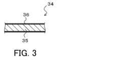
- FIG. 3 is a schematic configuration diagram of a fine water emitting element 34.
- FIG. 3 is a schematic diagram of a conductive polymer film 36.
- FIG. It is a flow chart which shows an example of fine water discharge processing. It is a flow chart which shows an example of moisture absorption control. It is a flowchart which shows an example of moisture release control.
- FIG. 3 is a schematic diagram of a conductive polymer film 36 in a moisture-absorbing state in a comparative example.
- FIG. 3 is a schematic diagram of a conductive polymer film 36 in a hygroscopic state in this embodiment.
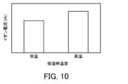
- 3 is an explanatory diagram showing an example of the relationship between temperature during moisture absorption and ionic current. It is a flow chart which shows fine water discharge processing of a modification. 13 is a flowchart showing a moisture absorption control according to a modified example. It is a schematic block diagram of the fine water discharge device 10B of a modification.
- FIG. 1 is a schematic diagram of the fine water discharge device 10.
- FIG. 2 is a schematic diagram of the fine water generation cartridge 30.
- FIG. 3 is a schematic diagram of the fine water emitting element 34.
- FIG. 4 is a schematic diagram of the conductive polymer film 36.
- the fine water discharge device 10 is configured as, for example, a beauty device or a medical device that discharges fine water toward the human body (skin, hair, etc.).
- the fine water discharge device 10 includes a duct 20, a fine water generation cartridge (fine water discharge cartridge) 30, a fan 40, and a control section 50.
- the fine water discharge device 10 is provided with various switches such as a start switch 55 for starting the operation of the fine water discharge device 10 and an air volume adjustment switch 56 for adjusting the air volume of the fan 40. Further, the fine water discharge device 10 includes an internal temperature sensor 57 that detects the temperature inside the fine water generation cartridge 30.
- the duct 20 is a cylindrical member such as a cylinder with both ends open, and has an inlet 21a at one end and an outlet 21b at the other end.
- a fan 40 and a fine water generation cartridge 30 are arranged in this order from the suction port 21a side.
- the fine water generating cartridge 30 includes a cylindrical case 32 with an outer diameter that can be placed inside the duct 20, and a fine water emitting element (fine water generating element) 34 provided inside the case 32. Equipped with.
- the fine water emitting element 34 includes a base material 35 and a conductive polymer film 36 formed on the surface of the base material 35.
- the base material 35 is made of a conductive material such as a metal material such as a stainless steel metal or a copper metal, a carbon material, or a conductive ceramic material.
- a stainless steel metal foil to which aluminum is added is used.
- the fine water emitting element 34 is formed in a corrugated plate shape, a honeycomb shape, a spiral shape, etc. so that air can flow through it and the surface area of the base material 35 (conductive polymer film 36) is as large as possible.
- An energization circuit 38 (see FIG. 1) that operates based on a control signal from the control section 50 is connected to the base material 35.
- the energization circuit 38 has a first energization state (weak energization state) in which a relatively small current is passed through the base material 35 and a second energization state (strong energization state) in which a relatively large large current is energized in the base material 35. , and a non-energized state in which power supply to the base material 35 is cut off.
- the conductive polymer film 36 is made of a conductive polymer compound such as a thiophene-based conductive polymer.
- a conductive polymer compound such as a thiophene-based conductive polymer.
- it is formed of PEDOT/PSS (poly(3,4-ethylenedioxythiophene)/poly(styrene sulfonic acid)) among thiophene-based conductive polymers.
- the conductive polymer film 36 can be made by dispersing PEDOT/PSS, which has a core-shell structure having a core of PEDOT and a shell of a sulfonic acid group, which is an acidic functional group capable of hydrogen bonding, in a solvent such as water. It is formed by applying it to the outer surface of the base material 35 and drying it. Therefore, as shown in FIG.
- PEDOT 36a exists in the core
- PSS 36b made of polymer material exists in the shell covering the core, and between each particle (between the shells)
- a nanochannel 36c which is a nanometer-sized flow path of about 2 nanometers (nm)
- the conductive polymer film 36 adsorbs water particles W as moisture.
- the fine water generation cartridge 30 changes to a hygroscopic state in which the conductive polymer membrane 36 adsorbs moisture in the air due to a temperature drop, and the adsorbed moisture becomes conductive due to a temperature rise.
- the state changes to a state where moisture is released from the polymer membrane 36.
- the thickness of the conductive polymer film 36 can be determined as appropriate depending on the required adsorption amount (release amount) of fine water. For example, when the conductive polymer film 36 is formed to have a thickness of 1 to 30 micrometers, sufficient water can be adsorbed to release fine water in a few seconds to several tens of seconds.
- the fine water generation cartridge 30 also generates uncharged fine water having a particle size of 50 nanometers or less, for example, about 1 to 2 nanometers, from the conductive polymer film 36 of the fine water discharge element 34. (uncharged fine water particles) are released.
- the reason for this particle size is that the size of the nanochannel 36c is 2 nanometers or less, so the increase in the temperature of the conductive polymer film 36 increases the mobility of the water in the nanochannel 36c, and the pressure This is thought to be due to a phenomenon in which moisture jumps out from the nanochannel 36c due to the rise. Further, even if the water particles aggregate after being ejected, the particle size is distributed within a range of 50 nanometers or less.
- the fan 40 is rotationally driven in a predetermined rotational direction so that air sucked into the duct 20 from the suction port 21a can be discharged from the discharge port 21b through the fine water generation cartridge 30.
- the fan 40 is rotationally driven by a motor (not shown), and is controlled by a control unit 50 through PWM (Pulse Width Modulation) control, voltage control, or the like.
- PWM Pulse Width Modulation
- the fan 40 may be a propeller fan, a sirocco fan, or the like.
- the control unit 50 is configured as a microprocessor centered on a CPU, and includes a ROM, a RAM, a timer, and an input/output port in addition to the CPU.
- the control unit 50 includes an internal temperature sensor that detects an operation signal from the start switch 55, an operation signal from the air volume adjustment switch 56, and the internal temperature of the fine water generation cartridge 30, such as the temperature of the fine water discharge element 34 (base material 35).
- a detection signal from 57 is inputted via the input port.
- the internal temperature sensor 57 can be, for example, a thermistor or a thermocouple.
- the control unit 50 outputs a drive signal to the motor that rotationally drives the fan 40, a drive signal to the switch of the energization circuit 38, etc. through the output port.
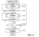
- FIG. 5 is a flowchart showing an example of fine water release processing.
- the control unit 50 executes moisture absorption control to cause the fine water generation cartridge 30 (fine water discharge element 34) to adsorb moisture (S100), and determines whether the first time has elapsed (S110). ).
- the first time is a time predetermined as an execution time of moisture absorption control, and is set to a time of several minutes, such as 5 minutes, for example. If the control unit 50 determines that the first time has not elapsed, the process returns to S100.
- the control unit 50 determines that the first time has elapsed, it executes moisture release control to release the adsorbed moisture as fine water from the fine water generation cartridge 30 (fine water release element 34) (S120), It is determined whether the second time has elapsed (S130).
- the second time is a time predetermined as the execution time of the moisture release control, and is set to a time of several minutes, such as two minutes, which is shorter than the first time, for example. Note that the second time may be the same time as the first time. If the control unit 50 determines that the second time has not elapsed, the process returns to S120.
- control unit 50 determines whether it is time to stop the fine water release process (S140), and when it determines that it is not the time to stop, it returns to S100 and executes moisture absorption control. In this way, the control unit 50 performs the moisture absorption control in S100 and the moisture release control in S120 while switching between them.
- the control unit 50 allows the user to perform a stop operation. If this is the case, it is determined in S140 that it is time to stop.
- control unit 50 determines that it is time to stop, it stops energizing the fine water generation cartridge 30 and the fan 40 (S150), and ends the fine water discharge process.
- the details of the moisture absorption control in S100 and the moisture release control in S120 will be described below.
- the moisture absorption control in S100 is executed based on the flowchart in FIG.
- the control unit 50 first rotates the fan 40 at high speed so as to blow air at a relatively high wind speed (S200), and the temperature of the fine water emitting element 34 (base material 35) detected by the internal temperature sensor 57 is the first. It is determined whether the temperature is below the temperature (S210).
- the first temperature is set to be higher than the environmental temperature, which is the temperature around the fine water discharge device 10.
- the first temperature is preset at, for example, 50° C., which is a temperature that normally does not fall below the environmental temperature.
- the control unit 50 determines that the temperature of the fine water emitting element 34 is equal to or lower than the first temperature, the control unit 50 sets the first energization state (weak energization state) in which a relatively small current (small current) is caused to flow to the base material 35.
- a control signal is output to the energizing circuit 38 to energize the fine water generation cartridge 30 with a small current (S220).
- the control unit 50 determines that the temperature of the fine water emitting element 34 is not lower than the first temperature, it skips S220. Note that when the moisture absorption control is executed immediately after the start of the fine water release process, the control unit 50 normally determines that the temperature is below the first temperature in S210 and energizes in S220. Therefore, the temperature of the fine water emitting element 34 increases.
- the control unit 50 determines whether the temperature of the fine water emitting element 34 detected by the internal temperature sensor 57 has reached the second temperature (S230).
- the second temperature is predetermined as a temperature several degrees Celsius higher than the first temperature, for example, 55 degrees Celsius.
- the control unit 50 determines that the temperature of the fine water emitting element 34 has not reached the second temperature, it ends the moisture absorption control.
- the control unit 50 determines that the temperature of the fine water discharge element 34 has reached the second temperature, it stops energizing the fine water generation cartridge 30 and blows air at a relatively slow wind speed (predetermined wind speed).
- the fan 40 is rotated at a low speed (S240), and the moisture absorption control is ended.
- the control section 50 stops energizing the fine water generation cartridge 30 and rotates the fan 40 at a low speed. Therefore, even if energization is started to the fine water generation cartridge 30 in S220, it is possible to suppress the temperature of the fine water emitting element 34 from rising above the second temperature.
- the moisture release control in S120 is executed based on the flowchart in FIG.
- the control unit 50 first rotates the fan 40 at a low speed so as to blow air at a relatively slow wind speed (predetermined wind speed) (S300).
- predetermined wind speed predetermined wind speed
- the control unit 50 only needs to rotate the fan 40 at a lower speed than in S200, and in this embodiment, the control unit 50 rotates the fan 40 at the same speed as in S240.
- the control unit 50 determines whether the temperature of the fine water emitting element 34 detected by the internal temperature sensor 57 is equal to or lower than the third temperature (S310).
- the third temperature is predetermined as a temperature higher than the above-mentioned second temperature, such as 65° C., for example.
- the control unit 50 determines that the temperature of the fine water emitting element 34 is equal to or lower than the third temperature
- the control unit 50 sets the second energization state (strong energization state) to flow a relatively large current (large current) to the base material 35.
- a control signal is output to the energization circuit 38 to energize the fine water generation cartridge 30 with a large current (S320). That is, in the moisture release control, the control unit 50 causes the fine water generation cartridge 30 to pass a current larger than that in the moisture absorption control, thereby raising the temperature of the fine water release element 34 higher than in the moisture absorption state. Further, if the control unit 50 determines that the temperature of the fine water emitting element 34 is not lower than the third temperature, it skips S320.
- the control unit 50 determines in S310 that the third temperature is lower than the third temperature, and in S320, a large current is applied to the fine water generation cartridge 30. energize.
- the control unit 50 determines whether the temperature of the fine water emitting element 34 detected by the internal temperature sensor 57 has reached the fourth temperature (S330).
- the fourth temperature is predetermined as a temperature higher than the third temperature by several degrees Celsius to ten degrees Celsius, for example, 75 degrees Celsius.
- the control unit 50 determines that the temperature of the fine water emitting element 34 has not reached the fourth temperature, it ends the moisture release control.
- the control unit 50 determines that the temperature of the fine water emitting element 34 has reached the fourth temperature, it stops energizing the fine water generating cartridge 30 (S340) and ends the moisture release control.
- the control unit 50 stops energizing the fine water generating cartridge 30. Thereby, it is possible to suppress the temperature of the fine water emitting element 34 from rising above the fourth temperature.
- the control unit 50 determines that the second time has elapsed in S130, and determines that it is not the stop timing in the subsequent S140, it switches to moisture absorption control in S100 (FIG. 5).
- the moisture absorption control since the control unit 50 rotates the fan 40 at high speed in S200, it is possible to quickly cool the fine water emitting element 34 whose temperature has risen to between the third temperature and the fourth temperature. Further, the control unit 50 rotates the fan 40 at high speed until the temperature of the fine water discharge element 34 decreases and reaches the second temperature, and when it is determined in S230 that the temperature of the fine water discharge element 34 has reached the second temperature. , the fan 40 is rotated at low speed in S240.
- the control unit 50 performs moisture absorption control between the first temperature and the second temperature (for example, 50°C to 55°C) and between the third temperature and the fourth temperature (for example, 65°C to 75°C). Execute while switching between moisture release control and moisture release control. Therefore, a temperature difference of approximately 10 to 20° C. occurs between the time of moisture absorption and the time of moisture release. If the temperature at the time of moisture absorption decreases by about 10 to 20 degrees Celsius from the temperature at the time of moisture release, the fine water release element 34 will appropriately change to the moisture absorption state and release fine water even if the temperature is higher than normal temperature, for example about 25 degrees Celsius. It becomes possible to absorb moisture.
- FIG. 8 is a schematic diagram of the conductive polymer film 36 in a hygroscopic state in a comparative example.
- FIG. 9 is a schematic diagram of the conductive polymer film 36 in a hygroscopic state in this embodiment.
- FIG. 10 is an explanatory diagram showing an example of the relationship between the temperature during hygroscopicity and the ion current.
- no current is passed through the fine water generating cartridge 30 (substrate 35) in the hygroscopic control, and the hygroscopic control is performed when the fine water emitting element 34 (substrate 35) is at room temperature, for example, about 25°C.
- the hygroscopic control is performed when the fine water emitting element 34 is at a relatively high temperature, such as 50 to 55°C.
- the left bar graph in FIG. 10 shows the comparative example, and shows the ion current detected when, for example, the hygroscopic control is performed at room temperature of about 25°C and the hygroscopic control is performed at about 45°C.
- the right bar graph in FIG. 10 shows the present embodiment, and shows the ion current detected when, for example, the hygroscopic control is performed at a high temperature of about 55°C and the hygroscopic control is performed at about 67°C.
- the amount of fine water discharged was determined by passing the fine water discharged from the fine water discharge element 34 through a neutralizer to charge it, measuring the electrical mobility of the charged fine water with a differential mobility analyzer, classifying it, and measuring the current (charge) of fine water of 50 nanometers or less. A larger ion current indicates a larger amount of fine water discharged under moisture release control.
- the water particles W of adjacent sulfonic acid groups combine to form bulk water, and the nanochannel 36c is filled with water. It is thought that the bound water particles W are less likely to exist in a cluster state with a particle size of about 2 nanometers or less, and are less likely to be released as fine water in a moisture-releasing state. As a result, the amount of released fine water of 50 nanometers or less is reduced (see FIG. 10).
- the fine water release element 34 is brought to a high temperature state by moisture absorption control, so the shell (PSS 36b) contracts and at the same time, the nanochannel 36c becomes smaller.
- the shell (PSS 36b) contracts and at the same time, the nanochannel 36c becomes smaller.
- the number of sites that can adsorb water within the nanochannel 36c decreases, and the total amount of water that can be adsorbed decreases.
- the number of water particles W existing in a cluster state with a particle size of about 2 nanometers or less increases.
- the amount of fine water of 50 nanometers or less released is greater than that of the comparative example (see FIG.
- the PSS 36b of the shell further contracts.
- the release of fine water from within the nanochannels 36c is promoted by the temperature rise, contraction of the shell (PSS 36b), and the above-mentioned difference in water concentration between the surface and the inside of the element.
- the fine water discharge device 10 discharges fine water toward the skin, hair, etc. of the human body.
- the stratum corneum on the surface of the skin has minute gaps of about 20 to 50 nanometers or less. Therefore, if the particle size of the fine water is 50 nanometers or less, it is easy for the fine water to penetrate from the stratum corneum into the inside of the skin.
- the particle size of the fine water is 50 nanometers or less, it is easy for the fine water to penetrate into the inside of the hair.
- the fine water discharge device 10 of this embodiment makes it easier for water particles W to exist in a state of 50 nanometers or less when absorbing moisture, thereby promoting the discharge of fine water of 50 nanometers or less when releasing moisture, and improving the effect of penetrating the fine water into the skin and hair. This allows the fine water to fully penetrate the skin and hair, resulting in an improved moisturizing effect.
- the fine water discharge device 10 of the present embodiment described above performs moisture absorption control in which a small current is applied so that the fine water discharge element 34 enters the moisture absorption state, and the temperature of the fine water discharge element 34 is made higher than the temperature in the moisture absorption state.
- the moisture release control is performed by applying a large current to bring the moisture into the moisture release state.
- the amount of water adsorbed to the conductive polymer film 36 is controlled, the binding of water particles W is suppressed, and the total amount of water is It is possible to increase the adsorption ratio of water particles W that become fine water. Therefore, appropriate release of fine water can be promoted.
- control unit 50 starts applying a small current when the temperature of the fine water releasing element 34 is below the first temperature, and stops applying the current when the temperature is above the second temperature, so that the fine water is released. It is possible to prevent the temperature of the element 34 from becoming too high and being unable to absorb moisture.
- control unit 50 starts applying a large current when the temperature of the fine water emitting element 34 is below the third temperature, and stops applying the large current when the temperature is above the fourth temperature. It is possible to suppress excessive temperature rise while ensuring a temperature difference between the two and performing appropriate moisture absorption and desorption.
- control unit 50 rotates the fan 40 at low speed during moisture release control and rotates the fan 40 at high speed when starting moisture absorption control, the fine water release element 34 is cooled during moisture absorption control after moisture release control. can be quickly brought into a moisture-absorbing state.
- the PSS 36b of the shell contracts and suppresses the amount of water adsorbed in the nanochannels 36c, so that the total amount of water adsorbed is lower than that when adsorbed at room temperature. Although this decreases, the proportion of water particles W that becomes fine water increases.
- the PSS 36b of the shell further contracts, and fine water is released from within the nanochannel 36c due to the difference in water concentration between the element surface and the inside.
- the fine water discharge device 10 can absorb and release moisture by making the fine water discharge element 34 having the conductive polymer film 36 having a core-shell structure function more appropriately.
- the fan 40 is rotated at high speed in step S200 of the moisture absorption control, but it is usually not necessary to operate the fan 40 at high speed for cooling in the moisture absorption control immediately after the start of the fine water release process (first time). S200 may be omitted.
- the method is not limited to rotating the fan 40 at high speed under moisture absorption control, and the following method may be used.
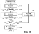
- FIG. 11 is a flowchart showing a modified example of fine water release processing.
- FIG. 12 is a flowchart showing moisture absorption control in a modified example. In the following modified examples, the same step numbers are given to the same processes as in the embodiment, and the description thereof will be omitted.
- the control unit 50 determines that it is not the stop timing in S140, it performs cooling control to rotate the fan 40 at high speed for a predetermined period of time (S145), and then performs cooling control in S100. Shift to moisture absorption control. That is, the fine water release process of the embodiment ( Figure 5) is different.
- the predetermined time in the cooling control in S145 is predetermined as the time required to bring the fine water discharge element 34, which has become relatively high temperature due to the moisture absorption control, to the temperature of the moisture absorption state.
- control unit 50 operates the fan 40 at high speed until it detects that the temperature of the fine water discharge element 34 has reached a temperature at which moisture is absorbed (for example, a second temperature or lower). After the rotation, the process may proceed to moisture absorption control in S100.
- the control unit 50 first rotates the fan 40 at a low speed so as to blow air at a relatively slow wind speed (predetermined wind speed) (S200B). Further, if the control unit 50 determines in S230 that the temperature of the fine water emitting element 34 has reached the second temperature, it stops the power supply to the fine water generating cartridge 30 (S240B), and ends the moisture absorption control. In this way, in the moisture absorption control of the modified example, the fan 40 is rotated at low speed when moisture absorption control is started, and the fan 40 is kept rotating at low speed without being stopped when moisture absorption control is ended.
- predetermined wind speed predetermined wind speed
- the fine water releasing element 34 can adsorb moisture in a period of about several seconds to several tens of seconds. Therefore, if the temperature of the fine water release element 34 reaches the second temperature during the first time (S110) during which the moisture absorption control is performed and moisture is adsorbed by the fine water release element 34, the moisture absorption control is performed. There is no need to provide cooling control (S145) between this and moisture release control.
- predetermined temperatures are used as the first to fourth temperatures, but the present invention is not limited to this, and temperatures set based on the environmental temperature, which is the temperature around the fine water discharge device 10 and the fine water generating cartridge 30, may be used.
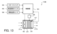
- FIG. 13 is a schematic diagram of a modified fine water discharge device 10B. This fine water discharge device 10B is equipped with an environmental temperature sensor 58 that detects the environmental temperature, which is the temperature around the fine water discharge device 10. The control unit 50 may set the first to fourth temperatures based on the environmental temperature detected by the environmental temperature sensor 58.
- control unit 50 may set the first temperature by adding a temperature of several tens of degrees Celsius, such as 20°C to 30°C (first predetermined temperature) to the environmental temperature detected by the environmental temperature sensor 58, and set the second temperature by adding a temperature of several degrees Celsius to tens of degrees Celsius (second predetermined temperature) to the first temperature.
- the control unit 50 may also set the third temperature by adding a temperature of several tens of degrees Celsius to tens of degrees Celsius (third predetermined temperature) to the second temperature, and set the fourth temperature by adding a temperature of several degrees Celsius to tens of degrees Celsius (fourth predetermined temperature) to the third temperature.
- control unit 50 may selectively set the first to fourth temperatures based on the environmental temperature detected by the environmental temperature sensor 58. For example, the control unit 50 sets temperatures 1A, 2A, 3A, and 4A as the first temperature, second temperature, third temperature, and fourth temperature, respectively when the environmental temperature is low, and when the environmental temperature is high. In this case, temperature 1B, temperature 2B, temperature 3B, and temperature 4B are set respectively. Each temperature is defined as temperature 1A, temperature 1B, temperature 2A, temperature 2B, temperature 3A, temperature 3B, temperature 4A, temperature 4B from the lowest one, and is determined in advance and stored in a storage unit such as a ROM of the control unit 50. Bye. Further, the control unit 50 may change the settings of the first to fourth temperatures in accordance with changes in the environmental temperature during execution of the fine water release process.
- the fan 40 changes the wind speed in two stages, but the fan 40 is not limited to this, and the wind speed may be changed in three or more stages.
- control unit 50 terminates the passage of current when the second temperature is reached in moisture absorption control (when the temperature is equal to or higher than the second temperature), but this is not limited to the above and the amount of current flow may be reduced to suppress temperature rise. Also, the control unit 50 terminates the passage of current when the fourth temperature is reached in moisture release control (when the temperature is equal to or higher than the fourth temperature), but this is not limited to the above and the amount of current flow may be reduced to suppress temperature rise.
- the temperature of the fine water emitting element 34 is increased by energizing the base material 35, that is, an example in which electrical energy is supplied as energy. may be supplied, or both electrical energy and thermal energy may be supplied.
- the first energy is supplied to the fine water release element 34
- the second energy that makes the temperature higher than that in the moisture absorption control is supplied to the fine water release element 34.
- the type of energy supplied may be different from that for moisture release control.
- the first energy may be supplied from one supply section to the fine water discharge element 34, and in the moisture release control, the second energy may be supplied to the fine water discharge element 34 from two or more supply sections.
- the fine water discharge device 10 of the embodiment corresponds to the "fine water discharge device" of the present disclosure
- the fine water discharge element 34 corresponds to the "fine water discharge element”
- the control unit 50 corresponds to the "control unit”.
- Internal temperature sensor 57 corresponds to a "temperature sensor”.
- the fan 40 corresponds to the "air blower”.
- an example of the fine water discharge method of this indication is also made clear by demonstrating the operation
- the fine water emitting device (10) of the present disclosure includes a base material (35) and a conductive polymer film (36) provided on the base material (35), and a moisture absorption state in which water is adsorbed on the conductive polymer film (36), and a moisture release state in which the water adsorbed on the conductive polymer film (36) is released as fine water with a particle size of 50 nanometers or less.
- a changing microscopic water emitting element (34) for supplying energy to the microscopic water emitting element (34); and supplying first energy to bring the microscopic water emitting element (34) into the moisture absorbing state.
- the present invention is summarized as follows: a moisture release control that controls the supply section (38) to supply the second energy; and a control section (50) that executes the moisture release control.
- the fine water emitting device of the present disclosure includes moisture absorption control that supplies first energy that brings the fine water emitting element into a moisture absorbing state, and second energy that makes the fine water emitting element higher in temperature than the moisture absorbing state and brings the fine water releasing element into a moisture releasing state.
- the temperature of the fine water release element is made higher than in moisture absorption control which does not supply energy, so it is possible to control the amount of moisture adsorbed on the conductive polymer film. Therefore, it is possible to suppress the binding of water particles and increase the adsorption ratio of water particles that become fine water to the total amount of water adsorbed, so that release of fine water during moisture release control can be promoted.
- the control unit (50) also includes a temperature sensor (57) that detects the temperature of the fine water emitting element (34), and the control unit (50) is configured such that in the moisture absorption control, the temperature of the fine water emitting element (34) is set to a first temperature.
- the supply of the first energy is started in the following cases, and the supply of the first energy is stopped when the temperature of the fine water emitting element (34) is a second temperature higher than the first temperature.
- the supply unit (38) may also be controlled. This makes it possible to maintain the temperature of the fine water emitting element within an appropriate range during moisture absorption control, and to appropriately suppress the bonding of water particles inside the fine water emitting element.
- the control unit (50) starts supplying the second energy when the temperature of the fine water release element (34) is a third temperature higher than the second temperature or less
- the supply unit (38) may be controlled so as to stop supplying the second energy when the temperature of the fine water emitting element (34) is equal to or higher than a fourth temperature higher than the third temperature.
- the air blowing unit (40) is configured to blow air through the fine water emitting element (34) so that air circulates therethrough, and the control unit (50) controls the air blowing unit to blow air at a predetermined wind speed in the moisture release control. (40) to blow air at a faster wind speed than the predetermined wind speed when switching from the moisture release control to the moisture absorption control or before switching to the moisture absorption control. It can also be used as a thing. In this way, cooling of the fine water emitting element can be promoted, so that the fine water emitting element can be quickly changed to a moisture absorbing state after moisture release control.
- an environmental temperature sensor (58) that detects the environmental temperature may be provided, and the control section (50) may adjust the first energy according to the environmental temperature.
- the control unit (50) also includes an environmental temperature sensor (58) that detects an environmental temperature, and the control unit (50) sets the first temperature to a temperature obtained by adding a first predetermined temperature to the environmental temperature, and The second temperature may be set to a temperature obtained by adding a second predetermined temperature to the temperature.
- control unit (50) sets the third temperature to a temperature obtained by adding a third predetermined temperature to the second temperature, and sets the third temperature to a temperature obtained by adding a fourth predetermined temperature to the third temperature. It is also possible to set four temperatures.
- the correspondence relationship between the main elements of the embodiment and the main elements of the present disclosure described in the column of means for solving the problem is the same as the correspondence relationship between the main elements of the embodiment and the main elements of the present disclosure described in the column of means for solving the problem. Since this is an example for specifically explaining a mode for implementing the above, it is not intended to limit the elements of the present disclosure described in the column of means for solving the problems. In other words, the interpretation of the present disclosure described in the column of means to solve the problem should be made based on the description in that column, and the embodiments should be interpreted based on the book described in the column of means to solve the problem. This is just one specific example of disclosure.
- the present disclosure can be used in the technical field of emitting fine water from a fine water emitting element.
- Fine water release device 10B Fine water release device, 20 Duct, 21a Inlet, 21b Outlet, 30 Fine water generation cartridge, 32 Case, 34 Fine water release element (fine water generation element), 35 Base material, 36 Conductive polymer membrane , 36a PEDOT, 36b PSS, 36c nanochannel, 38 energizing circuit (supply section), 40 fan (blower section), 50 control section, 55 start switch, 56 air volume adjustment switch, 57 internal temperature sensor, 58 environmental temperature sensor, W water particles.
- Base material 36 Conductive polymer membrane , 36a PEDOT, 36b PSS, 36c nanochannel, 38 energizing circuit (supply section), 40 fan (blower section), 50 control section, 55 start switch, 56 air volume adjustment switch, 57 internal temperature sensor, 58 environmental temperature sensor, W water particles.
Landscapes
- Chemical & Material Sciences (AREA)
- Analytical Chemistry (AREA)
- Chemical Kinetics & Catalysis (AREA)
- Organic Chemistry (AREA)
- Oil, Petroleum & Natural Gas (AREA)
- Engineering & Computer Science (AREA)
- General Health & Medical Sciences (AREA)
- Health & Medical Sciences (AREA)
- General Chemical & Material Sciences (AREA)
- Electromagnetism (AREA)
- Toxicology (AREA)
- Physics & Mathematics (AREA)
- Dermatology (AREA)
- Drying Of Gases (AREA)
Abstract
Description
基材と、前記基材に設けられた導電性高分子膜とを有し、空気中の水分を前記導電性高分子膜に吸着する吸湿状態と前記導電性高分子膜に吸着した水分を粒径が50ナノメートル以下の微細水として放出する放湿状態とに変化する微細水放出素子と、
前記微細水放出素子にエネルギを供給する供給部と、
前記微細水放出素子を前記吸湿状態とする第1エネルギを供給するように前記供給部を制御する吸湿制御と、前記微細水放出素子の温度を前記吸湿状態の温度より高くして前記微細水放出素子を前記放湿状態とする第2エネルギを供給するように前記供給部を制御する放湿制御と、を実行する制御部と、
を備えることを要旨とする。
基材と、前記基材に設けられた導電性高分子膜とを有し、空気中の水分を前記導電性高分子膜に吸着する吸湿状態と前記導電性高分子膜に吸着した水分を粒径が50ナノメートル以下の微細水として放出する放湿状態とに変化する微細水放出素子から微細水を放出させる微細水放出方法であって、
前記微細水放出素子を前記吸湿状態とする第1エネルギを供給するように供給部を制御する吸湿制御ステップと、
前記微細水放出素子の温度を前記吸湿状態の温度より高くして前記微細水放出素子を前記放湿状態とする第2エネルギを供給するように前記供給部を制御する放湿制御ステップと、
を含むことを要旨とする。
Claims (14)
- 基材と、前記基材に設けられた導電性高分子膜とを有し、空気中の水分を前記導電性高分子膜に吸着する吸湿状態と前記導電性高分子膜に吸着した水分を粒径が50ナノメートル以下の微細水として放出する放湿状態とに変化する微細水放出素子と、
前記微細水放出素子にエネルギを供給する供給部と、
前記微細水放出素子を前記吸湿状態とする第1エネルギを供給するように前記供給部を制御する吸湿制御と、前記微細水放出素子の温度を前記吸湿状態の温度より高くして前記微細水放出素子を前記放湿状態とする第2エネルギを供給するように前記供給部を制御する放湿制御と、を実行する制御部と、
を備える微細水放出装置。 - 前記微細水放出素子の温度を検出する温度センサを備え、
前記制御部は、前記吸湿制御では、前記微細水放出素子の温度が第1温度以下の場合に前記第1エネルギの供給を開始し、前記微細水放出素子の温度が前記第1温度より高い第2温度以上の場合に前記第1エネルギの供給を停止するように前記供給部を制御する、
請求項1に記載の微細水放出装置。 - 前記制御部は、前記放湿制御では、前記微細水放出素子の温度が前記第2温度より高い第3温度以下の場合に前記第2エネルギの供給を開始し、前記微細水放出素子の温度が前記第3温度より高い第4温度以上の場合に前記第2エネルギの供給を停止するように前記供給部を制御する、
請求項2に記載の微細水放出装置。 - 前記微細水放出素子を空気が流通するように送風する送風部を備え、
前記制御部は、前記放湿制御では所定の風速で送風するように前記送風部を制御し、前記放湿制御から前記吸湿制御に切り替えた場合または前記吸湿制御に切り替える前に前記所定の風速よりも速い風速で送風するように前記送風部を制御する、
請求項1または2に記載の微細水放出装置。 - 環境温度を検出する環境温度センサを備え、
前記制御部は、前記環境温度に応じて前記第1エネルギを調節する、
請求項1に記載の微細水放出装置。 - 環境温度を検出する環境温度センサを備え、
前記制御部は、前記環境温度に第1の所定温度を加えた温度に前記第1温度を設定し、前記第1温度に第2の所定温度を加えた温度に前記第2温度を設定する、
請求項2に記載の微細水放出装置。 - 前記制御部は、前記第2温度に第3の所定温度を加えた温度に前記第3温度を設定し、前記第3温度に第4の所定温度を加えた温度に前記第4温度を設定する、
請求項3に記載の微細水放出装置。 - 基材と、前記基材に設けられた導電性高分子膜とを有し、空気中の水分を前記導電性高分子膜に吸着する吸湿状態と前記導電性高分子膜に吸着した水分を粒径が50ナノメートル以下の微細水として放出する放湿状態とに変化する微細水放出素子から微細水を放出させる微細水放出方法であって、
前記微細水放出素子を前記吸湿状態とする第1エネルギを供給するように供給部を制御する吸湿制御ステップと、
前記微細水放出素子の温度を前記吸湿状態の温度より高くして前記微細水放出素子を前記放湿状態とする第2エネルギを供給するように前記供給部を制御する放湿制御ステップと、
を含む微細水放出方法。 - 前記吸湿制御ステップでは、温度センサにより検出される前記微細水放出素子の温度が第1温度以下の場合に前記第1エネルギの供給を開始し、前記微細水放出素子の温度が前記第1温度より高い第2温度以上の場合に前記第1エネルギの供給を停止するように前記供給部を制御する、
請求項8に記載の微細水放出方法。 - 前記放湿制御ステップでは、前記微細水放出素子の温度が前記第2温度より高い第3温度以下の場合に前記第2エネルギの供給を開始し、前記微細水放出素子の温度が前記第3温度より高い第4温度以上の場合に前記第2エネルギの供給を停止するように前記供給部を制御する、
請求項9に記載の微細水放出方法。 - 前記放湿制御ステップでは、前記微細水放出素子を空気が流通するように送風する送風部が所定の風速で送風するように前記送風部を制御し、
前記放湿制御ステップから前記吸湿制御ステップに切り替えた場合または前記吸湿制御ステップに切り替える前に前記所定の風速よりも速い風速で送風するように前記送風部を制御する、
請求項8または9に記載の微細水放出方法。 - 前記吸湿制御ステップでは、環境温度センサにより検出される環境温度に応じて前記第1エネルギを調節する、
請求項8に記載の微細水放出方法。 - 前記吸湿制御ステップでは、環境温度センサにより検出される環境温度に第1の所定温度を加えた温度に前記第1温度を設定し、前記第1温度に第2の所定温度を加えた温度に前記第2温度を設定する、
請求項9に記載の微細水放出方法。 - 前記放湿制御ステップでは、前記第2温度に第3の所定温度を加えた温度に前記第3温度を設定し、前記第3温度に第4の所定温度を加えた温度に前記第4温度を設定する、
請求項10に記載の微細水放出方法。
Priority Applications (3)
| Application Number | Priority Date | Filing Date | Title |
|---|---|---|---|
| JP2024548122A JPWO2024062784A1 (ja) | 2022-09-21 | 2023-08-03 | |
| EP23867910.4A EP4591993A4 (en) | 2022-09-21 | 2023-08-03 | FINE WATER RELEASE DEVICE AND FINE WATER RELEASE METHOD |
| CN202380066630.6A CN119894610A (zh) | 2022-09-21 | 2023-08-03 | 微细水放出装置以及微细水放出方法 |
Applications Claiming Priority (2)
| Application Number | Priority Date | Filing Date | Title |
|---|---|---|---|
| JP2022-150630 | 2022-09-21 | ||
| JP2022150630 | 2022-09-21 |
Publications (1)
| Publication Number | Publication Date |
|---|---|
| WO2024062784A1 true WO2024062784A1 (ja) | 2024-03-28 |
Family
ID=90454092
Family Applications (1)
| Application Number | Title | Priority Date | Filing Date |
|---|---|---|---|
| PCT/JP2023/028488 Ceased WO2024062784A1 (ja) | 2022-09-21 | 2023-08-03 | 微細水放出装置および微細水放出方法 |
Country Status (4)
| Country | Link |
|---|---|
| EP (1) | EP4591993A4 (ja) |
| JP (1) | JPWO2024062784A1 (ja) |
| CN (1) | CN119894610A (ja) |
| WO (1) | WO2024062784A1 (ja) |
Families Citing this family (1)
| Publication number | Priority date | Publication date | Assignee | Title |
|---|---|---|---|---|
| JP7452384B2 (ja) * | 2020-11-06 | 2024-03-19 | 株式会社アイシン | 培養装置および培養方法 |
Citations (4)
| Publication number | Priority date | Publication date | Assignee | Title |
|---|---|---|---|---|
| JP2019018195A (ja) | 2017-07-19 | 2019-02-07 | アイシン精機株式会社 | 微細水粒子放出素子、微細水粒子放出装置及び微細水粒子放出素子の製造方法 |
| WO2020054100A1 (ja) | 2018-09-14 | 2020-03-19 | アイシン精機株式会社 | 微細水放出装置 |
| JP2021019995A (ja) * | 2019-07-30 | 2021-02-18 | アイシン精機株式会社 | 人体用微細水放出装置 |
| WO2022097447A1 (ja) * | 2020-11-06 | 2022-05-12 | 株式会社アイシン | 培養装置および培養方法 |
Family Cites Families (6)
| Publication number | Priority date | Publication date | Assignee | Title |
|---|---|---|---|---|
| JP4337550B2 (ja) * | 2004-01-05 | 2009-09-30 | パナソニック株式会社 | 除湿装置 |
| JP2008038708A (ja) * | 2006-08-03 | 2008-02-21 | Toyota Motor Corp | キャニスタ |
| JP6384432B2 (ja) * | 2015-09-02 | 2018-09-05 | 株式会社豊田中央研究所 | ガス貯蔵装置 |
| JP7392496B2 (ja) * | 2020-01-28 | 2023-12-06 | 株式会社アイシン | 微細水放出装置 |
| CN112156614B (zh) * | 2020-09-09 | 2021-10-15 | 埃尔利德(广东)智能科技有限公司 | 基于压力露点的模块式吸干机控制系统及控制方法 |
| JP7679634B2 (ja) * | 2021-02-12 | 2025-05-20 | 株式会社アイシン | 微細水粒子放出装置および微細水粒子放出方法 |
-
2023
- 2023-08-03 WO PCT/JP2023/028488 patent/WO2024062784A1/ja not_active Ceased
- 2023-08-03 JP JP2024548122A patent/JPWO2024062784A1/ja active Pending
- 2023-08-03 EP EP23867910.4A patent/EP4591993A4/en active Pending
- 2023-08-03 CN CN202380066630.6A patent/CN119894610A/zh active Pending
Patent Citations (4)
| Publication number | Priority date | Publication date | Assignee | Title |
|---|---|---|---|---|
| JP2019018195A (ja) | 2017-07-19 | 2019-02-07 | アイシン精機株式会社 | 微細水粒子放出素子、微細水粒子放出装置及び微細水粒子放出素子の製造方法 |
| WO2020054100A1 (ja) | 2018-09-14 | 2020-03-19 | アイシン精機株式会社 | 微細水放出装置 |
| JP2021019995A (ja) * | 2019-07-30 | 2021-02-18 | アイシン精機株式会社 | 人体用微細水放出装置 |
| WO2022097447A1 (ja) * | 2020-11-06 | 2022-05-12 | 株式会社アイシン | 培養装置および培養方法 |
Non-Patent Citations (1)
| Title |
|---|
| See also references of EP4591993A4 |
Also Published As
| Publication number | Publication date |
|---|---|
| EP4591993A1 (en) | 2025-07-30 |
| EP4591993A4 (en) | 2026-01-21 |
| JPWO2024062784A1 (ja) | 2024-03-28 |
| CN119894610A (zh) | 2025-04-25 |
Similar Documents
| Publication | Publication Date | Title |
|---|---|---|
| JP6528097B2 (ja) | 除湿装置及び除湿方法 | |
| JP7091692B2 (ja) | 微細水粒子放出素子、微細水粒子放出装置及び微細水粒子放出素子の製造方法 | |
| US12415195B2 (en) | Fine water discharging element, fine water discharge device and method for manufacturing fine water discharging element | |
| JP2020116032A (ja) | 加熱送風装置 | |
| WO2024062784A1 (ja) | 微細水放出装置および微細水放出方法 | |
| WO2003077710A1 (en) | Air conditioning seat device | |
| CN105473208A (zh) | 除湿机 | |
| JP6413680B2 (ja) | 加湿装置 | |
| JP7452384B2 (ja) | 培養装置および培養方法 | |
| JP5587571B2 (ja) | 乾式減湿装置の運転方法 | |
| JP7392496B2 (ja) | 微細水放出装置 | |
| JP4438959B2 (ja) | 除湿装置及び除湿方法 | |
| JP2001174009A (ja) | 湿度調節装置 | |
| EP4201505A1 (en) | Water collecting apparatus and water collecting method | |
| JP6668739B2 (ja) | 除加湿装置 | |
| JP2008249272A (ja) | 冷房空調システム | |
| JP7286977B2 (ja) | 送風装置 | |
| JP4781886B2 (ja) | 空調装置 | |
| JP2006071171A (ja) | 調湿装置 | |
| JP4674442B2 (ja) | 空調座席装置 | |
| JP2005058937A (ja) | 吸着式除湿機 | |
| JP2002317967A (ja) | 調湿機 | |
| JP2014035135A (ja) | 調湿装置 | |
| JP2013160459A (ja) | 調湿装置 | |
| JP2015033937A (ja) | デシカント式車両空調装置 |
Legal Events
| Date | Code | Title | Description |
|---|---|---|---|
| 121 | Ep: the epo has been informed by wipo that ep was designated in this application |
Ref document number: 23867910 Country of ref document: EP Kind code of ref document: A1 |
|
| WWE | Wipo information: entry into national phase |
Ref document number: 2024548122 Country of ref document: JP |
|
| WWE | Wipo information: entry into national phase |
Ref document number: 202380066630.6 Country of ref document: CN |
|
| WWE | Wipo information: entry into national phase |
Ref document number: 2023867910 Country of ref document: EP |
|
| NENP | Non-entry into the national phase |
Ref country code: DE |
|
| WWP | Wipo information: published in national office |
Ref document number: 202380066630.6 Country of ref document: CN |
|
| ENP | Entry into the national phase |
Ref document number: 2023867910 Country of ref document: EP Effective date: 20250422 |
|
| WWP | Wipo information: published in national office |
Ref document number: 2023867910 Country of ref document: EP |