WO2024070061A1 - プレス成形品の製造方法 - Google Patents
プレス成形品の製造方法 Download PDFInfo
- Publication number
- WO2024070061A1 WO2024070061A1 PCT/JP2023/020982 JP2023020982W WO2024070061A1 WO 2024070061 A1 WO2024070061 A1 WO 2024070061A1 JP 2023020982 W JP2023020982 W JP 2023020982W WO 2024070061 A1 WO2024070061 A1 WO 2024070061A1
- Authority
- WO
- WIPO (PCT)
- Prior art keywords
- press
- die
- formed product
- springback
- projection angle
- Prior art date
- Legal status (The legal status is an assumption and is not a legal conclusion. Google has not performed a legal analysis and makes no representation as to the accuracy of the status listed.)
- Ceased
Links
Images

Classifications
-
- B—PERFORMING OPERATIONS; TRANSPORTING
- B21—MECHANICAL METAL-WORKING WITHOUT ESSENTIALLY REMOVING MATERIAL; PUNCHING METAL
- B21D—WORKING OR PROCESSING OF SHEET METAL OR METAL TUBES, RODS OR PROFILES WITHOUT ESSENTIALLY REMOVING MATERIAL; PUNCHING METAL
- B21D22/00—Shaping without cutting, by stamping, spinning, or deep-drawing
- B21D22/20—Deep-drawing
- B21D22/26—Deep-drawing for making peculiarly, e.g. irregularly, shaped articles
-
- B—PERFORMING OPERATIONS; TRANSPORTING
- B21—MECHANICAL METAL-WORKING WITHOUT ESSENTIALLY REMOVING MATERIAL; PUNCHING METAL
- B21D—WORKING OR PROCESSING OF SHEET METAL OR METAL TUBES, RODS OR PROFILES WITHOUT ESSENTIALLY REMOVING MATERIAL; PUNCHING METAL
- B21D22/00—Shaping without cutting, by stamping, spinning, or deep-drawing
- B21D22/20—Deep-drawing
- B21D22/21—Deep-drawing without fixing the border of the blank
-
- B—PERFORMING OPERATIONS; TRANSPORTING
- B21—MECHANICAL METAL-WORKING WITHOUT ESSENTIALLY REMOVING MATERIAL; PUNCHING METAL
- B21D—WORKING OR PROCESSING OF SHEET METAL OR METAL TUBES, RODS OR PROFILES WITHOUT ESSENTIALLY REMOVING MATERIAL; PUNCHING METAL
- B21D22/00—Shaping without cutting, by stamping, spinning, or deep-drawing
- B21D22/20—Deep-drawing
- B21D22/30—Deep-drawing to finish articles formed by deep-drawing
-
- B—PERFORMING OPERATIONS; TRANSPORTING
- B21—MECHANICAL METAL-WORKING WITHOUT ESSENTIALLY REMOVING MATERIAL; PUNCHING METAL
- B21D—WORKING OR PROCESSING OF SHEET METAL OR METAL TUBES, RODS OR PROFILES WITHOUT ESSENTIALLY REMOVING MATERIAL; PUNCHING METAL
- B21D24/00—Special deep-drawing arrangements in, or in connection with, presses
- B21D24/005—Multi-stage presses
-
- B—PERFORMING OPERATIONS; TRANSPORTING
- B21—MECHANICAL METAL-WORKING WITHOUT ESSENTIALLY REMOVING MATERIAL; PUNCHING METAL
- B21D—WORKING OR PROCESSING OF SHEET METAL OR METAL TUBES, RODS OR PROFILES WITHOUT ESSENTIALLY REMOVING MATERIAL; PUNCHING METAL
- B21D53/00—Making other particular articles
- B21D53/88—Making other particular articles other parts for vehicles, e.g. cowlings, mudguards
-
- B—PERFORMING OPERATIONS; TRANSPORTING
- B21—MECHANICAL METAL-WORKING WITHOUT ESSENTIALLY REMOVING MATERIAL; PUNCHING METAL
- B21D—WORKING OR PROCESSING OF SHEET METAL OR METAL TUBES, RODS OR PROFILES WITHOUT ESSENTIALLY REMOVING MATERIAL; PUNCHING METAL
- B21D11/00—Bending not restricted to forms of material mentioned in only one of groups B21D5/00, B21D7/00, B21D9/00; Bending not provided for in groups B21D5/00 - B21D9/00; Twisting
- B21D11/14—Twisting
Definitions
- the present invention relates to a method for manufacturing a press-molded product that is curved when viewed from above and has at least a top plate portion and a vertical wall portion that continues from the top plate portion.
- Automobile parts including parts of their structure, include press-formed products 1, which are curved when viewed from above and have at least a top plate portion 3 and a vertical wall portion 5 continuing from the top plate portion 3, as shown in Figure 3.
- press-formed products if the die is moved to the bottom dead center and then released from the die, springback occurs, making the press-formed product prone to twisting.
- the stress generated at the bottom dead center of forming increases due to the increased strength, and after release from the die, the large stress is released, making it prone to large twisting, which is problematic.
- Patent Document 1 discloses a method of reducing the stress generated by providing through holes or grooves in a press-formed product.
- paragraph [0004] of Patent Document 2 discloses a method of press-forming using a die that provides a twist angle in the opposite direction to springback.
- Patent Document 1 creates through holes and grooves in the press molded product, resulting in a press molded product with a shape different from the target, which can lead to problems such as reduced rigidity when assembled to the vehicle body and difficulty in joining parts together.
- the press molding method described in Patent Document 2 involves applying a twist angle to the die in only one direction, the opposite direction to springback, for press molding, which poses the problem that it is difficult to set the twist angle to be applied to the die.
- the twist angle is too small, the twist that is springback cannot be fully eliminated, and if the twist angle is too large, twist in the opposite direction remains, so it is necessary to apply an appropriate twist angle, which is difficult.
- the present invention has been made in consideration of the above problems, and its purpose is to provide a method for manufacturing a press-molded product that is curved when viewed from above and has at least a top plate portion and a vertical wall portion continuing from the top plate portion, and that can reduce shape errors caused by springback after demolding.
- the manufacturing method of a press-molded product according to the present invention is a manufacturing method of a press-molded product that is curved when viewed from above, has at least a top plate portion and a vertical wall portion continuing from the top plate portion, and is manufactured by imparting a projection angle to a die in order to reduce an error from a target shape due to springback after demolding, and is characterized by comprising: a molding process of press-molding using a molding die imparted with a first projection angle such that a twist due to springback in the opposite direction (reverse twist) remains compared to the twist (positive twist) that occurs due to springback when press-molding is performed in one process without imparting a projection angle to the die; and a restriking process of press-molding the molded product molded in the molding process using a restriking die imparted with a second projection angle.
- the manufacturing method of the press-formed product according to the present invention is characterized in that, in the invention (1) above, the first projection angle is greater than the one-step projection angle at which the twist due to springback when the press-formed product is press-formed in one step is equal to or smaller than a predetermined threshold value.
- the manufacturing method of the press-formed product according to the present invention is the same as the invention (2) above, and is characterized in that a press forming analysis and a springback analysis of the press-formed product are performed in advance to determine the direction of twist due to springback and the one-step projection angle.
- the manufacturing method of the press-formed product according to the present invention is the same as the invention (2) above, and is characterized in that the actual press-formation of the press-formed product is performed in advance to determine the direction of twist due to springback and the one-step projection angle.
- the manufacturing method of the press-molded product according to the present invention is characterized in that, in any of the inventions (1) to (4) above, the first projection angle or the second projection angle is set as an inclination angle of the top plate molding surface portion of the widthwise cross section at the longitudinal end of the molding die or the restriking die, based on the top plate molding surface portion of the widthwise cross section at the longitudinal center of the molding die or the restriking die.
- the manufacturing method of the press-molded product according to the present invention is characterized in that, in any of the inventions (1) to (5) above, the absolute value of the second projection angle in the restriking process is smaller than the absolute value of the first projection angle.
- the manufacturing method of the press-molded product according to the present invention can sufficiently reduce the twisting, which is springback after demolding. As a result, there is no need to provide through holes or grooves, and the desired press-molded product shape is maintained, achieving the effect of being able to manufacture press-molded products with even better shapes than before.
- the manufacturing method of the press-molded product according to the present invention has the effect of being able to manufacture press-molded products with sufficiently reduced springback using the same mold, even for blanks with different material strengths and variations in plate thickness and material quality.
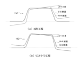
- FIG. 1 is an explanatory diagram of the die projection angle in the molding process and the restriking process in an example of the invention.
- FIG. 2 is an explanatory diagram of the stress state at the bottom dead center of the forming process and the restriking process in an example of the invention.
- FIG. 3 is an explanatory diagram of an example of a press-formed product to which the present invention is directed.
- FIG. 4 is an explanatory diagram of the forming step and the restriking step according to the embodiment.
- FIG. 5 is an explanatory diagram of the twist angle of a press-formed product.
- FIG. 6 is an explanatory diagram of the die projection angle.
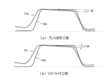
- FIG. 7 is an explanatory diagram of the twist angle in a press-formed product after a forming process and a press-formed product after a restriking process in a conventional example.
- FIG. 8 is an explanatory diagram of the stress state at the bottom dead center in the forming process and the restriking process in the conventional example.
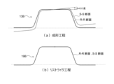
- FIG. 9 is an explanatory diagram of the die projection angle in the molding process and the restriking process in the comparative example.
- FIG. 10 is an explanatory diagram of the stress state at the forming bottom dead center in the forming process and the restriking process in the comparative example.
- FIG. 11 is an explanatory diagram of a press-formed product that is the subject of the examples (part 1).
- FIG. 12 is an explanatory diagram of the press-formed product that was the subject of the embodiment (part 2).
- the press-formed product 1 that is the subject of the present invention is curved when viewed from above, as shown as an example in Figure 3, and has a hat-shaped cross-section having at least a top plate portion 3, a vertical wall portion 5 continuing from the top plate portion 3, and a flange portion 7 at the lower end of the vertical wall portion 5.
- the flange portion 7 is included, but the presence of the flange portion 7 is not essential.
- the operation of the present invention will be explained using as an example the press-formed product 1 shown in Figure 3, which is formed using a 1470 MPa-class steel plate with a plate thickness of 1.0 mm as the blank 9.
- the press-formed product 1 as shown in Figure 3 is formed in a forming process ( Figure 4(a)) and a restriking process (Figure 4(b)) as shown in Figure 4.
- a blank 9 which is a metal plate
- a forming die 15 is moved relatively to form a formed product 17 having a top plate portion 3, a vertical wall portion 5, and a flange portion 7.
- the formed product 17 formed in the forming process is formed by a restriking punch 19 and a restriking die 21.
- Figure 5(a) is a plan view of the press-formed product 1.
- Figure 5(b) is a diagram showing the P-P cross section of the longitudinal center of the press-formed product 1 together with the forming surface of the longitudinal center of the restriking punch 19.
- Figure 5(c) is a diagram showing the Q-Q cross section near the longitudinal end of the press-formed product 1 together with the forming surface of the longitudinal center of the restriking punch 19.
- the twist angle of the molded product 17 and the press-molded product 1 is defined as the angle between the cross section of the top plate forming surface at the longitudinal center of the forming punch 13 and the restriking punch 19 and the cross section of the top plate forming surface at the longitudinal center of the forming punch 13 and the restriking punch 19, based on the cross section (see FIG. 5(b)).
- the cross section of the top plate 3 at the longitudinal end is defined as the angle between the cross section of the top plate forming surface at the longitudinal center of the forming punch 13 and the restriking punch 19.
- the angle is defined as a + (plus) value when it is shifted leftward (counterclockwise) on the page, with the outer side of the curve being the left and the inner side of the curve being the right, and a - (minus) value when it is shifted rightward (clockwise) on the page.
- the die projection angle is defined as the angle of the cross section (S-S cross section) of the longitudinal end (for example, about 10 mm inside from the extreme end) (see Figs. 6(a) and (c)) based on the cross section (R-R cross section) (see Figs. 6(a) and (b)) of the longitudinal center of the top plate forming surface of the forming punch 13 and the restriking punch 19.
- the die projection angle is defined as a + (plus) value when it rotates left (counterclockwise) on the page, with the outside of the curve on the left and the inside of the curve on the right, and a - (minus) value when it rotates right (clockwise) on the page.
- FIG. 7 shows the Q-Q cross section (see FIG. 5) near the longitudinal end of the molded product 17A after the molding process (FIG. 7(a)) and the press-molded product 1A after the restrike process (FIG. 7(b)) of the conventional example.
- the twist angle due to springback after the molding process remains negative, and is not corrected even in the restrike process and remains almost as it is.
- the twist angle due to springback of the molded product 17A after the press molding process shown in FIG. 7(a) is -3.1 degrees.
- the twist angle due to springback of the press-molded product 1A after restrike shown in FIG. 7(b) is -3.4 degrees.
- FIG. 8 is a contour diagram of the analysis results.
- Figure 8(a) is a diagram showing the stress distribution at the bottom dead center of the formed product 17A after the forming process.
- Figure 8(b) is a diagram showing the stress distribution at the bottom dead center of the press-formed product 1A after the restriking process.
- large compressive stress due to shrink flange deformation occurs in the outer flange parts 177A and 7A, and large tensile stress due to stretch flange deformation occurs in the inner flange parts 177A and 7A.
- the one-step projection angle is an angle applied to the longitudinal end of the forming die so that the twist due to springback when the press-formed product is press-formed in one process is equal to or less than a predetermined threshold value.
- the predetermined threshold value is the upper limit of the twist angle that is allowable for a press-formed product.
- the one-step projection angle in this example is 6.0 degrees in the opposite direction to the twist due to springback with respect to the die of the target shape.
- a one-step angle is provided in anticipation of springback during the forming process, so there is almost no twisting due to springback after the forming process, and when the part is formed using the restriking die 19B of the target shape in the restriking process, the part is shaped close to the target shape.
- FIG. 10 is a contour diagram of the analysis results.
- Figure 10(a) is a diagram showing the stress distribution at the bottom dead point of the formed product 17B after the forming process.
- Figure 10(b) is a diagram showing the stress distribution at the bottom dead point of the press-formed product 1B after the restriking process.
- the forming step and the restriking step are carried out as follows.
- press forming is performed using a forming die 13C (see FIG. 1(a)) to which a first projection angle is imparted such that a twist (reverse twist) caused by springback in the opposite direction to the twist (positive twist) caused by springback when press forming is performed in one step without imparting a projection angle to the die remains.
- the twist after springback is most reduced by setting the one-step projection angle to 6.0 degrees, so in order to leave the reverse twist, the first projection angle is made larger than 6.0 degrees.
- the first projection angle of the S-S cross section in the longitudinal direction of the die is set to 8.0 degrees with respect to the R-R cross section at the center of the longitudinal direction of the die in FIG. 6.
- the molded product 17C molded in the molding process is press molded using a restriking die 19C to which a second prospect angle that reduces the reverse twist is imparted.
- the reverse twist remains due to springback, so in order to reduce this, as shown in FIG. 1(b), the mold is molded using a restriking die 19C to which a second prospect angle in the same direction as the springback is imparted (in this example, the angle of the S-S cross section near the end of the die in the longitudinal direction is -6.0 degrees with respect to the R-R cross section at the center of the die in the longitudinal direction of FIG. 6) to reduce the reverse twist, to obtain a target shape.
- the absolute value of the second prospect angle in the restriking process is preferably smaller than the absolute value of the first prospect angle.
- Figure 2 shows the stress distribution at the bottom dead center of the forming process, which was determined by FEM analysis of these forming and restriking processes.
- Figure 2(a) in the forming process, in the longitudinal center of the formed product 17C, large compressive stress occurs in the outer flange portion 177C due to shrink flange deformation, and large tensile stress occurs in the inner flange portion 177C due to stretch flange deformation.
- large tensile stress occurs on the outer side of the curve of the top plate portion 173C
- large compressive stress occurs on the inner side of the curve of the top plate portion 173C.
- FIG. 2(b) of the present invention Comparing FIG. 2(b) of the present invention with FIG. 10(b) of the comparative example, in the case of the present invention shown in FIG. 2(b), the compressive stress of the outer flange portion 7C and the tensile stress of the inner flange portion 7C are reduced more than in the comparative example. Furthermore, in the case of the present invention shown in FIG. 2(b), the tensile stress on the outer side of the curve of the top plate portion 3C and the compressive stress on the inner side of the curve of the top plate portion 3C are also reduced more than in the comparative example. That is, the stress distribution of the press-formed product 1C after the restriking process of FIG.
- the present invention is not limited to this.
- the present invention can also be applied to U-shaped cross-section parts that are curved when viewed from above and consist of a top plate and vertical wall portions on both sides, Z-shaped cross-section parts that consist of a vertical wall portion and a flange portion on only one side of the top plate, and L-shaped cross-section parts that consist of a top plate and a vertical wall portion on only one side. It can also be applied in cases where part of the press-molded product is curved.
- the shape of the press-formed product 1 is a hat-shaped cross-sectional shape having a top plate portion 3, a vertical wall portion 5 continuing with the top plate portion 3, and a flange portion 7 continuing with the vertical wall portion 5, and the cross-sectional dimensions are as shown in FIG. 12.
- the twist angle due to springback and the die projection angle are based on the cross section of the top plate forming portion at the center of the die longitudinal direction, with the outside of the curve being the left and the inside of the curve being the right, and the leftward rotation on the paper is a + (plus) value, and the rightward rotation on the paper is a - (minus) value.
- the direction of twist (positive twist) due to springback was determined by molding using a die with no die projection angle. Furthermore, the one-step projection angle that can minimize twist due to springback in one step was determined to be 6.0 degrees. After that, the molding process and restriking process were carried out for each of the conventional example, comparative example, and invention example described above. The results are shown in Table 1.
- Comparative examples No. 2-1 (1470 MPa class material) and No. 2-2 (980 MPa class material) have a one-step projection angle of 6.0 degrees in the forming process and a die projection angle of 0 degrees in the restriking process.
- the torsion angle of the press-formed product 1A after restriking was reduced to 0.6 degrees in the case of No. 2-1 (1470 MPa class material), but was 2.0 degrees in the case of No. 2-2 (980 MPa class material), resulting in significant torsion due to springback.
- the difference in torsion angle due to material strength after the restriking process was -1.4 degrees, which was greater than the difference between the conventional examples No. 1-1 and No. 1-2.
- the first projection angle in the forming process was 7.0 degrees
- the second projection angle in the restriking process was -2.0 degrees
- the torsion angle of the press-formed product 1C after restriking was 0.3 degrees in the case of No. 3-1 (1470 MPa class material) and 0.6 degrees in the case of No. 3-2 (980 MPa class material), and the torsion due to springback was reduced.
- the difference in the torsion angle due to the material strength after the restriking process was -0.3 degrees, and even though the material strength is significantly different between the 1470 MPa class material and the 980 MPa class material, the difference in the torsion angle due to the difference in material strength using the same die was small. Therefore, it was found that springback can be sufficiently reduced even when press forming is performed using different materials using the same die.
- the first projection angle in the forming process was increased to 8.0 degrees, and the die projection angle in the restriking process was 0 degrees.
- the twist angle of the press-formed product 1B after these restriking processes was 2.2 degrees for No. 4-1 (1470 MPa class material) and 3.4 degrees for No. 4-2 (980 MPa class material).
- the difference in twist angle due to material strength after the restriking process was large at -1.2 degrees.
- Inventive examples No. 5-1 (1470 MPa class material) and No. 5-2 (980 MPa class material) have a first projection angle of 8.0 degrees in the forming process and a second projection angle of -6.0 degrees in the restriking process.
- the twist angle of the press-formed product 1C after restriking was 0.1 degrees for No. 5-1 (1470 MPa class material) and 0.2 degrees for No. 5-2 (980 MPa class material), and both 1470 MPa class material and 980 MPa class material were able to sufficiently reduce twist due to springback.
- the difference in twist angle due to material strength after the restriking process was -0.1 degrees, and even though the material strength of the 1470 MPa class material and the 980 MPa class material was significantly different, the difference in twist angle due to the difference in material strength was small even when the same die was used. Therefore, it has been found that the present invention can sufficiently reduce springback even when press molding different materials using the same die.
- the present invention can provide a method for manufacturing a press-molded product that can reduce shape errors caused by springback after demolding in a press-molded product that is curved when viewed from above and has at least a top plate portion and a vertical wall portion continuing from the top plate portion.
Landscapes
- Engineering & Computer Science (AREA)
- Mechanical Engineering (AREA)
- Shaping Metal By Deep-Drawing, Or The Like (AREA)
Abstract
Description
(1)本発明に係るプレス成形品の製造方法は、上面視で湾曲し、少なくとも、天板部と、天板部から連続する縦壁部とを有し、離型後のスプリングバックによる目標形状との誤差を低減するために、金型に見込み角を付与して製造されるプレス成形品の製造方法であって、金型に見込み角を付与せずに1工程でプレス成形した際にスプリングバックにより生ずる捩れ(正捩れ)と逆方向のスプリングバックによる捩れ(逆捩れ)が残存するような第1見込み角を付与した成形金型を用いてプレス成形する成形工程と、該成形工程で成形された成形品を第2見込み角を付与したリストライク金型を用いてプレス成形するリストライク工程と、を備えたことを特徴とするものである。
<従来例>
従来例は、成形工程を行った後、同じ形状の金型でリストライクしていた。図7は、従来例の成形工程後(図7(a))の成形品17A及びリストライク工程後(図7(b))のプレス成形品1Aにおける長手方向端部近傍のQ-Q断面(図5参照)を示している。従来例では、図7に示す通り、成形工程後のスプリングバックによる捩れ角はマイナスのままであり、リストライク工程でも矯正されずにほぼそのまま残留する。図7(a)に示すプレス成形工程後の成形品17Aのスプリングバックによる捩れ角は、-3.1度である。図7(b)に示すリストライク後のプレス成形品1Aのスプリングバックによる捩れ角は、-3.4度である。
比較例は、従来例で発生した捩れを解消するために、成形工程において長手方向中央部から長手方向端部に向かって、長手方向端部近傍(最端部から10mm内部)にて、1工程見込み角を付与した成形金型(成形用パンチ13B)を用いて成形し(図9(a)参照)、その後にリストライク工程で目標形状のリストライク金型(リストライク用パンチ19B)で成形する(図9(b)参照)。ここで、1工程見込み角とは、プレス成形品を1工程でプレス成形した際のスプリングバックによる捩れが、所定の閾値以下となるように、成形金型の長手方向端部に付与する角度である。また、所定の閾値とは、プレス成形品として許容できる捩れ角度の上限値のことである。本例の1工程見込み角は、目標形状の金型に対してスプリングバックの捩れと逆方向に6.0度である。
<成形工程>
成形工程は、金型に見込み角を付与せずに1工程でプレス成形した際のスプリングバックにより生ずる捩れ(正捩れ)とは逆方向のスプリングバックによる捩れ(逆捩れ)が残存するような第1見込み角を付与した成形金型13C(図1(a)参照)を用いてプレス成形する。比較例で示したように、本例では、1工程見込み角を6.0度にすることで、スプリングバック後の捩れが最も低減されるので、逆捩れを残存させるには、第1見込み角を6.0度よりも大きくする。具体的には、図1(a)の成形工程では、図6の金型長手方向中央部のR-R断面に対し、金型長手方向のS-S断面の第1見込み角を8.0度とする。
リストライク工程は、成形工程で成形された成形品17Cを、前記逆捩れを低減する第2見込み角を付与したリストライク金型19Cを用いてプレス成形する。成形工程の離型後には、スプリングバックによって逆捩れが残存しているので、これを低減するために図1(b)に示すように、逆捩れを低減するためにスプリングバックと同方向の第2見込み角(本例では図6の金型長手方向中央部のR-R断面に対し、金型長手方向端部近傍のS-S断面の角度が-6.0度)を付与したリストライク金型19Cで成形して、目標形状とする。なお、リストライク工程における第2見込み角の絶対値は、第1見込み角の絶対値よりも小さくすることが好ましい。

3 天板部
5 縦壁部
7 フランジ部
9 ブランク
11 パッド
13 成形用パンチ
15 成形用ダイ
17 成形品
19 リストライク用パンチ
21 リストライク用ダイ
1A プレス成形品(従来例)
3A 天板部
7A フランジ部
1B プレス成形品(比較例)
3B 天板部
7B フランジ部
1C プレス成形品(発明例)
3C 天板部
7C フランジ部
13A 成形用パンチ(従来例)
13B 成形用パンチ(比較例)
13C 成形用パンチ(発明例)
17A 成形品(従来例)
173A 天板部
177A フランジ部
17B 成形品(比較例)
173B 天板部
177B フランジ部
17C 成形品(発明例)
173C 天板部
177C フランジ部
19A リストライク用パンチ(従来例)
19B リストライク用パンチ(比較例)
19C リストライク用パンチ(発明例)
Claims (7)
- 上面視で湾曲し、少なくとも、天板部と、天板部から連続する縦壁部とを有するプレス成形品の製造方法であって、
金型に見込み角を付与せずに1工程でプレス成形した際にスプリングバックにより生ずる捩れ(正捩れ)と逆方向のスプリングバックによる捩れ(逆捩れ)が残存するような第1見込み角を付与した成形金型を用いてプレス成形する成形工程と、
該成形工程で成形された成形品を第2見込み角を付与したリストライク金型を用いてプレス成形するリストライク工程と、を備えたことを特徴とするプレス成形品の製造方法。 - 前記第1見込み角は、前記プレス成形品を1工程でプレス成形した際のスプリングバックによる捩れが所定の閾値以下となる1工程見込み角よりも大きいことを特徴とする請求項1に記載のプレス成形品の製造方法。
- 予め、前記プレス成形品のプレス成形解析およびスプリングバック解析を行って、スプリングバックによる捩れの方向と前記1工程見込み角を求めることを特徴とする請求項2に記載のプレス成形品の製造方法。
- 予め、前記プレス成形品の実プレス成形を行って、スプリングバックによる捩れの方向と前記1工程見込み角を求めることを特徴とする請求項2に記載のプレス成形品の製造方法。
- 前記第1見込み角又は前記第2見込み角は、前記成形金型又は前記リストライク金型の長手方向中央の幅方向断面の天板成形面部を基準として、前記成形金型又は前記リストライク金型の長手方向端部における幅方向断面の天板成形面部の傾斜角とすることを特徴とする請求項1乃至4のいずれか一項に記載のプレス成形品の製造方法。
- リストライク工程における第2見込み角の絶対値を、第1見込み角の絶対値より小さくしたことを特徴とする請求項1乃至4のいずれか一項に記載のプレス成形品の製造方法。
- リストライク工程における第2見込み角の絶対値を、第1見込み角の絶対値より小さくしたことを特徴とする請求項5に記載のプレス成形品の製造方法。
Priority Applications (5)
| Application Number | Priority Date | Filing Date | Title |
|---|---|---|---|
| US19/109,245 US20260077399A1 (en) | 2022-09-28 | 2023-06-06 | Method of manufacturing press-formed part |
| EP23871306.9A EP4570397A4 (en) | 2022-09-28 | 2023-06-06 | METHOD FOR MANUFACTURING A PRESS-FORMED PRODUCT |
| KR1020257009037A KR20250055551A (ko) | 2022-09-28 | 2023-06-06 | 프레스 성형품의 제조 방법 |
| CN202380068707.3A CN119947843A (zh) | 2022-09-28 | 2023-06-06 | 压制成型品的制造方法 |
| MX2025003701A MX2025003701A (es) | 2022-09-28 | 2025-03-27 | Metodo de fabricacion de parte conformada en prensa |
Applications Claiming Priority (2)
| Application Number | Priority Date | Filing Date | Title |
|---|---|---|---|
| JP2022-154725 | 2022-09-28 | ||
| JP2022154725A JP7476935B2 (ja) | 2022-09-28 | 2022-09-28 | プレス成形品の製造方法 |
Publications (1)
| Publication Number | Publication Date |
|---|---|
| WO2024070061A1 true WO2024070061A1 (ja) | 2024-04-04 |
Family
ID=90476773
Family Applications (1)
| Application Number | Title | Priority Date | Filing Date |
|---|---|---|---|
| PCT/JP2023/020982 Ceased WO2024070061A1 (ja) | 2022-09-28 | 2023-06-06 | プレス成形品の製造方法 |
Country Status (7)
| Country | Link |
|---|---|
| US (1) | US20260077399A1 (ja) |
| EP (1) | EP4570397A4 (ja) |
| JP (1) | JP7476935B2 (ja) |
| KR (1) | KR20250055551A (ja) |
| CN (1) | CN119947843A (ja) |
| MX (1) | MX2025003701A (ja) |
| WO (1) | WO2024070061A1 (ja) |
Citations (5)
| Publication number | Priority date | Publication date | Assignee | Title |
|---|---|---|---|---|
| JP2007130671A (ja) | 2005-11-11 | 2007-05-31 | M & M Research:Kk | プレス加工におけるねじれ判定とその修正プログラム、およびその方法 |
| JP2007253173A (ja) | 2006-03-22 | 2007-10-04 | Press Kogyo Co Ltd | チャンネル材の加工方法およびチャンネル材 |
| JP2016150354A (ja) * | 2015-02-17 | 2016-08-22 | Jfeスチール株式会社 | プレス成形方法、プレス成形金型 |
| WO2020235152A1 (ja) * | 2019-05-20 | 2020-11-26 | Jfeスチール株式会社 | プレス部品の製造方法、及び形状矯正用金型 |
| JP2022087659A (ja) * | 2020-12-01 | 2022-06-13 | 株式会社神戸製鋼所 | 鋼部品の製造方法 |
Family Cites Families (2)
| Publication number | Priority date | Publication date | Assignee | Title |
|---|---|---|---|---|
| JP5861749B1 (ja) * | 2014-07-30 | 2016-02-16 | Jfeスチール株式会社 | プレス成形方法 |
| JP6380294B2 (ja) * | 2015-08-24 | 2018-08-29 | Jfeスチール株式会社 | プレス成形方法 |
-
2022
- 2022-09-28 JP JP2022154725A patent/JP7476935B2/ja active Active
-
2023
- 2023-06-06 US US19/109,245 patent/US20260077399A1/en active Pending
- 2023-06-06 CN CN202380068707.3A patent/CN119947843A/zh active Pending
- 2023-06-06 EP EP23871306.9A patent/EP4570397A4/en active Pending
- 2023-06-06 KR KR1020257009037A patent/KR20250055551A/ko active Pending
- 2023-06-06 WO PCT/JP2023/020982 patent/WO2024070061A1/ja not_active Ceased
-
2025
- 2025-03-27 MX MX2025003701A patent/MX2025003701A/es unknown
Patent Citations (5)
| Publication number | Priority date | Publication date | Assignee | Title |
|---|---|---|---|---|
| JP2007130671A (ja) | 2005-11-11 | 2007-05-31 | M & M Research:Kk | プレス加工におけるねじれ判定とその修正プログラム、およびその方法 |
| JP2007253173A (ja) | 2006-03-22 | 2007-10-04 | Press Kogyo Co Ltd | チャンネル材の加工方法およびチャンネル材 |
| JP2016150354A (ja) * | 2015-02-17 | 2016-08-22 | Jfeスチール株式会社 | プレス成形方法、プレス成形金型 |
| WO2020235152A1 (ja) * | 2019-05-20 | 2020-11-26 | Jfeスチール株式会社 | プレス部品の製造方法、及び形状矯正用金型 |
| JP2022087659A (ja) * | 2020-12-01 | 2022-06-13 | 株式会社神戸製鋼所 | 鋼部品の製造方法 |
Non-Patent Citations (1)
| Title |
|---|
| See also references of EP4570397A4 |
Also Published As
| Publication number | Publication date |
|---|---|
| JP2024048676A (ja) | 2024-04-09 |
| US20260077399A1 (en) | 2026-03-19 |
| EP4570397A4 (en) | 2025-12-24 |
| KR20250055551A (ko) | 2025-04-24 |
| CN119947843A (zh) | 2025-05-06 |
| EP4570397A1 (en) | 2025-06-18 |
| JP7476935B2 (ja) | 2024-05-01 |
| MX2025003701A (es) | 2025-05-02 |
Similar Documents
| Publication | Publication Date | Title |
|---|---|---|
| TWI448338B (zh) | 具有l字狀形狀之零件的壓製成形方法 | |
| CA2885406C (en) | Method for producing center pillar reinforcement | |
| JP5380890B2 (ja) | 形状凍結性に優れたプレス成形方法およびその装置 | |
| JP6631759B1 (ja) | プレス部品の製造方法、プレス成形装置及びプレス成形用の金属板 | |
| JP2009241109A (ja) | チャンネル部材の曲げ成形方法 | |
| CN105813773A (zh) | 钢板原材料、其制造方法及制造装置以及使用了该钢板原材料的压制成型品的制造方法 | |
| KR101867744B1 (ko) | 프레스 성형 방법 및 프레스 제품의 제조 방법 그리고 프레스 성형 장치 | |
| WO2021240941A1 (ja) | プレス成形方法 | |
| US10988004B2 (en) | Press forming apparatus and outer panel | |
| JP2006272413A (ja) | 湾曲状チャンネル部材の成形方法 | |
| WO2024053186A1 (ja) | プレス成形品の製造方法 | |
| CN111801175B (zh) | 冲压成型品的设计方法、冲压成型模具、冲压成型品以及冲压成型品的制造方法 | |
| JP2017042773A (ja) | プレス成形方法 | |
| JP7476935B2 (ja) | プレス成形品の製造方法 | |
| WO2022239340A1 (ja) | プレス成形方法 | |
| JP7494883B2 (ja) | プレス成形方法およびプレス成形品の製造方法 | |
| JP5609630B2 (ja) | 板金の歪み矯正装置 | |
| KR102360563B1 (ko) | 빔류의 성형방법 | |
| JP6179527B2 (ja) | プレス成形方法 | |
| JP7593385B2 (ja) | プレス成形方法及びプレス成形品の製造方法 | |
| JP7800337B2 (ja) | 非対称フランジ部を有するプレス成形品の製造方法 | |
| JP7831456B2 (ja) | プレス成形品の製造方法 | |
| JP7472939B2 (ja) | プレス成形品の製造方法、プレス成形金型 | |
| JP2025186833A (ja) | プレス成形品の製造方法およびプレス成形装置 | |
| WO2024047968A1 (ja) | プレス成形品の製造方法 |
Legal Events
| Date | Code | Title | Description |
|---|---|---|---|
| 121 | Ep: the epo has been informed by wipo that ep was designated in this application |
Ref document number: 23871306 Country of ref document: EP Kind code of ref document: A1 |
|
| WWE | Wipo information: entry into national phase |
Ref document number: 202517021768 Country of ref document: IN |
|
| WWE | Wipo information: entry into national phase |
Ref document number: 2023871306 Country of ref document: EP |
|
| ENP | Entry into the national phase |
Ref document number: 20257009037 Country of ref document: KR Kind code of ref document: A |
|
| WWE | Wipo information: entry into national phase |
Ref document number: 1020257009037 Country of ref document: KR |
|
| ENP | Entry into the national phase |
Ref document number: 2023871306 Country of ref document: EP Effective date: 20250313 |
|
| WWE | Wipo information: entry into national phase |
Ref document number: 202380068707.3 Country of ref document: CN |
|
| WWE | Wipo information: entry into national phase |
Ref document number: 2501002035 Country of ref document: TH Ref document number: MX/A/2025/003701 Country of ref document: MX |
|
| WWP | Wipo information: published in national office |
Ref document number: 1020257009037 Country of ref document: KR |
|
| WWP | Wipo information: published in national office |
Ref document number: 202517021768 Country of ref document: IN |
|
| NENP | Non-entry into the national phase |
Ref country code: DE |
|
| WWP | Wipo information: published in national office |
Ref document number: MX/A/2025/003701 Country of ref document: MX |
|
| WWP | Wipo information: published in national office |
Ref document number: 202380068707.3 Country of ref document: CN |
|
| WWP | Wipo information: published in national office |
Ref document number: 2023871306 Country of ref document: EP |